Finger-Like Carbon-Based Nanostructures Produced by Combustion of Flour-Based Sticks (Spaghetti)

1
Combustion Physics, Lund University, P.O. BOX 118, SE 221 00 Lund, Sweden
2
Centre for Analysis and Synthesis, Department of Chemistry, Lund University, P.O. BOX 124, SE 221 00 Lund, Sweden
*
Author to whom correspondence should be addressed.
C 2019, 5(2), 21; https://0-doi-org.brum.beds.ac.uk/10.3390/c5020021
Submission received: 1 March 2019
/
Revised: 29 March 2019
/
Accepted: 16 April 2019
/
Published: 29 April 2019
(This article belongs to the Special Issue Advanced Coal, Biomass and Waste Conversion Technologies)
Abstract
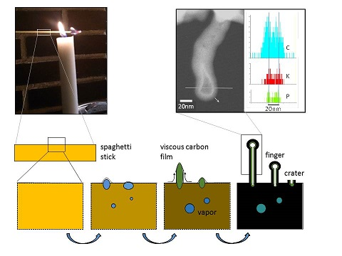
:Biomass is becoming particularly important as a starting material for advanced carbon structures. In this study, we found interesting nanostructures on the surface of burnt spaghetti using scanning electron microscopy, transmission electron microscopy (TEM), and energy dispersive X-ray spectroscopy (EDX) for analysis. The structures were elongated and finger-like, with evidence that the tubes have shell and core components. The shell was carbon that included amorphous and layered graphene structures. EDX showed enriched potassium and phosphorous in the core and at the tip of the tubes. The results indicate that tube formation depends on phase separation of polar/ionic and nonpolar moieties when water is produced in the biomass from the pyrolysis/combustion. The tube growth is most probably due to the raising pressure of vapor that cannot escape through the carbon film that is formed at the surface of the stick from flame heat. This process resembles glass blowing or volcanic activity, where the carbon acts as the glass or earth’s crust, respectively. These observations suggest that new interesting tubular nanostructures with different properties on the inside and outside can be produced in a relatively simple way, utilizing processes of combustion of starch-rich biomass materials.

1. Introduction
Combustion-like processes are an important means of producing carbon structures. When the main chemistry occurs in the gas phase this can lead to the formation of a soot with a variety of structures including fullerenes, nanotubes, graphene, and graphite [1,2,3,4,5]. Biomass is becoming particularly important as a source for advanced carbon structures. A recent review of the progress of biomass-derived carbon materials for use in e.g., fuel cells, water-splitting devices, super-capacitors, and batteries has been presented [6]. The processes for synthesizing the carbon materials include direct pyrolysis, hydrothermal carbonization (HTC), and iono-thermal carbonization. The structures that have been produced in these processes include: sponge-like nanostructures derived from HTC of biomass [7,8], tubular/worm-like carbon nanotube (CNT) structures obtained by microwave induced processing [9], and multiwall CNTs by vapor deposition of ethanol on bamboo charcoal [10].
Starting from an intuitive idea that occurred when observing how spaghetti became carbonized when spilled on a hot cooking plate during food preparation, we decided to investigate the surface of carbonized spaghetti sticks.
The main instrumentation for these initial investigations was electron microscopy, since it allows for the characterization of nanometer-sized carbon with a high structural resolution [11]. Electron microscopy will be important for the continuation of our studies, and it may allow us to study the carbonizing of the spaghetti surface in situ, as has been done in related studies, e.g., on the synthesis and functional mechanisms in nanoscale materials [12], and in catalysis [13].
In this work, we focused on investigating the surface structures of our samples, utilizing scanning electron microscopy (SEM), transmission electron microscopy (TEM), and scanning transmission electron microscopy (STEM). The composition of the material was investigated by energy dispersive X-ray spectroscopy (EDX). Applying these techniques, we found networks and patches of finger-like carbon-based and chemically heterogeneous nanostructures that could vary in properties, depending on the combustion conditions and preparation of the sticks. In this work, we report and discuss the first results from our investigations that we feel can contribute to a new route of studies and potentially the development and production of new materials of functionalized carbon based nanostructures from biomass.
At a late stage in the preparation of this manuscript, a closely related study by Gao et al (2018) [14] came to our attention. In their work, CNTs were found to have formed on both the inner and outer surfaces of porous activated wheat dough via a simple one-step heat treatment. Electron microscopy was also used extensively in their characterization, alongside many other techniques. Their proposed growth mechanism differs in many respects from the one proposed for our material, but the particular application they explored—namely electrodes for energy storage—is one that we also had envisaged.
2. Materials and Methods
Regular dried durum wheat spaghetti (Barilla Spaghetti No. 5) was obtained from a grocery store. The main material examined in this study, called Sample 1, was carbonized by burning in a candle flame. A further spaghetti stick was additionally treated by cooking in salt water (NaCl, 3% by weight) for 15 min, and then dried in air before it was burned, and it is referred to as Sample 2.
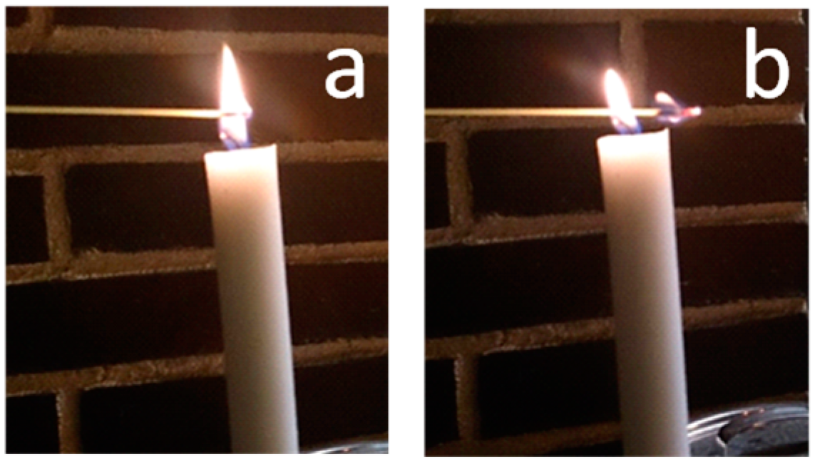
The design of the experimental set-up for combustion was straightforward, yet despite this simplicity, the end material provided a rich structure to investigate, and the results were reproducible. The stick of spaghetti for Sample 1 was inserted in a candle flame to start the combustion. This part of the stick therefore burned at a relatively high temperature and we denote the area as Sample 1a (see Figure 1a). On removal from the flame, the combustion continued (Figure 1b) at a lower temperature and we call this region Sample 1b. We estimated the temperatures of the flames for the two conditions using a thin thermocouple (Type R) and obtained peak temperatures of 1230 ± 30 and 1160 ± 30 °C, respectively. These values should be regarded as approximate values, considering the small volumes that the flames occupied and that radiative losses from the thermocouple were not taken into account. Sample 2 burning was conducted the same way. The samples were then investigated by SEM in a JSM-6700F operating at 5 and 10kV, and by TEM in a JEM-3000F operating at 300kV. Both instruments were manufactured by JEOL Ltd, Tokyo, Japan. EDX was performed with X-MaxN Silicon Drift Detectors manufactured by Oxford Instruments plc, High Wycombe, UK with data analyzed by INCA software (TEM) and AZtec software (SEM).
3. Results
SEM investigation of the carbonized surface of Sample 1a revealed patches having dimensions in the 10–20 µm range which at higher magnification were found to be “forests” of nanostructures or finger-like protrusions, as shown in Figure 2. The nanostructures were up to 500 nm in length. with diameters in the 50–80 nm range.
For more detailed observations, TEM was used and for this technique it was necessary first to remove surface material from the carbonized stick and support it on a standard holey carbon film/copper 3 mm grid. The removal was achieved simply by scraping surface material off with a scalpel and allowing the fragments to adhere to the carbon film.
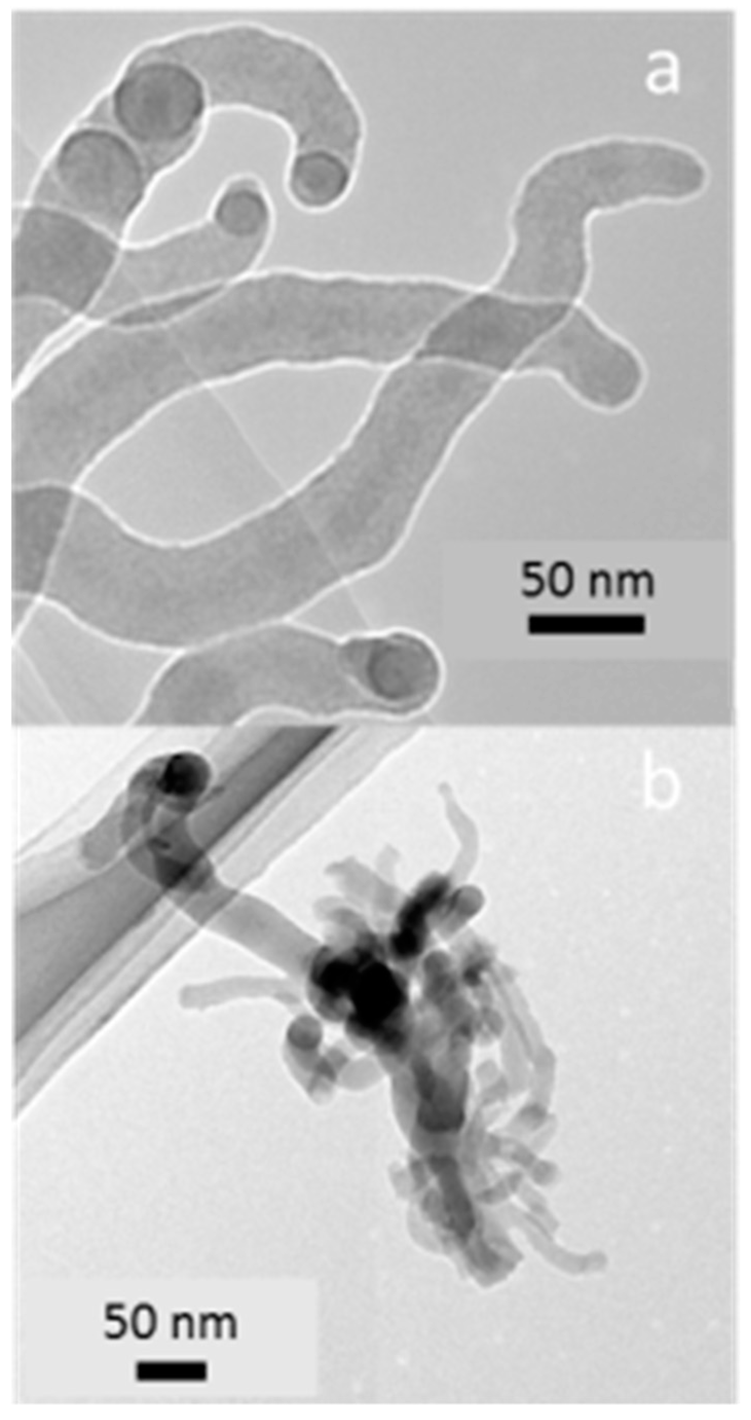
For Sample 1a, we found a variety of fragment types, shown in Figure 3. Finger-like protrusions were found that had broken away from the surface material (Figure 3a,b) and their dimensions were in line with the SEM observation. Some clustering of the fingers may have occurred during the preparation of the TEM sample. The fingers have a contorted shape, with a darker central string, typically narrower than 20 nm, which appears in some cases to bulge out at the tip of the finger. Some darker regions may be caused by fingers aligning parallel to the direction of the electron beam, or fingers overlapping each other. The darker contrast in the TEM image of the central string could be explained by higher local concentrations of atomic species that are heavier than carbon, e.g., alkali metals and phosphorous, which are known to be contained in biomass. The tip of a finger was usually slightly bulged (see Figure 2d), and of different contrast on the inside (see Figure 3a and Figure 4).
Some fragments (e.g., Figure 4a) had protrusions still attached to surface material, as we observed in the SEM (Figure 2c). Other fragments (Figure 4b) appeared to be surface material where the finger-like protrusions had broken off leaving behind circular features—“pits” or “craters”—having diameters corresponding to the diameter of the fingers. A higher intensity (stronger signal) in the STEM dark field image arises from either a greater thickness or a higher concentration of high Z (atomic number) elements. In order to investigate how the atomic elements were distributed over different regions of fingers and pits/craters, EDX spectra or maps were generated on both fingers and pits.
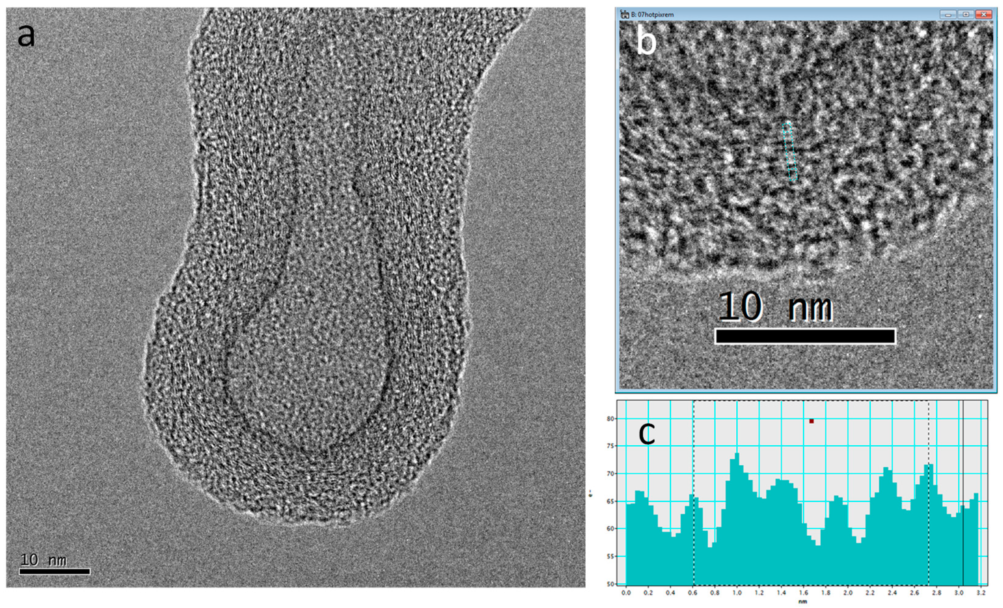
Figure 5 shows a high resolution transmission electron microscopy (HRTEM) image of the tip of one finger. A clear boundary is apparent, separating the shell from the core. The image of the core region, or inner part of the tip, includes the top and bottom shell layers. We believe however, that the sharp internal boundary indicates a different density in the core compared to the shell and that it may even be hollow. The enlarged area from the shell region has partial layering in the shell. The layering shown with 0.42 nm spacing in Figure 5b varies around 0.35 nm, which is that expected for graphitic layers of carbon.
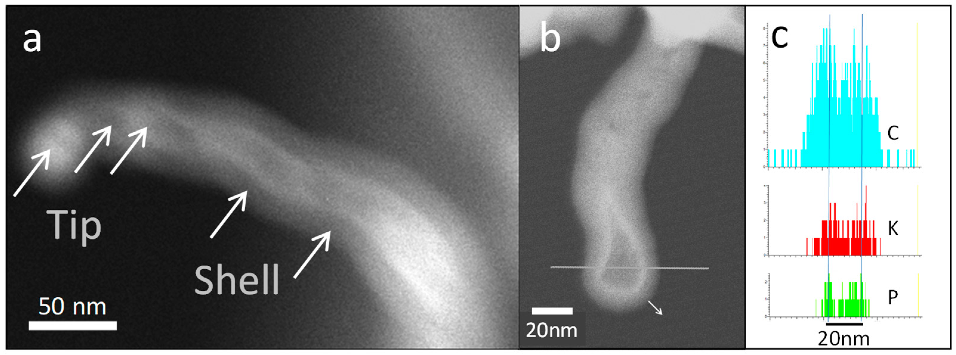
In Figure 6a, another finger is shown, imaged using STEM dark field. Brighter regions, principally along the finger spine, are due to greater electron scattering and probably indicate the presence of elements with a higher atomic number than carbon. Images such as Figure 6a were often found to be blurred because of movement—uniform drift or vibrations—of the fingers. Such movement makes elemental mapping of the entire region difficult, as it requires long exposure times. EDX point measurements were attempted, and we report in Table 1 on three points from the tip and spine of the finger and on two from the shell, i.e., the outer parts of the finger. The acquisition time for each spectra was short (30 s) making the data rather noisy, but even so, clear trends in composition can be seen.
The tip/spine regions showed a marked concentration of K, P, and O, relative to the shell. The atomic numbers of K and P (19 and 15) are much higher than C (6), so this finding is consistent with the contrast seen in Figure 6a. The composition ratios between the oxygen, phosphorous, and potassium suggest that KH2PO4 may be an important component in the tip and spine region. Numbers for Na, S and Cl are included in the table for completeness, but the amounts present in this sample are negligible. H is not detectable by EDX, but is assumed to be present in the form of hydrocarbons, or remnant water, or hydrated phosphates. The shell may be a combination of graphitic-like carbon (as evidenced in Figure 5a) and hydrocarbons as suggested by the presence of O, and N (Table 1).
In an effort to further investigate the separation of phases between C on one hand and P and K on the other, we attempted an EDX line scan across the finger structure of Figure 5a. The line scanned is indicated in Figure 6b, and the signals for C, K and P are shown in Figure 6c. There was a movement of the finger during the 2 min EDX line scan of about 5 nm, indicated by the small arrow in Figure 6b. Nevertheless, from the elemental profiles seen in Figure 6c, we see that C is concentrated into two broad peaks, as expected for an outer shell, while K and P are found in two peaks having a smaller separation compared to the C peaks. The combination of this finding with the observation of sharp white contrast in Figure 6b means that K and P have probably formed as part of a thin inner shell, lining the inside of the carbon-rich outer shell.
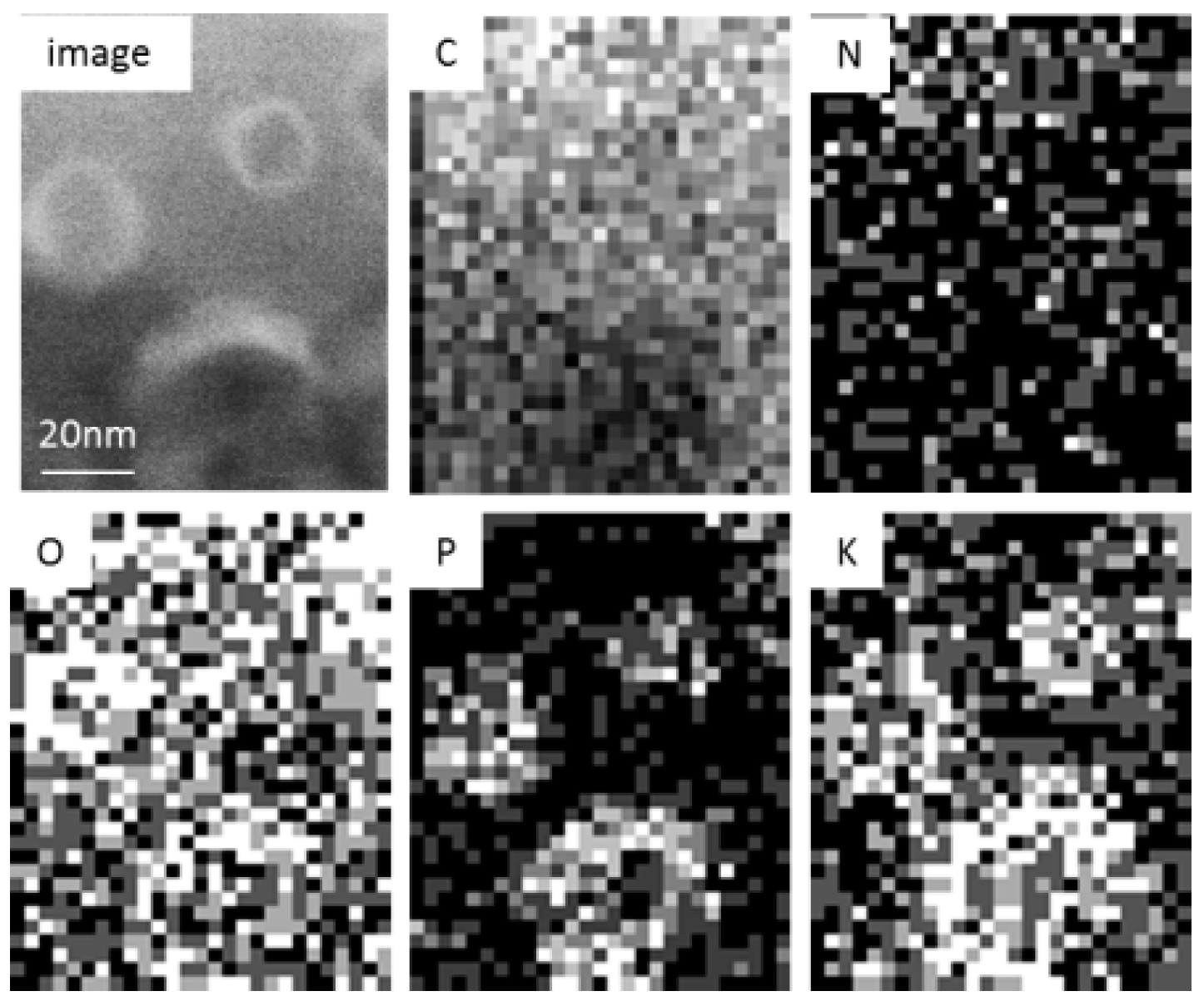
EDX investigations were made of a small number of the pits/craters on the substrate shown in Figure 4b. This fragment of material was stable enough to generate rapid EDX maps taking around 8 min, and these are shown for C, N, O, P, and K in Figure 7. The signal to noise ratio of the data generating the maps is poor, for the reasons outlined earlier, but the maps clearly show that P and K are localized to the rim of the pits/craters. The oxygen concentration also appears to be slightly higher in those regions where P and K are the highest.
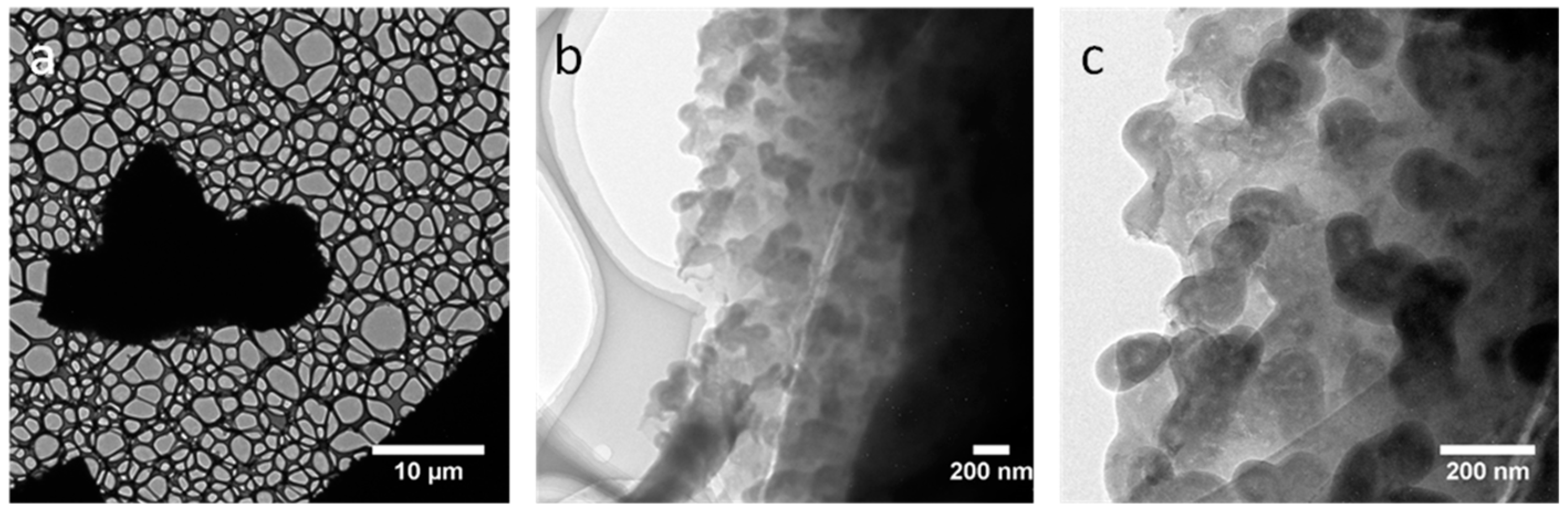
For a weaker combustion of raw spaghetti, such as in Sample 1b, when the stick was burned outside the candle and expected to yield lower temperatures and slower kinetics, we obtained fingers that were more contorted and less stretched out from the substrate. Figure 8a shows a large fragment of the carbonized material held firm between the carbon films of two copper grids while (b) and (c) show examples of the contorted fingers.
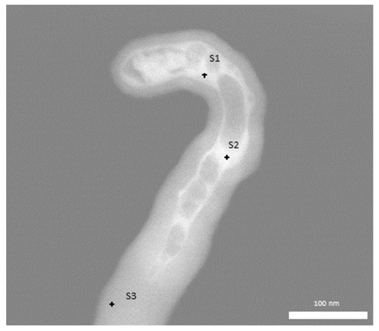
The observation that burning the “raw” material for Sample 1 lead to an enrichment of K and P in the central spine and tip regions of the fingers prompted us to examine a further sample (Sample 2), where the material had been additionally treated by boiling in salt water (3% mass), i.e., similar to the conditions for cooking pasta in domestic use. We cooked the pasta in the salt water for 15 min and let it dry on aluminum foil for 24 h. After combustion, Sample 2 again presented fingers, as can be seen in the dark field STEM image of Figure 9. Points are marked where EDX measurements were performed, with results reported in Table 2.
We again found a shell composed mainly of carbon, with some nitrogen and oxygen. Na and P were concentrated in the neck of the finger, a region where in the untreated burnt pasta we found K and P enrichment. A lower than expected level of chlorine is hard to explain at this stage, but may be due to chlorine gas evaporation in the electron beam.
4. Discussion
Through straightforward combustion, we have been able to produce heterogeneous finger-like carbon structures with a high degree of cylindrical structure that also present a strongly carbonized outer-shell structure and more loose or hollow internal structure containing ionic species and salts with the main elements being C, O, H, N, K, and P, with additional Na when the pasta was cooked in salted water. H is assumed to be present, even though it cannot be detected by EDX. EDX shows also that the local ratio of elemental concentrations between O and P is around 4 to 1, and this proportion may indicate the presence of phosphates, including H2PO4− ions. Bicarbonate ions, e.g., HCO3−, however, may also be present.
The overall composition of “Pasta, cooked, unenriched, without added salt”, (i.e., NaCl), is reported in the National Nutrient Database of the United States Department of Agriculture [15]. The data include P and K at around the 50 mg/100 g level, while Na and Cl are at or below the 1 mg/100 g level. Our attempt to investigate the raw unburnt spaghetti with TEM and EDX in this study was complicated by a breakdown of the structure in the electron beam and the oxygen signal dropping in seconds. Nevertheless, we found clearly defined X-ray peaks for P and K, with an estimated concentration of around 0.1–0.25% (atomic), but not for other minerals such as Na and Cl. These low values of P and K in the unburnt material compared to values in the tips or inner regions of the fingers in the burnt material demonstrate the concentrating effect that combustion has. Organic matter and material containing water generally demand specialist TEM techniques, such as cryomicroscopy, to prevent damage and water evaporation, but future investigations of this nature may be helpful for understanding properly the nature of our “starting material” and the inhomogeneities that would be expected in pasta.
The method to obtain the structures was very simple. First, there is the ignition of one end of a spaghetti stick by a candle flame. Then, the candle flame can continue to support combustion during propagation through the unburnt material, or the combustion can continue unsupported, producing a weak flame and lower temperature combustion. In the candle flame-supported combustion, we generally obtained straight fingers, while in the self-sustaining combustion condition, we obtained more twisted structures (compare Figure 3, Figure 4, Figure 5 and Figure 6 with Figure 8). The flame spread velocity was 0.5–1 mm/s.
Figure 10 shows a single photograph of a freely burning stick, in which four different characteristic regions were observed at the same moment. In Region 1, there is pristine or unburnt material. In Region 2, combustion has just started. We see a flame region where off-gassing at the surface produced a blue flame with a weak slightly yellow tip, leaving behind a black surface. In Region 3, combustion has proceeded and the incandescent red-orange region shows high temperature pyrolysis (HTP) inside. Finally, in Region 4 we have the post-HTP region producing fumes or smoke (appearing yellow in the picture from light scattered by the fumes). The temperature of the HTP region was estimated to reach about 1000 °C, using the thermocouple in contact with the glowing surface. The entire reaction cycle was less than one-minute long.
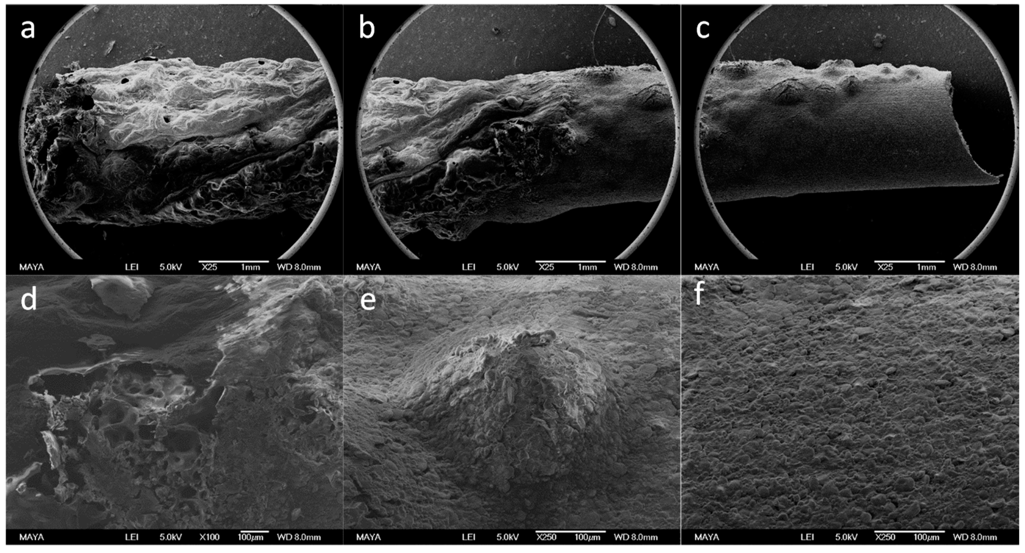
For more information on the structural changes for the burning processes, see Figure 11. It shows SEM images obtained at the different positions of a stick: (a) burnt; (b) transition regions, where surface has not yet blackened; and (c) partially heated (upper left) and virtually unaffected surface (lower right of the stick). Figure 11d shows the parts (with higher resolution) of a broken surface in the transition region, which is rich in internal macropores, indicating the considerable amounts of gas developed from the breakdown of polysaccharides; (e) volcanic structures with diameters around a few hundreds of micrometers, and (f) raw material corresponding to the transition and unburned upper left and lower right of Figure 11c, respectively.
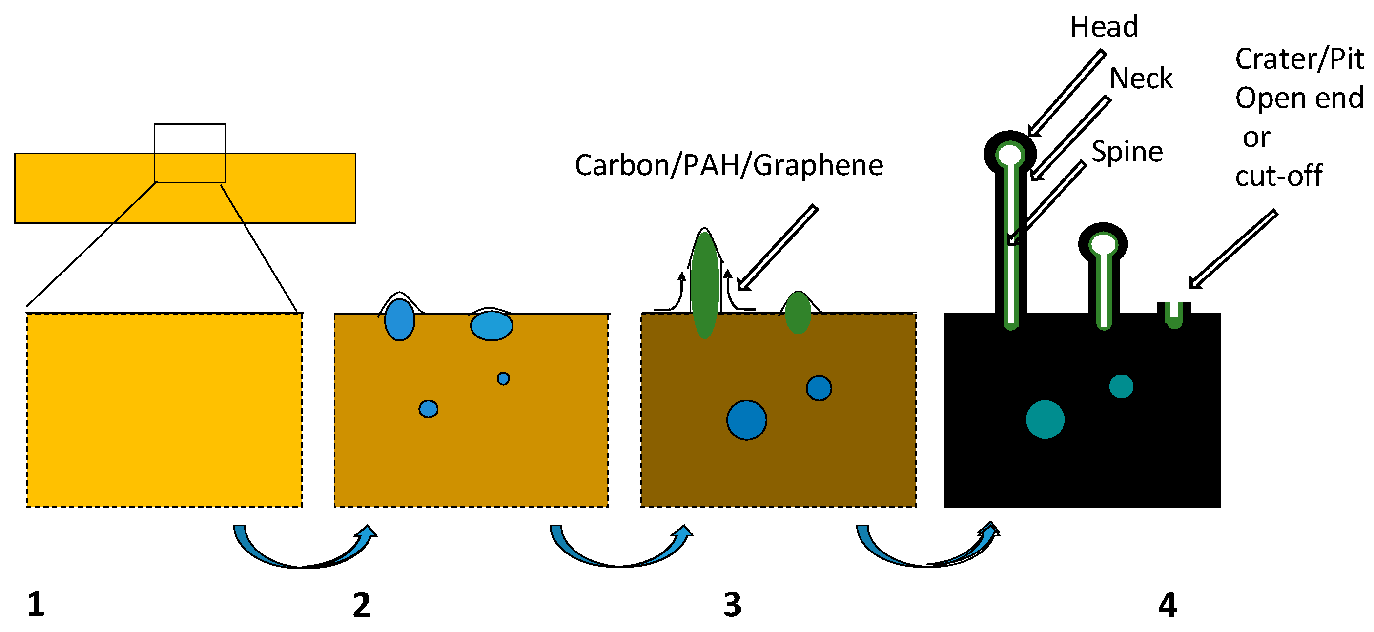
Based on the observations from SEM, TEM, EDX, and photographs of the burning stick, we propose the following scheme for the combustion of the spaghetti sticks. At first, and as seen in Region 2 of Figure 10, thermal degradation of the bio-saccharides at the surface releases flammable gases that sustain the flame. At the same time, there is an enrichment of carbon and aromatic and polycyclic aromatic hydrocarbon (PAH) structures that increase in size (see, e.g., [16]). These structures probably stack together, but rather loosely so that they may glide one upon the other. Heat from the gas phase and the surface is transferred to the inside of the stick, where the increased temperature allows oxidant-free pyrolysis to occur and gases are produced. When the HTP reaction state is reached, seen in Region 3 of Figure 10, the finger-like structures can be expected to be formed, as follows. The bulk probably assumes a heterogeneous structure including gas, liquid, and solid states, which have different chemistries and polarity regions. Due to the pressure rise from the formation and heating of gas, bubbles can form and propagate to the surface. The viscous PAH layers form a barrier at the surface. The gas bubbles develop into pressurized pockets, which finally erupt through the surface, carrying with them material that subsequently forms the finger-like structures. This concept is different from the one usually described by chemical vapor deposition (CVD) and catalytic growth [17,18,19], and different also from a stepwise structural formation of tubular-like structures via a self-assembly of spherical particles [9]. Any soot particles from the flame region would be unlikely to diffuse upstream to the region closest to the surface (i.e., to within a few micrometers) of the stick where the fingers are formed, i.e., would be unlikely to flow in the opposite direction to the gas being expelled. For the case where PAH layers are less strong, the gases may escape through crater-like hollow openings. The bulk is about 1000 times denser than that of the gas phase outside the surface, so that the supply of precursors from the bulk to the surface should dictate the kinetic rates and dynamics of nanostructure formation into fingers, if the temperature is sufficiently high. As the carbonization continues, the layers will contain less hydrogen and oxygen and become more rigid, leaving meanders of pores or voids that extend to the surface. Through these channels, gases can more easily escape and be seen as fumes when they exit the burning stick, see Region 4 in Figure 10. A schematic illustration of the formation of bubbles and finger and crater-like structures is given in Figure 12.
In Stages 1 to 3, temperatures increase and can reach those typically found for hydrothermal carbonization, i.e., below 300 °C [6]. Spherical structures have been reported for HTC by other groups (see [7] and references therein) on biomass studies, but researchers have not yet investigated the earlier stages in detail, as in our case. As the temperature is increased into the main pyrolysis stage of Region 3, the amount of gas and water being formed is expected to rapidly increase and it can be expected that there will be a separation of phases of polar (water, alkali, and other ionic species) and nonpolar (mostly carbon) substances. As carbon substances develop from the decomposing biomass, they will acquire a high degree of sp2 hybridization and form PAH/nano-sized graphene-like lamellae. These lamellae can be electrically conductive within and may slide across each other. As the lamella become more flat and graphene-like, they will eventually stack and cross-link at sp3 hybridized local sites. At these sites in the nano-sheets, –OH and COOH groups can interact and undergo condensation reactions, producing H2O and leading to the cross-linking. This linking of the sheets would inhibit the diffusion of water out of the finger-like structures, causing the internal pressure to increase and the finger to continue to grow. The carbon film leading to the final carbon shell thus would expand from the rising pressure of vapor, resembling glass blowing or volcanic activity, where the carbon behaves as the glass or earth’s crust, respectively. In the final stages, the water will diffuse out slowly, leaving a salty slurry of alkali and phosphates inside the finger that eventually will stick to the inner walls of the carbon shell. This carbon shell may be rich in OH and –COO− groups and therefore attract charged or polar compounds. Alongside the fingers, other structures may also be formed as pits and craters (i.e., no growth of tubular walls) during the heating up process and pyrolysis. On the other hand, no features resembling pits or craters were observed in SEM, and those we studied in TEM corresponded in size and composition to the fingers. Hence, those TEM-observed features could be the remaining base of fingers that broke off the substrate when handled before microscopy. Although CVD-like processes and transformation of self-assembled particles into tubular structures [9] cannot be excluded for finger formation, in our case we would suggest the dynamics outlined and illustrated in Figure 12 to be more probable.
In summary, the fingers appear to be formed in the HTP region, where temperatures in the bulk and the surface are high enough to give the material at the surface almost liquid-like properties for the carbon. Due to the high internal gas and density pressure from inside the bulk, the kinetic rates for finger formation should be driven from below the surface. Due to the constant flow of gas out of the stick, which aliments the flame, soot particles would be unable to diffuse upstream towards the surface where the fingers are growing. This hypothesis is strengthened by the fact that we find enrichment of Na (which is soluble in water or in the polar environment inside the fingers) on the inside of the fingers.
Many interesting research areas open up from the phenomena described here, such as a study of the dependence of the finger structure on flame temperature, pyrolysis temperature, or stick material composition. Various future applications may be envisioned or proposed conceptually, such as: (1) heterogeneous nanoscale reactors with catalytic properties on the inside of open tubes, (2) traps for harmful waste, e.g., heavy metal ions, toxic, and radioactive ions to be isolated from the environment, (3) magnetic elongated nanoparticles for remote control of transportation or rotation, and (4) high-surface-to-volume microelectrode structures for some applications and nano-electronic/ionic interfaces with biological cells.
5. Conclusions
In this study, we have shown how finger-like heterogeneous carbon nano-structures can be easily formed from the burning of spaghetti. We have also found a spatial differentiation of non-polar compounds in the outer shell and polar compounds in the interior of the fingers. The outer shell contains the highest amount of carbon, while the interior, sometimes formed as an inner shell, contains polar alkali metal species together with phosphorous-rich compounds, probably phosphates. In the case of spaghetti cooked in salt water, the shell structures appear to be more stable to electron beam radiation compared to the inner parts, which contained sodium. It would be interesting to continue the study on different water-soluble metal salts with different states of oxidation in order to produce metal-carbon hybrid finger structures with diverse electric, magnetic, and electromagnetic properties.
Author Contributions
The initial concept for the study came from F.O.; sample carbonization was performed by F.O.; preparation of the microscope samples and the microscopy was performed by C.J.D.H; Analysis of data C.J.D.H and F.O.; Preparation of manuscript F.O. and C.J.D.H.
Funding
We acknowledge nCHREM, the Centre for Combustion Science and Technology (CECOST) and the Generic Research for Optimized Energy Conversion Processes (GRECOP), project number 38913-2, supported by the Swedish Energy Agency. The project was also supported by the Lund Laser Centre (LLC).
Acknowledgments
Access to the microscopes was facilitated by the “Atomic Resolution Cluster”, a research infrastructure funded by the Swedish Foundation for Strategic Research.
Conflicts of Interest
The authors declare no conflict of interest.
References
- Creasy, W.R.; Zimmerman, J.A.; Ruoff, R.S. Fullerene Molecular Weight Distributions in Graphite Soot Extractions Measured by Laser Desorption Fourier Transform Mass Spectrometry. J. Phys. Chem. 1993, 97, 973–979. [Google Scholar] [CrossRef]
- Grieco, W.J.; Howard, J.B.; Rainey, L.C.; Vander Sande, J.B. Fullerenic carbon in combustion-generated soot. Carbon 2000, 38, 597–614. [Google Scholar] [CrossRef]
- Murr, L.E.; Soto, K.F. A TEM study of soot, carbon nanotubes, and related fullerene nanopolyhedra in common fuel-gas combustion sources. Mater. Charact. 2005, 55, 50–65. [Google Scholar] [CrossRef]
- Ossler, F.; Wagner, J.B.; Canton, S.E.; Wallenberg, L.R. Sheet-like carbon particles with graphene structures obtained from a Bunsen flame. Carbon 2010, 48, 4203–4206. [Google Scholar] [CrossRef]
- Ossler, F.; Canton, S.E.; Wallenberg, L.R.; Engdahl, A.; Seifert, S.; Hessler, J.P.; Tranter, R.S. Measurements of structures and concentrations of carbon particle species in premixed flames by the use of in-situ wide angle X-ray scattering. Carbon 2016, 96, 782–798. [Google Scholar] [CrossRef] [Green Version]
- Deng, J.; Li, M.; Wang, Y. Biomass-derived carbon: Synthesis and applications in energy storage and conversion. Green Chem. 2016, 18, 4824–4854. [Google Scholar] [CrossRef]
- Titirici, M.-M.; Thomas, A.; Antonietti, M. Back in the black: Hydrothermal carbonization of plant material as an efficient chemical process to treat the CO2 problem? New J. Chem. 2007, 31, 787–789. [Google Scholar] [CrossRef]
- Falco, C.; Baccile, N.; Titirici, M.-M. Morphological and structural differences between glucose, cellulose and lignocellulosic biomass derived hydrothermal carbons. Green Chem. 2011, 13, 3273–3281. [Google Scholar] [CrossRef]
- Shi, K.; Yan, J.; Lester, E.; Wu, T. Catalyst-free synthesis of multiwalled carbon nanotubes via microwave-induced processing of biomas. Ind. Eng. Chem. Res. 2014, 53, 15012–15019. [Google Scholar] [CrossRef]
- Zhu, J.; Jia, J.; Kwong, F.L.; Ng, D.H.L.; Tjong, S.C. Synthesis of multiwalled carbon nanotubes from bamboo charcoal and the roles of minerals on their growth. Biomass Bioenergy 2012, 36, 12–19. [Google Scholar] [CrossRef]
- Harris, P.J. Transmission electron microscopy of Carbon: A brief history (Review). C J. Carbon Res. 2018, 4, 4. [Google Scholar] [CrossRef]
- Tahaeri, M.L.; Stach, E.A.; Arslan, I.; Crozier, P.A.; Kabius, B.C.; LaGrange, T.; Minor, A.M.; Takeda, S.; Tanase, M.; Wagner, J.B.; et al. Current status and future directions for in-situ transmission electron microscopy (Review article). Ultramicroscopy 2016, 170, 86–95. [Google Scholar] [CrossRef] [PubMed]
- Su, D. Advanced electron microscopy characterization of nanomaterials for catalysis. Green Energy Environ. 2017, 2, 70–83. [Google Scholar] [CrossRef]
- Gao, Z.; Song, N.; Zhang, Y.; Schwab, Y.; He, J.; Li, X. Carbon nanotubes derived from yeast-fermented wheat flour and their energy storage application. ACS Sustain. Chem. Eng. 2018, 6, 11386–11396. [Google Scholar] [CrossRef]
- Basic Report: 20421, Pasta, Cooked, Unenriched, without Added Salt, National Nutrient Database for Standard Reference Legacy Release; United States Department of Agriculture, Agricultural Research Service: Washington, DC, USA. Available online: https://ndb.nal.usda.gov/ndb/foods/show/20421 (accessed on 22 January 2019).
- Herring, A.M.; McKinnon, J.T.; Petrick, D.E.; Gneshin, K.W.; Filley, J.; McCloskey, B.D. Detection of reactive intermediates during laser pyrolysis of cellulose char by molecular beam mass spectroscopy, implications for the formation of polycyclic aromatic hydrocarbons. J. Anal. Appl. Pyrolysis 2003, 66, 165–182. [Google Scholar] [CrossRef]
- Huang, Z.-H.; Zhang, F.; Wang, M.X.; Lv, R.; Kang, F. Growth of carbon nanotubes on low-cost bamboo charcoal for Pb(II) removal from aqueous solution. Chem. Eng. J. 2012, 184, 193–197. [Google Scholar] [CrossRef]
- Zhu, J.; Jia, J.; Kwong, F.-L.; Ng, D.H.L.; Crozier, P.A. Metal-free synthesis of carbon nanotubes filled with calcium silicate. Carbon 2012, 50, 2666–2674. [Google Scholar] [CrossRef]
- Zhu, J.; Jia, J.; Kwong, F.-L.; Ng, D.H.L. Synthesis of bamboo-like carbon nanotubes on a copper foil by catalytic chemical vapor deposition from ethanol. Carbon 2012, 50, 2504–2512. [Google Scholar] [CrossRef]
Figure 1.
A stick of spaghetti being carbonized from combustion. (a) Stick of spaghetti being ignited in a candle flame; (b) the stick lies outside the flame and undergoes self-combustion.
Figure 1.
A stick of spaghetti being carbonized from combustion. (a) Stick of spaghetti being ignited in a candle flame; (b) the stick lies outside the flame and undergoes self-combustion.

Figure 2.
SEM images taken at 10kV of the carbonized stick surface. A sequence of SEM images, taken at increasing magnifications, showing the structures found on the burnt Sample 1a. In (a) we observed the full width of the stick; in (b) lighter patches, which contained nanostructures; (c) showed protruding nanostructures where the surface plane was “edge-on” to the beam; and in (d) a nanostructure “forest” observed in standard plan view.

Figure 3.
TEM images of carbon fingers. (a) TEM image of worm-like fingers; (b) TEM image of broken fingers in a cluster.
Figure 3.
TEM images of carbon fingers. (a) TEM image of worm-like fingers; (b) TEM image of broken fingers in a cluster.

Figure 4.
STEM images of finger and substrate. STEM dark field images of (a) fingers attached to substrate; (b) pits and craters.
Figure 4.
STEM images of finger and substrate. STEM dark field images of (a) fingers attached to substrate; (b) pits and craters.

Figure 5.
High resolution transmission electron microscopy (HRTEM) image analysis of a fingertip carbon shell. (a) Area of a finger-end, showing partially layered carbon structures closely parallel to the direction of the inner and outer surfaces of the fingertip; (b,c) highlights showing selected area with a fringe spacing of 0.42 nm.

Figure 6.
STEM dark field and EDX analysis of a carbon finger. (a) STEM dark field image, showing 3 points at tip/core (left) where EDX data was collected, and 2 points at shell (right). (b) STEM dark field image of structure seen in Figure 5, the small arrow indicates the small drift during the EDX acquisition; (c) shows the corresponding EDX line scans for C, K, and P along the line marked in (b).

Figure 7.
STEM dark field image and corresponding EDX elemental maps of a substrate surface. Top left is the STEM image of 3 “pits” (from lower left part of Figure 4b) and followed by the corresponding EDX maps for different elements.
Figure 7.
STEM dark field image and corresponding EDX elemental maps of a substrate surface. Top left is the STEM image of 3 “pits” (from lower left part of Figure 4b) and followed by the corresponding EDX maps for different elements.

Figure 8.
Electron microscopy images of carbonized material obtained at a lower flame temperature. Lower temperature burning, as in Sample 1b, leads to higher level of tortuosity, probably due to slower growth of fingers. Pictures are shown in order of increased magnification. (a) A piece of combusted spaghetti between two grids; (b,c) twisted fingers at the surface of the carbonized biomass.

Figure 9.
Dark field STEM image of Sample 2—a carbon finger produced by burning spaghetti that had been boiled in salt water.
Figure 9.
Dark field STEM image of Sample 2—a carbon finger produced by burning spaghetti that had been boiled in salt water.

Figure 10.
A freely burning stick with four regions marked, see text for details. The diameter of the stick was 1.2 mm.
Figure 10.
A freely burning stick with four regions marked, see text for details. The diameter of the stick was 1.2 mm.

Figure 11.
(a) to (c): SEM images taken at 5kV showing regions along a stick that have undergone different stages of combustion, all with a scale marker of 1 mm: (a) burnt end; (b) transition region; and (c) transition (upper left) and unburned material (lower right). (d,f) show details, all with scale marker 100 µm (d) from the broken surface of the partially burned stick; (e) transition region, and (f) unburned material.

Figure 12.
Proposed scheme on the formation of fingers and craters during combustion of spaghetti. Numbers 1 to 4 refer approximately to the corresponding regions marked in Figure 10.
Figure 12.
Proposed scheme on the formation of fingers and craters during combustion of spaghetti. Numbers 1 to 4 refer approximately to the corresponding regions marked in Figure 10.


Table 1.
Elemental composition (atomic%) from EDX of a finger produced by the combustion of a fresh stick of spaghetti (see Figure 6a).
Table 1.
Elemental composition (atomic%) from EDX of a finger produced by the combustion of a fresh stick of spaghetti (see Figure 6a).
| Position * | C | N | O | Na | P | S | Cl | K |
|---|---|---|---|---|---|---|---|---|
| Tip (1) | 77.7 | 2.18 | 14.3 | 0.05 | 2.72 | 0.01 | 0.00 | 3.04 |
| Tip (2) | 79.9 | 2.26 | 12.7 | 0.10 | 2.32 | 0.01 | 0.07 | 2.66 |
| Tip (3) | 79.2 | 0.91 | 13.9 | 0.16 | 3.29 | 0.04 | 0.03 | 2.51 |
| Shell (4) | 93.8 | 1.43 | 4.21 | 0.00 | 0.20 | 0.03 | 0.05 | 0.29 |
| Shell (5) | 93.1 | 2.04 | 4.38 | 0.06 | 0.16 | 0.02 | 0.02 | 0.22 |
* Position is given in the order of (1)–(5) as pointed by the arrows given in Figure 6a from the left to right of the corresponding STEM image.
Table 2.
Elemental composition (atomic%) in finger originating from combusted spaghetti previously cooked in salt water—Sample 2 (See Figure 9).
Table 2.
Elemental composition (atomic%) in finger originating from combusted spaghetti previously cooked in salt water—Sample 2 (See Figure 9).
| Position | C | N | O | Na | P | S | Cl | K |
|---|---|---|---|---|---|---|---|---|
| Inner tip (S1) | 69.1 | 0.00 | 21.5 | 0.89 | 7.25 | 0.02 | 0.83 | 0.47 |
| Neck (S2) | 65.9 | 2.13 | 18.8 | 6.32 | 5.61 | 0.47 | 0.20 | 0.49 |
| Shell (S3) | 92.4 | 2.12 | 5.24 | 0.02 | 0.00 | 0.14 | 0.00 | 0.13 |
© 2019 by the authors. Licensee MDPI, Basel, Switzerland. This article is an open access article distributed under the terms and conditions of the Creative Commons Attribution (CC BY) license (http://creativecommons.org/licenses/by/4.0/).
Share and Cite
MDPI and ACS Style
Ossler, F.; Hetherington, C.J.D. Finger-Like Carbon-Based Nanostructures Produced by Combustion of Flour-Based Sticks (Spaghetti). C 2019, 5, 21. https://0-doi-org.brum.beds.ac.uk/10.3390/c5020021
AMA Style
Ossler F, Hetherington CJD. Finger-Like Carbon-Based Nanostructures Produced by Combustion of Flour-Based Sticks (Spaghetti). C. 2019; 5(2):21. https://0-doi-org.brum.beds.ac.uk/10.3390/c5020021
Chicago/Turabian StyleOssler, Frederik, and Crispin J. D. Hetherington. 2019. "Finger-Like Carbon-Based Nanostructures Produced by Combustion of Flour-Based Sticks (Spaghetti)" C 5, no. 2: 21. https://0-doi-org.brum.beds.ac.uk/10.3390/c5020021
Note that from the first issue of 2016, this journal uses article numbers instead of page numbers. See further details here.