Sustainable Recycling of Formic Acid by Bio-Catalytic CO2 Capture and Re-Hydrogenation
by
 and
and
Zhengyang Zhao
1, 
Pei Yu
2,
Bhuvana K. Shanbhag
1,
Phillip Holt
3,
Yu Lin Zhong
4,* and
and
Lizhong He
1,* 1
Department of Chemical Engineering, Monash University, Clayton, VIC 3800, Australia
2
Department of Materials Engineering, Monash University, Clayton, VIC 3800, Australia
3
School of Chemistry, Monash University, Clayton, VIC 3800, Australia
4
Centre for Clean Environment and Energy, School of Environment and Science, Griffith University, Gold Coast Campus, QLD 4222, Australia
*
Authors to whom correspondence should be addressed.
C 2019, 5(2), 22; https://0-doi-org.brum.beds.ac.uk/10.3390/c5020022
Submission received: 22 March 2019
/
Revised: 20 April 2019
/
Accepted: 22 April 2019
/
Published: 1 May 2019
(This article belongs to the Special Issue Advanced Coal, Biomass and Waste Conversion Technologies)
Abstract
:Formic acid (FA) is a promising reservoir for hydrogen storage and distribution. Its dehydrogenation releases CO2 as a by-product, which limits its practical application. A proof of concept for a bio-catalytic system that simultaneously combines the dehydrogenation of formic acid for H2, in-situ capture of CO2 and its re-hydrogenation to reform formic acid is demonstrated. Enzymatic reactions catalyzed by carbonic anhydrase (CA) and formate dehydrogenase (FDH) under ambient condition are applied for in-situ CO2 capture and re-hydrogenation, respectively, to develop a sustainable system. Continuous production of FA from stripped CO2 was achieved at a rate of 40% using FDH combined with sustainable co-factor regeneration achieved by electrochemistry. In this study, the complete cycle of FA dehydrogenation, CO2 capture, and re-hydrogenation of CO2 to FA has been demonstrated in a single system. The proposed bio-catalytic system has the potential to reduce emissions of CO2 during H2 production from FA by effectively using it to recycle FA for continuous energy supply.
1. Introduction
Hydrogen (H2) is considered to be a superior energy source because of its high energy retention efficiency [1]. However, the efficient and safe storage and transport of H2 are major challenges faced by the H2-based energy industries [2,3,4]. Recently, formic acid (FA) has been proposed as a convenient liquid phase carrier of H2 due to its stability under ambient conditions and without compromising on the energy efficiency [2,5,6,7]. Although FA can be facilely dehydrogenated into H2 [7,8,9,10], the emission of the greenhouse gas by-product, CO2, hinders the sustainability of FA application for this purpose.
An ideal solution is to develop a FA/CO2 cycle, which is composed of an in-situ CO2 capture stage and a subsequent re-hydrogenation stage to convert the captured CO2 into FA. Combining the capture and re-hydrogenation stages within the same cycle avoids the emission of CO2 and regenerates fresh FA for continuous energy supply without using excessive carbon sources. This concept has been proposed previously as a prospective energy system [5,11,12] without the emphasis of demonstration.
FA dehydrogenation, the first step of this cycle, has been intensively studied with a focus on improving gas release efficiency in the form of an H2 and CO2 mixture [5,7]. The use of chemical catalysts still remains the state of art for FA dehydrogenation, with research directed towards improving conversion efficiency and perform reactions at room temperature. Two separate studies have reported the complete conversion of FA at room temperature using CrAuPd catalyst on silica surface and PdAuNi alloy nanoparticles supported by graphene nanosheets which have TOF (Turn Over Frequency) values of 730 mol H2 mol catalyst−1 h−1 [13] and 1090 mol H2 mol metal−1 h−1 [14]. Alternatively, metal-free catalysts using dialkyborane derivatives achieve 79% FA conversion with TOF = 4.1 h−1 after 19 h [15]. Recent focus has been on generating low-cost process by using non-precious transition metals (Fe, Co, Ni) immobilized on metal-organic frameworks (MOFs) with 100% H2 selectivity and a TOF value of 347 h−1 [16]
Separately, several chemical catalytic reactions routes have been demonstrated to convert CO2 to FA with application in H2 production [5]. However, the combination of in-situ CO2 capture from FA dehydrogenation has not been investigated. From previous studies of enzymatic CO2 capture from the atmosphere [17,18,19], carbonic anhydrase (CA), was demonstrated as a sustainable and efficient biocatalyst for CO2 capture [20,21,22] with options for reuse and recycling [23]. Conventionally, the captured CO2 is converted into calcium carbonate in a solid form after capture for easy storage and transport. Previous studies have utilized metal catalysts and extreme conditions such as high temperature, acidic or alkyl conditions, and high pressures for the CO2 re-hydrogenation into FA [12,21,22,23,24,25,26,27,28]. Recently, formate dehydrogenase (FDH) was demonstrated to be efficient for catalyzing the interconversion between CO2 and formic acid [29,30]. Also, a combination of CA and FDH have been employed for the capture and conversion of CO2 to FA [31]. Nevertheless, the utilization of these two enzymes for the sustainable recycling of FA for H2 production has not been demonstrated.
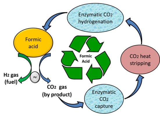
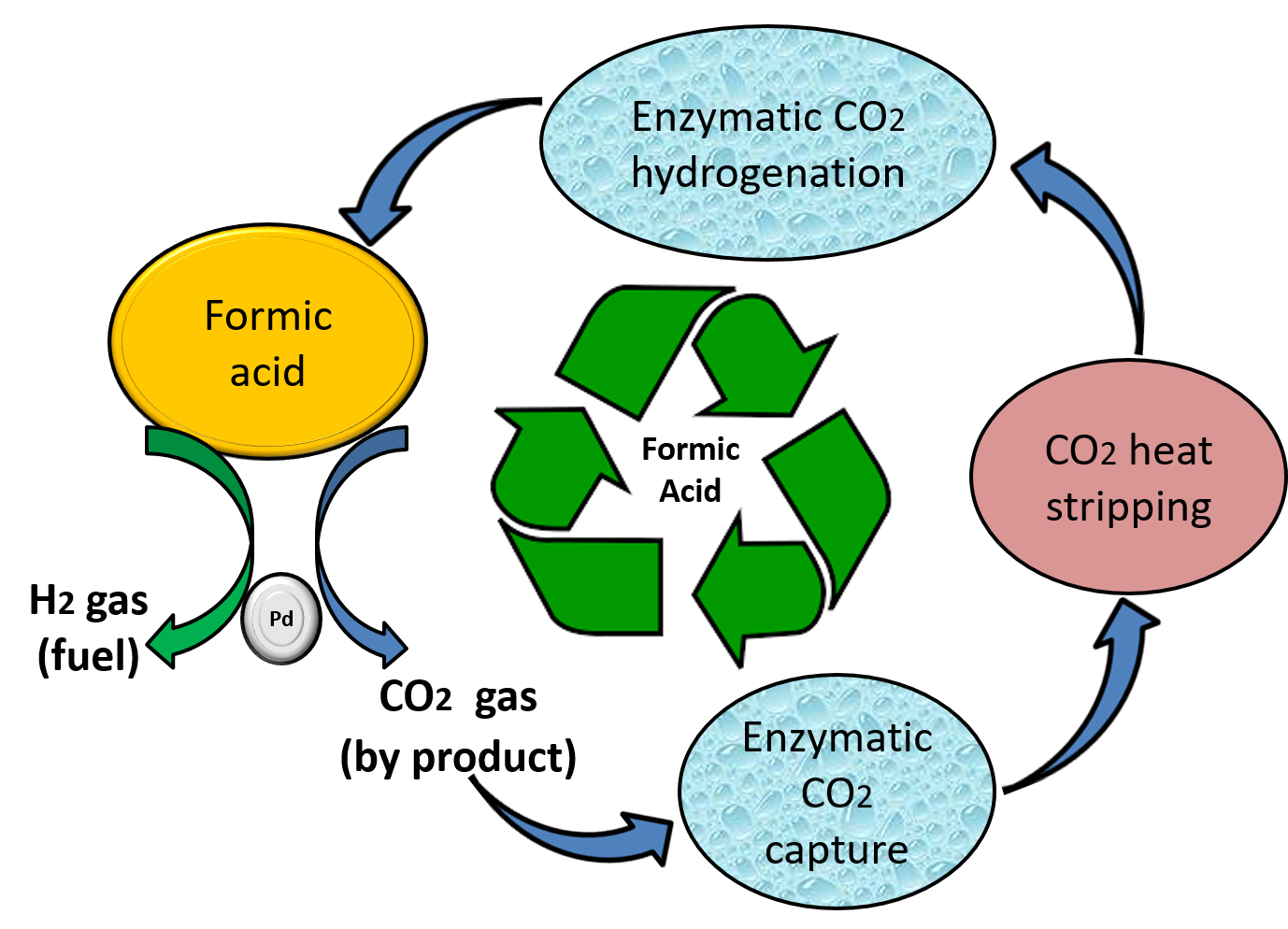
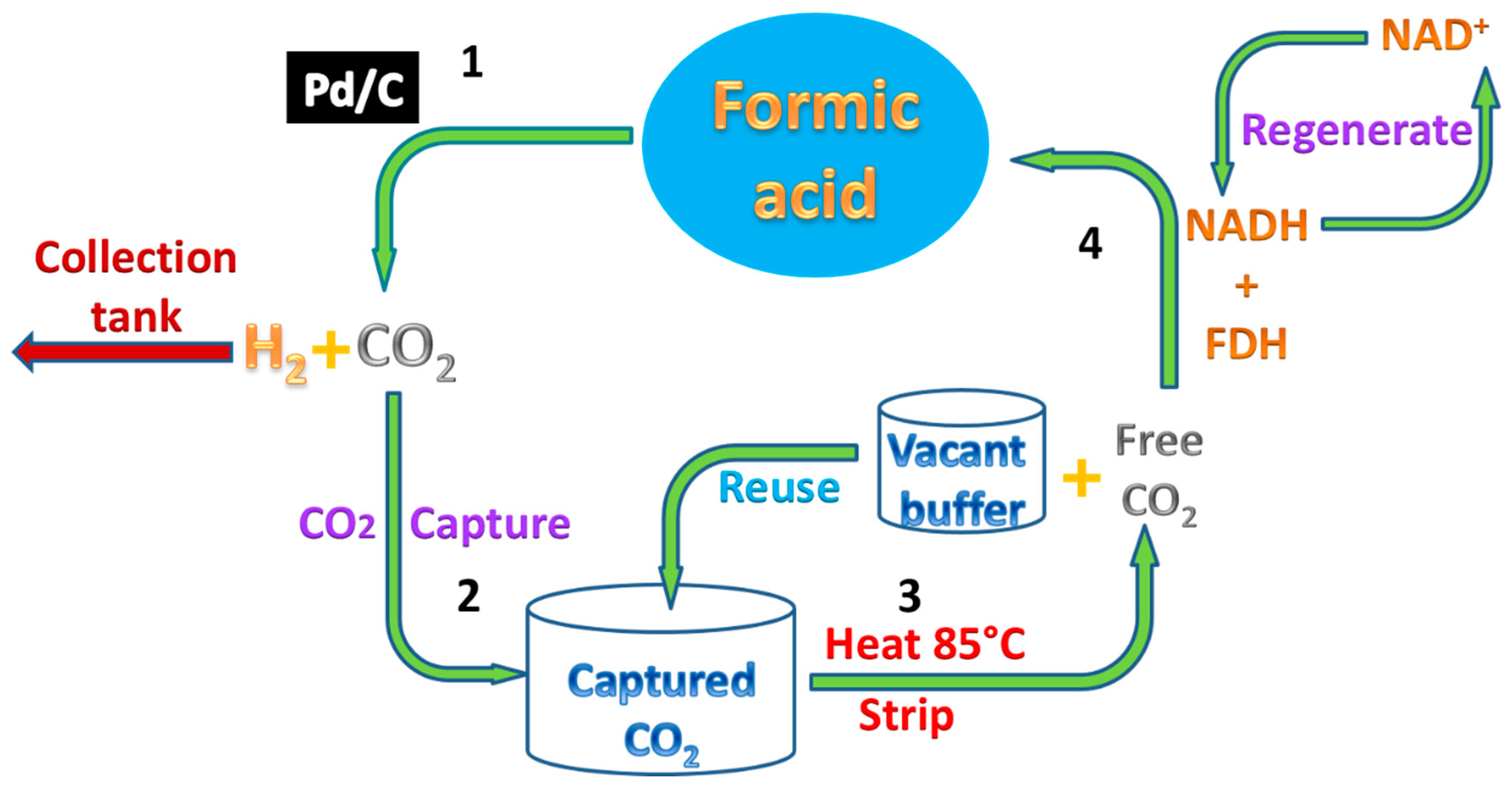
In this study, we demonstrate a proof of concept for the complete FA/CO2 cycle, including in-situ CO2 capture and CO2 re-hydrogenation under ambient conditions using the environmentally-friendly bio-catalytic system, as shown in Scheme 1. In this study, after FA dehydrogenation, the in-situ absorption of the emitted CO2 catalyzed by CA was investigated. After a heat stripping, the captured CO2 was directly re-hydrogenated into formic acid by FDH catalyzed the reaction, with regenerated NADH (Nicotinamide adenine dinucleotide) as a cofactor. In addition, the CA influence on CO2 stripping and the reuse of the absorption buffer were also studied.
2. Materials and Methods
2.1. Materials
Chemicals: All the materials and chemicals were of analytical grade and used as received without further purification. Ethanol amine, sodium carbonate, sodium bicarbonate, Tris-HCl, sodium chloride, imidazole, bromophenol blue, phosphate buffer saline (PBS) tablets, formic acid, Palladium on carbon (Pd/C) (Sigma-Aldrich Sydney, Australia), β-Nicotinamide adenine dinucleotide hydrate (NAD), β-Nicotinamide adenine dinucleotide hydrate reduced salt (NADH), and kanamycin were purchased from Sigma-Aldrich (Sydney, Australia). FDH from Candida boidinii was purchased from Megazyme (Wicklow, Ireland). Enzyme purity was determined using SDS-PAGE 4–12% Bis-Tris Bolt gels and stained with SimplyBlueTM Safe Stain (LC6060, Thermofisher Scientific, Scoresby, VIC, Australia). The pET28a plasmid harboring the bovine carbonic anhydrase gene was a kind gift from A. Prof. Victoria Haritos, used to express and produce CA in E. coli.
2.2. Expression and Purification of CA
The enzyme bovine carbonic anhydrase (CA) was expressed in E. coli BL21 (DE3) cells using Terrific Broth growth media by the Auto–Induction method with 0.2% (v/v) lactose as inducer [32]. Expression cultures were inoculated with 2% (v/v) of inoculum and initially grown at 37 °C at 200 rpm for 3–4 h; followed by protein expression at 20 °C for 16–18 h. Cells were harvested at 10,000 rpm for 10 min and lysed by sonication in lysis buffer (50 mM Tris-HCl pH 8.0, 50 mM NaCl, 1 mM EDTA (Ethylenediaminetetraacetic acid), 0.5% Triton-X100). Following centrifugation, the supernatant was purified by Immobilized Metal Affinity chromatography (IMAC) (Profinity IMAC, Biorad laboratories, Gladesville, NSW, Australia). CA was eluted using 200 mM imidazole in 50 mM Tris-HCl + 0.5 M NaCl pH 8.0 buffer and the pure protein fractions were buffer exchanged (G25 Sephadex, GE Healthcare) against 50 mM Tris-HCl buffer (pH 8.0). Samples were analyzed using 4–12% Bolt Bis–Tris precast gels at 165 V for 40 min and protein bands were stained using SimplyBlueTM Safe Stain.
2.3. FA Decomposition and CO2 Absorption
FA decomposition reaction was conducted by following the method of previous research [33]. The Pd/C catalyst used in this study is a black powder with 10 wt. % Pd loaded on activated carbon, having a boiling point of 2963 °C and a melting point of 1554.69 °C. The Pd/C catalyst (213 mg) was kept in a two-necked round-bottom flask. One neck was connected to a gas-proof cylinder filled with water, and the other was connected to a pressure-equalization funnel to introduce FA aqueous solution (1 M, 10.0 mL). The catalytic reaction was started after the FA solution was added into the flask with magnetic stirring (300 rpm) maintained at ambient temperature (25 °C). The volume of the gas that evolved from the reaction was measured by the reduction of water level in the cylinder. For CO2 absorption, a glass tube filled with 35 mL different buffers (50 mM NaHCO3, 50 mM ethanolamine, and 50 mM NaHCO3 with 3 mL purified CA elution, respectively. The pH of all the buffers were adjusted to 9.5) were added between the flask and the cylinder. Then, the gas was passed through the buffer before collecting into the cylinder. The whole laboratory set-up including FA dehydrogenation and CO2 absorption units is shown schematically as stage-1 in Figure S1.
2.4. CO2 Stripping from Buffers
The stripping of CO2 was conducted by incubating buffers in 85 °C water bath for 15 min with gentle shaking. The volume of stripped gas was measured by a water cylinder, as in Section 2.3. For the stripped CO2 used for hydrogenation, a balloon was connected with buffer flask to collect the stripped CO2 and then moved for hydrogenation (stage-2, Figure S1).
2.5. CO2 Hydrogenation
The CO2 hydrogenation was conducted by following a previous method [34]. Typically, 200 μL FDH was added into 20 mL PBS buffer (0.1 M pH 7.4) containing 4 mM NADH. Then, the balloon with the collected CO2 was plugged into the above buffer flask and incubated at room temperature (stage-3, Figure S1). Samples were taken at regular intervals of 5–10 min up to 1 h for spectrophotometric measurements.
2.6. Electrochemical Regeneration of NADH
The electrochemical regeneration of NADH was conducted by following a previous method [34]. The experiment was conducted in a plastic beaker. Platinum wire (2 cm/10 mL) was used as the anode and copper foil (10 mm2/mL buffer) was used as the cathode. Ag/AgCl electrode was used as reference electrode using a potential of 650 mV. The reaction was purged with argon gas for half an hour before the reaction and purged continuously until the complete regeneration of NADH. Then, the samples were taken at 15, 30, 60, 90, 150 min for spectrophotometric measurements.
2.7. Gas Chromatography and Spectrophotometric Measurements
Gas analyses were performed on GC-7820 with thermal conductivity detector (TCD) and HP-MOLESIEVE column. (Detection limit: ~10 ppm). Hydrogen detection was conducted using Nitrogen as the transport gas at a speed of 3 mL/min with a split ratio of 5:1. The CO2 gas detection was conducted under similar conditions with a split ratio of 4:1. GC analysis of gas samples was performed using two Agilent 7820 Gas Chromatographs with TCD detection. Hydrogen gas was detected on one machine with Agilent HP PLOT Molesieve 26 m × 320 µm × 12 µm column, Nitrogen carrier with a column flow of 2 mL/min. Isothermal condition at 30 degrees C. Inlet in split mode set at 10:1. CO2 gas was detected on the other GC with a short HP PLOT Molesieve 4 m × 320 µm × 0.12 µm column with Helium carrier at 3 mL/min. The isothermal condition was set at 230 degrees C. Inlet in split mode was set at 4:1.
Gas sampling from the collection balloon was performed with a syringe immediately prior to injection into the GC. The NADH was measured with UV-vis absorption by the following method applied in previous research [34].
3. Results and Discussion
3.1. Evaluation of Simultaneous FA Decomposition and CO2 Absorption
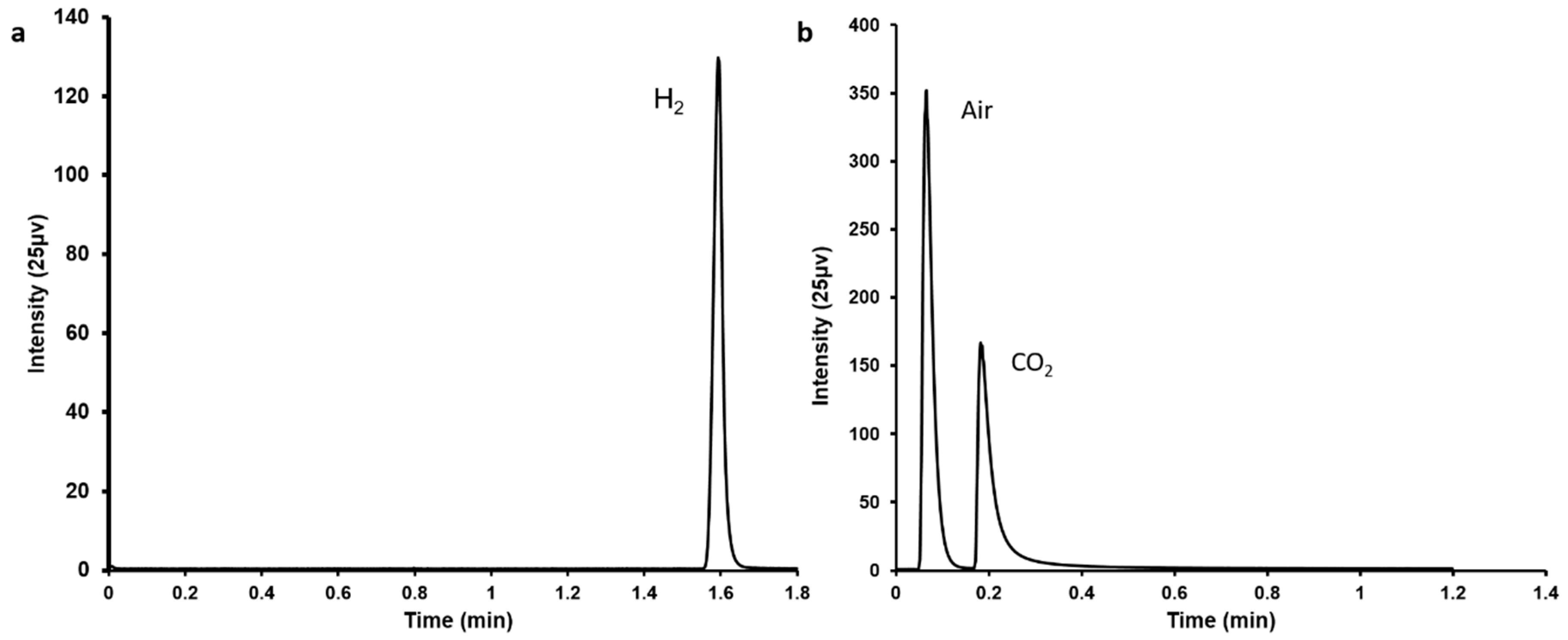
In this study, simultaneous FA decomposition and capture of emitted CO2 were achieved within a single system. A typical Pd/C catalyst [8] was applied for the FA decomposition resulting in the generation of CO2 and H2, which were confirmed by gas chromatography (Figure 1).
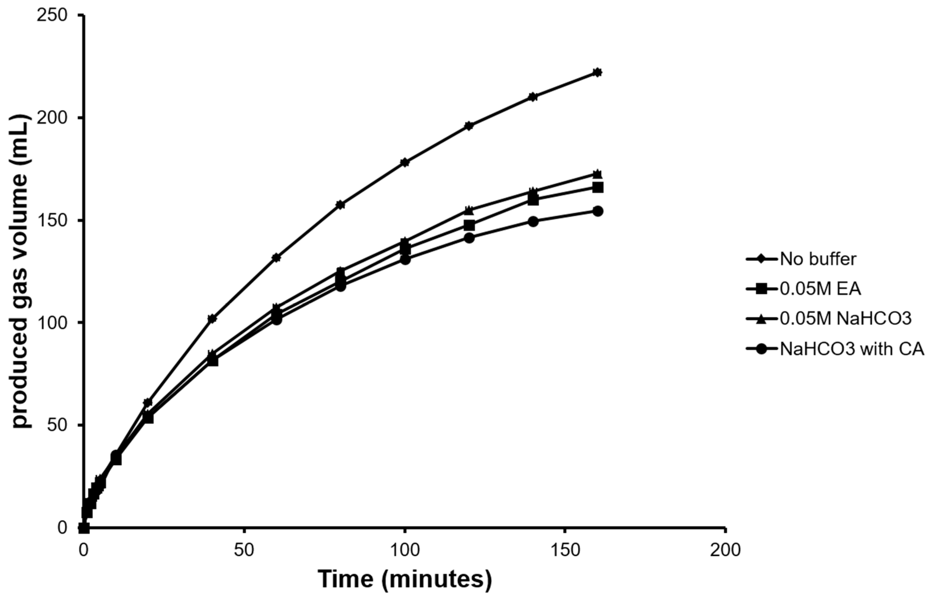
FA decomposition produced a total gas volume (H2 + CO2) of 225 mL with 93 mL of CO2 evolved after a total reaction time of 160 min (Figure 2). To reduce CO2 emission, various buffers were used to capture CO2 and their absorption capacities were evaluated. As a conventional approach, ethanolamine buffer was used as one of the capture solvents in our study due to its high absorptive capacity [35] and popularity in power generation industries [36]. To test the enzymatic CO2 capture, purified CA (Figure S2) dissolved in NaHCO3 buffer along with NaHCO3 buffer alone as control were evaluated in separate experiments. Maximum CO2 capture was achieved when CA in NaHCO3 was used as capture solvent resulting in 26 mL of emitted CO2. This was a 40% reduction in emission when compared to using NaHCO3 buffer alone (emitted CO2 44 mL). Though ethanolamine buffer indicated better absorptive capacity than NaHCO3 buffer alone, the emitted CO2 was higher (37 mL) than the CA buffer (Figure 2).
By incorporating in-situ enzymatic CO2 capture along with FA decomposition, almost three quarters of the CO2 evolved from FA decomposition was captured. The CO2 capture and temporary storage in ionic buffer state allow easy stripping and reuse to further produce compounds such as solid carbonate [37,38,39] as a traditional approach or value-added bulk and fine chemical compounds [40] and even recycling into FA again, as demonstrated in following sections.
3.2. CO2 Strip from Different Buffers after Absorption
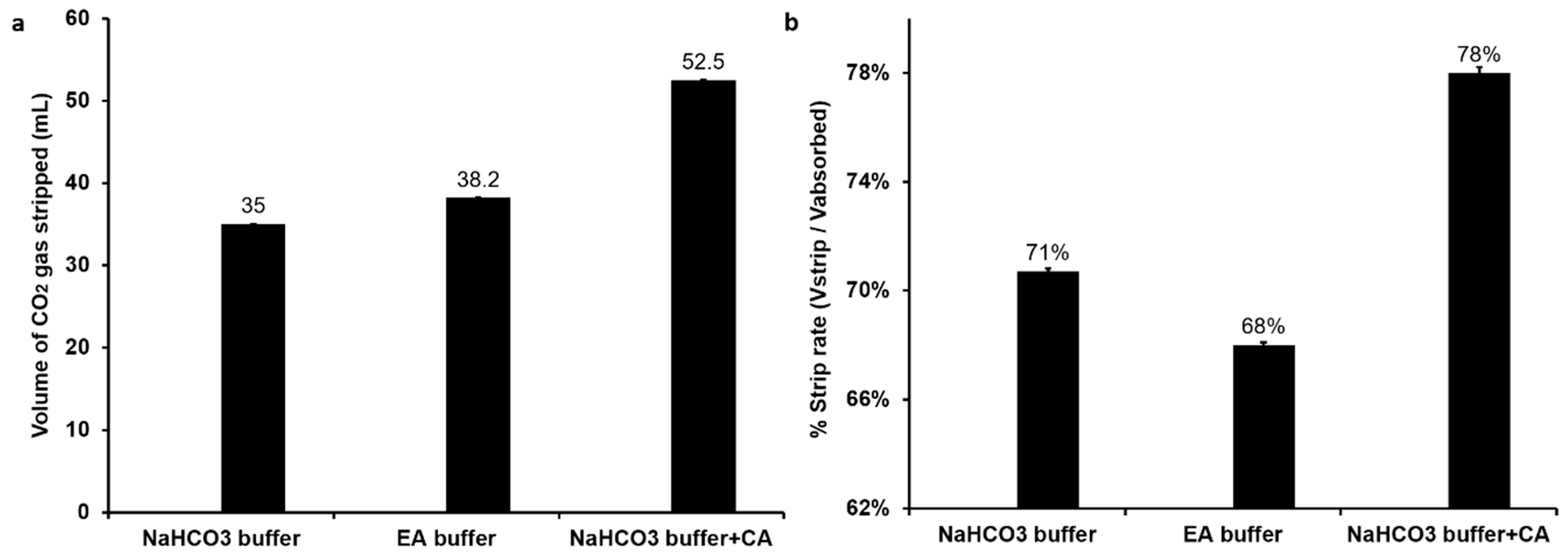
In this study, the CO2 stripping by simple heating method was performed. As demonstrated by Figure 3a, after heating, there was 52.5 mL CO2 stripped from the CA buffer, and the strip rate (Vstrip/Vabsorb) was 78% (Figure 3b). The stripped CO2 from ethanolamine buffer was a few more than that from NaHCO3 buffer, with a volume of 38.2 mL and 35 mL, respectively. However, compared with the CA buffer and NaHCO3 buffer, the strip rate of ethanolamine buffer was the lowest (Figure 3b). After absorption in ethanolamine buffer, CO2 can react with the primary and secondary amine to form amino carbonate [18]. On the other hand, with CA as biocatalyst, the CO2 molecule is captured in buffer under equilibrium between CO2 (aq) molecules and HCO3− anions. Therefore, the restoration of CO2 from ethanolamine buffer requires more energy than from CA buffer. Thus, the strip rate of CA buffer was higher than ethanolamine buffer. As results show, the CA buffer not only indicated the best absorptive capacity, but also revealed the best strip rate. Next, we also investigated the reusability of stripped buffers (Figure S3). Although all buffers indicated reasonable reusability, the CA buffer did not show a significant impact compared with the other two buffers. This can be attributed to the denaturation of CA under high temperature (85 °C) during the stripping process. This has been confirmed in an independent experiment where high-temperature conditions of 50 °C and 85 °C showed a reduction of CA activity by 11% and 80%, respectively (Figure S4). This can be overcome by using thermostable enzymes [41] or by immobilization of enzyme onto solid supports to enhance the stability and ease separation of the enzyme prior to stripping [38,39,42]. Under all these CO2 capture conditions, the production of H2 gas was not influenced (Figure S5).
3.3. Enzymatic Hydrogenation of CO2 Using Formate Dehydrogenase
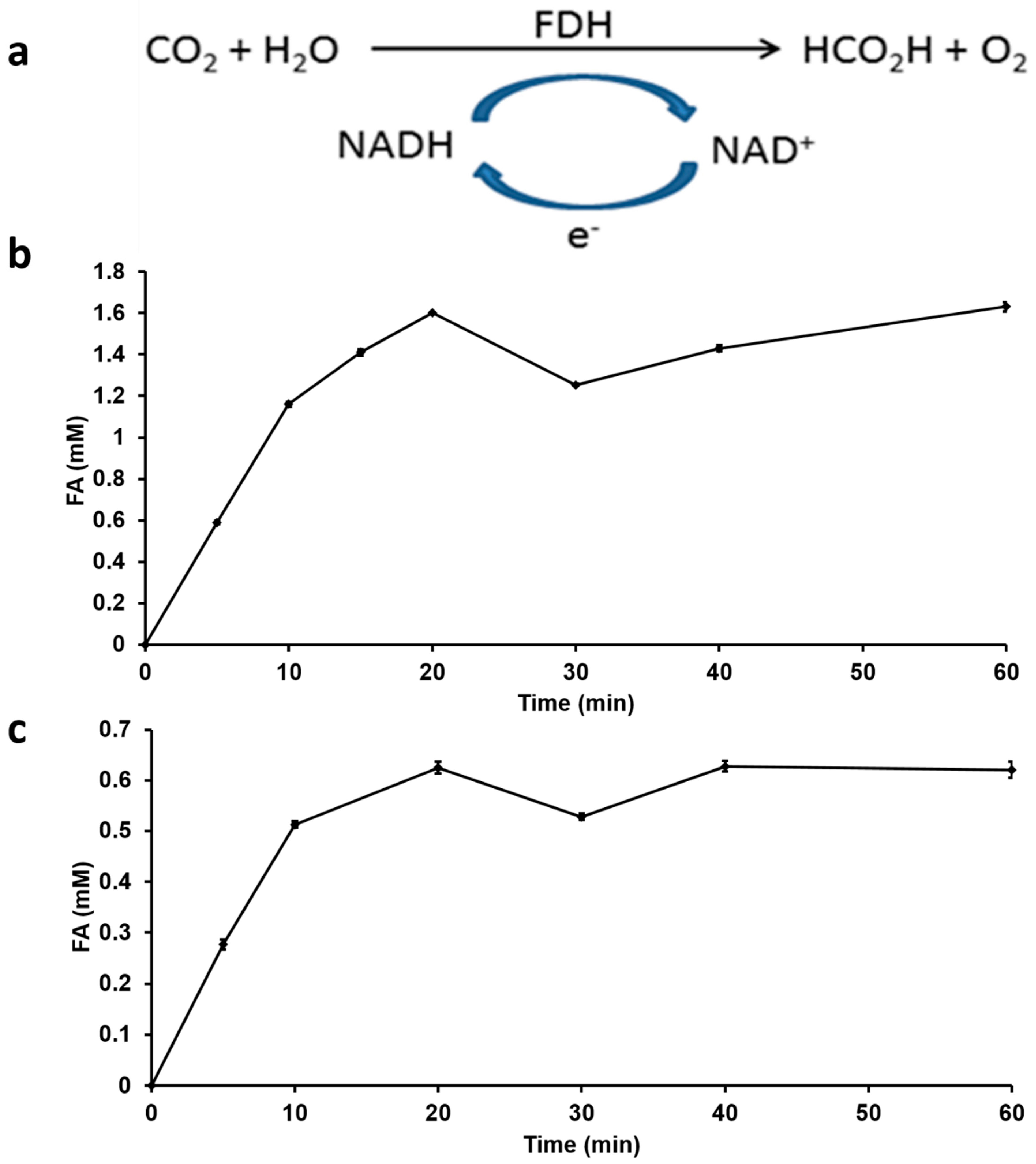
Conventionally, approaches used to convert captured CO2 to FA use either electrochemical or chemical catalytic processes [43,44]. The direct CO2 hydrogenation using chemical catalysts like ruthenium and phosphino-based [25] or iron catalysts [7], requires extreme conditions of temperature and pressure (110 °C and 130 bar) [43]. Direct CO2 hydrogenation to FA also results in the formation of methanol as an additional product [45]. In addition, to the requirement of such extreme conditions, the final FA formed is very dilute and requires additional extraction or distillation steps to obtain pure FA. In nature, formate dehydrogenase enzymes [46] catalyze the reversible interconversion of CO2 and formate under mild conditions of pH and temperature using water as a solvent. In this study, we use FDH with NADH as co-factor for the hydrogenation of captured CO2 (Figure 4a). By directly adding 4 mM NADH as an initial concentration into the reaction mixture, FDH was able to convert captured CO2 into FA with an increase in reaction rate observed during the first 20 min after which it plateaued to a final FA production quantity of 1.6 mM (Figure 4b). For a similar enzymatic CO2 hydrogenation, typical FA product titers of 0.544 g/L and 0.497 g/L for free FDH and immobilized FDH respectively have been reported [31]. Enzymatic reactions are highly selective with minimal by-product formation, therefore by using FDH to hydrogenate CO2, the formation of by-products such as methanol has been avoided thereby improving FA yield in this recycling process for H2 production.
NADH is an essential co-factor for FDH, its efficiency is highly dependent on the NADH concentration as a hydrogen donor. Therefore, its oxidized form (NAD+) must be replenished back to NADH in order to have continued FA production. The regeneration of NADH as a separate step using additional enzymes and substrates can add to the process cost. In order to develop a self-sustaining FA production and recycling system, our approach has incorporated an electrochemical method for NADH regeneration step within the CO2 hydrogenation step. The subsequent reaction releases hydrogen ion by the electrolysis of water using platinum and copper as electrodes using 650 mV of electric potential [34]. It is noteworthy to compare the minimal potential used in our set-up for NADH regeneration as opposed to the conventional requirement of 1.23 V required to produce H2 gas by electrolysis of water [47]. This can significantly reduce costs when considering the design of the electrochemical set-up that can eventually translate to lower H2 gas cost. The reaction profile for FA production with regenerated NADH showed a trend of initial rate increase similar to the process using fresh NADH which was followed by steady FA production (Figure 4c).
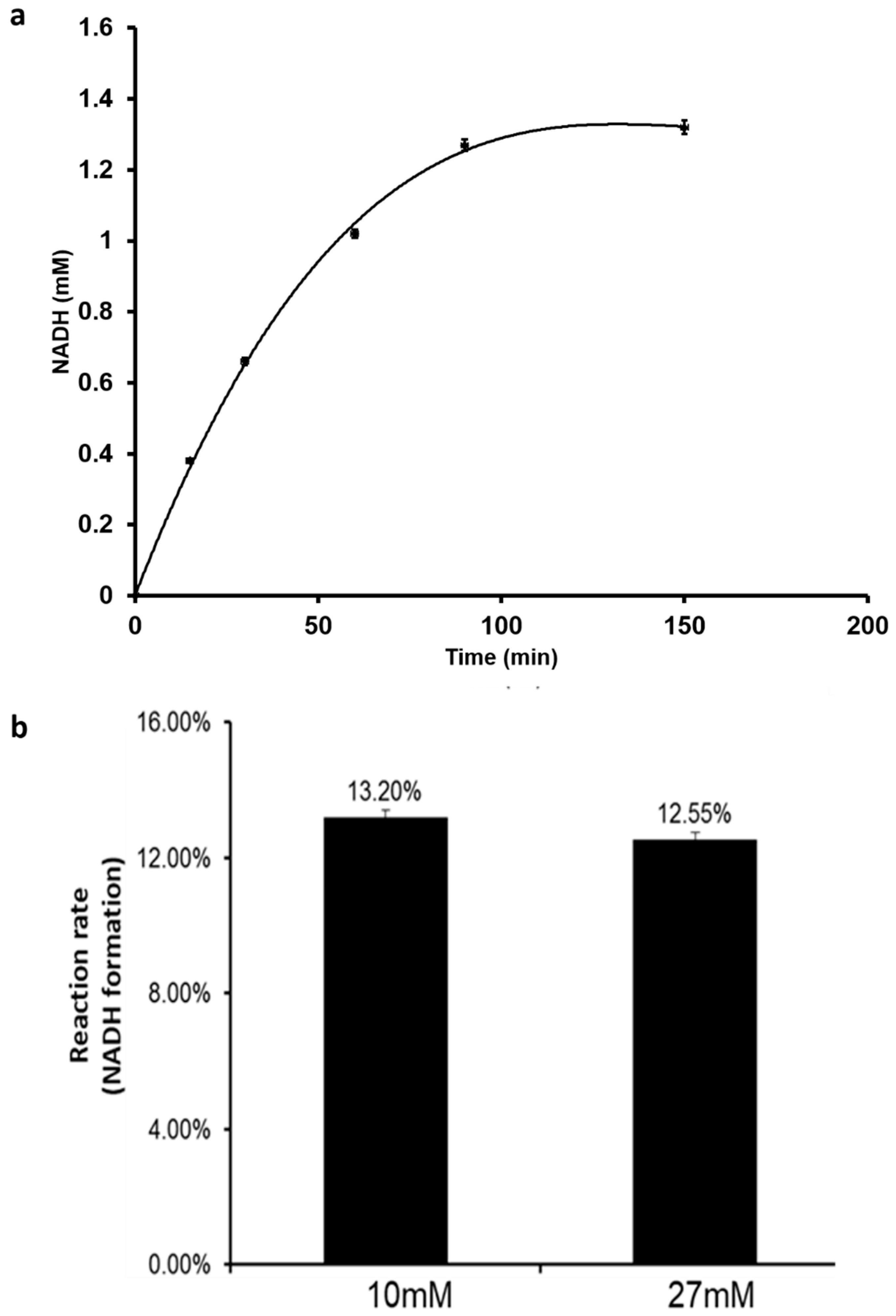
Furthermore, the effect of initial NAD+ concentration on NADH production rate was studied. At NAD+ concentration of 10 mM, the NADH concentration increased continuously until a steady quantity of 1.3 mM was produced (Figure 5a). A further increase of NAD+ initial concentration to 27 mM did not impact the production rate but yielded a higher final NADH concentration of 3.5 mM (Figure 5b). In this way, a constant production rate of NADH can be achieved that continuously feeds FDH for steady FA production. Therefore, by onetime addition of NAD+ to the initial electrochemical set-up and coupling with FDH, the system can become self-sufficient with the net reaction driven towards FA production.
4. Conclusions
In this study, we demonstrate the proof of concept for the complete recycling of formic acid for the H2 gas production process. We have combined chemical, biocatalytic, and electrochemical reactions within a single set-up for efficient formic acid regeneration and reuse. By simultaneous H2 production with in-situ enzymatic CO2 capture, 72% of CO2 produced by formic acid decomposition was efficiently transferred to the next process step. Following heat stripping, 78% of the captured CO2 was recovered and directly fed for hydrogenation into formic acid by FDH. We have achieved the steady in-situ regeneration of NADH by electrolysis of water to boost the efficiency of FDH, an aspect that has great savings for large-scale practical applications since NADH is a high-cost molecule (bulk price per mole—3000 USD) [48] and the stoichiometric supply is not economically viable. Lastly, the entire process has been designed to work under mild reaction conditions with the exception of the CO2 stripping step and therefore could translate to low process costs due to reduced energy consumption. In conclusion, the concept of an environmentally friendly, sustainable, low-cost formic acid recycle has been proposed and demonstrated. We believe this process to have the potential to address some of the impending issues around H2 gas production from FA and to have a positive impact on the economics of H2 as an energy carrier.
Supplementary Materials
The following are available online at https://0-www-mdpi-com.brum.beds.ac.uk/2311-5629/5/2/22/s1. The supplementary information includes Figure S1: Schematic representation of complete laboratory set-up for FA recycle process, Figure S2: SDS-PAGE results of recombinantly expressed and purified CA, Figure S3: Re-absorption capacities of recycled strip buffers, Figure S4: Relative activity of heat treated CA enzyme and methodology for CA activity assay, Figure S5: Gas chromatography profile of H2 formation, Figure S6: Standard curves for quantification of H2, CO2 and air measurements using gas chromatography.
Author Contributions
Conceptualization: Z.Z. and P.Y. Methodology and Experimentation Z.Z., P.Y., B.K.S. and P.H. Analysis and Original draft preparation: Z.Z. Writing—reviewing and editing: B.K.S., Y.L.Z. and L.H. Supervision: Y.L.Z. and L.H. Funding Acquisition: L.H.
Funding
This research was funded by Australian Research Council (ARC) through the ARC Research Hub for Energy-efficient Separation (IH170100009).
Acknowledgments
Z.Z. acknowledges the New Horizon Research Scholarship provided by Faculty of Engineering, Monash University and Commonwealth Scientific and Industrial Research Organization (CSIRO), Australia. Z.Z. and B.K.S. are thankful to Victoria Haritos for providing the plasmid encoding bovine carbonic anhydrase enzyme and her advice on the enzymatic CO2 capture process. L.H. acknowledges the support from the Australian Research Council (ARC) through the ARC Research Hub for Energy-efficient Separation (IH170100009) and the Seed Funding from Faculty of Engineering, Monash University.
Conflicts of Interest
The authors declare no conflict of interest.
References
- Teichmann, D.; Arlt, W.; Wasserscheid, P.; Freymann, R. A future energy supply based on Liquid Organic Hydrogen Carriers (LOHC). Energy Environ. Sci. 2011, 4, 2767–2773. [Google Scholar]
- Grasemann, M.; Laurenczy, G. Formic acid as a hydrogen source—recent developments and future trends. Energy Environ. Sci. 2012, 5, 8171–8181. [Google Scholar] [CrossRef]
- Von Helmolt, U.; Eberle, U. Fuel cell vehicles: Status 2007. J. Power Sources 2007, 165, 833–843. [Google Scholar] [CrossRef]
- Felderhoff, M.; Weidenthaler, C.; von Helmolt, R.; Eberle, U. Hydrogen storage: The remaining scientific and technological challenges. Phys. Chem. Chem. Phys. 2007, 9, 2643–2653. [Google Scholar] [CrossRef]
- Enthaler, S.; von Langermann, J.; Schmidt, T. Carbon dioxide and formic acid-the couple for environmental-friendly hydrogen storage? Energy Environ. Sci. 2010, 3, 1207–1217. [Google Scholar] [CrossRef]
- Johnson, T.C.; Morris, D.J.; Wills, M. Hydrogen generation from formic acid and alcohols using homogeneous catalysts. Chem. Soc. Rev. 2010, 39, 81–88. [Google Scholar] [CrossRef] [PubMed]
- Boddien, A.; Mellmann, D.; Gärtner, F.; Jackstell, R.; Junge, H.; Dyson, P.J.; Laurenczy, G.; Ludwig, R.; Beller, M. Efficient Dehydrogenation of Formic Acid Using an Iron Catalyst. Science 2011, 333, 1733–1736. [Google Scholar] [CrossRef] [PubMed]
- Wang, Z.L.; Yan, J.M.; Ping, Y.; Wang, H.L.; Zheng, W.T.; Jiang, Q. An Efficient CoAuPd/C Catalyst for Hydrogen Generation from Formic Acid at Room Temperature. Angew. Chem. Int. Ed. 2013, 52, 4406–4409. [Google Scholar] [CrossRef]
- De Lacey, A.L.; Fernandez, V.M.; Rousset, M.; Cammack, R. Activation and inactivation of hydrogenase function and the catalytic cycle: Spectroelectrochemical studies. Chem. Rev. 2007, 107, 4304–4330. [Google Scholar] [CrossRef] [PubMed]
- Gu, X.; Lu, Z.H.; Jiang, H.L.; Akita, T.; Xu, Q. Synergistic Catalysis of Metal-Organic Framework-Immobilized Au-Pd Nanoparticles in Dehydrogenation of Formic Acid for Chemical Hydrogen Storage. J. Am. Chem. Soc. 2011, 133, 11822–11825. [Google Scholar] [CrossRef]
- Boddien, A.; Loges, B.; Gärtner, F.; Torborg, C.; Fumino, K.; Junge, H.; Ludwig, R.; Beller, M. Iron-Catalyzed Hydrogen Production from Formic Acid. J. Am. Chem. Soc. 2010, 132, 8924–8934. [Google Scholar] [CrossRef]
- Moret, S.; Dyson, P.J.; Laurenczy, G. Direct synthesis of formic acid from carbon dioxide by hydrogenation in acidic media. Nat. Commun. 2014, 5, 4017. [Google Scholar] [CrossRef]
- Yurderi, M.; Bulut, A.; Caner, N.; Celebi, M.; Kaya, M.; Zahmakiran, M. Amine grafted silica supported CrAuPd alloy nanoparticles: Superb heterogeneous catalysts for the room temperature dehydrogenation of formic acid. Chem. Commun. 2015, 51, 11417. [Google Scholar] [CrossRef]
- Bulut, A.; Yurderi, M.; Kaya, M.; Aydemir, M.; Baysal, A.; Durap, F.; Zahmakiran, M. Amine-functionalized graphene nanosheetsupported PdAuNi alloy nanoparticles: Efficient nanocatalyst for formic acid dehydrogenation. New J. Chem. 2018, 42, 16103. [Google Scholar] [CrossRef]
- Chauvier, C.; Tlili, A.; Gomes, C.D.N.; Thuéry, P.; Cantat, T. Metal-free dehydrogenation of formic acid to H2 and CO2 using boron-based catalysts. Chem. Sci. 2015, 6, 2938. [Google Scholar] [CrossRef]
- Cheng, J.; Gu, X.; Liu, P.; Wang, T.; Su, H. Controlling catalytic dehydrogenation of formic acid over low-cost transition metal-substituted AuPd nanoparticles immobilized by functionalized metal–organic frameworks at room temperature. J. Mater. Chem. A 2016, 4, 16645. [Google Scholar] [CrossRef]
- Lu, Y.; Ye, X.; Zhang, Z.; Khodayari, A.; Djukadi, T. Development of a Carbonate Absorption-Based Process for Post-Combustion CO2 Capture: The Role of Biocatalyst to Promote CO2 Absorption Rate. Energy Procedia 2011, 4, 1286–1293. [Google Scholar] [CrossRef]
- Li, J.; Henni, A.; Tontiwachwuthikul, P. Reaction kinetics of CO2 in aqueous ethylenediamine, ethyl ethanolamine, and diethyl monoethanolamine solutions in the temperature range of 298–313 K, using the stopped-flow technique. Ind. Eng. Chem. Res. 2007, 46, 4426–4434. [Google Scholar] [CrossRef]
- Choi, S.; Drese, J.H.; Eisenberger, P.M.; Jones, C.W. Application of Amine-Tethered Solid Sorbents for Direct CO2 Capture from the Ambient Air. Environ. Sci. Technol. 2011, 45, 2420–2427. [Google Scholar] [CrossRef]
- Sharma, A.; Bhattacharya, A. Enhanced biomimetic sequestration of CO2 into CaCO3 using purified carbonic anhydrase from indigenous bacterial strains. J. Mol. Catal. B Enzym. 2010, 67, 122–128. [Google Scholar] [CrossRef]
- Jo, B.H.; Kim, I.G.; Seo, J.H.; Kang, D.G.; Cha, H.J. Engineered Escherichia coli with Periplasmic Carbonic Anhydrase as a Biocatalyst for CO2 Sequestration. Appl. Environ. Microbiol. 2013, 79, 6697–6705. [Google Scholar] [CrossRef]
- Alvizo, O.; Nguyen, L.J.; Savile, C.K.; Bresson, J.A.; Lakhapatri, S.L.; Solis, E.O.; Fox, R.J.; Broering, J.M.; Benoit, M.R.; Zimmerman, S.A.; et al. Lalonde, Directed evolution of an ultrastable carbonic anhydrase for highly efficient carbon capture from flue gas. Proc. Natl. Acad. Sci. USA 2014, 111, 16436–16441. [Google Scholar] [CrossRef]
- Shanbhag, B.K.; Liu, B.; Fu, J.; Haritos, V.S.; He, L. Self-Assembled Enzyme Nanoparticles for Carbon Dioxide Capture. Nano Lett. 2016, 16, 3379–3384. [Google Scholar] [CrossRef]
- Schaub, T.; Paciello, R.A. A Process for the Synthesis of Formic Acid by CO2 Hydrogenation: Thermodynamic Aspects and the Role of CO. Angew. Chem. Int. Ed. 2011, 50, 7278–7282. [Google Scholar] [CrossRef]
- Wang, W.; Wang, S.; Ma, X.; Gong, J. Recent advances in catalytic hydrogenation of carbon dioxide. Chem. Soc. Rev. 2011, 40, 3703–3727. [Google Scholar] [CrossRef]
- Jin, F.; Gao, Y.; Jin, Y.; Zhang, Y.; Cao, J.; Wei, Z.; Smith Jr, R.L. High-yield reduction of carbon dioxide into formic acid by zero-valent metal/metal oxide redox cycles. Energy Environ. Sci. 2011, 4, 881–884. [Google Scholar] [CrossRef]
- Maihom, T.; Wannakao, S.; Boekfa, B.; Limtrakul, J. Production of Formic Acid via Hydrogenation of CO2 over a Copper-Alkoxide-Functionalized MOF: A Mechanistic Study. J. Phys. Chem. C 2013, 117, 17650–17658. [Google Scholar] [CrossRef]
- Maenaka, Y.; Suenobu, T.; Fukuzumi, S. Catalytic interconversion between hydrogen and formic acid at ambient temperature and pressure. Energy Environ. Sci. 2012, 5, 7360–7367. [Google Scholar] [CrossRef]
- Kim, S.; Kim, M.K.; Lee, S.H.; Yoon, S.; Jung, K.D. Conversion of CO2 to formate in an electroenzymatic cell using Candida boidinii formate dehydrogenase. J. Phys. Chem. C 2014, 102, 9–15. [Google Scholar] [CrossRef]
- Reda, T.; Plugge, C.M.; Abram, N.J.; Hirst, J. Hirst, Reversible interconversion of carbon dioxide and formate by an electroactive enzyme. Proc. Natl. Acad. Sci. USA 2008, 105, 10654–10658. [Google Scholar] [CrossRef]
- Srikanth, S.; Alvarez-gallego, Y.; Vanbroekhoven, K.; Pant, D. Enzymatic Electrosynthesis of Formic Acid through Carbon Dioxide Reduction in a Bioelectrochemical System: Effect of Immobilization and Carbonic Anhydrase Addition. Chem. Phys. Chem. 2017, 18, 3174–3181. [Google Scholar] [CrossRef]
- Studier, F.W. Protein production by auto-induction in high-density shaking cultures. Protein Expr. Purif. 2005, 41, 207–234. [Google Scholar] [CrossRef]
- Wang, Z.L.; Ping, Y.; Yan, J.M.; Wang, H.L.; Jiang, Q. Hydrogen generation from formic acid decomposition at room temperature using a NiAuPd alloy nanocatalyst. Int. J. Hydrog. Energy 2014, 39, 4850–4856. [Google Scholar] [CrossRef]
- Lu, Y.; Jiang, Z.Y.; Xu, S.W.; Wu, H. Efficient conversion of CO2 to formic acid by formate dehydrogenase immobilized in a novel alginate-silica hybrid gel. Catal. Today 2006, 115, 263–268. [Google Scholar] [CrossRef]
- Laddha, S.S.; Danckwerts, P.V. Reaction of CO2 with Ethanolamines—Kinetics from Gas-Absorption. Chem. Eng. Sci. 1981, 36, 479–482. [Google Scholar] [CrossRef]
- Kunze, A.; Dojchinov, G.; Haritos, V.S.; Lutze, P. Reactive absorption of CO2 into enzyme accelerated solvents: From laboratory to pilot scale. Appl. Energy 2015, 156, 676–685. [Google Scholar] [CrossRef]
- Favre, N.; Christ, M.L.; Pierre, A.C. Biocatalytic capture of CO2 with carbonic anhydrase and its transformation to solid carbonate. J. Mol. Catal. B Enzym. 2009, 60, 163–170. [Google Scholar] [CrossRef]
- Vinoba, M.; Bhagiyalakshmi, M.; Jeong, S.K.; Nam, S.C.; Yoon, Y. Carbonic Anhydrase Immobilized on Encapsulated Magnetic Nanoparticles for CO2 Sequestration. Chem. A Eur. J. 2012, 18, 12028–12034. [Google Scholar] [CrossRef]
- Forsyth, C.; Yip, T.W.; Patwardhan, S.V. CO2 sequestration by enzyme immobilized onto bioinspired silica. Chem. Commun. 2013, 49, 3191–3193. [Google Scholar] [CrossRef]
- Otto, A.; Grube, T.; Schiebahn, S.; Stolten, D. Closing the loop: Captured CO2 as a feedstock in the chemical industry. Energy Environ. Sci. 2015, 8, 3283–3297. [Google Scholar] [CrossRef]
- Di Fiore, A.; Alterio, V.; Monti, S.; De Simone, G.; D’Ambrosio, K. Thermostable Carbonic Anhydrases in Biotechnological Applications. Int. J. Mol. Sci. 2015, 16, 15456–15480. [Google Scholar] [CrossRef] [PubMed]
- Yoshimoto, M.; Walde, P. Immobilized carbonic anhydrase: Preparation, characteristics and biotechnological applications. World J. Microbiol. Biotechnol. 2018, 34, 151. [Google Scholar] [CrossRef] [PubMed]
- Pérez-Fortes, M.; Schöneberger, J.C.; Boulamanti, A.; Harrison, G.; Tzimas, E. Formic acid synthesis using CO2 as raw material: Techno-economic and environmental evaluation and market potential. Int. J. Hydrogen Energy 2016, 41, 16444–16462. [Google Scholar] [CrossRef]
- Beller, M.; Bornscheuer, U.T. CO2 Fixation through Hydrogenation by Chemical or Enzymatic Methods. Angew. Chem. Int. Ed. 2014, 53, 4527–4528. [Google Scholar] [CrossRef]
- Chiang, C.L.; Lin, K.S.; Chuang, H.W. Direct synthesis of formic acid via CO2 hydrogenation over Cu/ZnO/Al2O3 catalyst. J. Clean. Prod. 2018, 172, 1957–1977. [Google Scholar] [CrossRef]
- Bassegoda, A.; Madden, C.; Wakerley, D.W.; Reisner, E.; Hirst, J. Reversible Interconversion of CO2 and Formate by a Molybdenum—Containing Formate Dehydrogenase. J. Am. Chem. Soc. 2014, 44, 15473–15476. [Google Scholar] [CrossRef] [PubMed]
- Gesser, H.D. Gaseous Fuels. In Applied Chemistry: A Textbook for Engineers and Technologists, 1st ed.; Springer: Berlin, Germany, 2002; pp. 93–113. [Google Scholar]
- Kurt, F. Biocatalytic applications. In Biotransformations in Organic Chemistry; Springer: Berlin, Germany, 2011; pp. 31–313. [Google Scholar]
Scheme 1.
Recycling of Formic acid (FA) using the biocatalytic system with enzyme carbonic anhydrase (CA) and formate dehydrogenase (FDH). 1—Chemical conversion of FA to H2 and CO2; 2—in-situ CO2 capture as bicarbonate in solution by CA; 3—stripping of CO2 using heat; 4—conversion of heat stripped CO2 to FA by FDH using co-factor Nicotinamide adenine dinucleotide (NADH).

Figure 1.
Gas chromatography profiles showing the generation of (a) H2 and (b) CO2 following FA decomposition using Pd/C catalyst.
Figure 1.
Gas chromatography profiles showing the generation of (a) H2 and (b) CO2 following FA decomposition using Pd/C catalyst.

Figure 2.
Total gas produced (H2 + CO2) from simultaneous FA decomposition and in-situ CO2 capture using different buffers.
Figure 2.
Total gas produced (H2 + CO2) from simultaneous FA decomposition and in-situ CO2 capture using different buffers.

Figure 3.
CO2 strip efficiency from different buffers—(a) volume of CO2 released after heat treatment; (b) rate of CO2 stripping.
Figure 3.
CO2 strip efficiency from different buffers—(a) volume of CO2 released after heat treatment; (b) rate of CO2 stripping.

Figure 4.
Enzymatic hydrogenation of CO2 using FDH and NADH as co-factor (a) reaction scheme (b) FA produced with direct addition and no recycling of NADH (c) FA produced with electrochemically regenerated and recycled NADH.
Figure 4.
Enzymatic hydrogenation of CO2 using FDH and NADH as co-factor (a) reaction scheme (b) FA produced with direct addition and no recycling of NADH (c) FA produced with electrochemically regenerated and recycled NADH.

Figure 5.
NADH production using the electrochemical method. (a) The reaction rate profile for NADH formation; (b) the effect of initial NAD+ concentration on reaction rate.
Figure 5.
NADH production using the electrochemical method. (a) The reaction rate profile for NADH formation; (b) the effect of initial NAD+ concentration on reaction rate.

© 2019 by the authors. Licensee MDPI, Basel, Switzerland. This article is an open access article distributed under the terms and conditions of the Creative Commons Attribution (CC BY) license (http://creativecommons.org/licenses/by/4.0/).
Share and Cite
MDPI and ACS Style
Zhao, Z.; Yu, P.; Shanbhag, B.K.; Holt, P.; Zhong, Y.L.; He, L. Sustainable Recycling of Formic Acid by Bio-Catalytic CO2 Capture and Re-Hydrogenation. C 2019, 5, 22. https://0-doi-org.brum.beds.ac.uk/10.3390/c5020022
AMA Style
Zhao Z, Yu P, Shanbhag BK, Holt P, Zhong YL, He L. Sustainable Recycling of Formic Acid by Bio-Catalytic CO2 Capture and Re-Hydrogenation. C. 2019; 5(2):22. https://0-doi-org.brum.beds.ac.uk/10.3390/c5020022
Chicago/Turabian StyleZhao, Zhengyang, Pei Yu, Bhuvana K. Shanbhag, Phillip Holt, Yu Lin Zhong, and Lizhong He. 2019. "Sustainable Recycling of Formic Acid by Bio-Catalytic CO2 Capture and Re-Hydrogenation" C 5, no. 2: 22. https://0-doi-org.brum.beds.ac.uk/10.3390/c5020022
Note that from the first issue of 2016, this journal uses article numbers instead of page numbers. See further details here.