Article

Fabrication of Graphene-Reinforced Nanocomposites with Improved Fracture Toughness in Net Shape for Complex 3D Structures via Digital Light Processing

1
Gemmological Institute, China University of Geosciences, Wuhan 430074, China
2
Engineering Research Centre of Nano-Geomaterials of Ministry of Education, Faculty of Materials Science and Chemistry, China University of Geosciences, Wuhan 430074, China
3
School of Engineering and Materials Science, Queen Mary University of London, Mile End Road, London E1 4NS, UK
*
Authors to whom correspondence should be addressed.
Submission received: 21 March 2019 / Revised: 28 April 2019 / Accepted: 30 April 2019 / Published: 9 May 2019
(This article belongs to the Special Issue Graphene-Reinforced Polymer Nanocomposites)

Abstract

:
A solvent-free method to fabricate graphene-reinforced nanocomposites in net shape via digital light processing (DLP) 3D printing has been developed in this work. The effect of graphene nanofillers on resin viscosity and wettability for various printing parameters has been examined, with a systematic characterization of the mechanical and thermomechanical properties. With the addition of 0.5 wt.% graphene nanoplatelets in the resin, the flexural modulus and fracture toughness have been improved by 14% and 28% from neat resin, respectively. Thermomechanical properties of graphene-reinforced nanocomposites were also enhanced compared with the neat resin, without scarification in their printability. The feasibility of utilizing the DLP method to fabricate a fracture toughness specimen (KIC test) without complex skill-dependent notch preparation steps was explored, with different notch tip angles printed for net-shaped specimens. This provided a simple and versatile way to perform a quick examination of reinforcing efficiency from nanofillers at very low cost with high resolution and reproducibility. To demonstrate the suitability of current resins for complexly shaped structures, a gyroid scaffold for tissue engineering applications based on current graphene nanocomposite resins has been successfully fabricated via DLP, showing the great potential of current photocurable resins for applications in various fields such as tissue engineering or personalized medical devices without the cost barriers of traditional methods.

1. Introduction

Additive manufacturing (AM), which is also widely known as 3D printing, has attracted a great amount of attention over the last few years due to its capability to create complex 3D geometries with desired performance, leading to applications in various fields such as biotechnology [1], landslide modeling [2], medical applications [3], conductive devices [4], and sensors [5]. Several types of 3D printing can be found depending on their printing mechanism, for instance, selective laser melting, which utilizes thermal energy to selectively melt or sinter certain appointed molten pools of a powder bed [6], and stereolithography (SLA), which transforms liquid monomers into solid polymers utilizing a UV laser to trace and cure successive points from the photosensitive resin. However, one of the main challenges for many 3D printing technologies is their limited throughput due to the nature of the fabrication process. Digital light processing (DLP), a vat-polymerization-based 3D printing method which is in principle very similar to SLA, is a layer-by-layer fabrication of 3D objects instead of point by point as with SLA, making it an attractive alternative for many applications [7,8].
Clearly, with the addition of nanoparticles such as carbon nanotubes (CNTs), graphene oxide (GO), and graphene nanoplatelets (GNPs) in the resins, the properties of the resultant polymeric nanocomposites can be greatly improved and tailored [9,10,11], providing great potential for 3D-printed nanocomposites. Shuai et al. [12] fabricated a porous GO (2.5 wt.%)/poly(vinyl alcohol) nanocomposite scaffold via selective laser sintering and obtained 60%, 152%, and 69% improvements in compressive strength, Young’s modulus, and tensile strength, respectively. Mohan et al. [13] produced highly electrical conductive hybrid polymer–graphene composites (with an electrical conductivity of 14.2 S/cm) via fused deposition modelling using a solvent casting poly(methyl methacrylate)-based filament with 10 wt.% polypyrrole and 10 wt.% graphene. Manapat et al. obtained a tensile strength increase of over 600% with 1 wt.% of GO added into the SLA resins due to good interaction between GO fillers and resins [14]. Weng et al. investigated the effect of nano-SiO2 in SLA resin for its mechanical performance and obtained 20.6% and 65.1% increases in tensile strength and modulus, respectively, with 5 wt.% of nanofiller loading without a significant influence on printing accuracy [15].
Many related experiments have been performed during the last few years based on the promising results of DLP 3D printing technology [16,17]. However, the usage of DLP for nanocomposites is rather limited due to the effect of nanoparticles during the processing and printing processes [7,8,18,19,20]. The resin viscosity and subsequent printability could be affected when nanoparticles, such as graphene, with large surface areas are introduced. The presence of graphene could also block UV light, thus interfering with the photocuring process of resin. Gonzalez et al. [19] employed DLP to print acrylic resin with different amounts of CNTs added into the resin and achieved good electrical conductivity (10−5 S/m) with 0.5 wt.% CNTs in the resin. Although the viscosity of 0.5 wt.% CNT loaded resin decreased from 84.6 to 36.6 Pa.s when introducing a reactive diluent, the viscosity was still too high for the DLP printing process. Mu et al. [8] drew a similar conclusion, that the viscosity increases as the loading of CNTs increases, which hinders the printability of resins. Han et al. [20] used a surface modifier to improve the dispersity of nanoparticles based on a lower the viscosity. Fantino et al. [7,18] used a silver nanoparticle precursor for incorporation into photocurable resin and in situ generated silver nanoparticles during the DLP printing process, forming a good distribution of nanoparticles in the polymer matrix.
Although many efforts have been made with some promising results in 3D-printed nanocomposites, the use of DLP to fabricate GNP-reinforced resin has been rarely reported [21,22]. Chiappone et al. [21] produced GO nanocomposites with a complex structure via DLP and the performance of this nanocomposite was enhanced when UV light and thermal treatment were applied. Polyaniline nanofiber and graphene cofillers were used by Han et al. [22] to reinforce polyacrylate resin, and these DLP manufactured composites had an electrical conductivity of about 4.0 × 10⁻⁹ S/cm. In addition, several considerations need to be kept in mind during the design and fabrication processes when nanofillers are involved. One of the key aspects to ensure efficient reinforcement from these nanofillers is a good level of dispersion without obvious agglomeration. Compared with traditional nanocomposite processing (i.e., nanofiller/epoxy nanocomposites), the network formation is difficult to control since a dynamic process takes place during the long curing procedures, which leads to difficulties in manufacturing graphene-reinforced resin in complex shapes. It has been reported that nanofiller network formation within the matrix is a time-dependent process which subsequently influences the properties of the resulting nanocomposites [23,24]. Therefore, the use of DLP to provide rapid layer-by-layer curing for nanofiller-reinforced resins which maintains the original level of dispersion is favored to avoid agglomeration during the lengthy curing processes, especially for mechanical properties. It is also worth noting that with DLP 3D printing, nanocomposites can be fabricated into a net shape directly without multistep molding, cutting, and other steps, which could be utilized to make complexly shaped structured with improved properties.
In this work, a UV-curable resin with the addition of GNPs has been developed, with a complexly shaped structure successfully printed via DLP without the involvement of a solvent. The effect of GNPs on resin viscosity and wettability for printing processes has been examined, with systematic characterization of their thermomechanical as well as mechanical properties. With the addition of 0.5 wt.% graphene nanoplatelets in the resin, the flexural modulus and fracture toughness have been improved by 14% and 28% from neat resin, respectively. To take the full advantage of the current net-shape fabrication process, the feasibility of using current DLP method to fabricate a fracture toughness specimen (KIC test) without a skill-dependent razor blade notch was also explored. Compared with the traditional fracture toughness sample preparation method, DLP 3D printing with high resolution and reproducibility provides a simple and versatile way to perform a quick examination of reinforcing efficiency from nanofillers at very low cost. A gyroid scaffold for tissue engineering applications based on current GNP nanocomposite resins has been successfully fabricated via DLP, demonstrating the suitability of current resins for complexly shaped structures as well as potential for applications in various fields such as bone tissue engineering.

2. Experimental

2.1. Materials

Polylactic acid–polyurethane oligomer (PLA–PUA, Mw = 2000–30,000), provided by Shenzhen Esun Industrial Co., Ltd. (Shenzhen, China), was made from acrylate-modified polylactide diol with a purity of 99%. Triethylene glycol dimethacrylate (TEGDMA) was purchased from Sumda Material Technology Co., Ltd. (Guangzhou, China), and phenylbis (2,4,6-trimethylbenzoyl)-phosphine oxide (Irgacure 819, green powder) was purchased from BASF Co., Ltd. (Ludwigshafen, Germany). The few-layer graphene nanoplatelets (5 µm in length, 2–5 nm in thickness according to the manufacturer’s datasheet) were purchased from Allightec Co., Ltd. (Gongqing, China). All materials were used as received without further modifications.

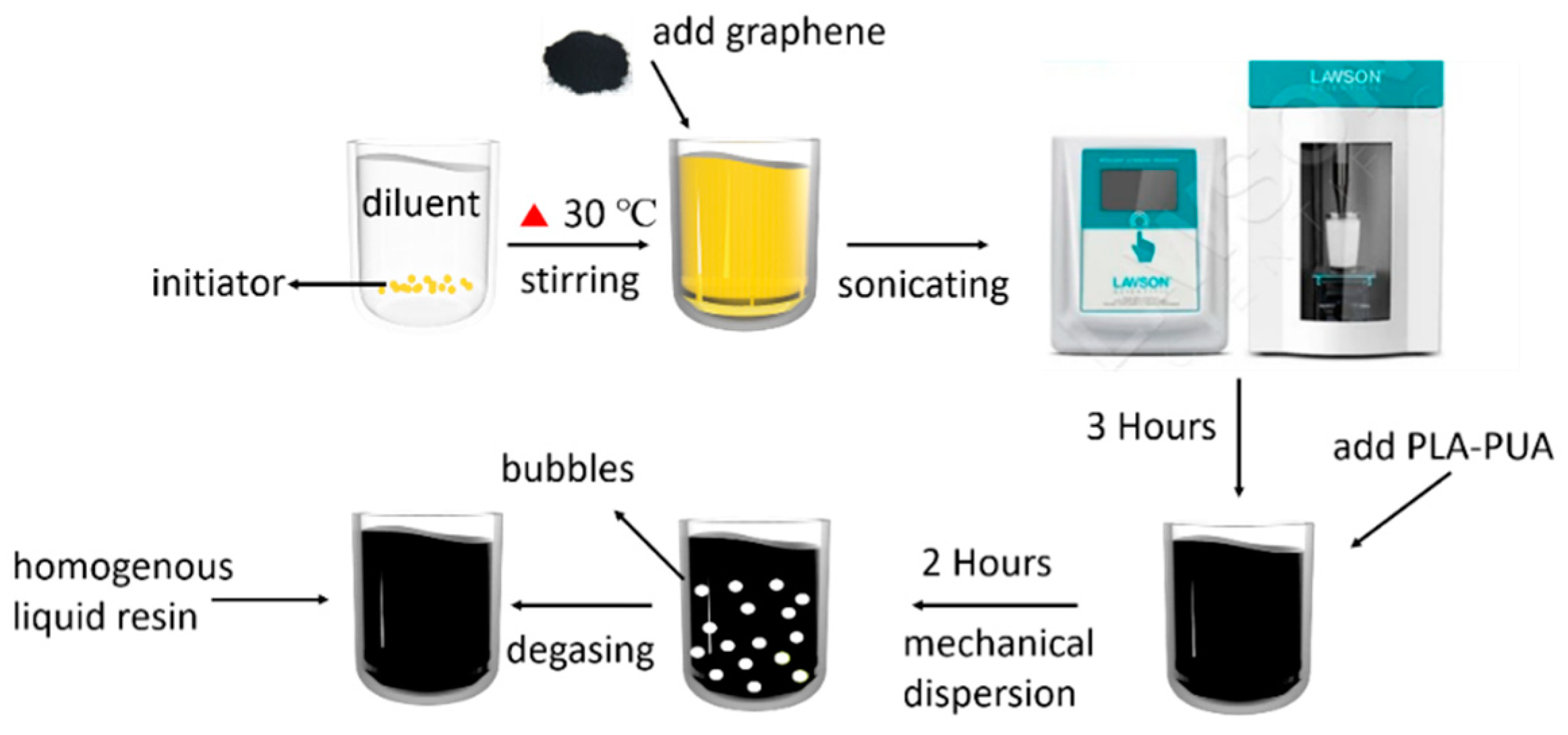
2.2. Preparation of UV-Curable Resin

The matrix chosen for this work was a neat resin consisting of PLA–PUA, TEGDMA, and Irgacure 819 with the ratio of 58:39:3 in weight. PLA–PUA was chosen as the oligomer owing to its good biodegradability, and TEGDMA was used as a reactive diluent. Irgacure 819 was used as an initiator due to its high photoinitiation effect. Detailed information about the used raw materials as well as the procedure to form the neat resin can be found in our previous work [25]. To produce a graphene-reinforced nanocomposite, Irgacure 819 powder was firstly mixed with TEGDMA and stirred at 30 °C for 20 min. Then, a measured amount of graphene powder (0.5 wt.%) was dispersed in the above diluent and treated with ultrasonication for 3 h using an ultrasonic probe (LAWSON DH92-IIN, Ningbo, China, 650 W, 20 kHz, amplitude at 60%, power on/off: 1 s/1 s). The resulting solution was subsequently mixed with PLA–PUA for another 2 h under magnetic stirring before the final degassing step, as illustrated in Figure 1.

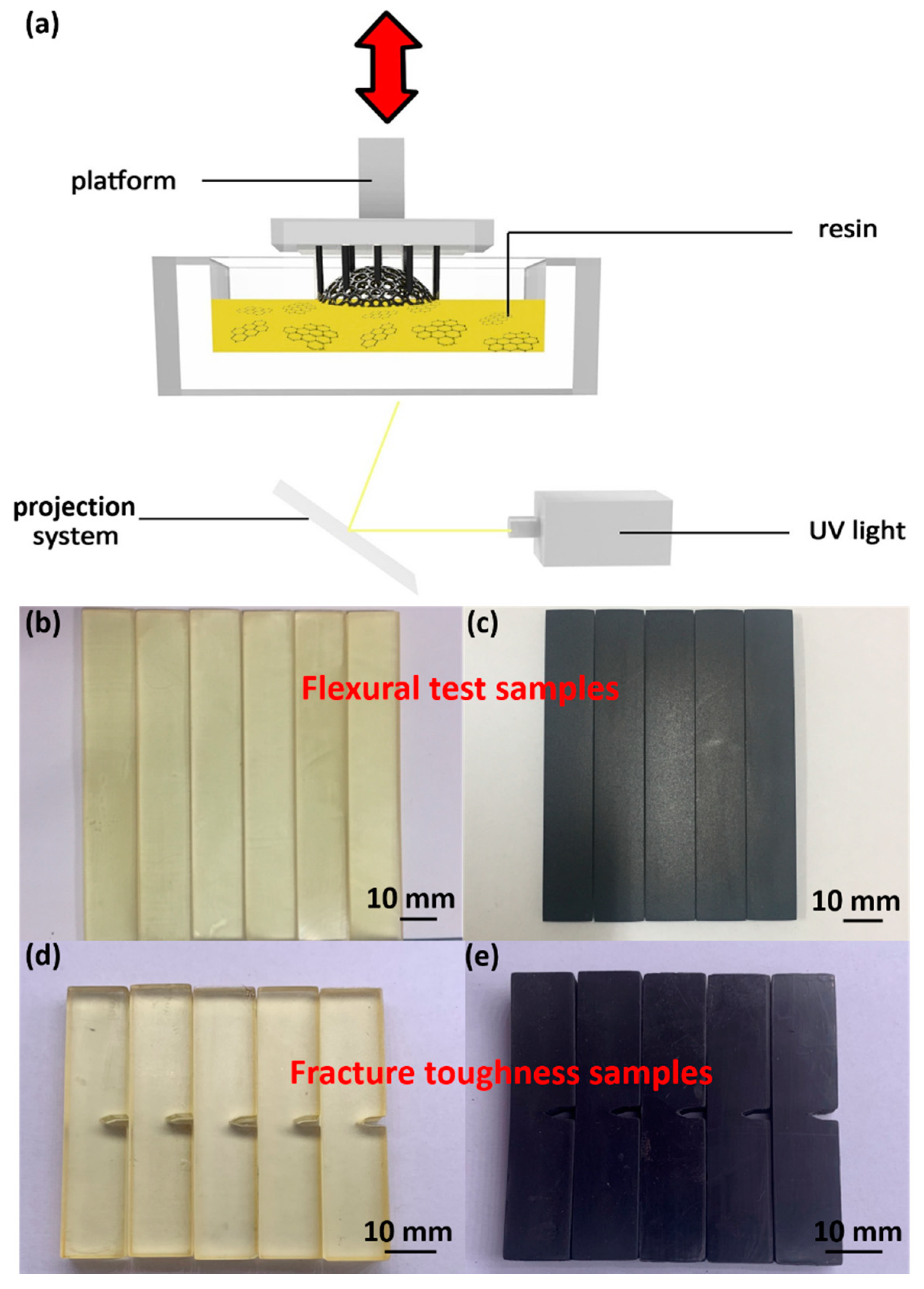
2.3. Fabrication of UV-Cured Resin by DLP

The flexural and fracture toughness test specimens were fabricated to a net shape directly by a 405-nm DLP 3D printer (Photon, ANYCUBIC, Shenzhen, China), as illustrated in Figure 2a. The XY resolution and the Z-axis accuracy of the DLP 3D printer could reach 47 and 1.25 µm, respectively. The size of the building volume of the DLP 3D printer was 115 × 65 × 155 mm3, with the print speed set to 0.020 m h−1. Three-dimensional models were built by Rhinoceros software (version 5.0, Robert McNeel Ltd., USA) with a generated .STL file. ANYCUBIC Photon Slicer software (ANYCUBIC Ltd., Shenzhen, China) was used to slice the .STL file as well as set the printing parameters.

2.4. Characterizations

2.4.1. Morphology

Scanning electron microscopy (SEM, Hitachi SU8010, Hitachi High-Technologies Co., Ltd., Tokyo, Japan) tests were conducted to examine the morphology of both the received graphene nanofillers and the fabricated specimens, especially for the specimens with the addition of graphene nanoplatelets. The graphene fillers were dispersed in order to examine their morphological features as well as dimensions. The fracture surface of the tested KIC specimens were gold coated and examined, with an acceleration voltage of 5 kV at various magnifications. An optical microscope (OM, Leica M205 A, Leica Microsystems, Wetzlar, Germany) was also used to observe the surface appearance of the fracture surfaces after the fracture toughness test.
X-ray diffraction (XRD, D8-FOCUS, Bruker AXS GmbH, Karlsruhe, Germany) was used to characterize the thickness of the graphene flakes. The X-ray texture scans were obtained between 2θ = 5° − 90° at a scanning rate of 1°/min. The average out-of-plane crystallite thickness of the GNPs (t) was estimated using the full width at half-maximum (FWHM) of the (002) peak by Scherrer’s equation. The coefficient K was taken to be 0.89 according to Raza et al. [26]. For more details, please refer to our previous work [27,28].
Raman spectra (XploRA plus, HORIBA, Fukuoka, Japan) of the graphene flakes were characterized with an excitation wavelength of 532 nm.

2.4.2. Viscosity

A viscometer (LV DV-II+Pro, Brookfield, Middleboro, MA, USA) was used to examine the viscosity of both the liquid reference resin and the graphene-reinforced resin, with the temperature and rotation speed ranging from 20 to 35 °C and 6 to 60 rpm, respectively.

2.4.3. Cure Depth

The cure depth of the resin was tested by measuring the thickness of a UV-cured resin film after exposing the liquid resin in a 405-nm UV curing machine (Cure3D, MAKEX, Ningbo, China) for 5 min. The value of the cure depth was based on the average of three repetitions.

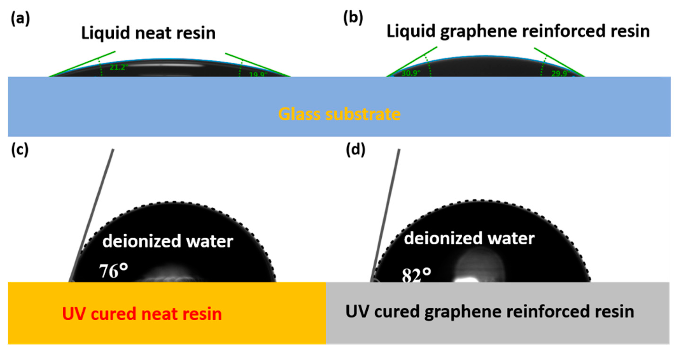
2.4.4. Surface Characterization

The contact angle was measured by a drop shape analyzer (DSA, JC2000C1, Shanghai Zhongchen Digital Technic Apparatus Co., Ltd., Shanghai, China) using the sessile drop method. A drop of water or liquid resin was squeezed from a syringe on the surface of UV-cured resin or a glass substrate vertically. The image of the contact angle was recorded after 5 s. A tension meter (JK99B, Shanghai Zhongchen Digital Technic Apparatus Co., Ltd., Shanghai, China) was used to test the surface tension of the liquid resin.

2.4.5. FTIR

Fourier transform infrared spectroscopy (FTIR, Nicolet iS50, Thermo Fisher Scientific, Waltham, MA, America) was used to examine the chemical structure of the UV-cured 0.5 wt.% graphene-based nanocomposites.

2.4.6. Thermomechanical Analysis

Dynamic mechanical analysis (DMA) was carried out using a dynamic mechanical analyzer (DMA/SDTA861e, Mettler Toledo, Zurich, Switzerland) under shear mode. Cylindrical specimens (d = 10 mm, thickness: ca. 1 mm) were heated from 30 to 300 °C at 5 °C∙min−1 with an amplitude of 10 µm at a frequency of 1 Hz. Values of storage modulus (E’) and tan delta (tan δ) were recorded.
A thermalgravimetric analyzer (TG, Model STA449F3, NETZSCH, Selb, Germany) was employed to characterize the thermal stability of the composites as well as the amount of filler, with the temperature profile of ranging from 30 to 500 °C at 5 °C∙min−1 under nitrogen atmosphere.

2.4.7. Mechanical Properties

A 10-kN microcomputer control electronic universal testing machine (Instron, CMT4104, Shanghai, China) was used to test mechanical properties. According to the ASTM-D 790 standard, the flexural test samples were fabricated by the DLP 3D printer with dimensions of 3.2 × 12.7 × 70 mm3 (Figure 2b,c). The support-span-to-depth ratio was 16:1, while the strain rate of the crosshead, in accordance with ASTM-D 790, was set as 0.01 mm/mm/min. The ASTM-D 5045 standard was implemented to evaluate the fracture toughness (KIC) in three-point end notch bending (3P-ENB) test mode. The dimensions (Figure 2d,e) of the 3D-printed samples were 54 (length) × 12 (width, W) × 6 mm (thickness, B). The support length of the three-point bending test was 48 mm with a crosshead speed of 10 mm∙min−1. The length of the crack was 6 mm, and sharp notch tips with angles of 30° and 45° were designed to promote early crack initiation without a further fresh razor blade notch. A schematic of the specimen can be found in the Supplementary Materials, Figure S1. Every surface of the specimens was carefully polished to remove any surface roughness with different grades of abrasive paper (from 1000 to 5000 grit). A minimum of five specimens were tested for the average values of both neat resin and graphene-reinforced nanocomposite samples. KIC (plane-strain fracture toughness) was calculated according to Equations (1) and (2):
f ( a W ) = 6 ( a W ) 1 2 { [ 1.99 a W ( 1 a W ) ( 2.15 3.93 a W + 2.7 ( a W ) 2 ] ( 1 + 2 a W ) ( 1 a W ) 3 2 }
K IC = P max B W 1 2 f ( x )   And   0.45   <   x   <   0.55
where a is the crack length, W is the width of the specimen, Pmax is the maximum load of the load-displacement curve, and B is the thickness of the specimen. The measurement units of the variables Pmax, B, W, and a can be retrieved from the standard ASTM-D 5045.

3. Results and Discussion

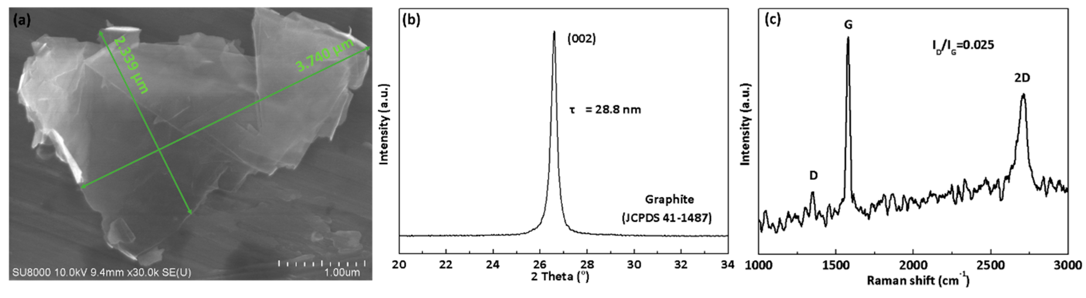
3.1. Morphological Analysis of As-Received Graphene Fillers

The morphology of the as-received graphene flakes used in this study was examined by SEM, as shown in Figure 3a, indicating lateral dimensions in the range of a few microns. The graphene flakes after liquid-phase probe sonication were obtained without obvious aggregation, which is believed to be crucial for later DLP processing. The XRD pattern of the as-received graphene flakes is presented in Figure 3b. The interplanar spacing of the (002) peak at 26.6° was 3.35 nm, and the corresponding mean thickness of the as-received graphene fillers obtained from Scherrer’s equation was about 28.8 nm. The lateral dimensions from the SEM images of the GNPs were in the range of 3–9 μm, in good agreement with the suppliers’ information with an aspect ratio (the ratio between the graphene platelet length and thickness, LSEM/TXRD) of 100–300. Signature D and G bands of graphene flakes were observed in 1039 and 1581 cm−1 from Raman spectroscopy (Figure 3c), confirming low defect content in the graphitic structure.

3.2. Viscosity and Printability of Current Nanocomposite Resin

For DLP or SLA 3D printing technologies, the viscosity of the resin is an extremely important parameter, affecting the printing feasibility and quality of the parts, and a relatively low viscosity (from 0.25 to 1 Pa·s) is required for DLP or SLA 3D printing [29]. Too high viscosity of the resin may lead to some deformation or failures of the printed components. Although the amount of graphene fillers added in this work was rather limited (0.5 wt.%), the viscosity was characterized first to ensure good capability for the use of 3D printing.
As expected, the addition of 0.5 wt.% graphene fillers led to an increase in liquid resin viscosity, from 860 to 1332 mPa·s at 20 °C (Table 1). With increased temperature, the graphene-modified resin viscosity decreased rapidly, with only 362 mPa·s at 35 °C, which was already close to the neat resin (200 mPa·s). For the printing temperature of 25 °C, the viscosity of liquid resin without or with graphene was approximately 504 and 742 mPa·s, respectively, which are both suitable for DLP processing.
With the addition of graphene fillers in liquid resins, the surface tension of the resin will also be affected, which may affect the printing process. The contact angles of both neat resin and 0.5 wt.% graphene-reinforced resin on a glass substrate were measured, showing an increased value from around 20° to 30° (Figure 4a,b). The yield surface tensions of the liquid neat resin and 0.5 wt.% graphene-reinforced resin were 37 and 41 mN m−1, respectively. After UV curing, the water contact angles of solid neat resin and 0.5 wt.% graphene-reinforced resin were 76° and 82° (Figure 4c,d), showing an increased hydrophobicity of the materials with the addition of graphene fillers.
The cure depth value of the 0.5 wt.% graphene-reinforced resin showed a sharp decrease compared with the neat resin without graphene. This observation indicates that the printability of the resin will decrease with the increasing amount of graphene, which is believed to be due to the existence of graphene interfering with the photocuring process of the resin [30,31].

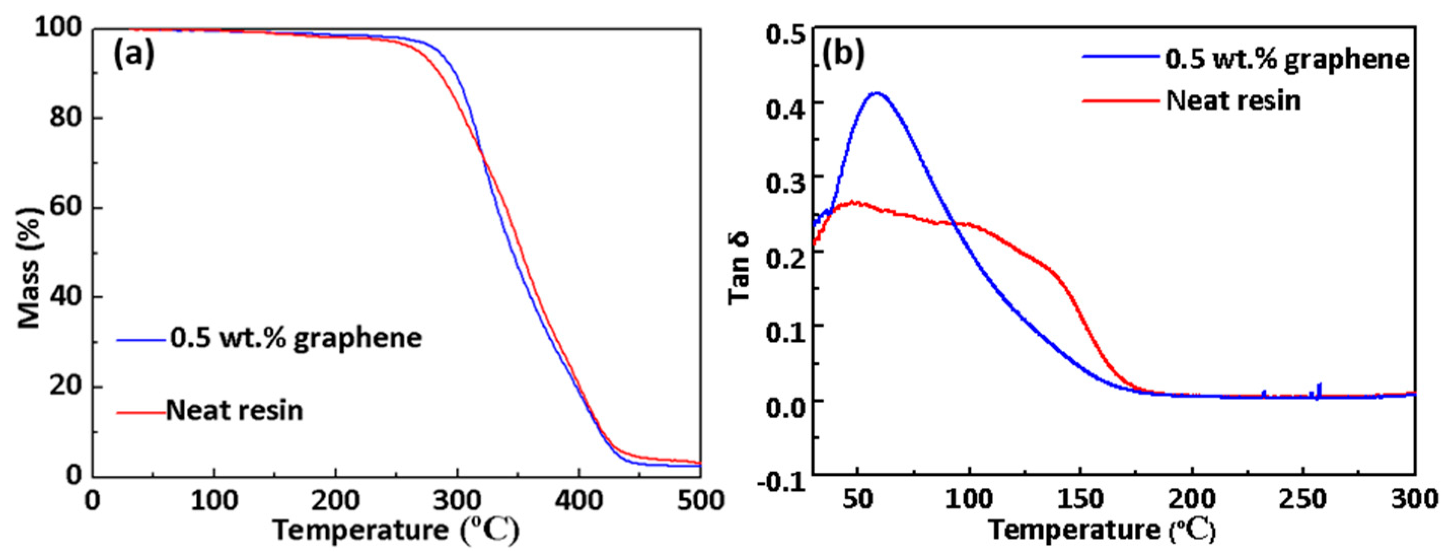
3.3. Thermal Characterization

TGA results (Figure 5a) were analyzed to examine the thermal stability of UV-cured resin. The UV-cured resin was thermally stable below 200 °C, while a rapid weight loss was observed at 250 °C, corresponding to the fragmentation of macromolecules, disproportionation, and gasification processes [32]. The initial degradation temperature of UV-cured resin was evaluated by the temperature of 5% mass loss (T5%). The degradation temperature of the graphene-reinforced nanocomposite was higher than neat resin (T5% increased from 268 °C to 284 °C), showing that the addition of graphene could enhance the thermal stability of graphene-modified resin. The weights of both the neat resin and the graphene-reinforced nanocomposite were constant above 430 °C, indicating the completion of the decomposition. The glass transition temperature (Tg) determined by the maximum peak of tan δ from the DMA result (Figure 5b) also remained at the same level as the reference after introducing graphene nanofillers, indicating no obvious changes in crosslink density for cured resin with the addition of graphene nanofillers. In general, the current resin formulation has a suitable viscosity with good printability for DLP processing. The chemical structure of the graphene-reinforced nanocomposite was also confirmed from FTIR spectra. FTIR of 0.5 wt.% graphene-reinforced nanocomposites was performed (Figure S2) to characterize the chemical bonding of graphene and PLA–PUA, with no specific signs of chemical reaction induced by the addition of graphene.

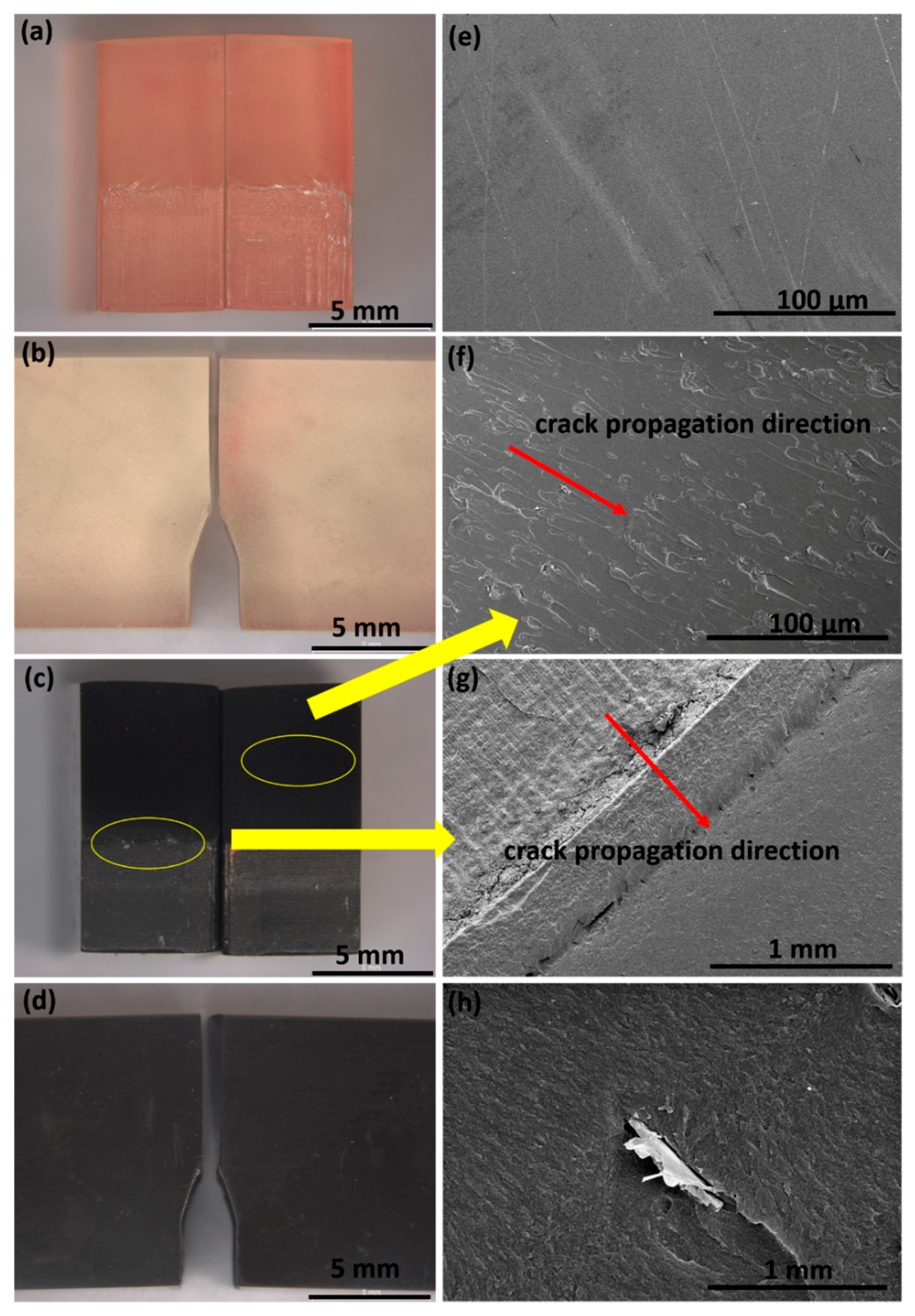
3.4. Mechanical Properties

Figure 6 shows the mechanical characterization results of DLP-fabricated net-shaped specimens for both neat resin and graphene-reinforced nanocomposites. With the addition of 0.5 wt.% graphene, the flexural modulus of the cured specimen increased from 2.68 GPa of neat resin to 3.06 GPa (Figure 6a), showing a reasonable improvement (14%) without any obvious sacrifice in flexural strength (4% increment from reference was obtained). The modulus of the 3D-printed 0.5 wt.% graphene nanocomposites was compared to theoretical predictions using the Halpin–Tsai semiempirical micromechanical model (see Supplementary Information). Ec/Em (Ec and Em are the modulus of the final composite and neat matrix, respectively) values plotted as a function of the GNP aspect ratio (AR = 200) followed a sigmoidal curve, as predicted by the Halpin–Tsai model (Figure S3). The experimental data could be best fitted assuming a 3D random orientation of platelets with a back-calculated elastic modulus around 780 GPa. Such a GNP modulus value is in agreement with literature values [27,33,34] and is believed to be due to the good dispersion from the DLP process as well. For mechanical and thermal properties of nanocomposites, it is well acknowledged that an optimized nanofiller dispersion is favored, while for electrical properties, a slightly agglomerated nanofiller dispersion is preferred to build up the percolated network. Clearly, with the current rapid curing process of the DLP method, initial graphene dispersion within liquid resin can be retained after curing, leading to the well-dispersed network more favored for mechanical and thermal reinforcements. Kernin et al. [24] obtained a 12% increase in flexural modulus of reduced GO (rGO)/epoxy nanocomposites at 0.2 wt.% loading, followed by a decreasing trend with higher loading of fillers due to the potential agglomeration from traditional-length curing processes. Wang et al. [30] recommended a graphene content less than 5 wt.% to maintain the appearance and mechanical strength of the printed object. It is worth noting that the presence of graphene nanofillers could block UV light during the DLP process and thus interfere with the photocuring process of the resin, affecting the mechanical properties of the resulting specimens. However, it is believed that with the current limited amount of graphene nanofillers with relatively homogeneous dispersion, the crosslink density was not obviously affected, as confirmed earlier from the measured Tg.
Since the net-shaped specimen was successfully fabricated without subsequent cutting and complex sample preparation steps, it was important and necessary to examine the effect of the initial crack angle on the fracture toughness tests and obtained results. Two angles for the sharp notch tips, 30° and 45°, were employed and printed, with the images presented in Figure 6c for both failed and successful fracture toughness test specimens on the neat resin. It was found that with the notch tip with the angle of 45°, the possibility of a failed test was significantly increased compared with the specimen with a 30° angle, regardless of the relatively high but potentially artificial values of KIC obtained. This finding is in consistent with a recent report in the literature that a 30° angle could promote early crack initiation [35], facilitating the KIC tests. Although there are still very few failed KIC tests with 30° (Figure S4), the resulting fracture surface was much smoother than the crack with the angle of 45°, with a higher success rate. Therefore, all the specimens were designed and printed with a crack notch angle of 30° to ensure the validity of the KIC test, with a minimum of five specimens evaluated.
The fracture toughness (KIC) values of neat and graphene-reinforced specimens are presented in Figure 6b. Higher values of KIC indicated that a higher amount of energy was required to fracture the specimen. With 0.5 wt.% graphene nanofillers, a 28% increase from the neat reference was obtained, which is believed to be due to the crack bridging and crack deflection of nanofillers with a great increase in fracture surface areas compared with the brittle reference. Numerous reported studies have indicated that graphene-based nanofillers reinforcing a polymer matrix have shown a great enhancement in the performance of fracture toughness. Alexopoulos et al. [36] obtained a 12% increase in fracture toughness with 1 wt.% GNPs, illustrating that low nanofiller content (<1.0 wt.%) reinforced polymer composites show a great enhancement in fracture toughness, while filler concentrations exceeding a certain point (>5.0 wt.%) might cause a decrease of the mechanical properties due to agglomerates of nanofillers. Tang et al. [37] found that the mechanical performance of graphene/epoxy composites is closely related to the dispersion of the graphene filler. Poorly and highly dispersed 0.2 wt.% rGO/epoxy composites showed a 24% and 52% improvement in KIC, respectively. Chatterjee et al. [38] illustrated that 2 wt.% GNP with a lateral dimension of 25 µm exhibited the highest improvement of 82% over neat epoxy. Qiu et al. [39] obtained an increase of 41% in KIC with the addition of 0.54 vol % exfoliated graphene in comparison with neat epoxy resin. Herrera-Ramírez et al. [40] confirmed that the highest KIC value (~25% improvement over neat resin) was obtained for 1 wt.% graphene/polypropylene nanocomposites. While limited research has been reported related to fracture toughness tests for nanofiller-reinforced polymers fabricated via 3D printing method, Young et al. [41] reported a fused filament fabrication (FFF) method to fabricate KIC specimens using short carbon-fiber-reinforced acrylonitrile butadiene styrene (ABS) filaments. However, the FFF process was found to reduce the KIC of ABS and chopped carbon-fiber-reinforced ABS. Rapid cool-down of the material and the existence of voids inside the specimens may serve to reduce fracture toughness. By isothermally heating the ABS KIC specimens produced via the FFF method, the KIC value dramatically increased compared with that without thermal annealing [42]. SLA is a more accurate 3D printing method compared with FFF and can produce finely detailed objects and provide better performance. Li et al. [43] manufactured stereolithography resin nanocomposites with modified polyhedral oligomeric silsesquioxane (m-POSS) nanoparticles. The tensile and flexible strengths of 5 wt.% mPOSS nanocomposites were improved by 36.2% and 40%, respectively, compared with neat resin, while the fracture toughness exhibited a slightly reducing trend.
Optical microscopy images of successfully tested fracture toughness specimens are presented in Figure 7a–d, showing the fracture surface as well as the lateral view of the fractured neat resin and 0.5 wt.% graphene-reinforced nanocomposites. Clearly, with a 30° notch angle, clear crack initiation and propagation can be observed (Figure 7a–d), with the crack propagating along the perpendicular direction of the sample length. In contrast, the crack in 45° notch angle specimens propagated with a clear deviation, resulting in the inaccurate calculation of actual crack length and subsequently affecting the yielded KIC values (Figure S5). These observations are in good agreement with the calculated KIC values discussed in the previous section. The fracture surface of successfully tested specimens were further examined by SEM to investigate the toughening mechanism of the graphene-reinforced nanocomposite with improved KIC values (Figure 7e–h). Figure 7e reveals that the fracture surface of the neat resin was smooth and mirror-like. In contrast, after the introduction of 0.5 wt.% graphene, the fracture surface of the nanocomposite (Figure 7f) was much rougher than that of the neat resin, indicating higher energy dissipation during crack propagation and resulting in high fracture toughness [44]. Figure 7f shows a relatively homogeneous distribution of graphene sheets within the specimen, confirming the effectiveness of the initial dispersion and rapid curing process of the DLP method. The insert line indicates the crack propagation direction (Figure 7f). Traces of graphene sheets pulled out during the fracture can be observed in Figure 7h, which contributed to the improved fracture toughness with increased surface areas.
With increased fracture toughness value and, hence, a higher resistance to brittle failure without sacrificing flexural strength, currently developed graphene-reinforced resin can be used for various applications such as preparing porous bone structures and scaffolds via DLP. A jawbone with a square architecture (the shape of the scaffold pores) was successfully fabricated (Figure 8a,b), demonstrating the feasibility of current resin for net-shaped fabrication with complex structures. To further examine the printability of graphene-reinforced resins, a 3D scaffold architecture was printed using DLP, as shown in Figure 8c,d. Several studies have focused on 3D-printed scaffold architectures, with varied modulus values of materials ranging from a few MPa to GPa level [45,46,47,48]. For instance, the flexural strength and modulus of a poly(D,L-lactide)-based scaffold were 94 MPa and 2.9 GPa, respectively [48]. The mechanical properties of the current PLA–PUA/TEGDMA material are within the same range as previously reported values, with slightly higher values than some of those found in previous works. With the aid of DLP, the bone structure and scaffold can be personalized and tailored for individual clinic applications, which can provide great savings in terms of both cost and time for medical personnel as well as patients [49,50]. The potential electrical and microwave absorbing properties of graphene and other nanofillers also open new possibilities for 3D-printed polymer/graphene composites to be implemented in other fields such as electromagnetic interference shielding [51].

4. Conclusions

A solvent-free method to fabricate graphene-reinforced nanocomposites via DLP was successfully developed without sacrificing the printability of modified resin. The resin viscosity and printability with the addition of nanofillers were characterized and analyzed, while the thermomechanical properties of current nanocomposites were also examined, confirming no obvious effect on the printability or the photocuring process with the addition of graphene nanofillers. The rapid curing nature of the current method enabled relatively homogeneous nanofiller dispersion without the obvious agglomerates which may occur from the traditionally lengthy curing process of resins. As a result, the mechanical properties of graphene-reinforced nanocomposites were substantially improved with only 0.5 wt.%, showing a 14% increment in flexural modulus and a 28% improvement in fracture toughness.
To explore and utilize the capability of fabricating net-shaped specimens with DLP, the feasibility of printing fracture toughness specimens with different notch tip angles without subsequent complex sample preparation steps was examined, with specimens successfully tested based on the three-point end notch bending method. With a 30° notch angle, early crack initiation with clean and straight crack propagation was observed, indicating the effectiveness of using the current method to perform rapid trials on new formulations with improved fracture toughness.
With the developed graphene-reinforced resins, 3D complex structures including a jawbone with a square architecture as well as gyroid scaffold for bone tissue engineering applications were successfully fabricated via DLP, showing the great potential of current UV-curable nanocomposite resin systems for various applications in fields such as bioengineering.

Supplementary Materials

The following are available online at https://0-www-mdpi-com.brum.beds.ac.uk/2311-5629/5/2/25/s1, Figure S1: Schematic of the KIC specimen, Figure S2: FTIR spectra of 0.5 wt.% graphene-reinforced nanocomposites, Figure S3: Halpin-Tsai models with Mori–Tanaka modified shape factor of composite modulus ratio Ec/Em as a function of filler aspect ratio together with experimental data of 0.03 Vol% graphene nanocomposites. Model predictions assumed for platelet moduli of 780 GPa with a 2D planar or 3D random orientation, Figure S4: The KIC value and optical images of failed fracture toughness test specimens for the neat resin with 30° sharp notch tips, Figure S5: Optical microscopy images of fracture surface and fractured lateral view of graphene/resin composites after a failed fracture toughness test (a,b) the neat resin specimens; (c,d) 0.5 wt.% nanocomposites specimens; SEM images of the fracture surfaces of 0.5 wt.% nanocomposites specimens after a failed fracture toughness test (e) magnification of the circled domain in (c) and (f) magnification of the circled domain in (e).

Author Contributions

For research articles with several authors, a short paragraph specifying their individual contributions must be provided. conceptualization, Y.L.; methodology, Z.F. and Y.L.; software, D.T. and W.X.; validation, Z.F., C.X. and D.T.; formal analysis, Z.F., Y.L. and H.Z.; investigation, Z.F.; resources, Y.L.; data curation, Z.F., C.X. and D.T.; writing—original draft preparation, Z.F. and H.Z.; writing—review and editing, H.Z.; supervision, Y.L. and H.Z.; project administration, Y.L.; funding acquisition, Y.L.

Funding

The project was kindly supported by the fundamental research funds for the central universities, China University of Geosciences (Wuhan) (no. cug170677).

Acknowledgments

The authors gratefully acknowledge Esun Co., Ltd. for providing the polylactic acid–polyurethane oligomer.

Conflicts of Interest

The authors declare that there is no conflict of interests regarding the publication of this paper.

References

  1. Ma, H.; Luo, J.; Sun, Z.; Xia, L.; Shi, M.; Liu, M.; Chang, J.; Wu, C. 3D printing of biomaterials with mussel-inspired nanostructures for tumor therapy and tissue regeneration. Biomaterials 2016, 111, 138–148. [Google Scholar] [CrossRef] [PubMed]
  2. Tang, D.; Hao, L.; Li, Y.; Xiong, W.; Sun, T.; Yan, X. Investigation of wax-based barite slurry and deposition for 3D printing landslide model. Compos. Part A Appl. Sci. Manuf. 2018, 108, 99–106. [Google Scholar] [CrossRef]
  3. Rengier, F.; Mehndiratta, A.; von Tengg-Kobligk, H.; Zechmann, C.M.; Unterhinninghofen, R.; Kauczor, H.U.; Giesel, F.L. 3D printing based on imaging data: Review of medical applications. Int. J. Comput. Assist. Radiol. Surg. 2010, 5, 335–341. [Google Scholar] [CrossRef]
  4. Postiglione, G.; Natale, G.; Griffini, G.; Levi, M.; Turri, S. Conductive 3D microstructures by direct 3D printing of polymer/carbon nanotube nanocomposites via liquid deposition modeling. Compos. Part A Appl. Sci. Manuf. 2015, 76, 110–114. [Google Scholar] [CrossRef]
  5. Leigh, S.J.; Purssell, C.P.; Bowen, J.; Hutchins, D.A.; Covington, J.A.; Billson, D.R. A miniature flow sensor fabricated by micro-stereolithography employing a magnetite/acrylic nanocomposite resin. Sens. Actuators A Phys. 2011, 168, 66–71. [Google Scholar] [CrossRef]
  6. Xiong, W.; Hao, L.; Li, Y.; Tang, D.; Cui, Q.; Feng, Z.; Yan, C. Effect of selective laser melting parameters on morphology, microstructure, densification and mechanical properties of supersaturated silver alloy. Mater. Des. 2019, 170, 107697. [Google Scholar] [CrossRef]
  7. Fantino, E.; Chiappone, A.; Calignano, F.; Fontana, M.; Pirri, F.; Roppolo, I. In Situ Thermal Generation of Silver Nanoparticles in 3D Printed Polymeric Structures. Materials 2016, 9, 589. [Google Scholar] [CrossRef] [PubMed]
  8. Mu, Q.; Wang, L.; Dunn, C.K.; Kuang, X.; Duan, F.; Zhang, Z.; Qi, H.J.; Wang, T. Digital light processing 3D printing of conductive complex structures. Addit. Manuf. 2017, 18, 74–83. [Google Scholar] [CrossRef]
  9. Liu, Y.; Zhang, H.; Porwal, H.; Tu, W.; Evans, J.; Newton, M.; Busfield, J.J.C.; Peijs, T.; Bilotti, E. Universal Control on Pyroresistive Behavior of Flexible Self-Regulating Heating Devices. Adv. Funct. Mater. 2017, 27, 1702253. [Google Scholar] [CrossRef]
  10. Liu, Y.; Zhang, H.; Porwal, H.; Tu, W.; Wan, K.; Evans, J.; Newton, M.; Busfield, J.J.C.; Peijs, T.; Bilotti, E. Tailored pyroresistive performance and flexibility by introducing a secondary thermoplastic elastomeric phase into graphene nanoplatelet (GNP) filled polymer composites for self-regulating heating devices. J. Mater. Chem. C 2018, 6, 2760–2768. [Google Scholar] [CrossRef]
  11. Kang, Y.; Wang, C.; Qiao, Y.; Gu, J.; Zhang, H.; Peijs, T.; Kong, J.; Zhang, G.; Shi, X. Tissue-Engineered Trachea Consisting of Electrospun Patterned sc-PLA/GO-g-IL Fibrous Membranes with Antibacterial Property and 3D-Printed Skeletons with Elasticity. Biomacromolecules 2019, 20, 1765–1776. [Google Scholar] [CrossRef]
  12. Shuai, C.; Feng, P.; Gao, C.; Shuai, X.; Xiao, T.; Peng, S. Graphene oxide reinforced poly(vinyl alcohol): Nanocomposite scaffolds for tissue engineering applications. RSC Adv. 2015, 5, 25416–25423. [Google Scholar] [CrossRef]
  13. Mohan, V.B.; Krebs, B.J.; Bhattacharyya, D. Development of novel highly conductive 3D printable hybrid polymer-graphene composites. Mater. Today Commun. 2018, 17, 554–561. [Google Scholar] [CrossRef]
  14. Manapat, J.Z.; Mangadlao, J.D.; Tiu, B.D.; Tritchler, G.C.; Advincula, R.C. High-Strength Stereolithographic 3D Printed Nanocomposites: Graphene Oxide Metastability. ACS Appl. Mater. Interfaces 2017, 9, 10085–10093. [Google Scholar] [CrossRef]
  15. Weng, Z.; Zhou, Y.; Lin, W.; Senthil, T.; Wu, L. Structure-property relationship of nano enhanced stereolithography resin for desktop SLA 3D printer. Compos. Part A Appl. Sci. Manuf. 2016, 88, 234–242. [Google Scholar] [CrossRef]
  16. Tiller, B.; Reid, A.; Zhu, B.; Guerreiro, J.; Domingo-Roca, R.; Curt Jackson, J.; Windmill, J.F.C. Piezoelectric microphone via a digital light processing 3D printing process. Mater. Des. 2019, 165, 107593. [Google Scholar] [CrossRef]
  17. Na, K.; Shin, S.; Lee, H.; Shin, D.; Baek, J.; Kwak, H.; Park, M.; Shin, J.; Hyun, J. Effect of solution viscosity on retardation of cell sedimentation in DLP 3D printing of gelatin methacrylate/silk fibroin bioink. J. Ind. Eng. Chem. 2018, 61, 340–347. [Google Scholar] [CrossRef]
  18. Fantino, E.; Chiappone, A.; Roppolo, I.; Manfredi, D.; Bongiovanni, R.; Pirri, C.F.; Calignano, F. 3D Printing of Conductive Complex Structures with In Situ Generation of Silver Nanoparticles. Adv. Mater. 2016, 28, 3712–3717. [Google Scholar] [CrossRef]
  19. Gonzalez, G.; Chiappone, A.; Roppolo, I.; Fantino, E.; Bertana, V.; Perrucci, F.; Scaltrito, L.; Pirri, F.; Sangermano, M. Development of 3D printable formulations containing CNT with enhanced electrical properties. Polymer 2017, 109, 246–253. [Google Scholar] [CrossRef]
  20. Han, Y.; Wang, F.; Wang, H.; Jiao, X.; Chen, D. High-strength boehmite-acrylate composites for 3D printing: Reinforced filler-matrix interactions. Compos. Sci. Technol. 2018, 154, 104–109. [Google Scholar] [CrossRef]
  21. Chiappone, A.; Roppolo, I.; Naretto, E.; Fantino, E.; Calignano, F.; Sangermano, M.; Pirri, F. Study of graphene oxide-based 3D printable composites: Effect of the in situ reduction. Compos. Part B Eng. 2017, 124, 9–15. [Google Scholar] [CrossRef]
  22. Han, H.; Cho, S. Fabrication of Conducting Polyacrylate Resin Solution with Polyaniline Nanofiber and Graphene for Conductive 3D Printing Application. Polymers 2018, 10, 1003. [Google Scholar] [CrossRef]
  23. Zhang, H.; Bilotti, E.; Tu, W.; Lew, C.Y.; Peijs, T. Static and dynamic percolation of phenoxy/carbon nanotube nanocomposites. Eur. Polym. J. 2015, 68, 128–138. [Google Scholar] [CrossRef]
  24. Kernin, A.; Wan, K.; Liu, Y.; Shi, X.; Kong, J.; Bilotti, E.; Peijs, T.; Zhang, H. The effect of graphene network formation on the electrical, mechanical, and multifunctional properties of graphene/epoxy nanocomposites. Compos. Sci. Technol. 2019, 169, 224–231. [Google Scholar] [CrossRef]
  25. Feng, Z.; Li, Y.; Hao, L.; Yang, Y.; Tang, T.; Tang, D.; Xiong, W. Graphene-Reinforced Biodegradable Resin Composites for Stereolithographic 3D Printing of Bone Structure Scaffolds. J. Nanomater. 2019, 2019, 1–13. [Google Scholar] [CrossRef]
  26. Raza, M.A.; Westwood, A.; Brown, A.; Hondow, N.; Stirling, C. Characterisation of graphite nanoplatelets and the physical properties of graphite nanoplatelet/silicone composites for thermal interface applications. Carbon 2011, 49, 4269–4279. [Google Scholar] [CrossRef]
  27. Li, Y.; Zhang, H.; Porwal, H.; Huang, Z.; Bilotti, E.; Peijs, T. Mechanical, electrical and thermal properties of in-situ exfoliated graphene/epoxy nanocomposites. Compos. Part A Appl. Sci. Manuf. 2017, 95, 229–236. [Google Scholar] [CrossRef]
  28. Li, Y.; Zhang, H.; Crespo, M.; Porwal, H.; Picot, O.; Santagiuliana, G.; Huang, Z.; Barbieri, E.; Pugno, N.M.; Peijs, T.; et al. In Situ Exfoliation of Graphene in Epoxy Resins: A Facile Strategy to Efficient and Large Scale Graphene Nanocomposites. ACS Appl. Mater. Interfaces 2016, 8, 24112–24122. [Google Scholar] [CrossRef]
  29. Huang, B.W.; Cheng, G.L.; Deng, C.; Zou, H.H. Investigation on some Properties of RenshapeTM SL7545 Type Photosensitive Resin and its Application for Stereolithography Material. Appl. Mech. Mater. 2012, 252, 220–223. [Google Scholar] [CrossRef]
  30. Wang, D.; Huang, X.; Li, J.; He, B.; Liu, Q.; Hu, L.; Jiang, G. 3D printing of graphene-doped target for “matrix-free” laser desorption/ionization mass spectrometry. Chem. Commun. 2018, 54, 2723–2726. [Google Scholar] [CrossRef]
  31. Lim, S.M.; Shin, B.S.; Kim, K. Characterization of Products Using Additive Manufacturing with Graphene/Photopolymer-Resin Nano-Fluid. J. Nanosci. Nanotechnol. 2017, 17, 5492–5495. [Google Scholar] [CrossRef]
  32. Li, J.; Cui, Y.; Qin, K.; Yu, J.; Guo, C.; Yang, J.; Zhang, C.; Jiang, D.; Wang, X. Synthesis and properties of a low-viscosity UV-curable oligomer for three-dimensional printing. Polym. Bull. 2015, 73, 571–585. [Google Scholar] [CrossRef]
  33. Frank, I.W.; Tanenbaum, D.M.; Zande, A.M.V.D.; Mceuen, P.L. Mechanical properties of suspended graphene sheets. J. Vac. Sci. Technol. B Microelectron. Nanom. Struct. 2007, 25, 2558–2561. [Google Scholar] [CrossRef]
  34. Zhang, Y.; Pan, C. Measurements of mechanical properties and number of layers of graphene from nano-indentation. Diam. Relat. Mater. 2012, 24, 1–5. [Google Scholar] [CrossRef]
  35. Li, T.; Chen, Y.; Wang, L. Enhanced fracture toughness in architected interpenetrating phase composites by 3D printing. Compos. Sci. Technol. 2018, 167, 251–259. [Google Scholar] [CrossRef]
  36. Alexopoulos, N.D.; Paragkamian, Z.; Poulin, P.; Kourkoulis, S.K. Fracture related mechanical properties of low and high graphene reinforcement of epoxy nanocomposites. Compos. Sci. Technol. 2017, 150, 194–204. [Google Scholar] [CrossRef]
  37. Tang, L.-C.; Wan, Y.-J.; Yan, D.; Pei, Y.-B.; Zhao, L.; Li, Y.-B.; Wu, L.-B.; Jiang, J.-X.; Lai, G.-Q. The effect of graphene dispersion on the mechanical properties of graphene/epoxy composites. Carbon 2013, 60, 16–27. [Google Scholar] [CrossRef]
  38. Chatterjee, S.; Nafezarefi, F.; Tai, N.H.; Schlagenhauf, L.; Nüesch, F.A.; Chu, B.T.T. Size and synergy effects of nanofiller hybrids including graphene nanoplatelets and carbon nanotubes in mechanical properties of epoxy composites. Carbon 2012, 50, 5380–5386. [Google Scholar] [CrossRef]
  39. Qiu, J.; Wang, S. Enhancing Polymer Performance Through Graphene Sheets. J. Appl. Polym. Sci. 2011, 119, 3670–3674. [Google Scholar] [CrossRef]
  40. Herrera-Ramírez, L.C.; Castell, P.; Fernández-Blázquez, J.P.; Fernández, Á.; Guzmán de Villoria, R. How do graphite nanoplates affect the fracture toughness of polypropylene composites? Compos. Sci. Technol. 2015, 111, 9–16. [Google Scholar] [CrossRef]
  41. Young, D.; Wetmore, N.; Czabaj, M. Interlayer fracture toughness of additively manufactured unreinforced and carbon-fiber-reinforced acrylonitrile butadiene styrene. Addit. Manuf. 2018, 22, 883–890. [Google Scholar] [CrossRef]
  42. Hart, K.R.; Dunn, R.M.; Sietins, J.M.; Hofmeister Mock, C.M.; Mackay, M.E.; Wetzel, E.D. Increased fracture toughness of additively manufactured amorphous thermoplastics via thermal annealing. Polymer 2018, 144, 192–204. [Google Scholar] [CrossRef]
  43. Li, Y.; Zhong, J.; Wu, L.; Weng, Z.; Zheng, L.; Peng, S.; Zhang, X. High performance POSS filled nanocomposites prepared via UV-curing based on 3D stereolithography printing. Compos. Part A Appl. Sci. Manuf. 2019, 117, 276–286. [Google Scholar] [CrossRef]
  44. Chandrasekaran, S.; Sato, N.; Tölle, F.; Mülhaupt, R.; Fiedler, B.; Schulte, K. Fracture toughness and failure mechanism of graphene based epoxy composites. Compos. Sci. Technol. 2014, 97, 90–99. [Google Scholar] [CrossRef]
  45. Gauvin, R.; Chen, Y.C.; Lee, J.W.; Soman, P.; Zorlutuna, P.; Nichol, J.W.; Bae, H.; Chen, S.; Khademhosseini, A. Microfabrication of complex porous tissue engineering scaffolds using 3D projection stereolithography. Biomaterials 2012, 33, 3824–3834. [Google Scholar] [CrossRef] [Green Version]
  46. Castro, N.J.; O’Brien, J.; Zhang, L.G. Integrating biologically inspired nanomaterials and table-top stereolithography for 3D printed biomimetic osteochondral scaffolds. Nanoscale 2015, 7, 14010–14022. [Google Scholar] [CrossRef]
  47. Jeong, C.G.; Hollister, S.J. A Comparison of the influence of material on in vitro cartilage tissue engineering with PCL, PGS, and POC 3D scaffold architecture seeded with chondrocytes. Biomaterials 2010, 31, 4304–4312. [Google Scholar] [CrossRef] [Green Version]
  48. Melchels, F.P.; Feijen, J.; Grijpma, D.W. A poly(D,L-lactide) resin for the preparation of tissue engineering scaffolds by stereolithography. Biomaterials 2009, 30, 3801–3809. [Google Scholar] [CrossRef] [PubMed]
  49. Antony, A.K.; Chen, W.F.; Kolokythas, A.; Weimer, K.A.; Cohen, M.N. Use of virtual surgery and stereolithography-guided osteotomy for mandibular reconstruction with the free fibula. Plast. Reconstr. Surg. 2011, 128, 1080–1084. [Google Scholar] [CrossRef] [PubMed]
  50. Bose, S.; Ke, D.; Sahasrabudhe, H.; Bandyopadhyay, A. Additive manufacturing of biomaterials. Prog. Mater. Sci. 2018, 93, 45–111. [Google Scholar] [CrossRef]
  51. Paddubskaya, A.; Valynets, N.; Kuzhir, P.; Batrakov, K.; Maksimenko, S.; Kotsilkova, R.; Velichkova, H.; Petrova, I.; Biró, I.; Kertész, K.; et al. Electromagnetic and thermal properties of three-dimensional printed multilayered nano-carbon/poly(lactic) acid structures. J. Appl. Phys. 2016, 119, 135102. [Google Scholar] [CrossRef]
Figure 1. Schematic procedures of the preparation process for graphene-reinforced nanocomposite.
Carbon 05 00025 g001
Figure 2. (a) Schematic of the digital light processing (DLP) process. Photographs of flexural test specimen (b) references without graphene and (c) with 0.5 wt.% graphene. Photographs of fracture toughness test specimens (d) without graphene and (e) with 0.5 wt.% graphene.
Carbon 05 00025 g002
Figure 3. (a) Scanning electron microscopy (SEM) images of the as-received graphene flakes after probe sonication. (b) X-ray diffraction (XRD) spectra (2θ ≈ 26.6° indexed to the (002) planes of a hexagonal graphite lattice) of the as-received graphene flakes before probe sonication. (c) Raman images of the as-received graphene flakes (containing D, G, 2D peaks).
Carbon 05 00025 g003
Figure 4. Contact angle images of (a) the liquid neat resin (around 20°) and (b) liquid 0.5 wt.% graphene-reinforced resin (around 30°) on a glass substrate. Water contact angle images of UV-cured (c) neat resin and (d) 0.5 wt.% graphene-reinforced resin.
Carbon 05 00025 g004
Figure 5. (a) Thermalgravimetric analysis (TGA) and (b) dynamic mechanical analysis (DMA) curves of UV-cured resin with or without graphene.
Carbon 05 00025 g005
Figure 6. (a) Flexural modulus and strength of the neat resin and 0.5 wt.% graphene-reinforced nanocomposites, showing a 14% increase in modulus with addition of graphene. (b) Fracture toughness of the neat resin and 0.5 wt.% graphene-reinforced nanocomposites, showing a 28% increase with the addition of graphene nanoplatelets. (c) The KIC value and optical images of failed and successful fracture toughness test specimens for the neat resin, with 30° and 45° sharp notch tips. Red dot refers to successful test while star refers to failed test.
Carbon 05 00025 g006
Figure 7. Optical microscopy images of fracture surface and fractured lateral view of graphene/resin composites after a successful fracture toughness test: (a,b) the neat resin specimens; (c,d) 0.5 wt.% nanocomposite specimens. SEM images of the fracture surfaces of: (e) the neat resin; (f) 0.5 wt.% nanocomposites; (g) magnification of the circled domain in (c); and (h) a pulled out graphene sheet.
Carbon 05 00025 g007
Figure 8. Images of (a) pure UV-cured resin with a square architecture and (b) a close view of the circled area in (a), showing smooth surface finish with relatively high resolution. Images of (c) pure UV-cured resin and (d) graphene-reinforced nanocomposite gyroid scaffold for bone tissue engineering.
Carbon 05 00025 g008
Table 1. The viscosity and cure depth of resin with or without graphene.
Graphene Concentration, wt.%00.5
Viscosity, mPa·s20 °C860 ± 301332 ± 30
25 °C504 ± 30742 ± 30
30 °C281 ± 30500 ± 30
35 °C200 ± 30362 ± 30
Cure depth, mm0.48 ± 0.02 0.14 ± 0.02

