Preparation of Few-Layer Graphene/Carbon Nanotube Hybrids Using Oxide Spinel Catalysts


1
Laboratoire de Chimie de Coordination, UPR CNRS 8241, Composante ENSIACET, Université de Toulouse UPS-INP-LCC, 4 Allée Emile Monso, BP 44362, 31030 Toulouse CEDEX 4, France
2
RR BACSA SCIENTIFIC, 10, Rue de la Petite Reine, 31320 Castanet-Tolosan, France
*
Authors to whom correspondence should be addressed.
†
BFM current address: Laboratory of Separation and Reaction Engineering—Laboratory of Catalysis and Materials (LSRE-LCM), Chemical Engineering Department, Faculty of Engineering, University of Porto, Rua Dr. Roberto Frias s/n, 4200-465 Porto, Portugal.
C 2019, 5(2), 28; https://0-doi-org.brum.beds.ac.uk/10.3390/c5020028
Submission received: 18 April 2019
/
Revised: 13 May 2019
/
Accepted: 14 May 2019
/
Published: 21 May 2019
Abstract
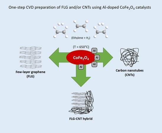
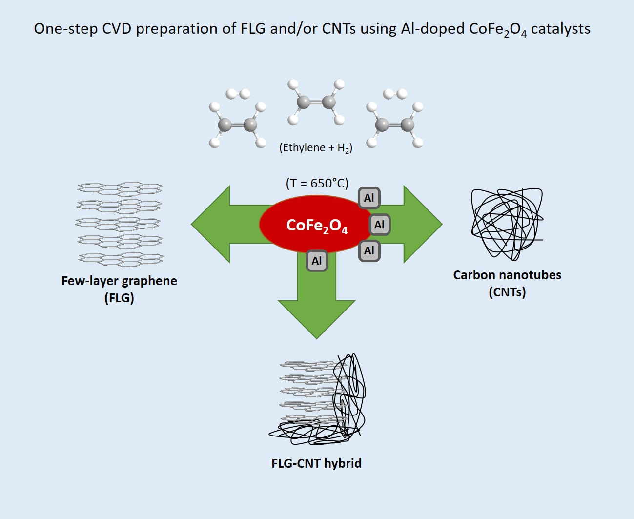
:Functional 3D materials can be developed from graphene-based hybrids by introducing other nanomaterials, with multi-walled carbon nanotubes (CNTs) being the most studied additive. For large-scale applications, few-layer graphene (FLG)-CNT hybrids are produced by catalytic chemical vapor deposition (c-CVD) starting from a mixture of catalysts (one for FLG and one for CNTs) in the required proportions. Due to the difference in growth kinetics between CNTs and FLG, the composition of such hybrids is not well controlled. In this study, we report the single-step preparation of FLG-CNT hybrid materials by a fixed-bed c-CVD process using a single catalyst with the formula AlxCo1−xFe2O4 (x = 0.025–0.10). Different catalysts (with varying x) were prepared by the citrate–nitrate gel combustion method. Then, c-CVD synthesis was carried out at 650 °C in a horizontal fixed-bed reactor using ethylene as the carbon source. Only FLG was obtained when using CoFe2O4. However, the introduction of small amounts of Al (x < 0.05) induced the simultaneous production of CNTs, leading to the formation of uniform FLG-CNT hybrids. For catalysts with higher Al content (e.g., AlCoFeO4), CNTs were selectively produced. Thus, we observed the existence of a narrow Al-doping window, where CNTs and FLG can be obtained simultaneously. Our results can pave the way to developing high-yield single catalyst-based CVD synthesis of FLG-CNT hybrid materials.
1. Introduction
Graphene is an extremely versatile 2D material for nanotechnology applications due to its excellent physical, chemical, and mechanical properties [1,2,3]. Hybrids based on graphene take advantage of these properties to create functional 3D materials by anchoring other nanomaterials on graphene [4,5,6]. Among the different additives, carbon nanotubes (CNTs) are the most studied [7,8]. The high aspect ratio of CNTs in combination with their good electrical conductivity and mechanical properties implies that they can function as an effective connector material between the graphene sheets, creating 3D nanostructures with improved functional properties [9,10,11]. For example, the use of a seamless graphene-CNT (G-CNT) electrode to reversibly store Li metal where dendrite formation was completely suppressed, has been reported recently [12]. Thus, synergy has already been reported between CNTs and graphene or few-layered graphene (FLG) for application in energy [13,14,15], catalysis [16] and electronics [17].
Due to their chemical similarity, there is a strong interaction between CNTs and graphene. Although such interaction is highly favorable for synergy in applications, it also means that properties of the hybrid depend significantly on the preparation method, including the assembling technique used. For large-scale applications, the development of one-step production methods to achieve large volumes of hybrid material with controlled morphology and structure is highly desirable. Several methods have been used for the fabrication of such hybrids, including physical mixing [18], chemical layer-by-layer assembly [19], or growing CNTs on graphene surface [20,21,22]. Simultaneous graphene and CNT growth in a single chemical vapor deposition (CVD) step has also been reported, wherein the CNT growth catalyst was deposited on the graphene growth catalyst [23]. However, a precise control of the hybrid composition in large-scale production of these materials is still far from being optimized.
Here, we report a single-step preparation of FLG-CNT hybrid materials by a catalytic chemical vapor deposition (c-CVD) process to prepare gram-scale quantities of these hybrids. This study is a follow-up of our report on the large-scale CVD synthesis of thickness-controlled FLG [24,25], where we used cobalt ferrite nanoparticles as catalysts to produce FLG with controlled thickness in high yield. It is also interesting to note that ferrites, when supported on alumina or silica, are highly efficient catalysts for CNTs synthesis by CVD [26]. Thus, it should be possible, by suitably controlling the catalyst composition, to develop a single powder catalyst for the c-CVD growth of FLG-CNT hybrids.
Here, we have compared three different c-CVD approaches for the synthesis of FLG-CNT hybrids: (i) using CoFe2O4 catalyst to form FLG, followed by the growth of CNTs on its surface (method-1); (ii) using a physical mixture of FLG and CNT catalysts, followed by the simultaneous growth of CNTs (multi-walled) and FLG; in this case, we have mixed CoFe2O4 (FLG catalyst) with AlCoFeO4, as the latter has been demonstrated to produce CNT in high yield (method-2); and (iii) lastly, we discovered that by doping CoFe2O4 with Al and varying the Al content, FLG-CNT hybrids could be formed from a single catalyst (method-3). We show that doping cobalt ferrite with 0.025 mol of Al leads to the formation of a uniform FLG-CNT hybrid.
2. Materials and Methods
2.1. Catalyst Preparation
Both cobalt ferrite and Al-doped cobalt ferrite (AlxCo1−xFe2O4 with x = 0.025–0.10) were prepared using a previously reported citrate–nitrate gel combustion method [25]. Briefly, appropriate amounts of cobalt(II) nitrate hexahydrate (98+%, Acros Organics, France), iron(III) nitrate nonahydrate (≥98%, Sigma-Aldrich, France), and aluminum nitrate nonahydrate (≥98%, Sigma-Aldrich) were first dissolved in water; the pH of the resulting solution was then adjusted to 6.5–7 using ammonium hydroxide (28.0–30.0% NH3 basis, Sigma-Aldrich). After the gel was formed (furnace at 60 °C overnight), combustion and calcination steps were carried out in a muffle furnace at 200 °C for 2 h and 400 °C for 5 h, respectively. Physical mixtures of catalysts were prepared by ball milling different amounts (25–75%) of CoFe2O4 and AlCoFeO4 for 30 min in a mortar (Pulveriser “Pulverisette”) containing an agate ball (diameter 5 cm).
2.2. c-CVD Synthesis
In a typical experiment, 25 mg of catalyst(s) was inserted in a horizontal fixed-bed reactor and reduced in situ under Ar/H2 (3:1) flow at a temperature of 650 °C for 1 h. Ethylene (30 cm3 min−1) was then introduced for 20 min, after which the reaction products were cooled under Ar. For the two-step synthesis of FLG-CNT hybrid (method-1), CoFe2O4 (FLG catalyst) was first used to form FLG. After the FLG synthesis step, the sample was treated with H2 for 30 min at a reaction temperature of 650 °C to increase catalyst exposure (the metal particles slowly migrated toward the surface of the FLG sheets), after which ethylene was reintroduced resulting in the formation of CNTs on the FLG surface, producing a FLG-CNT hybrid. The yield of the reactions was calculated using the parameter ξ (in gram of purified carbon per gram of catalyst, gC/gcat). The carbon deposits containing reduced catalysts were immersed overnight in 35% HCl at 20 °C to dissolve the catalyst. The carbon powder so obtained was washed with water and dried at 120 °C in air. Analogous to our production method for FLG, it is expected that these processes can be upscaled to operate in a fluidized bed vertical CVD reactor [25].
2.3. Characterization
Low-resolution TEM images were acquired on a JEOL 1011 instrument (Centre Raimond Castaing, Toulouse, France). A FEG Schottky JEOL 2100F analytical electron microscope (Centre Raimond Castaing, Toulouse, France) equipped with a field-emission gun, was used for high-resolution transmission electron microscopy (HRTEM) investigations. X-ray diffractograms were recorded on a Bruker D8 powder diffractometer (Centre Inter-universitaire de Recherche et d’Ingénierie des Matériaux—CIRIMAT, Toulouse, France) equipped with a Göbel mirror in the incident beam and a parallel-slits analyzer in the diffracted beam. The mean crystallite size (Lc) was calculated from the (002) peak, using the Scherrer formula with K = 0.9. Raman spectra were obtained on a Raman micro spectrometer HR 800 Jobin Yvon Horiba (Laboratoire de Chimie de Coordination—LCC, Toulouse, France) using the green line of an Ar laser (λ = 532 nm) as the excitation source. The intensity I (integrated area) and width (full width at half maximum (FWHM)) of the bands were measured using a mixed Gaussian–Lorentzian curve-fitting procedure. N2 adsorption-desorption measurements were carried out at −196 °C using Micrometrics Asap 2010 equipment (Centre d’élaboration de matériaux et d’études structurales—CEMES, Toulouse, France), to determine the Brunauer–Emmett–Teller (BET) specific surface area and obtain information concerning the porosity of the powders. Thermogravimetric analyses (TGA) were conducted under air atmosphere in a Diamond TG/DTA apparatus (LCC, Toulouse, France), with a 10 °C min−1 ramp between 25 and 1000 °C.
3. Results and Discussion
The crystal structure and crystallite sizes of the catalyst were determined from powder X-ray diffractograms (see Figure S1 in the Supplementary Materials). We tested solid solutions with up to 10 mol % Al content and the samples consisted mostly of the ferrite phase, containing only small amounts of AlFe2O4 (<5%). In addition, the introduction of Al in this range did not affect the CoFe2O4 crystallite size (ca. 80 nm). Our previous work on FLG growth from ferrite catalysts has shown that the thickness of the graphene obtained depends critically on the grain size of the ferrite [25], and in the case of the hybrid, it is well known that the diameter and number of walls in CNTs are intimately related to the grain size of the catalyst.
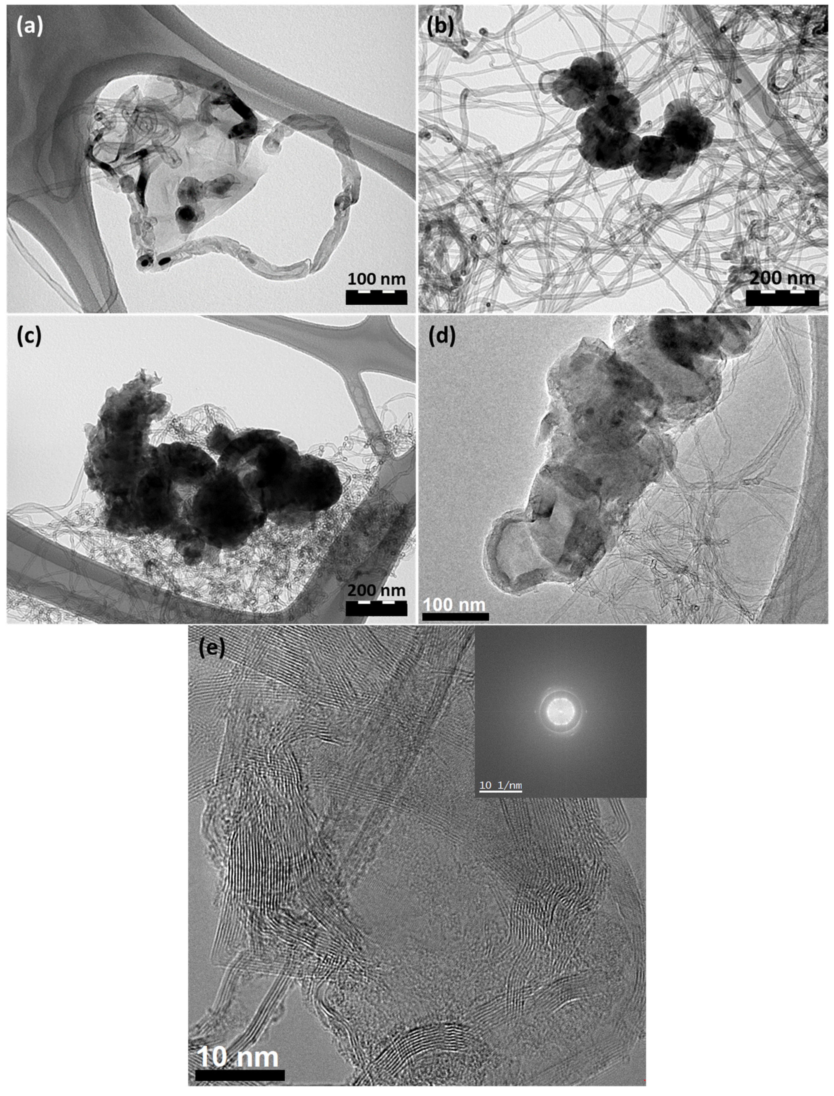
Figure 1 shows TEM images of FLG-CNT hybrids prepared by three different methods. Figure 1a shows CNTs growing out of the surface of a large FLG flake (method-1). Metal particles of various sizes are seen at the CNT tips. This shows that the metal particles have a weak interaction with the graphene layer, due to which, the diameter control of CNTs is not achieved by this method. Figure 1b shows hybrids obtained by mixing CNT and FLG catalysts (ratio 25/75, method-2). The growth of CNTs was not affected by the presence of the FLG catalyst, and thin CNTs (less than 10 walls) were obtained. However, the faster kinetics of the CNT catalyst led to a reduction in the ethylene available for FLG growth. Thus, only isolated islands of thick FLG (5–8 nm) agglomerates were obtained and thus, a thickness control of the FLG cannot be achieved by this method due to the different kinetics of the two catalysts. Independent tests have shown that the FLG catalyst is highly active at the beginning of the reaction. However, CNT growth rate increases after the first five minutes and dominates thereafter. Thus, the final product comprised mainly CNTs with few thick FLG particles. Figure 1c–e shows FLG-CNT hybrids prepared by the c-CVD reaction of ethylene over Al-doped (2.5 mol %) CoFe2O4 single catalyst (method-3). In this case, ethylene was consumed over the catalyst for the simultaneous production of CNTs and FLG. The exact growth mechanism for this method is still under investigation, but based on the uniform structure of the produced CNTs, we do not expect their growth to follow a similar pathway as that observed in method-1. The outer diameter of the nanotubes was uniform in the range of 8–11 nm, whereas the FLG portion retained most of the characteristics shown by the pure FLG (see Figure S2 in the Supplementary Materials). This sample was further characterized to estimate the relative content of FLG and CNTs. In order to study the effect of Al doping on the hybrid structure, a catalyst containing 10 mol % Al (Al0.1Co0.9Fe2O4) was tested as well. In this case, the structure of the hybrid was significantly different, especially the FLG component, resulting in the formation of mostly spherical structures among the CNTs (see Figure S3 in the Supplementary Materials).
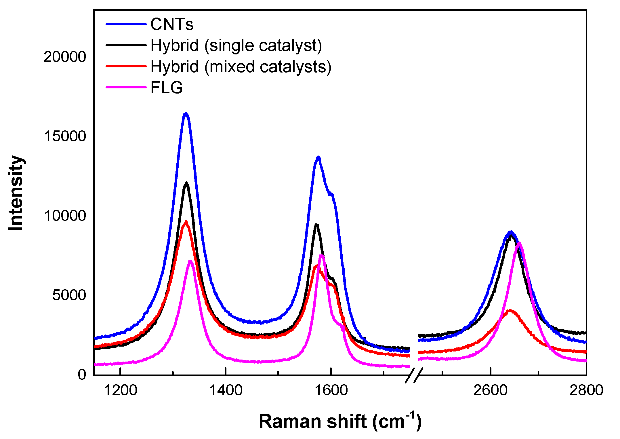
Raman spectra were used to confirm the formation of CNTs and FLG (Figure 2). For pure FLG, the spectra are highly uniform over the entire flake. The narrow G band (ca. 1583 cm−1) shows the existence of a well-crystallized sp2 carbon network. The FWHM of the G band is lowest for pure FLG and is the highest for pure CNTs. Hybrids from both single and mixed catalysts have intermediate values (Table 1). The D (ca. 1334 cm−1) and D’ (1600 cm−1) bands have a relatively high intensity, which could be the result of defects at the edges of smaller flakes; the small area of flakes giving rise to a large number of edges. An intense G′ band (ca. 2660 cm−1) is one of the indications for the presence of FLG. Figure 2 shows a symmetric G′ band with up to 1.2 times the intensity of the G band for FLG, (for the other samples, the G’ band is either equal to or lower than the G band). Moreover, the width of this band is similar to single-layer graphene, suggesting a turbostratic arrangement of the graphene layers [27]. For all the other samples, the G’ band is much broader; all the G′ band positions are distinctly different from graphite (2721 cm−1). All the samples showed high D bands, typical of c-CVD synthesized CNT and FLG [28] in the temperature range of 600–700 °C. For pure CNTs, Raman spectra are similar to those generally observed for multi-walled CVD CNTs [29]. The ID/IG ratio is rather high (1.2) showing a significantly high defect concentration, typical of c-CVD-grown CNTs. For the mixed catalysts, it was not possible to collect a spectrum with both CNT and FLG characteristics, due to the high volume of CNTs with respect to FLG (ID/IG = 1.5). For the hybrid produced from the mixed catalyst, the Raman spectrum resembles that of the CNTs, except that a much broader 2D band was present, presumably due to the presence of FLG. The hybrid material produced using the single catalyst presents an ID/IG ratio of 1.4, similar to that of the hybrid from the mixed catalysts.
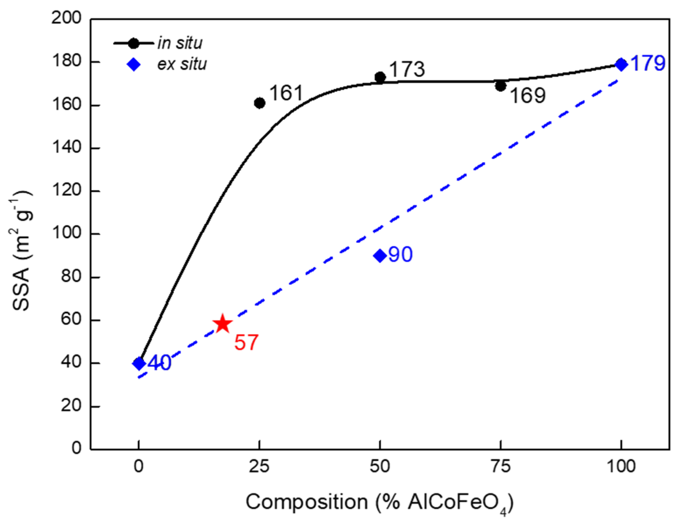
Since both FLG and CNTs are produced from the same catalyst, it is difficult to determine the relative amounts of the two species in a hybrid sample from the Raman spectra; hence, we have carried out a BET surface area study of hybrid materials as a function of the composition (Figure 3). We assume that each component in the sample (CNTs and/or FLG) adsorbs N2 independently of the other, given the significant differences in the pore structure. In such a scenario, the measured BET surface areas of the hybrids of different compositions can be fitted to a calibration curve obtained from the measurements using FLG-CNT mixtures of known composition. Figure 3 shows a plot of the specific surface area (SSA) of the samples formed from a mixture of catalysts versus the percentage of CNT catalyst in the mixture (in situ). We also included the BET surface areas of the pure CNTs (taken as 100% AlCoFeO4), pure FLG (0% AlCoFeO4), and the BET surface area of a physical mixture with equal proportions of FLG and CNT (ex situ). The CNTs obtained using the AlCoFeO4 catalyst reported in this study have a somewhat lower SSA than those synthesized using catalysts such as Fe/Al2O3, which can yield CNTs with 250–300 m2 g−1 [14]. The reason for this lower SSA is currently under investigation, but it could be related to an increased proportion of CNTs with closed caps. Regarding the FLG, this material is several nanometers thick and cannot be exfoliated (as previously reported [25]), and thus, presents a lower SSA than other graphene samples reported in the literature.
From Figure 3, it is seen that the BET surface areas are not linearly correlated, indicating faster kinetics for CNT formation resulting in a significant increase in SSA. The BET surface areas of the samples grown using 25–100% AlCoFeO4 are quite similar, showing the predominance of CNT production. Thus, it is not possible to control the composition of the hybrid using a mixture of catalysts, given the difference in yields between CNTs (74 gCNT/gcat) and FLG (5.1 gFLG/gcat) (Table 2). The FLG-CNT hybrid produced from a mixture of catalysts showed a yield of 25 ghybrid/gcat, whereas the single catalyst produced 5.6 ghybrid/gcat; this relatively slower growth allowed for a better control of the hybrid composition. For the single catalyst with Al content of 2.5 mol %, the BET surface area is 57 m2 g−1, which, according to the calibration curve, should correspond to a hybrid with 17% CNTs and 83% FLG.
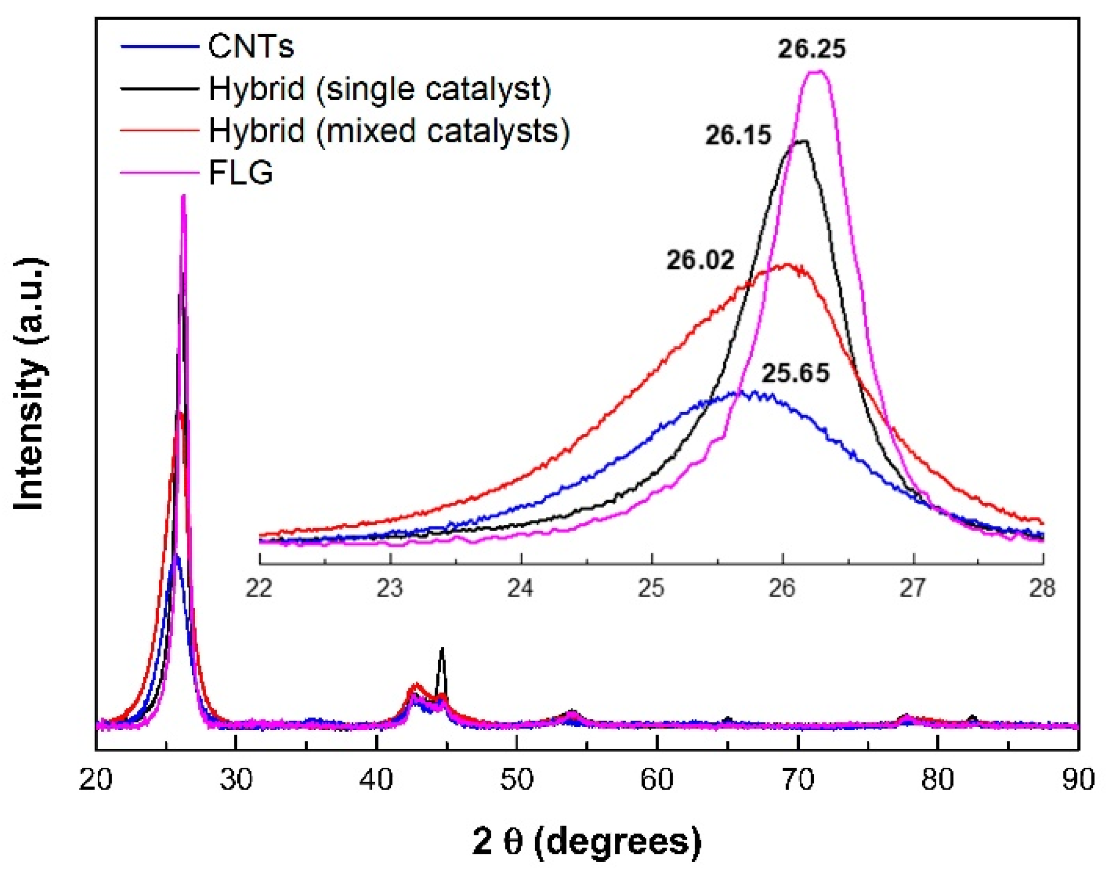
The structures of the CNTs, FLG, and hybrids prepared both from single and mixed catalysts, were investigated by X-ray diffraction (Figure 4). CNTs showed a relatively broad (002) peak at 25.65° (FWHM = 1.66°), whereas, FLG had a narrow one at 26.25° (FWHM = 0.68°), showing a uniform thickness over the sample. The (002) peak shifts to higher angles from CNT to FLG, showing a reduction in d spacing and an increased crystalline order. In contrast to the Raman spectra, the hybrid prepared from a mixture of CNT and FLG catalysts clearly shows both CNT and FLG phases (FWHM = 1.71°). The hybrid prepared from the single catalyst shows a relatively narrow peak (FWHM = 0.85°), similar to the pure FLG, but with a clear shift in the 2θ value, indicating a structure modification for both the FLG and CNTs. A shoulder toward lower angles indicates the presence of CNTs. The peak due to Fe impurity is also seen in this sample. Additional work is required with intermediate compositions to clarify this aspect.
Thermogravimetric analysis results (see Figure S4 in the Supplementary Materials) revealed the relative stability of CNTs, FLG, and the two hybrids to oxidation. Due to the presence of an increased number of defects, such as pentagons at the tube ends, CNTs are oxidized at a lower temperature when compared to FLG. The shape of the first derivative for the hybrid material prepared from mixed catalysts is similar to that of CNTs alone, probably due to the high quantity of CNTs present. Moreover, the samples prepared using different proportions of mixed catalysts (25–75%) revealed only slight differences between the hybrid materials (less than 15 °C). This shows a similarity between these samples, and further confirms the difficulty in controlling the CNT/FLG ratio in a hybrid prepared by mixing catalysts, due to their intrinsically different activities. Additionally, the peak observed for the hybrid prepared from mixed catalysts has a width between that of pure CNTs and FLG. This indicates that the oxidation behavior of the FLG fraction in the hybrid, due to its low amount, does not have a visible impact on the shape of the derivative. By increasing the amount of FLG in the hybrid (i.e., sample prepared from a single catalyst), the oxidation temperature of the sample increased significantly, approaching that of pure FLG, despite presenting a somewhat different shape of the derivative. Hence, two distinct behaviors can be observed: one for materials with high amounts of CNTs, which are oxidized at low temperature, and another for materials with high amounts of FLG, which are oxidized at higher temperatures. Thus, if a good calibration curve is obtained, the FLG/CNT ratio could be determined from TGA as well.
4. Conclusions
We investigated the formation of FLG-CNT hybrid powders by c-CVD using ethylene gas as the carbon source and nanocrystalline ferrite powders as catalyst with the aim to achieve a large-scale catalytic production of hybrids with controlled composition. We have described three different methods for the one-step production of FLG-CNT hybrids. Among the different approaches, the one that resulted in a hybrid with a better FLG/CNT control involved the use of a single catalyst of Al-doped CoFe2O4. Using this strategy, new catalysts for the one-step preparation of FLG-CNT hybrids on a large scale can be achieved. Additional experiments are necessary to determine whether it is possible to further control the hybrid properties (FLG thickness, CNT diameter, etc.) and composition by adjusting operating parameters during the c-CVD synthesis.
Supplementary Materials
The following are available online at https://0-www-mdpi-com.brum.beds.ac.uk/2311-5629/5/2/28/s1, Figure S1: Powder X-ray diffractograms of CoFe2O4, Al0.1Co0.9Fe2O4, and AlCoFeO4 catalysts after calcination at 800 °C, Figure S2: (a) High-resolution TEM micrograph of the FLG-CNT hybrid (scale bar = 10 nm) and (b) electron diffraction pattern of the FLG portion, showing its crystalline nature and rotated graphene planes, as previously reported [1], Figure S3: TEM micrograph of the hybrid material grown from a single catalyst with 10 mol % Al (Al0.1Co0.9Fe2O4) (scale bar = 100 nm)—method-3. Well-graphitized large spheres are seen along with CNTs, Figure S4: (a) TGA curves and (b) TGA first derivative in air atmosphere for CNTs, FLG, and FLG-CNT hybrids obtained from both single catalyst and mixed catalysts.
Author Contributions
B.F.M., C.R.-C., and R.R.B. wrote and edited the manuscript under the close supervision of P.S.
Funding
C.R.-C. thanks CONICYT for financial support (Becas de doctorado en el extranjero “Becas Chile”—n° 72170200).
Acknowledgments
The authors acknowledge Vincent Colliere for his help with HRTEM.
Conflicts of Interest
The authors declare no conflict of interest.
References
- Geim, A.K.; Novoselov, K.S. The rise of graphene. Nat. Mater. 2007, 6, 183. [Google Scholar] [CrossRef] [PubMed]
- Zhu, Y.; Ji, H.; Cheng, H.-M.; Ruoff, R.S. Mass production and industrial applications of graphene materials. Natl. Sci. Rev. 2018, 5, 90–101. [Google Scholar] [CrossRef]
- Rao, C.N.R.; Matte, H.S.S.R.; Subrahmanyam, K.S. Synthesis and Selected Properties of Graphene and Graphene Mimics. Acc. Chem. Res. 2013, 46, 149–159. [Google Scholar] [CrossRef] [PubMed]
- Zhu, Y.; Li, L.; Zhang, C.; Casillas, G.; Sun, Z.; Yan, Z.; Ruan, G.; Peng, Z.; Raji, A.-R.O.; Kittrell, C.; et al. A seamless three-dimensional carbon nanotube graphene hybrid material. Nat. Commun. 2012, 3, 1225. [Google Scholar] [CrossRef] [PubMed]
- Fernandes, D.M.; Novais, H.C.; Bacsa, R.; Serp, P.; Bachiller-Baeza, B.; Rodríguez-Ramos, I.; Guerrero-Ruiz, A.; Freire, C. Polyoxotungstate@Carbon Nanocomposites As Oxygen Reduction Reaction (ORR) Electrocatalysts. Langmuir 2018, 34, 6376–6387. [Google Scholar] [CrossRef]
- Dong, X.; Ma, Y.; Zhu, G.; Huang, Y.; Wang, J.; Chan-Park, M.B.; Wang, L.; Huang, W.; Chen, P. Synthesis of graphene-carbon nanotube hybrid foam and its use as a novel three-dimensional electrode for electrochemical sensing. J. Mater. Chem. 2012, 22, 17044–17048. [Google Scholar] [CrossRef]
- Xia, K.; Zhan, H.; Gu, Y. Graphene and Carbon Nanotube Hybrid Structure: A Review. Procedia IUTAM 2017, 21, 94–101. [Google Scholar] [CrossRef]
- Dasgupta, A.; Rajukumar, L.P.; Rotella, C.; Lei, Y.; Terrones, M. Covalent three-dimensional networks of graphene and carbon nanotubes: Synthesis and environmental applications. Nano Today 2017, 12, 116–135. [Google Scholar] [CrossRef]
- Badhulika, S.; Terse-Thakoor, T.; Chaves Villarreal, C.; Mulchandani, A. Graphene hybrids: Synthesis strategies and applications in sensors and sensitized solar cells. Front. Chem. 2015, 3, 38. [Google Scholar] [CrossRef]
- Fan, W.; Zhang, L.; Liu, T. Strategies for the Hybridization of CNTs with Graphene. In Graphene-Carbon Nanotube Hybrids for Energy and Environmental Applications; Springer: Singapore, 2017; pp. 21–51. [Google Scholar]
- Eswaraiah, V.; Jyothirmayee Aravind, S.S.; Balasubramaniam, K.; Ramaprabhu, S. Graphene-Functionalized Carbon Nanotubes for Conducting Polymer Nanocomposites and Their Improved Strain Sensing Properties. Macromol. Chem. Phys. 2013, 214, 2439–2444. [Google Scholar] [CrossRef]
- Raji, A.-R.O.; Villegas Salvatierra, R.; Kim, N.D.; Fan, X.; Li, Y.; Silva, G.A.L.; Sha, J.; Tour, J.M. Lithium Batteries with Nearly Maximum Metal Storage. ACS Nano 2017, 11, 6362–6369. [Google Scholar] [CrossRef] [PubMed] [Green Version]
- Maarouf, A.A.; Kasry, A.; Chandra, B.; Martyna, G.J. A graphene–carbon nanotube hybrid material for photovoltaic applications. Carbon 2016, 102, 74–80. [Google Scholar] [CrossRef]
- Machado, B.F.; Marchionni, A.; Bacsa, R.R.; Bellini, M.; Beausoleil, J.; Oberhauser, W.; Vizza, F.; Serp, P. Synergistic effect between few layer graphene and carbon nanotube supports for palladium catalyzing electrochemical oxidation of alcohols. J. Energy Chem. 2013, 22, 296–304. [Google Scholar] [CrossRef]
- Wang, D.; Fang, G.; Zheng, Q.; Geng, G.; Ma, J. Construction of hierarchical porous graphene–carbon nanotubes hybrid with high surface area for high performance supercapacitor applications. J. Solid State Electrochem. 2017, 21, 563–571. [Google Scholar] [CrossRef]
- Axet, M.R.; Bacsa, R.R.; Machado, B.F.; Serp, P. Adsorption on and Reactivity of Carbon Nanotubes and Graphene. In Handbook of Carbon Nano Materials; World Scientific Publishing: Singapore, 2014; pp. 39–183. [Google Scholar]
- Darmawan, C.C.; Ye, L.; Samani, M.K.; Fu, Y.; Liu, J. Graphene-CNT hybrid material as potential thermal solution in electronics applications. In Proceedings of the 2017 IMAPS Nordic Conference on Microelectronics Packaging (NordPac), Gothenburg, Sweden, 18–20 June 2017; pp. 190–193. [Google Scholar]
- Li, W.; Dichiara, A.; Bai, J. Carbon nanotube–graphene nanoplatelet hybrids as high-performance multifunctional reinforcements in epoxy composites. Compos. Sci. Technol. 2013, 74, 221–227. [Google Scholar] [CrossRef]
- Patel, S.C.; Alam, O.; Zhang, D.; Grover, K.; Qin, Y.-X.; Sitharaman, B. Layer-by-layer, ultrasonic spray assembled 2D and 3D chemically crosslinked carbon nanotubes and graphene. J. Mater. Res. 2017, 32, 370–382. [Google Scholar] [CrossRef]
- Rao, R.; Chen, G.; Arava, L.M.R.; Kalaga, K.; Ishigami, M.; Heinz, T.F.; Ajayan, P.M.; Harutyunyan, A.R. Graphene as an atomically thin interface for growth of vertically aligned carbon nanotubes. Sci. Rep. 2013, 3, 1891. [Google Scholar] [CrossRef] [Green Version]
- Dong, X.; Li, B.; Wei, A.; Cao, X.; Chan-Park, M.B.; Zhang, H.; Li, L.-J.; Huang, W.; Chen, P. One-step growth of graphene–carbon nanotube hybrid materials by chemical vapor deposition. Carbon 2011, 49, 2944–2949. [Google Scholar] [CrossRef]
- Jiang, J.; Li, Y.; Gao, C.; Kim, N.D.; Fan, X.; Wang, G.; Peng, Z.; Hauge, R.H.; Tour, J.M. Growing Carbon Nanotubes from Both Sides of Graphene. ACS Appl. Mater. Interfaces 2016, 8, 7356–7362. [Google Scholar] [CrossRef]
- Kumar, K.; Kim, Y.-S.; Li, X.; Ding, J.; Fisher, F.T.; Yang, E.-H. Chemical Vapor Deposition of Carbon Nanotubes on Monolayer Graphene Substrates: Reduced Etching via Suppressed Catalytic Hydrogenation Using C2H4. Chem. Mater. 2013, 25, 3874–3879. [Google Scholar] [CrossRef]
- Bacsa, R.; Serp, P.; Lecante, P.; Pavlenko, E.; Cameán, I.; Ramos, A.; Garcia, A.B.; Bacsa, W.S. Interlayer interaction and disorder in few layer graphene powders prepared by fluidized bed chemical vapor deposition. In Proceedings of the Nanotech 2014, Washington, DC, USA, 15–18 June 2014; pp. 68–71. [Google Scholar]
- Bacsa, R.R.; Cameán, I.; Ramos, A.; Garcia, A.B.; Tishkova, V.; Bacsa, W.S.; Gallagher, J.R.; Miller, J.T.; Navas, H.; Jourdain, V.; et al. Few layer graphene synthesis on transition metal ferrite catalysts. Carbon 2015, 89, 350–360. [Google Scholar] [CrossRef] [Green Version]
- Corrias, M.; Kihn, Y.; Kalck, P.; Serp, P. CVD from ethylene on cobalt ferrite catalysts: The effect of the support. Carbon 2005, 43, 2820–2823. [Google Scholar] [CrossRef]
- Ferrari, A.C.; Meyer, J.C.; Scardaci, V.; Casiraghi, C.; Lazzeri, M.; Mauri, F.; Piscanec, S.; Jiang, D.; Novoselov, K.S.; Roth, S.; et al. Raman Spectrum of Graphene and Graphene Layers. Phys. Rev. Lett. 2006, 97, 187401. [Google Scholar] [CrossRef] [PubMed] [Green Version]
- Serp, P.; Machado, B.F. Nanostructured Carbon Materials for Catalysis; Royal Society of Chemistry: Croydon, UK, 2015; p. 570. [Google Scholar]
- Dresselhaus, M.S.; Dresselhaus, G.; Eklund, P.C. Science of Fullerenes and Carbon Nanotubes; Academic Press: Cambridge, MA, USA, 1996; p. 965. [Google Scholar]
Figure 1.
TEM micrographs of (a) carbon nanotubes (CNTs) growing out of the surface of a few-layer graphene (FLG) flake—method-1 (scale bar = 100 nm); (b) CNTs and FLG grown from a mixture of AlCoFeO4 and CoFe2O4 catalysts, respectively—method-2 (scale bar = 200 nm); (c) (scale bar = 200 nm) and (d) (scale bar = 100 nm) FLG-CNT hybrid material grown from a single catalyst (Al0.025Co0.975Fe2O4)—method-3; (e) high-resolution transmission electron microscopy (HRTEM) micrograph of the hybrid shown in (c) and (d) (scale bar = 10 nm); inset shows the corresponding electron diffraction pattern.

Figure 2.
Raman spectra at room temperature of CNTs, FLG, and FLG-CNT hybrids produced from single and mixed catalysts (λexc = 532 nm).
Figure 2.
Raman spectra at room temperature of CNTs, FLG, and FLG-CNT hybrids produced from single and mixed catalysts (λexc = 532 nm).

Figure 3.
Variation in BET surface area of the FLG-CNT hybrids formed from a mixture of catalysts (in situ) as a function of added AlCoFeO4 (CNT catalyst). The dashed line (in blue) is obtained by measuring the BET surface area of physical mixtures of CNTs and FLG (ex situ). The star (in red) represents the BET surface area of the hybrid prepared from the single catalyst.

Figure 4.
Powder X-ray diffractograms of pure CNTs and FLG, together with those of FLG–CNT hybrids obtained from a single catalyst and from a mixture of CNT and FLG catalysts. Inset shows the (002) peak for all the samples.
Figure 4.
Powder X-ray diffractograms of pure CNTs and FLG, together with those of FLG–CNT hybrids obtained from a single catalyst and from a mixture of CNT and FLG catalysts. Inset shows the (002) peak for all the samples.


Table 1.
Full width at half maximum (FWHM) for D, G and G’ bands, and ID/IG and IG/IG’ ratios from Raman spectroscopy for purified CNTs, FLG–CNT hybrids, and FLG.
Table 1.
Full width at half maximum (FWHM) for D, G and G’ bands, and ID/IG and IG/IG’ ratios from Raman spectroscopy for purified CNTs, FLG–CNT hybrids, and FLG.
| Sample | FWHMD (cm−1) | FWHMG * (cm−1) | FWHMG’ (cm−1) | ID/IG | IG/IG’ |
|---|---|---|---|---|---|
| CNTs | 53.9 | 67.7 | 81.4 | 1.18 | 1.71 |
| FLG-CNT hybrid (mixed catalysts) | 53.9 | 64.5 | 75.1 | 1.48 | 2.03 |
| FLG-CNT hybrid (single catalyst) | 47.4 | 52.7 | 62.2 | 1.36 | 1.19 |
| FLG | 42.3 | 32.8 | 56.0 | 0.92 | 0.94 |
* Given that the G band includes the contribution of two peaks, the corresponding full width at half maximum (FWHM) was determined by deconvolution.
Table 2.
Yield, ash content determined by TGA, Brunauer–Emmett–Teller (BET) specific surface area calculated from N2 adsorption-desorption at −196 °C, and d002 peak parameters from XRD for purified CNTs, FLG–CNT hybrids, and FLG.
Table 2.
Yield, ash content determined by TGA, Brunauer–Emmett–Teller (BET) specific surface area calculated from N2 adsorption-desorption at −196 °C, and d002 peak parameters from XRD for purified CNTs, FLG–CNT hybrids, and FLG.
| Sample | Yield (gC gcat−1) | Ash Content (wt.%) | SBET (m2 g−1) | d002 | |
|---|---|---|---|---|---|
| FWHM | Center | ||||
| CNTs | 74 | 3.9 | 179 | 1.66 | 25.65 |
| FLG-CNT hybrid (mixed catalysts) | 25 | 2.8 | 161 | 1.71 | 26.02 |
| FLG-CNT hybrid (single catalyst) | 5.6 | 4.0 | 57 | 0.85 | 26.15 |
| CNT@FLG | 6.2 | - | - | - | - |
| FLG | 5.1 | <1.0 | 40 | 0.68 | 26.25 |
© 2019 by the authors. Licensee MDPI, Basel, Switzerland. This article is an open access article distributed under the terms and conditions of the Creative Commons Attribution (CC BY) license (http://creativecommons.org/licenses/by/4.0/).
Share and Cite
MDPI and ACS Style
Machado, B.F.; Bacsa, R.R.; Rivera-Cárcamo, C.; Serp, P. Preparation of Few-Layer Graphene/Carbon Nanotube Hybrids Using Oxide Spinel Catalysts. C 2019, 5, 28. https://0-doi-org.brum.beds.ac.uk/10.3390/c5020028
AMA Style
Machado BF, Bacsa RR, Rivera-Cárcamo C, Serp P. Preparation of Few-Layer Graphene/Carbon Nanotube Hybrids Using Oxide Spinel Catalysts. C. 2019; 5(2):28. https://0-doi-org.brum.beds.ac.uk/10.3390/c5020028
Chicago/Turabian StyleMachado, Bruno F., Revathi R. Bacsa, Camila Rivera-Cárcamo, and Philippe Serp. 2019. "Preparation of Few-Layer Graphene/Carbon Nanotube Hybrids Using Oxide Spinel Catalysts" C 5, no. 2: 28. https://0-doi-org.brum.beds.ac.uk/10.3390/c5020028
Note that from the first issue of 2016, this journal uses article numbers instead of page numbers. See further details here.