Chemical Recycling of Consumer-Grade Black Plastic into Electrically Conductive Carbon Nanotubes


1
Energy Safety Research Institute, Swansea University, Bay Campus, Swansea SA1 8EN, UK
2
Chalmers University of Technology, Division of Energy Technology, Hörsalsvägen 7B, 412 58 Göteborg, Sweden
*
Author to whom correspondence should be addressed.
C 2019, 5(2), 32; https://0-doi-org.brum.beds.ac.uk/10.3390/c5020032
Submission received: 15 March 2019
/
Revised: 13 May 2019
/
Accepted: 14 May 2019
/
Published: 12 June 2019
(This article belongs to the Collection Carbon in the Circular Economy)
Abstract
:The global plastics crisis has recently focused scientists’ attention on finding technical solutions for the ever-increasing oversupply of plastic waste. Black plastic is one of the greatest contributors to landfill waste, because it cannot be sorted using industrial practices based on optical reflection. However, it can be readily upcycled into carbon nanotubes (CNTs) using a novel liquid injection reactor (LIR) chemical vapor deposition (CVD) method. In this work, CNTs were formed using black and white polystyrene plastics to demonstrate that off-the-shelf materials can be used as feedstock for growth of CNTs. Scanning electron microscopy analysis suggests the CNTs from plastic sources improve diameter distribution homogeneity, with slightly increased diameters compared with control samples. Slight improvements in quality, as determined by Raman spectroscopy of the D and G peaks, suggest that plastics could lead to increased quality of CNTs. A small device was constructed as a demonstrator model to increase impact and public engagement.
1. Introduction
Black plastic is an extremely common material that is used on a global scale. It is usually made of recycled plastics with added black pigments to hide or mask the colors of the original plastics. All colored plastics can be made into black plastic but not the other way around. Unfortunately, it has become the last step in a short chain of use and reuse before going to a landfill. Despite the fact that the chemistry of the plastic may allow for further recycling, it cannot be identified using optical sorting systems due to high absorptivity. Therefore, black plastics are left with all the undesirable materials at the end of the rubbish sorting system, and this all goes to landfill. In one sense, black plastic is the final resting state for plastics as they pass through a short consumer cycle from birth to eventual death in a landfill or microplastic near you. Until a technical solution is found for sorting the plastics more effectively, or legislation is introduced to prevent black plastic use, it will continue to go from supermarket shelves to landfills in very rapid order. Food suppliers typically use polystyrene plastics because of its soft texture and durability. In addition, the black color contrast makes food look fresher while also hiding blood that would otherwise be unappetizing.
Polystyrene (PS) and expandable polystyrene (EPS) can be recycled, and every year, thousands of tons of EPS are recycled mainly into polystyrene balls, which are used for coat hangers, picture frames, replacement hardwood and CD cases. Alternatively, it can be burned in a heat recovery system due to the calorific value of plastics (1 kg of PS is equal to 1.3 L of heating fuel). However, landfilling and incineration can cause further environmental damage such as land, air and sea pollution [1]. In 2015 alone, 17 million metric tons (Mt) of PS was produced globally; 90% has been discarded, and less than 20% has been recycled [2]. Therefore, new solutions are sought to alleviate the spread of PS.
A circular economy is required for plastics, particularly for the carbon in the plastics. Until then, plastic waste will continue to increase along with the consequences (increased CO2 emission, microplastic formation). This requires new avenues for carbon after the first life of the plastic. Chemical upcycling into carbon nanotubes (CNTs) is a favorable route due to their long life and their beneficial thermal, mechanical [3] and electrical properties [4]. CNTs are a high-value material compared with waste carbon, thus offering the potential to increase the value of the plastic as a commodity material for CNT growth. CNTs are typically made using refined carbon sources, such as toluene [5], naphthalene [6], methane, ethane, etc. However, CNTs can be made from non-conventional hydrocarbons [7] and plastics. Effectually, plastics are highly refined carbon sources, so they can act as excellent feedstock for the growth of carbon nanotubes. Typically, the growth of CNTs from plastics has been achieved using pyrolysis [8]. Polymers, such as polypropylene (PP) [9], polyethylene (PE) [10] and polyethylene terephthalate (PET) [11], are heated in a solid–gas fluidized bed reactor [12]. The resultant off-gas (carbon source) is traversed to a catalyst site to complete the reaction. However, a black carbon char residue forms as a by-product, resulting in low overall yields, because much of the original plastic mass becomes charred and is unreacted. This would suggest that large-scale applications are not economical due to this inefficiency, in addition to the fact that the black char is another waste material that must also be dealt with [13].
There is a question as to the nature of the carbon source and its appropriateness for making nanotubes in an environmental [14] and chemical context. Carbon from various sources can be used to make nanotubes once the following four basic requirements are satisfied: (1) The carbon is delivered to the catalyst site. (2) The carbon supply is delivered in a controlled fashion [15], oversupply often leads to a larger number of walls (“Puretzky model”) [16], or it can quench the catalyst. (3) The catalyst is activated (typically in a reducing atmosphere) and becomes an appropriate size [17], shape and chemical composition [18]. (4) Growth temperature matches the thermal decomposition temperature of the carbon source(s) [19]. In this work, we show that polystyrene (black and white) from commercial sources contributes to the growth of multi-walled carbon nanotubes.
2. Materials and Methods
Multi-walled carbon nanotubes (MWCNTs) were grown via catalytic chemical vapor deposition (CCVD) in a two-zoned horizontal liquid injection reactor (LIR); full details are described elsewhere [5]. In brief, CNT samples were grown at 780 °C by injection of 3–5 mL of solution at 1–3 mL/h under gas flow of 1 L/min using a gas composition of 5% H2 in argon balance. MWCNTs were grown in a 100-cm-long quartz tube with an internal diameter of 38 mm obtained from Multi-Lab U.K. Solutions containing ferrocene were used as catalysts in a concentration of 5 wt.% in toluene solvent. PS (16.5 mg) materials were dissolved in toluene prior to injection to the LIR. Plastic materials were used from commercial sources. The black plastic food packaging was bought at a local grocery store and then cleaned using soap and water prior to inclusion in this work. White plastic weigh boats (Sigma Aldrich Co, The Old Brickyard, New Rd, Gillingham, UK) were used as a white plastic source.
The structure and purity of the CNTs were analyzed using a Renishaw inVia Raman Microscope (Renishaw plc, Miskin, Pontyclun, UK). Laser beam at 633 nm wavelength and 5% beam power was used for data acquisition between 100 and 3200 cm−1. Raman data was acquired at a minimum of 5 times per sample. Each time, it was probed at a new location to test variability across each sample. All samples were tested when maximum G peak intensity had been established to ensure the best signal-to-noise ratio and to ensure comparability between spectra. The morphology and diameter of the CNTs were analyzed by images obtained from a JEOL 7800F FEG SEM (JEOL, Akishima, Tokyo, Japan). Images were acquired at an operating voltage of 5 kV, with a working distance of 10 mm. A small fraction of each sample was suspended in 3 mL of ethanol, and 100 µL of the suspension was dried on the surface of a clean silicon wafer for SEM imaging [20]. ImageJ (version 1.50i) [21] was used to measure CNT diameters.
CNT thin films were prepared using “buckypaper” technique [22] to demonstrate the electrical conductivity. In preparation, the CNTs were acid washed by nitric acid at 70 °C for 24 h at reflux to remove catalyst. Following acid treatment, the CNTs were suspended in isopropanol, and films were made using vacuum filtration [23]. The CNT films were dried at 80 °C for 3 h prior to testing as an electrical circuit.
3. Results and Discussion
Scanning electron microscopy was used to determine the morphology of the samples grown in this study (Figure 1). In all cases, CNTs were observed and their diameters measured using ImageJ (version 1.50i). It was found that the control samples had a typical size of 30–40 nm diameters but had a very large range. In some images, nanotubes with possible 400 nm were observed, this could be due to the presence of graphitic fibers, such as vapor-grown fibers in the sample that are very similar in appearance when observed in an SEM. Vapor-grown fibers are known to form in certain reaction conditions when preparing MWCNTs in CVD reactions based on the floating catalyst [5] method. Coarsening of the catalyst material, leading to larger catalysts, could be responsible for the formation of large fibers. However, upon using polystyrene, the diameter distributions appeared more homogeneous and in no cases were nanotubes observed with diameters larger than 120 nm. This would suggest that the presence of the polymer material may affect the catalyst during growth, possibly preventing coarsening or Ostwald ripening from occurring. The oligomeric material may act as a surfactant, thereby lowering the energy states of the catalyst surface that otherwise readily coalesce in a highly energetic environment such as in the CVD process. However, we also note that the diameters did increase from an average of 38.7 to 43.5 nm (white PS) and 41.3 nm (black PS). This increase in diameter is consistent with the “Puretzky model” of CNT growth, whereby an increased flux of carbon to the catalyst would lead to the formation of larger-diameter nanotubes. The complete role and effect of the polymer towards the growth of CNTs is yet to be determined, and further work dealing with polymers of varying molecular weight is to be carried out in the near future. We also note that white particles, as visualized in the SEM, were apparent throughout all the samples in this study, which we suggest were residual catalyst material. This has been observed in similar reactions previously [5].
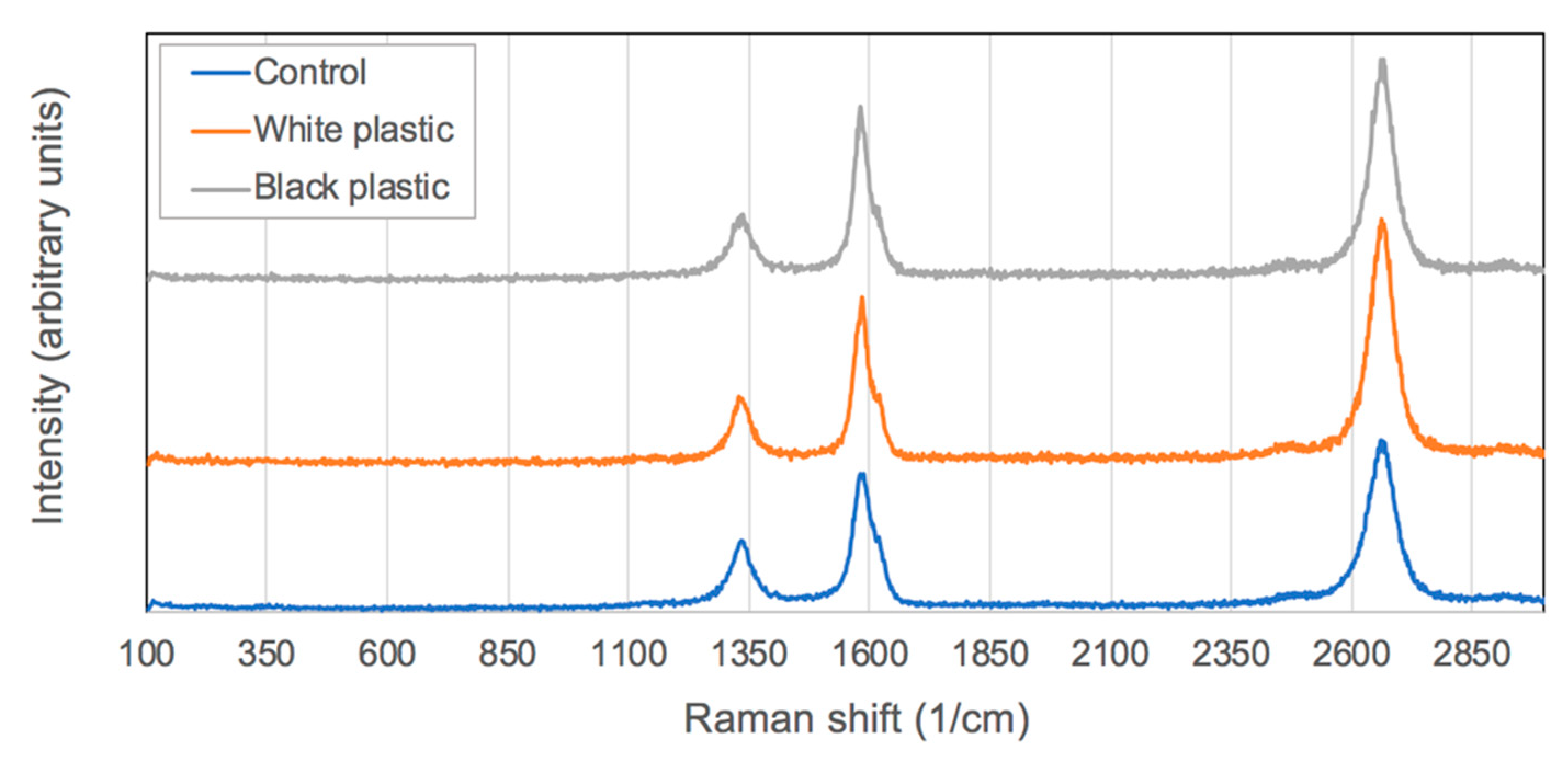
Raman spectroscopy was used to confirm the CNT presence by observation of typical fingerprint peaks, namely the D, G and 2D peaks. The D peak (~1350 cm−1) is called so because the sp3 carbons are usually attributed to defects/disorder in the wall structure. The presence of a D peak is practically unavoidable in the case of MWCNT samples. Even the tips of the CNTs having pentane members with sp3 carbons will also contribute to the D peak intensity. In Figure 2, all the D peaks were normalized to allow for ready comparison between each spectrum from the various samples. Often the most reported value in Raman spectroscopy of CNTs is the relative intensities of the G/D peaks. The G peak (~1570 cm−1) originates from the presence of sp2 carbon atoms that is associated with graphitic domains or graphitic structure compounds. Therefore, a comparison of the sp2/sp3 (G/D peak) carbons is used as a metric to determine the relative quality of CNT samples, as it is expected that carbon nanotubes would have a larger quantity of sp2 carbons compared with sp3 carbons. The larger the value, the greater the quality of the product. As can be seen in Table 1, the maximum intensity of the G/D values was highest for the case using black plastic as a carbon source.
It should be noted that graphite material is often used as a pigment in the creation of black plastic, and unreacted graphite could contribute to the signal intensity at the G peak. For this reason, growth was also carried out using white polystyrene as a comparison. White polystyrene will have the same polymer material, without the presence of graphite pigment that may affect the Raman data. As shown in Table 1, the maximum G/D ratio of white PS was 2.4, and that of black PS was 2.5. These values are very similar to one another, suggesting that the graphite pigment does not contribute to the larger G peak intensity, as it is so similar to the value obtained in the growth using white PS. Therefore, we suggest the values are indicative of CNTs and not some other external contributing factor. This leads to the conclusion that growth from PS materials, under the conditions used in this study, resulted in improved crystal quality of materials.
The third and final fingerprint peak associated with MWCNTs is the 2D or G’ peak (~2700 cm−1). This is associated with the number of walls in the nanotube structure, whereby a larger number of walls can result in a higher relative intensity of the 2D peak. In Figure 2, it is evident that the largest 2D peak arose in the case of white PS samples. This is consistent with the SEM data that showed the white PS sample to have the largest diameters of 43.5 nm (compared with black PS CNT samples having average diameters of 41.3 nm).
One of the most touted potential applications of CNTs is in the electrical industry. Long standing efforts [24] have sought to create a wire composed of carbon nanotubes that can replace traditional copper materials. Seeing is believing, and in the case of electrical conduction through carbon nanotubes, seeing lights turn on has maximum impact with audiences everywhere. The plastics problem is a global crisis, and small wins like this help to engender a sense of hope and optimism that is fundamentally required in order to solve this pressing challenge. This is especially important where scientific projects and funding bodies are measuring impact to decide future funding rounds. To this end, a small circuit was created that can demonstrate the capacity for carbon nanotubes to act as electricity conductors [25]. This small demonstration (Figure 3) proves the point that carbon nanotubes are low-resistance materials, and even small power sources such as batteries are powerful enough to irradiate a small light bulb through a CNT circuit. Moreover, witnesses can see that the bulb intensity has negligible change when run through the nanotube materials.
4. Conclusions
Plastics were readily dissolved in toluene/ferrocene solvent and injected into the liquid injection reactor. Carbon nanotube growth was mildly affected by the inclusion of polystyrene plastics in the feedstock based on three noticeable changes to the CNT properties: (1) The diameters became more monodisperse in size, (2) the diameters were larger when using plastics in the feedstock, and (3) an improved G/D ratio was observed, albeit small, which indicates that the plastics do not deteriorate the CNT products. This suggests that under specific conditions, the addition of plastics in the feedstock solution could potentially improve the properties of the CNT products, and at the very least, it does not degrade the properties of the CNTs. We conclude that commercial sources of waste plastic can be converted into MWCNTs via this chemical recycling process and this opens up the possibility to close the loop on the circular economy of plastics. Future work will be carried out in order to establish the full extent to which plastics affect or contribute to the growth process and to learn about how plastics affect the properties of subsequent CNTs from which they are grown.
Author Contributions
Article written by A.H. and A.O.W. Concept designed by A.O.W. Experimental designed by A.H. and A.O.W. Experiments and data acquisition carried out by A.H. Data analysis carried out by A.H., G.S., A.O.W. Additional measurements carried out by C.J.B.
Funding
A.O.W. is funded through Sêr Cymru Fellowship by the European Regional Development Fund (ERDF) and the Welsh Government. A.H. was funded by the Copper Nanotube Ultraconductive (UCC) wire project funded by Sêr Cymru National Research Network for Advanced Engineering and Materials (NRN) with contributions from E-Corp. G.S. received funding from Swansea University Employability Academy (SEA) through their summer placements scheme. C.J.B. was funded by Flexis which is part-funded by the European Regional Development Fund (ERDF), through the Welsh Government.
Acknowledgments
Thank you to Ewa Kazimierska for help with pictures of white plastic materials. We would like to acknowledge the assistance provided by Swansea University College of Engineering AIM Facility, which was funded in part by the EPSRC (EP/M028267/1), the European Regional Development Fund through the Welsh Government (80708) and the Sêr Solar project via Welsh Government.
Conflicts of Interest
The authors declare no conflicts of interest.
References
- Keswani, A.; Oliver, D.M.; Gutierrez, T.; Quilliama, R.S. Microbial hitchhikers on marine plastic de-bris: Human exposure risks at bathing waters and beach environments. Mar. Environ. Res. 2016, 118, 10–19. [Google Scholar] [CrossRef] [PubMed]
- Rahimi, A.; García, J.M. Chemical Recycling of Waste Plastics for New Materials Production. Nat. Rev. Chem. 2017, 1, 0046. [Google Scholar] [CrossRef]
- Liu, X.; Sun, H.; Wu, C.; Patel, D.; Huang, J. Thermal Chemical Conversion of High-Density Polyethylene for the Production of Valuable Carbon Nanotubes Using Ni/AAO Membrane Catalyst. Energy Fuels 2018, 32, 4511–4520. [Google Scholar] [CrossRef]
- Deng, J.; You, Y.; Sahajwalla, V.; Joshi, R.K. Transforming waste into carbon-based nanomaterials. Carbon 2016, 96, 105–115. [Google Scholar] [CrossRef]
- Orbaek, A.W.; Aggarwal, N.; Barron, A.R. The development of a ‘process map’ for the growth of carbon nanomaterials from ferrocene by injection CVD. J. Mater. Chem. A. 2013, 1, 14122–14132. [Google Scholar] [CrossRef]
- Puengjinda, P.; Sano, N.; Tanthapanichakoon, W.; Charinpanitkul, T. Selective synthesis of carbon nanotubes and nanocapsules using naphthalene pyrolysis assisted with ferrocene. J. Ind. Eng. Chem. 2009, 15, 375–380. [Google Scholar] [CrossRef]
- Kumar, R.; Singh, R.K.; Singh, D.P. Natural and Waste Hydrocarbon Precursors for the Synthesis of Carbon Based Nanomaterials: Graphene and CNTs. Renew. Sustain. Energy Rev. 2016, 58, 976–1006. [Google Scholar] [CrossRef]
- Acomb, J.C.; Wu, C.; William, P.T. Control of steam input to the pyrolysis-gasification of waste plastics for improved production of hydrogen or carbon nanotubes. Appl. Catal. B Environ. 2014, 147, 571–584. [Google Scholar] [CrossRef]
- Bajad, G.S.; Tiwari, S.K.; Vijayakumar, R.P. Synthesis and characterization of CNTs using polypropylene waste as precursor. Mater. Sci. Eng. B 2015, 194, 68–77. [Google Scholar] [CrossRef]
- Aboul-Enein, A.A.; Adel-Rahman, H.; Haggar, A.M.; Awadallah, A.E. Simple method for synthesis of carbon nanotubes over NiMo/Al2O3 catalyst via pyrolysis of polyethylene waste using a two-stage process. Fuller. Nanotub. Carbon Nanostructures 2017, 25, 211–222. [Google Scholar] [CrossRef]
- El Essawy, N.A.; Konsowa, A.H.; Elnouby, M.; Farag, H.A. A novel one-step synthesis for carbon-based nanomaterials from polyethylene terephthalate (PET) bottles waste. J. Air Waste Manag. Assoc. 2017, 67, 358–370. [Google Scholar] [CrossRef] [PubMed]
- Arena, U.; Mastellone, M.L.; Camino, G.; Boccaleri, E. An innovative process for mass production of multi-wall carbon nanotubes by means of low-cost pyrolysis of polyolefins. Polym. Degrad. Stab. 2006, 91, 763–768. [Google Scholar] [CrossRef]
- Hedayati, A.; Swan, G.; Orbaek White, A. Improved method for the facile chemical recycling of plastics into multiwalled carbon nanotubes. RSC Adv. 2019. in preparation. [Google Scholar]
- Shi, W.; Plata, D. Vertically aligned carbon nanotubes: Production and applications for environmental sustainability. Green Chem. 2018, 20, 5245–5260. [Google Scholar] [CrossRef]
- Orbaek, A.W.; Owens, A.C.; Barron, A.R. Increasing the Efficiency of Single Walled Carbon Nanotube Amplification by Fe-Co Catalysts through the Optimization of CH4/H2 Partial Pressures. Nano Lett. 2011, 11, 2871–2874. [Google Scholar] [CrossRef] [PubMed]
- Wood, R.F.; Pannala, S.; Wells, J.C.; Puretzky, A.A.; Geohegan, D.B. Simple Model of the Interrelation between Single- and Multiwall Carbon Nanotube Growth Rates for the CVD Process. Phys. Rev. B 2007, 75, 235446. [Google Scholar] [CrossRef]
- Orbaek, A.W.; Morrow, L.; Maguire-Boyle, S.J.; Barron, A.R. Reagent Control over the Composition of Mixed Metal Oxide Nanoparticles. J. Exp. Nanosci. 2013, 10, 324–349. [Google Scholar] [CrossRef]
- Orbaek, A.W.; Owens, A.C.; Crouse, C.C.; Pint, C.L.; Hauge, R.H.; Barron, A.R. Single Walled Carbon Nanotube Growth and Chirality Dependence on Catalyst Composition. Nanoscale 2013, 5, 9848–9859. [Google Scholar] [CrossRef]
- Orbaek, A.W.; Barron, A.R. Towards a ‘Catalyst Activity Map’ Regarding the Nucleation and Growth of Single Walled Carbon Nanotubes. J. Exp. Nanosci. 2013. [Google Scholar] [CrossRef]
- Orbaek, A.W.; Barron, A.R. Complications Pertaining to the Detection and Characterization of Individual and Embedded Single Walled Carbon Nanotubes by Scanning Electron Microscopy. Nanoscale 2013, 5, 2790–2797. [Google Scholar] [CrossRef]
- Rueden, C.T.; Schindelin, J.; Hiner, M.C. ImageJ2: ImageJ for the next generation of scientific image data. BMC Bioinform. 2017, 18, 529. [Google Scholar] [CrossRef] [PubMed]
- Chiang, I.W.; Brinson, B.E.; Smalley, R.E.; Margrave, J.L.; Hauge, R.H. Purification and Characterization of Single-Wall Carbon Nanotubes. J. Phys. Chem. B 2001, 105, 1157–1161. [Google Scholar] [CrossRef]
- López-Lorente, A.I.; Simonet, B.M.; Valcárcel, M. The Potential of Carbon Nanotube Membranes for Analytical Separations. Anal. Chem. 2010, 82, 5399–5407. [Google Scholar] [CrossRef] [PubMed]
- Smalley, R.E. Future Global Energy Prosperity: The Terawatt Challenge. MRS Bull. 2005, 30, 412–417. [Google Scholar] [CrossRef] [Green Version]
- Barnett, C.J.; Gowenlock, C.E.; Welsby, K.; White, A.O.; Barron, A.R. Spatial and Contamination-Dependent Electrical Properties of Carbon Nanotubes. Nano Lett. 2018, 18, 695–700. [Google Scholar] [CrossRef] [PubMed]
Figure 1.
Scanning electron images suggest the presence of carbon nanotubes. Control samples (A,B) have similar morphology to those grown using white polystyrene (PS) (D,E) and black PS (G,H). Measurement of the diameters indicates that the control samples have a polydisperse nature, with sizes ranging from 10–400 nm and an average of 38.7 nm (C). Samples grown from white PS (F) and black PS (I) have average sizes of 43.5 nm and 41.3 nm, respectively.
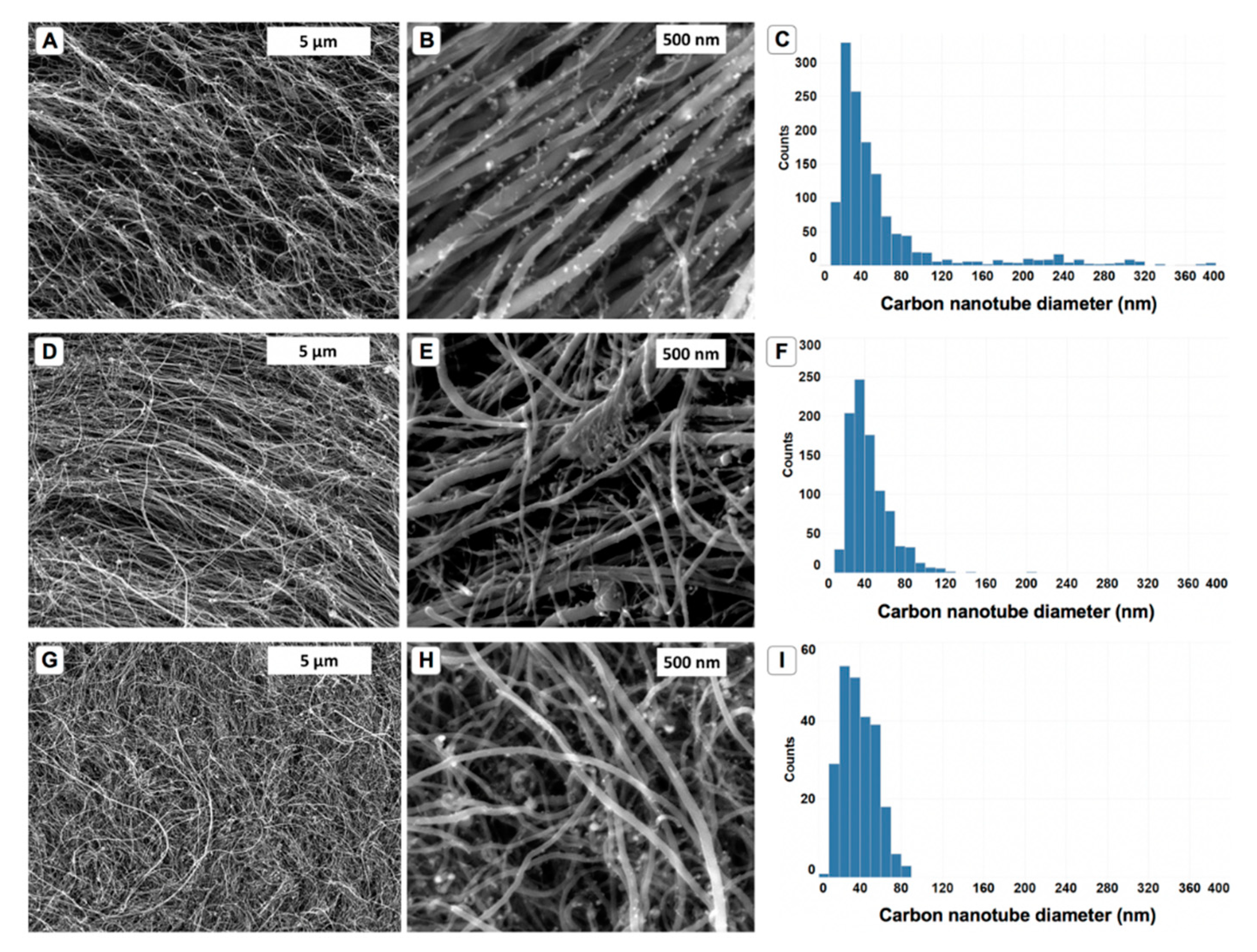
Figure 2.
Representative Raman spectra of carbon nanotubes samples created for this study.

Figure 3.
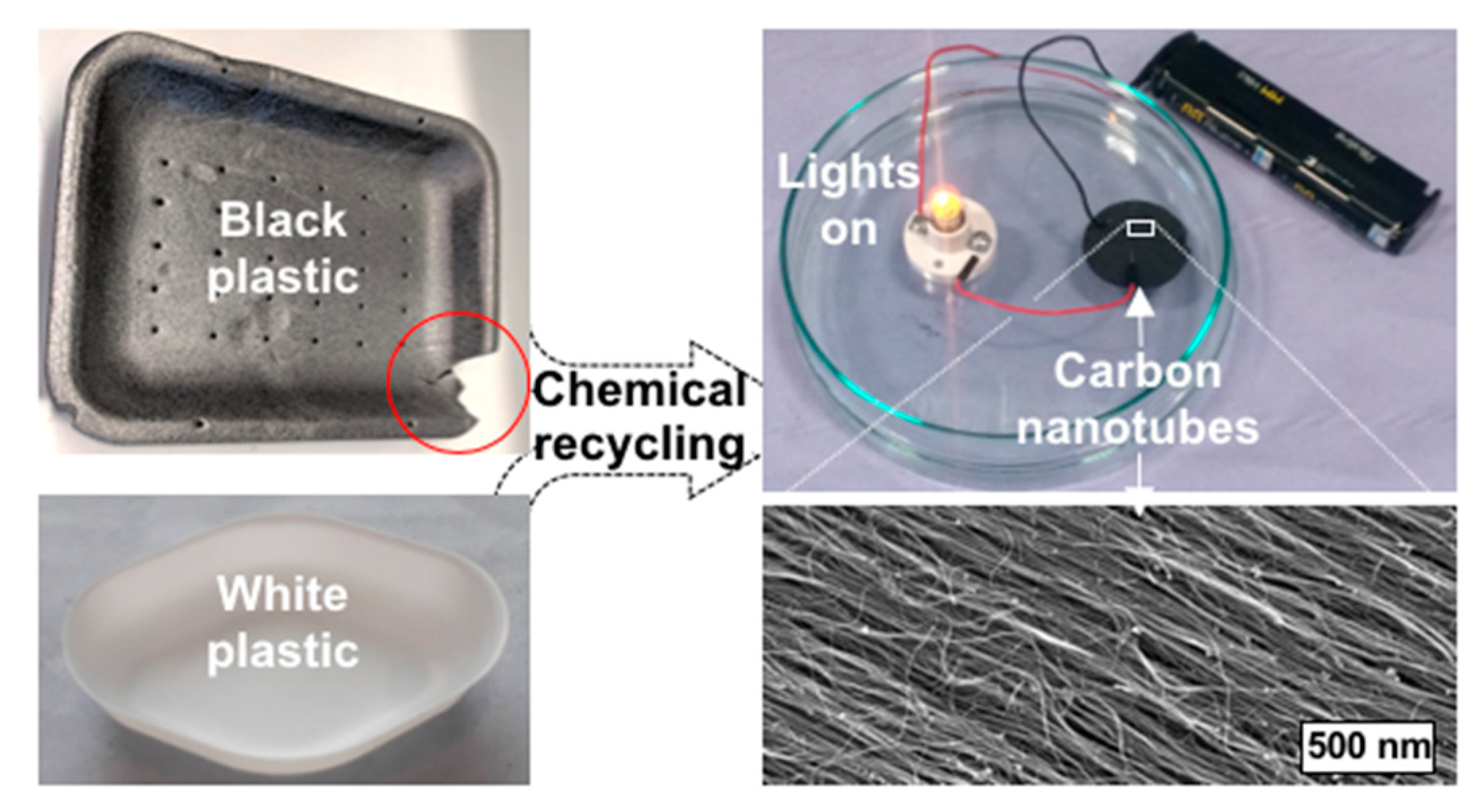
In this figure, we can see the concept of using plastic materials in a chemical recycling process in order to form thin films of carbon nanotubes. The bottom corner of the black plastic container (red circle) shows the parts that were used in this study. The CNT films can close an electrical circuit causing a light to turn on.
Figure 3.
In this figure, we can see the concept of using plastic materials in a chemical recycling process in order to form thin films of carbon nanotubes. The bottom corner of the black plastic container (red circle) shows the parts that were used in this study. The CNT films can close an electrical circuit causing a light to turn on.


Table 1.
Table showing the representative Raman G/D ratio for each sample measured in this study.
| Samples | Max | Min | Median |
|---|---|---|---|
| Control | 2.0 | 1.6 | 1.8 |
| White plastic | 2.4 | 1.1 | 2.2 |
| Black plastic | 2.5 | 1.5 | 2.1 |
© 2019 by the authors. Licensee MDPI, Basel, Switzerland. This article is an open access article distributed under the terms and conditions of the Creative Commons Attribution (CC BY) license (http://creativecommons.org/licenses/by/4.0/).
Share and Cite
MDPI and ACS Style
Hedayati, A.; Barnett, C.J.; Swan, G.; Orbaek White, A. Chemical Recycling of Consumer-Grade Black Plastic into Electrically Conductive Carbon Nanotubes. C 2019, 5, 32. https://0-doi-org.brum.beds.ac.uk/10.3390/c5020032
AMA Style
Hedayati A, Barnett CJ, Swan G, Orbaek White A. Chemical Recycling of Consumer-Grade Black Plastic into Electrically Conductive Carbon Nanotubes. C. 2019; 5(2):32. https://0-doi-org.brum.beds.ac.uk/10.3390/c5020032
Chicago/Turabian StyleHedayati, Ali, Chris J Barnett, Gemma Swan, and Alvin Orbaek White. 2019. "Chemical Recycling of Consumer-Grade Black Plastic into Electrically Conductive Carbon Nanotubes" C 5, no. 2: 32. https://0-doi-org.brum.beds.ac.uk/10.3390/c5020032
Note that from the first issue of 2016, this journal uses article numbers instead of page numbers. See further details here.