A Novel Mesoporous Carbon as Potential Conductive Additive for a Li-Ion Battery Cathode


Grupo Ciencia de los Materiales, Sede de Investigación Universitaria (SIU), Universidad de Antioquia, Calle 62 No. 52-59, Lab 310, Medellín 05001, Colombia
*
Author to whom correspondence should be addressed.
C 2019, 5(4), 81; https://0-doi-org.brum.beds.ac.uk/10.3390/c5040081
Submission received: 23 October 2019
/
Revised: 13 November 2019
/
Accepted: 18 November 2019
/
Published: 3 December 2019
(This article belongs to the Special Issue Porous Carbon: Synthesis, Modification and Applications)
Abstract
:A new mesoporous carbon (MC) is obtained from pyrolysis of resorcinol/formaldehyde resin, polymerized in the presence of tetraethoxysilane and Pluronic F108, followed by pyrolysis at 800 °C and silica removal. The reaction mixture in a molar ratio of 1F108/60resorcinol/292 formaldehyde/16900 H2O/50 tetraethoxysilane heated at 67 °C produces MC nanoparticles (200 nm average size) exhibiting 3D bimodal mesopores (3.9 and 8.2 nm), 1198 m2/g surface area, 1.8 cm3/g pore volume, and important graphitic character for use as a conductive material. Composites LiFePO4/carbon prepared with MC or commercial Super P, by the slurry method, were tested as coin Li-ion battery (LiB) cathodes. Super P (40 nm average particle size) exhibits better graphitic character, but lower porosity than MC. LiFePO4/MC shows better specific capacity (161 mAhg−1) than LiFePO4/Super P (126 mAhg−1), with a retention capacity (RC) after cycling at C/10 of 81%. Both composites with MC and Super P show well-distributed particles. According to impedance analysis, MC mesoporosity improves the charge transfer kinetics (CTK) more than Super P, producing a cathode with higher efficiency, although lithium ions’ diffusion decreases because larger MC particles form longer diffusion paths. Owing to the good specific capacity of the LiB cathode prepared with MC, research looking into improving its retention capacity should be a focus.
1. Introduction
The lithium insertion compounds, with an olivine structure, are considered as potential positive electrode materials of large-scale lithium-ion rechargeable batteries (LIBs) for electric vehicles because of their high operative voltage and energy density. Among the olivine compounds, LiFePO4 as a cathode material in lithium ion batteries is important because it exhibits low toxicity and is obtained at a relatively low cost. Additionally, it has a high lithium intercalation voltage of 3.4 V, which is compatible with most existing organic electrolytes; a high theoretical capacity of 170 mAhg−1; and safety when compared with cobalt oxide-based olivine materials for large-scale applications [1]. However, LiFePO4, when cycled, has a practical capacity much lower than the theoretical capacity. This limitation for commercial applications has mainly been attributed to the low intrinsic electronic conductivity 10−11 Scm−1 (compared with 10−3 Scm−1 for LiCoO2) and low Li+ diffusion coefficient through the LiFePO4/FePO4 interface [2,3]. To overcome these drawbacks and to improve the electrochemical performance of LiFePO4, many studies have been conducted involving reduction of LiFePO4 particle-size, metal ions doping, carbon coating, use of conductive additives, and synthesis of LiFePO4–porous carbon composites [1,4,5]. Decreasing the LiFePO4 particle size leads to shortening of the Li+ diffusion path, but increases the surface area; therefore, the amount of binder needed to glue the LiFePO4 particles will increase, leading to a decrease in capacity [6,7]. Metal doping expands the Li+ diffusion channel, increasing the output voltage of an LiFePO4-based battery [8,9].
The carbon coating is used to increase the electron migration rate during the battery processes [10,11,12]. Dispersing conductive additives as metal or carbon black powders with LiFePO4 nanoparticles improve the contact between LiFePO4 and electrolyte, and thus the electronic and ionic conductivity [13,14,15].
Besides carbon coating or the use of conductive additives, LiFePO4/porous carbon composites as cathode materials have shown improvements in the lithium storage kinetics [16,17,18,19]. With nanostructured LiFePO4/C nanocomposites, it is possible to reach extremely high-power densities [20,21,22]. Ni et al., synthesized carbon-coated LiFePO4–porous carbon as a cathode for a lithium ion battery [23]. Wang et al., prepared a LiFePO4/CMK-3 composite as a cathode, where CMK-3 is highly conductive carbon with mesoporous channels and interconnected pores networks, prepared by the nanocasting method. LiFePO4 particles are embedded in the mesoporous channels in the carbon matrix. At low current discharge rates, LiFePO4/CMK-3 delivers a capacity similar to the theoretical one with high capacity retention. At high current rates, the cell also presents satisfactory specific capacity with excellent cyclability [24]. Yu et al., synthesized LiFePO4/carbon mesoporous nanocomposites by a facile “all in one” hydrothermal method, with excellent capacity retention [25]. Cheng et al., synthesized mesoporous LiFePO4/C composites using bimodal mesoporous carbon (BMC). The pore structure of BMC affords good particle connectivity for LiFePO4, and also allows a rigid nano-confinement that controls the particle size. The good performance rate of these electrodes can mainly be attributed to the small particle size and good dispersion of LiFePO4, which improves the ion and electron diffusion [26]. Sun et al., synthesized LiFePO4–carbon mesoporous nanocomposites by a one-pot soft-template method with a high surface area, defined pore size, and homogenous distribution of small particles of LiFePO4. These nanocomposites exhibited a high current rate [27].
The LiFePO4–porous carbon composites, prepared preserving the carbon porosity by mixing of the active LiFePO4 particles with porous carbon particles, could give an improved effect upon cathode performance. In this work, we developed a new method for the synthesis of mesoporous carbon as an additive for LiFePO4. The method is based on the polymerization of resorcinol–formaldehyde in alkaline aqueous medium in the presence of the template system constituted by the triblock copolymer surfactant F108 and tetraethoxysilane (TEOS), following a procedure similar to the one reported using a phenol–formaldehyde resin [28]. The effect of the porous characteristics and graphitic character of the synthesized carbon on the performance of a coin LIB with an LiFePO4 /carbon cathode is studied.
2. Materials and Methods
2.1. Chemicals
The copolymer triblock surfactant PEO132PPO50PEO132, (F108), MW = 14600, resorcinol (99%), tetraetoxisilane (TEOS, 98%) and NaOH were provided by Merck (Darmstadt, Germany). Formaldehyde solution (37%) and ultrapure water (18.2 MScm−1) were used in all experiments. N-methilpyrrolidone (NMP) and polividen flouride (PVDF) were obtained from Sigma-Aldrich. LiFePO4 (lithium iron (II) phosphate) with bimodal particle size distribution (0.2–20 µm, centered at 1 and 6 µm) was purchased from MTI corporation (Richmond, CA, USA, Reference Powder for Li-ion Battery Cathode, 150 g/bottle-EQ-Lib-LFPO-S21). Super P carbon (40 nm average particle size), the aluminum foils, coin cell materials, the electrolyte (a mixture of ethylene carbonate and methyl-ethyl carbonate (1:1 in volume) with 1 M LiFP6), and the lithium foil were purchased from MTI corporation (Richmond, CA, USA).
2.2. Synthesis of Mesoporous Carbon (MC)
F108 was dissolved in 30 mL 0.05 M NaOH solution (H2O/F108 molar ratio of 16,900). To this solution, TEOS was added, under stirring, to obtain a TEOS/F108 molar ratio of 50. The solution was kept under magnetic stirring (200–300 rpm) in an oil bath at 45 °C for 18 h. Then, resorcinol and formaldehyde were added to obtain a solution with a molar ratio of 50TEOS/1surfactant/60 resorcinol/292formaldehyde. The reaction mixture was heated under stirring at 45 °C for 1 h and then at 67 °C for 48 h. The solid was recovered by centrifugation, washed with water, and dried at room temperature overnight. The as-synthesized sample was subjected to pyrolysis at 800 °C for 3 h to obtain the composite carbon–silica. The pyrolysis was carried out in a horizontal tubular furnace under an N2 flow rate of 100 cm3/min and a heating rate of 2 °C/min. The composite was treated with 9% HF solution over three days to obtain the MC.
2.3. Preparation of Composites LiFePO4/MC and LiFEPO4/Super P
For the electrode preparation, 1.5 mL of NMP and 50 mg of PVDF were mixed and stirred to form a transparent solution. To this solution, 50 mg of carbon (Super P or MC) was added and stirred for one hour, after which 450 mg of LiFePO4 was added and the mixture was stirred for 24 h in a closed container. Finally, the slurry was spread over an aluminum foil with an automatic coating machine (msk-afa-III, MTI Corporation, Richmond, CA, USA), forming a 10 µm thick coating layer. The electrode was dried at 40 °C for 2 h and then at 60 °C for 2 h, and finally left under vacuum for 24 h at 120 °C, according to procedure previously reported [29]. The dried coated foil was pressed three times using a MSK-HRP 4 hot rolling press at 90 °C (MTI). The electrodes with 1.8 cm diameter were cut using an EL-cut (EL-CELL) and kept under humidity- and oxygen-free conditions.
2.4. Physical and Chemical Characterization of Carbons and Composites
Nitrogen adsorption/desorption was performed in an ASAP 2020 Micromeritics. The samples were pretreated at 250 °C over 12 h under vacuum. The BET model was used to determine the specific surface area and the total pore volume was obtained at 0.99 P/Po. The mesoporous volume and pore size distribution were obtained using the Barret–Johner–Halendar (BJH) model. The microporous volume was determined by the t-plot method using a non-microporous reference carbon [30].
Small-angle X-ray scattering (SAXS) was performed in the 1 < 2θ < 5 range in a Philips PW1130 equipment using Cu Kα radiation.
By transmission electron microscopy (TEM, Tecnai G2 F20), the particle morphology and pore features were obtained. The samples were dispersed in ethanol by sonication for 2 h and then dropped in a copper grid. Structural characterization was carried out by RAMAN (Horiba LabRAM HR, wavelength 532 nm) and X-ray diffraction patterns in the 5 < 2θ < 70 range (Philips PW1130), using Cu Kα radiation.
The characterization of the composites was done by XRD (Philips PW1130) in order to confirm the presence of the olivine structure of LiFePO4 and by EDX (SEM, JEOL JSM-6490) to evaluate the carbon and LiFePO4 particles’ dispersion.
To determine the decomposition temperature, thermal gravimetric analysis (TGA) of the carbons, under 40 mL/min air flow in a temperature range 25–800 °C with a heating rate of 10 °C/min, was done in a TGA-Q500 instrument.
2.5. Electrochemical Characterization of the Composites LiFePO4/MC and LiFePO4/Super P
Coin cells were assembled in a glove box under moisture and oxygen levels lower than 0.5 ppm. The coin cells were assembled using lithium foil as the anode, the nanocomposite material LiFePO4/MC as the cathode, and ethyl carbonate and di-methyl carbonate 1:1 (v/v)/1 M LiPF6 as the electrolyte. For comparison purposes, another coin cell was prepared in which the cathodic material was replaced by LiFePO4/Super P, following the same procedure. Charge/discharge experiments were performed at 0.1 C from 2.5 V to 4.2 V, where C is the theoretical capacity of LiFePO4 (170 mAhg−1). Additionally, electrochemical impedance spectroscopy (EIS, potentiostat/galvanostat VMP3) was performed on the coin cells before and after the charge/discharge cycles for the nanocomposite electrodes, with 10 mV perturbation applied in the range of frequencies from 1 MHz up to 100 mHz at open circuit conditions.
3. Results and Discussion
3.1. Porous and Morphological Characteristics of Carbon Samples
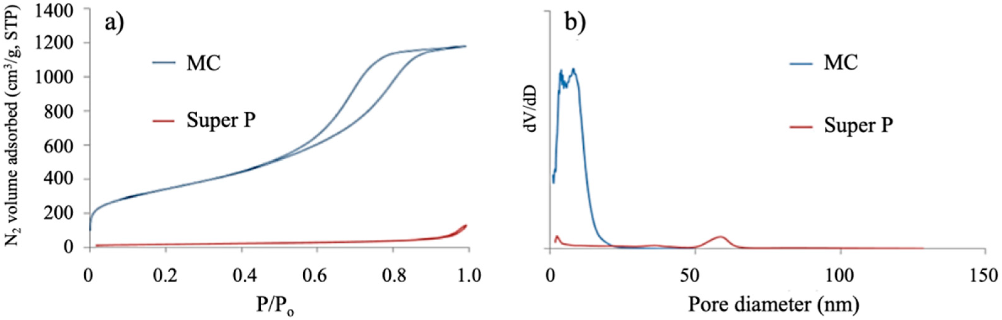
Figure 1a,b present the nitrogen adsorption/desorption isotherms and the BJH pore size distribution of MC and Super P, respectively, and Table 1 presents their porous characteristics. MC exhibits type IV isotherms with H1 hysteresis loop corresponding to materials with cylindrical mesopores and Super P exhibits poorer porosity with type II isotherms typical of macroporous materials (Figure 1a).
As seen in Table 1, MC exhibits a high BET surface area, and high mesoporous volume with pore sizes around 3.9 and 8.2 nm (Figure 1b). Super P exhibits a smaller BET surface area and pore volume, represented mainly by macroporous volume corresponding to pores around 59 nm (Figure 1b).
Origin of the Bimodal Porosity of MC
At 67 °C, the resorcinol/formaldehyde polymerization, in the reaction medium for MC synthesis, causes a synergistic effect with siliceous species in the obtaining of a carbon–silica mesoporous composite, forming intercrossing nets of mesoporous silica and mesoporous carbon, according to previous synthesis with phenol as the carbon precursor instead of resorcinol [28]. After pyrolysis of the composite and silica removal, mesoporous carbon nanoparticles with an average size of around 200 nm and bimodal mesoporosity are obtained. The pores around 8.2 nm and 3.9 nm are attributable to F108 micelles covered mainly by silica and mainly by resol species, respectively, during synthesis. The SAXS spectrum for MC failed to show pore organization.
3.2. Structural Characterization
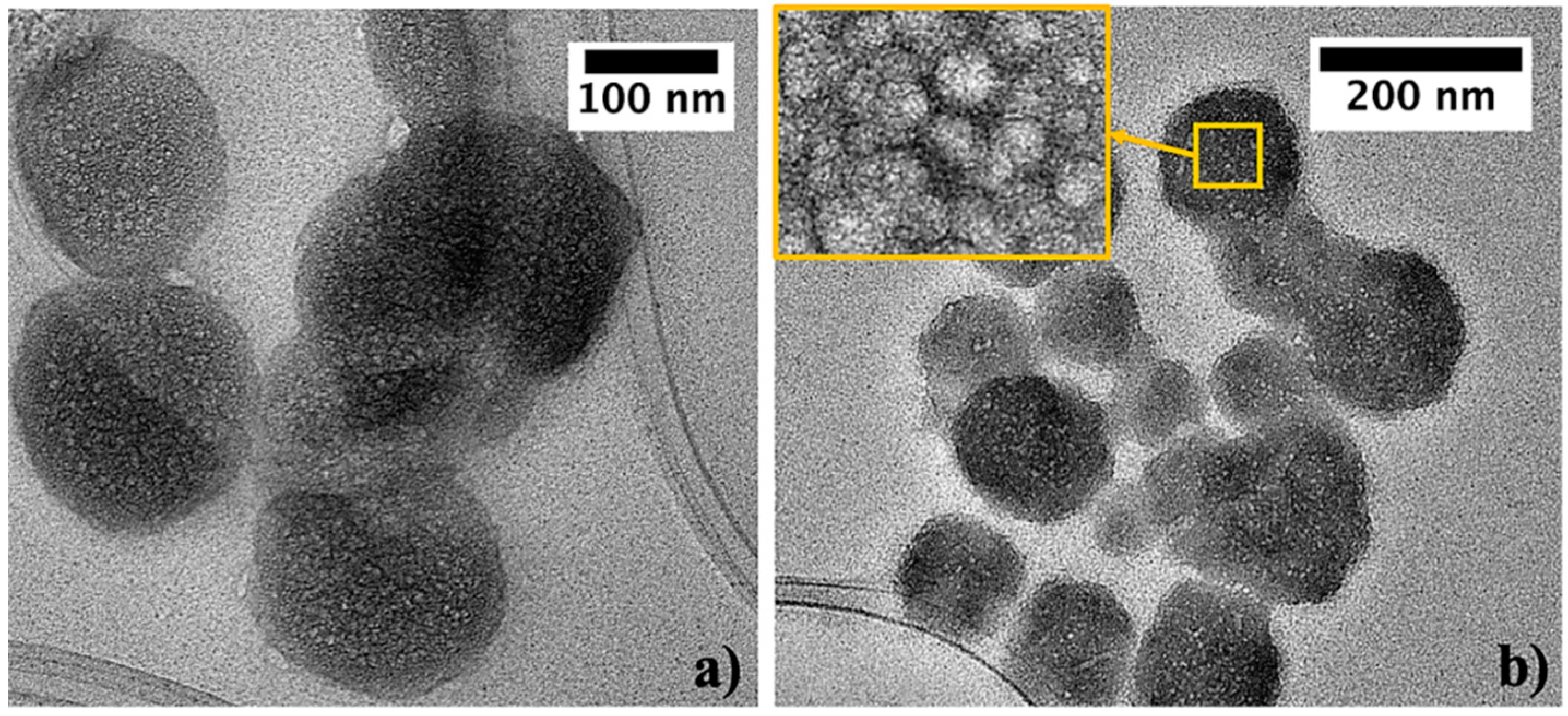
In the TEM micrographs (Figure 2), the carbon MC looks composed of primary spheroidal porous nanoparticles with sizes between 50 and 220 nm, with an average value of 200 nm. According to MTI materials supplier, the graphitic carbon Super P is composed by nanoparticles with average size of 40 nm. The 3D bimodal porosity of MC nanoparticles (pores around 3.9 and 8.2 nm, measured by N2 adsorption/desorption) is seen in the enlarged TEM image of the surface of one of the particles (upper left inset in Figure 2b).
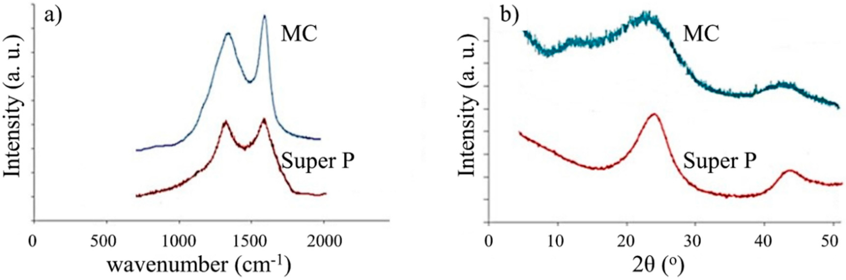
Figure 3 presents the RAMAN spectra and XRD patterns of MC and Super P. The Raman spectra of MC and Super P, in Figure 3a, show the signals corresponding to the vibrational modes D (A1g) and G (E2g), at 1330 and 1596 cm−1, respectively. The D signal is associated with defects on the graphitic structure and the G signal is associated with graphitic vibrations. The intensity ratio ID/IG, in peak areas, defines the amount of defects and thus the degree of graphitization of a carbon, where a higher ratio indicates a higher number of defects. The carbon conductivity depends on its graphitization degree. The ID/IG, in peak area ratios, for MC and Super P are shown in Table 2. The ID/IG ratio for MC, although lower that than for Super P, can be considered as a value that indicates a good graphitic character.
The XRD patterns of MC and Super P (Figure 3b) show the peaks (002) at 2θ~24° and (100) at 2θ~42° corresponding to graphite. The peak at 2θ~16° for MC is assigned to aliphatic side chains, attached to the edge of the graphite crystallites [31].
Table 2 presents the crystallographic parameters estimated from Raman data and the XRD patterns, as shown below, and the decomposition temperatures obtained from the TGA analysis.
From the Raman spectrum, the graphitic domain size La was evaluated using the following equation: La (nm) = (2.4 × 10⁻¹⁰)λ4(ID/IG)−1, with λ = 532 nm [32]. The (002) peak for MC and Super P defines the spacing of aromatic ring layers in their crystallites. The width of this peak, for the two carbons, is rather broad, indicating that they exhibit a random layer lattice structure occasioned by defects on the graphitic layers. From the diffraction peak in the plane (002) at ~2θ = 24°, the graphitic interlayer spacing d002, the stacking height Lc, and the number of graphene stacking layers n were determined. The interlayer spacing d002 was calculated from Bragg’s Law. Lc was determined using the following equation: Lc = 0.9 λ/β002 cos θ002, with β002 = half width of 002 peak in radians and the number of grapheme stacking layers n as LC/d002 [33].
Super P exhibits a higher decomposition temperature and larger graphitic domains, as well as larger Lc and n values and a smaller d002 than MC (Table 2), which indicates its better graphitic nature. Nevertheless, the moderated graphitic nature exhibited by MC qualifies it as a potential conductive additive.
3.3. Physical and Chemical Characterization of LiFePO4/MC and LiFePO4/Super P
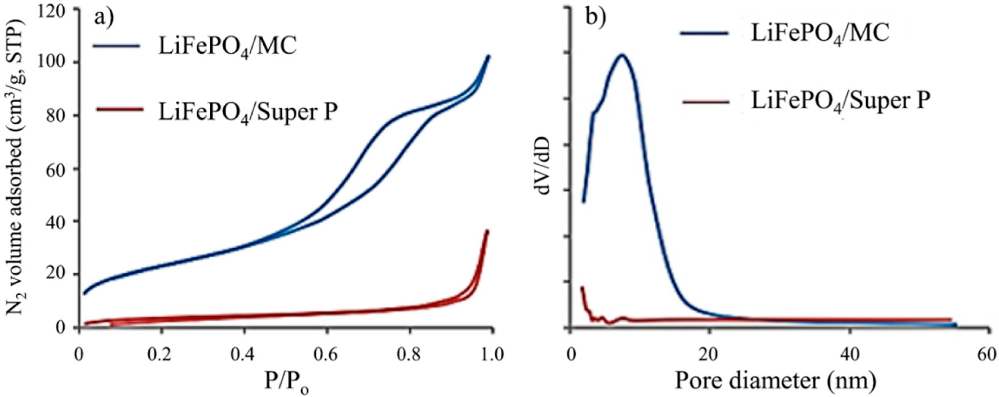
Figure 4 shows the nitrogen adsorption/desorption isotherms and pore size distributions of the prepared electrode materials, and Table 3 shows their porous characteristics.
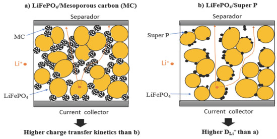
By comparison with the carbons, the composites on average exhibit an increase in macroporous volume resulting from interparticle porosity generated during formation of the composite, but a decrease in mesoporous volume, which is in agreement with the low percent of carbon in the composite. Table 3 shows that LiFePO4/MC is the composite with the better mesoporous characteristics (Figure 4a,b), with a mesoporosity derived mainly by the carbon particles themselves, which is not hindered by the formation of the composite, besides that of the meso-macro porous textural interparticle porosity resulting from the formation of the composite. As a lithium ion battery cathode, LiFePO4/MC, when compared with LiFePO4/Super P, thanks to its intraparticle 3D MC porosity, can improve the charge transfer kinetics of the active material with which it is in contact, decreasing the charge transfer resistance and increasing the cell voltage [34]. Li et al., synthetized a mesoporous LiFePO4/C nanocomposite, using bimodal mesoporous carbon as continuous conductive networks, which promises high utilization of the active material and offers rapid ion and electron transport. A LIB with this composite as the cathode exhibits capacities of 120 mAhg−1 and 42 mAhg−1 at 0.1 C and 10 C current rates, respectively [26].
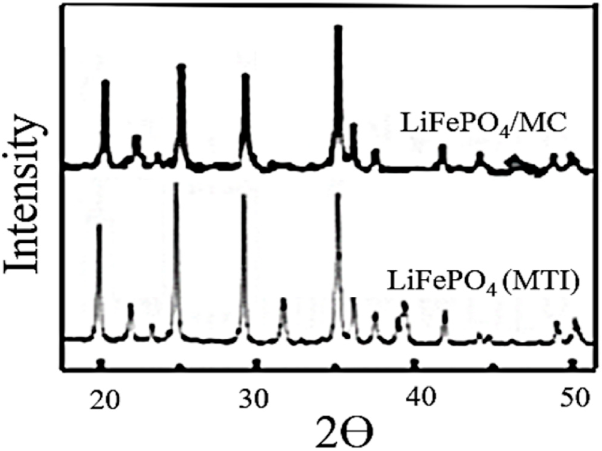
The presence of highly crystalline LiFePO4 in the LiFePO4/MC composite is confirmed by comparing its XRD pattern with that of the standard LiFePO4 from MTI (Figure 5).
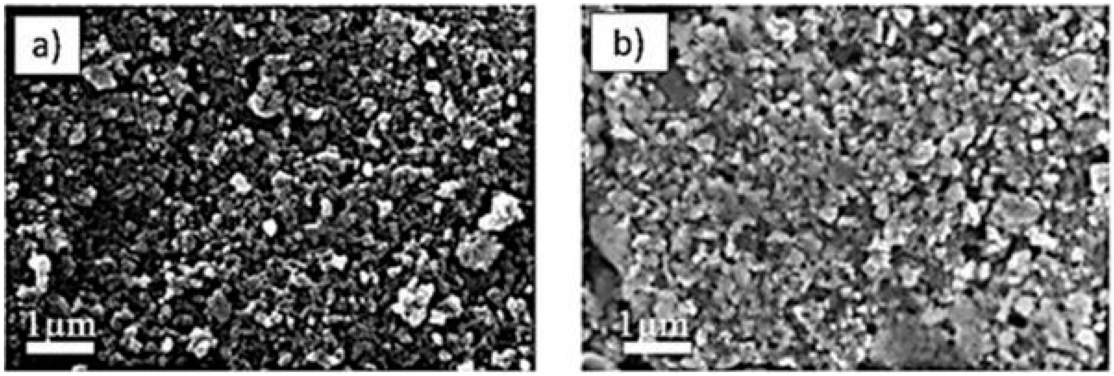
SEM images of LiFePO4/MC and LiFePO4/Super P composites are presented in Figure 6a,b, respectively. High dispersion of both carbon and LiFePO4 (white and light grey particles) in the surface of the composites prepared with Super P or MC is observed.
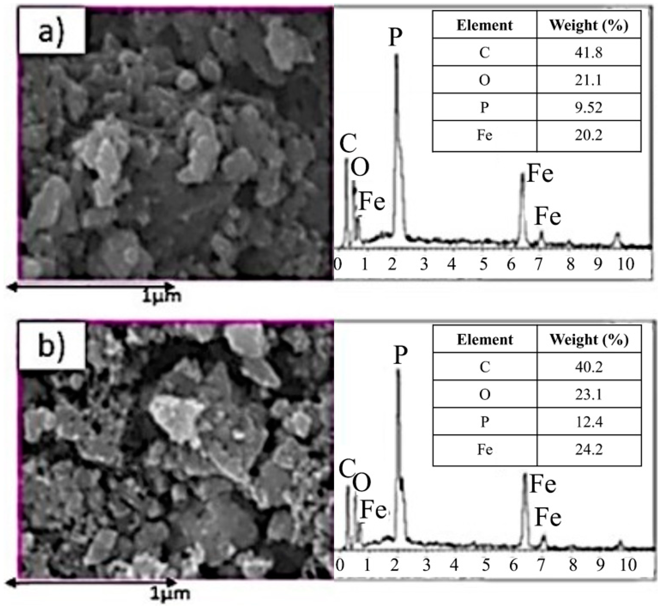
Figure 7 shows EDX mappings of the composites, where the carbon and LiFePO4 particles in the LiFePO4/C composites, along a representative area, show a good dispersion. As can be seen, for LiFePO4/MC and LiFePO4/Super P, the carbon is uniformly distributed across the analyzed area in a relative amount of 41.8 wt% and 40.2 wt%, respectively, which can include, besides initial carbon particles, binder material involved in the electrode preparation.
The dispersion of conductive carbon in the composites LiFePO4/MC and LiFePO4/Super P predicts the formation of a well interconnected conductive network, developed on particle–particle contact of the LiFePO4 active material, which is the first condition for having good electrochemical performance of a LiFePO4 cathode. The interparticle textural volume for the two composites with the same weight composition is higher for LiFePO4/Super P than for LiFePO4/MC, because, owing to the porous nature of MC and its larger particle diameter, more volume in the composite is occupied for this carbon than for Super P, and less interparticle volume remains. The larger interparticle volume allows the formation of more straightforward Li diffusion paths in the case of LiFePO4/Super P, and thus better lithium diffusion through the electrode.
3.4. Electrochemical Performance of Lithium-Ion Battery
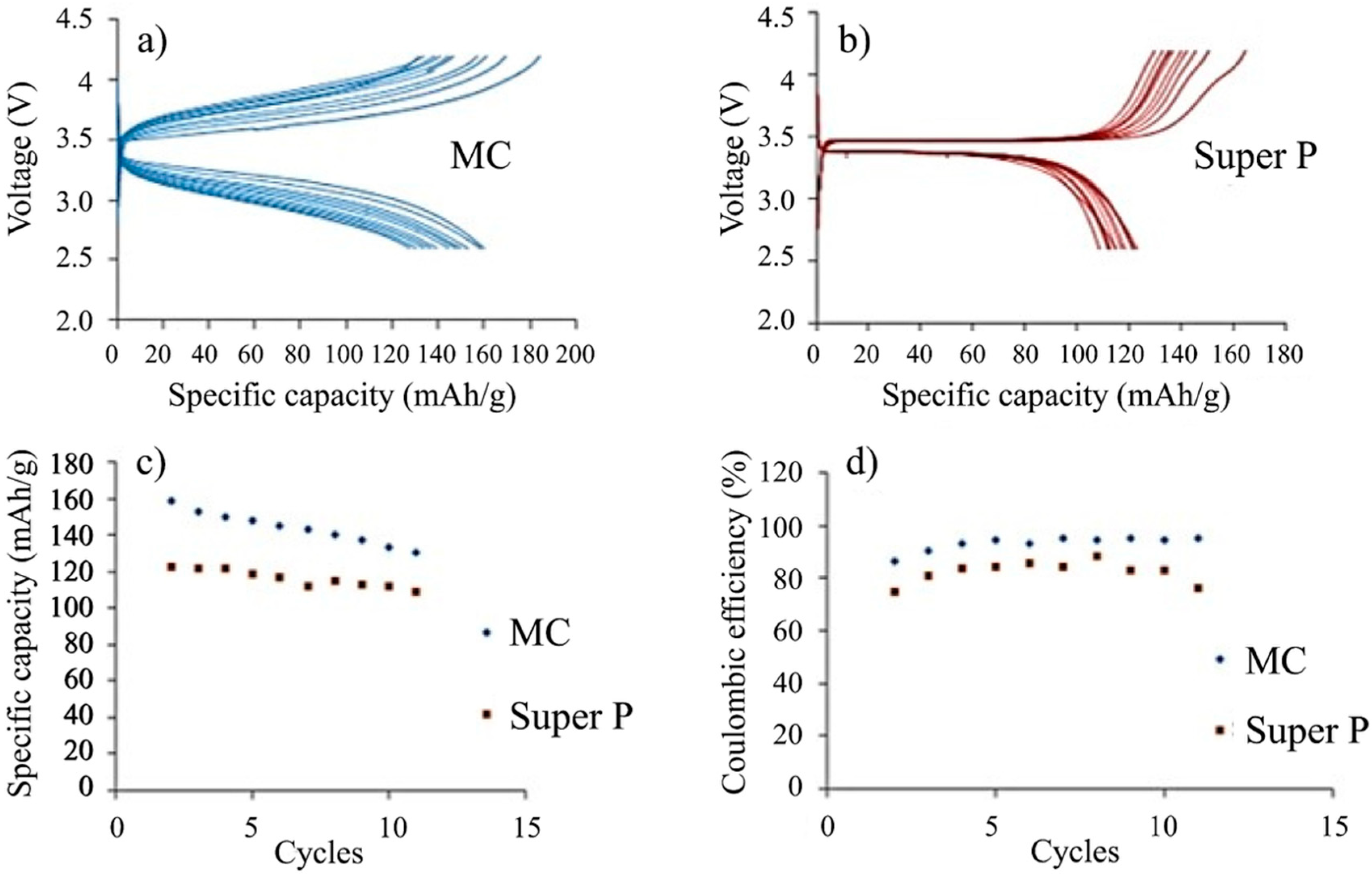
Figure 8 depicts the specific capacity versus voltage curves obtained in the charge/discharge processes at C/10 current rate, using the nanocomposites LiFePO4/MC and LiFePO4/Super P.
LiFePO4/MC presents a specific capacity of 161 mAhg−1 in the first cycle, which is close to the theoretical capacity of LiFePO4 (170 mAhg−1), and maintains 81.1% of this capacity after 11 cycles at 0.1 C with good coulombic efficiency (Figure 8a,c,d). After the third cycle, the coulombic efficiency in LiFePO4/MC increases to the range of 93–96%, and reaches a value above 96% for the 11 cycle (Figure 8d), demonstrating the outstanding reversibility of the electrode.
LiFePO4/Super P presents a specific capacity of 126 mAhg–1 in the first cycle, which is lower than that of LiFePO4/MC, and maintains 87.0% of this capacity after 11 cycles at 0.1 C with lower coulombic efficiency (Figure 8b–d). After the third cycle, the coulombic efficiency in LiFePO4/Super P increases to the range of 75–85%, and then decreases to 78% for the 11 cycle.
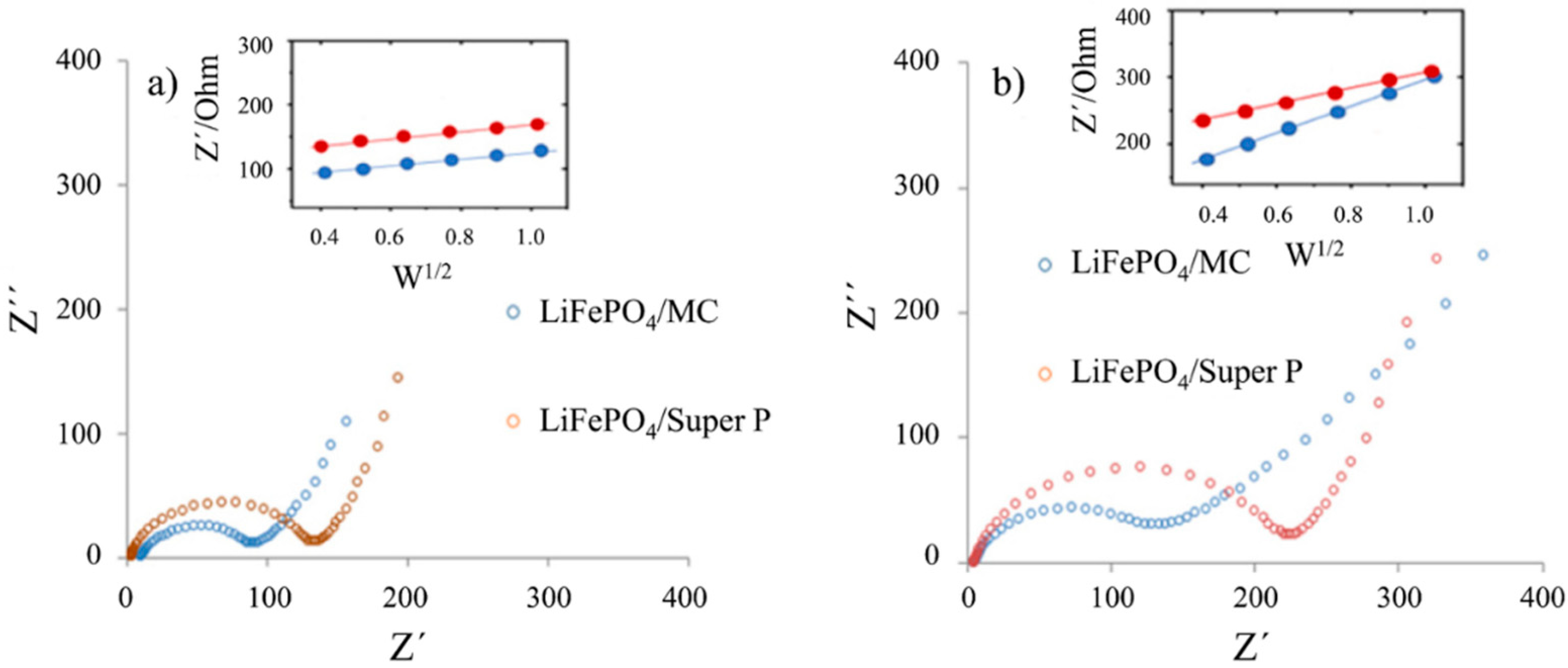
The behavior of the composite electrodes can be also analyzed in the Nyquist diagrams obtained by EIS before and after 11 charge/discharge cycles (Figure 9). The semicircle associated with the charge transfer resistance and double layer capacitance, observed at medium frequencies, followed by a straight line at lower frequencies associated to lithium diffusion, shows differences between the two samples [35,36,37]. The nanocomposite material LiFePO4/MC presents lower charge transfer resistance compared with LiFePO4/Super P before and after the charge/discharge cycles. Although Super P presents higher conductivity than MC owing to its higher graphitization degree (Figure 3), the specific nature of MC such as the porosity and graphene layer to layer distance affects the charge transfer resistance. The insets in Figure 9 show the relation between the real components of the impedance and the inverse of the square root of the frequency.
The values for the lithium diffusion coefficients (DLi+) in the composites, before and after cycling, are presented in Table 4.
Before cycling, DLi+ for LiFePO4/MC is lower than for LiFePO4/Super P owing to the formation of less interparticle porosity in the case of LiFePO4/MC, as discussed above. After 11 charge/discharge cycles, the charge transfer resistance for the two composites increased and the lithium diffusion decreased, indicating a decrease in capacity during cycling. This decrease can be attributed to a deterioration of the composites, for instance, by loss of adherence to the PVDF binder; occasioning aggregation of particles; and a decrease in connectivity between LiFePO4 and carbon additives, and thus in retention capacity. The retention capacity can be increased by improving the slurry preparation of the electrode, for instance, by optimizing their composition and the temperature at which the solvent NMP is evaporated.
4. Conclusions
A new bimodal mesoporous carbon (MC) is obtained from pyrolysis at 800 °C of resol (resorcinol–formaldehyde resin) polymerized at 67 °C, in the presence of tetraethoxysilane (TEOS) and the triblock copolymer Pluronic F108 (PEO132PPO50PEO132) in alkaline medium with the composition of the following molar ratio: 1F108/60 resorcinol/292 formaldehyde/16,900 H2O/50 TEOS.
MC nanoparticles with an average size around 200 nm, exhibit, by N2 adsorption, non-ordered 3D bimodal mesopores of 3.9 and 8.2 nm in size and high superficial area (1198 m2/g) and pore volume (1.8 cm3/g), and an important graphitic character according to RAMAN and XRD information, which qualifies them as good conductive particles.
The polymerization of resorcinol/formaldehyde at 67 °C, in the MC synthesis, causes a synergistic effect with siliceous species in the obtaining of mesoporous composites carbon–silica, exhibiting intercrossing nets of mesoporous silica and mesoporous carbon. After silica removal, the carbon shows pores around 8.2 nm and 3.9 nm formed by micelles covered mainly by silica species and micelles covered mainly by resol species during synthesis, respectively.
MC as a conductive additive allows the formation of a composite with well-distributed carbon and LiFePO4 particles, as carbon Super P does. According to the impedance results, the 3D mesoporous contribution of MC improves the charge transfer kinetics considerably compared with Super P, which has a higher graphitic character. On the other hand, the diffusion of lithium ions through the LiFePO4/MC cathode, although high, is not better than that obtained through the LiFePO4/Super P cathode, which indicates that more difficult lithium ion transport occurs in LiFePO4/MC, owing to the MC larger primary particle size, which brings the formation of longer diffusion lithium paths. The higher efficiency of the LiFePO4/MC cathode than LiFePO4/Super P results from the increase in the charge transfer kinetics owing to the high intraparticle mesoporosity of MC. The lower retention capacity, during cycling, for LiFePO4/MC than for LiFePO4/Super P can be attributed to a larger decrease in Li diffusion occasioned by a higher loss in interparticle volume owing to the larger MC particle size than Super P. Improving the slurry preparation of the electrode, for instance, optimizing their composition and the temperature at which the NMP solvent is evaporated, should be a focus in order to enhance the MC cathode efficiency for coin LIBs.
Author Contributions
Conceptualization, V.V., B.L., R.P., and L.S.; Formal analysis, V.V., B.L., R.P., and L.S.; Investigation, V.V., B.L., R.P., and L.S.; Methodology, V.V., B.L., and L.S.; Writing—original draft, V.V. and L.S.; Writing—review & editing, V.V., B.L., R.P., and L.S.
Funding
This research received no external funding.
Acknowledgments
The authors thank the laboratory of electrochemistry of UAM-I (México) for allowing the experimental facilities to make the electrochemical experiments. Victor Velez thanks COLCIENCIAS for the fellowship given by the CONVOCATORIA DOCTORADOS NACIONALES 727.
Conflicts of Interest
The authors declare no conflict of interest.
References
- Deng, S.; Wang, H.; Liu, H.; Liu, J.; Yan, H. Research Progress in Improving the Rate Performance of LiFePO4 Cathode Materials. Nano-Micro Lett. 2014, 6, 209–226. [Google Scholar] [CrossRef]
- Zhang, Y.; Huo, Q.Y.; Du, P.P.; Wang, L.Z.; Zhang, A.Q.; Song, Y.H.; Lv, Y.; Li, G.Y. Advances in new cathode material LiFePO4 for lithium-ion batteries. Synth. Met. 2012, 162, 1315–1326. [Google Scholar] [CrossRef]
- Padhi, A.K.; Nanjundaswamy, K.S.; Goodenough, J.B. Phospho-olivines as Positive-Electrode Materials for Rechargeable Lithium Batteries. Electrochem. Sci. Tech. 1997, 144, 1188–1194. [Google Scholar] [CrossRef]
- Wang, Z.-H.; Yuan, L.-X.; Wu, M.; Sun, D.; Huang, Y.-H. Effects of Na+ and Cl- co-doping on electrochemical performance in LiFePO4/C. Electrochim. Acta 2011, 56, 8477–8483. [Google Scholar] [CrossRef]
- Lu, Y.; Shi, J.; Guo, Z.; Tong, Q.; Huang, W.; Li, B. Synthesis of LiFe1−xNixPO4/C composites and their electrochemical performance. J. Power Sources 2009, 194, 786–793. [Google Scholar] [CrossRef]
- Saravanan, K.; Balaya, P.; Reddy, M.V.; Chowdari, B.V.R.; Vittal, J.J. Morphology controlled synthesis of LiFePO4/C nanoplates for Li-ion batteries. Energy Environ. Sci. 2010, 3, 457–463. [Google Scholar] [CrossRef]
- Delacourt, C.; Poizot, P.; Levasseur, S.; Masquelier, C. Size Effects on Carbon-Free LiFePO4 Powders. The key to superior energy density. Solid-State Lett. 2006, 9, A352–A355. [Google Scholar] [CrossRef]
- Park, K.S.; Son, J.T.; Chung, H.T.; Kim, S.J.; Lee, C.H.; Kang, K.T.; Kim, H.G. Surface modification by silver coating for improving electrochemical properties of LiFePO4. Solid State Commun. 2004, 129, 311–314. [Google Scholar] [CrossRef]
- Dominko, R.; Bele, M.; Goupil, J.M.; Gaberscek, M.; Hanzel, D.; Arcon, I.; Jamnik, J. Wired porous cathode materials: A novel concept for synthesis of LiFePO4. Chem. Mater. 2007, 19, 2960–2969. [Google Scholar] [CrossRef]
- Wang, Y.G.; Wang, Y.R.; Hosono, E.; Wang, K.X.; Zhou, H.S. The design of a LiFePO4/carbon nanocomposite with a core-shell structure and its synthesis by an in situ polymerization restriction method. Angew. Chem. Int. Ed. 2008, 47, 7461–7465. [Google Scholar] [CrossRef]
- Huang, H.; Yin, S.C.; Nazar, L.F. Approaching theoretical capacity of LiFePO4 at room temperature at high rates. Electrochem. Solid State Lett. 2001, 4, A170–A172. [Google Scholar] [CrossRef]
- Croce, F.; Epifanio, A.D.; Hassoun, J.; Deptula, A.; Olczac, T.; Scrosati, B. A novel concept for the synthesis of an improved LiFePO4 lithium battery cathode. Electrochem. Solid State Lett. 2002, 5, A47–A50. [Google Scholar] [CrossRef] [Green Version]
- Doherty, C.M.; Caruso, R.A.; Smarsly, B.M.; Adelhelm, P.; Drummond, C.J. Hierarchically porous monolithic LiFePO4/carbon composite electrode materials for high power lithium ion batteries. Chem. Mater. 2009, 21, 5300–5306. [Google Scholar] [CrossRef]
- Yu, F.; Zhang, J.-J.; Yang, Y.-F.; Song, G.-Z. Up-scalable synthesis, structure and charge storage properties of porous microspheres of LiFePO4@C nanocomposites. Mater. Chem. 2009, 19, 9121–9125. [Google Scholar] [CrossRef]
- Oh, S.W.; Myung, S.-T.; Bang, H.J.; Yoon, C.S.; Amine, K.; Sun, Y.K. Nanoporous structured LiFePO4 with spherical microscale particles having high volumetric capacity for lithium batteries. Electrochem. Solid-State Lett. 2009, 12, A181–A185. [Google Scholar] [CrossRef]
- Chung, S.Y.; Bloking, J.T.; Chiang, Y.M. Electronically conductive phospho-olivines as lithium storage electrodes. Nat. Mater. 2002, 1, 123–128. [Google Scholar] [CrossRef]
- Wang, G.X.; Bewlay, S.; Yao, J.; Ahn, J.H.; Dou, S.X.; Liu, H.K. Characterization of LiMxFe1 − xPO4 (M = Mg, Zr, Ti) cathode materials prepared by the sol-gel method. Electrochem. Solid State Lett. 2004, 7, A503–A506. [Google Scholar] [CrossRef]
- Sarkar, S.; Mitra, S. Carbon coated submicron sized-LiFePO4: Improved high rate performance lithium battery cathode. Energy Procedia 2014, 54, 718–724. [Google Scholar] [CrossRef] [Green Version]
- Franger, S.; Le Cras, F.; Bourbon, C.; Rouault, H. LiFePO4 synthesis routes for enhanced electrochemical performance. Electrochem. Solid State Lett. 2002, 5, A231–A233. [Google Scholar] [CrossRef]
- Liu, J.; Conry, T.E.; Song, X.; Doeff, M.M.; Richardson, T.J. Nanoporous spherical LiFePO4 for high performance cathodes. Energy Environ. Sci. 2011, 4, 885–888. [Google Scholar] [CrossRef]
- Konarova, M.; Taniguchi, I. Synthesis of carbon-coated LiFePO4 nanoparticles with high rate performance in lithium secondary batteries. J. Power Sour. 2010, 195, 3661–3667. [Google Scholar] [CrossRef]
- Hasegawa, G.; Ishihara, Y.; Kanamori, K.; Miyazaki, K.; Yamada, Y.; Nakanishi, K.; Abe, T. Facile preparation of monolithic LiFePO4/carbon composites with well-defined macropores for a lithium-ion battery. Chem. Mater. 2011, 23, 5208–5216. [Google Scholar] [CrossRef]
- Ni, H.; Liu, J.; Fan, L.-Z. Carbon-coated LiFePO4–porous carbon composites as cathode materials for lithium ion batteries. Nanoscale 2013, 5, 2164–2168. [Google Scholar] [CrossRef]
- Wang, G.; Liu, H.; Liu, J.; Qiao, S.; Lu, G.M.; Munroe, P.; Ahn, H. Mesoporous LiFePO4/C nanocomposite cathode materials for high power lithium ion batteries with superior performance. Adv. Mater. 2010, 22, 4944–4948. [Google Scholar] [CrossRef]
- Yu, L.; Cai, D.; Wang, H.; Titirici, M.-M. Synthesis of microspherical LiFePO4-carbon composites for lithium-ion batteries. Nanomaterials 2013, 3, 443–452. [Google Scholar] [CrossRef] [Green Version]
- Cheng, F.; Li, D.; Lu, A.; Li, W. Controllable synthesis of high loading LiFePO4/C nanocomposites using bimodal mesoporous carbon as support for high power Li-ion battery cathodes. J. Ener. Chem. 2013, 22, 907–913. [Google Scholar] [CrossRef]
- Sun, S.; Ghimbeu, C.M.; Janot, R.; Le Meins, J.-M.; Cassel, A.; Davoisne, C.; Masquelier, C.; Vix-Guterl, C. One-pot synthesis of LiFePO4–carbon mesoporous composites for Li-ion batteries. Microp. Mesop. Mater. 2014, 198, 175–184. [Google Scholar] [CrossRef]
- Santa, C.F.; Jaber, M.; Guth, J.L.; Sierra, L. Synthesis of texturally biphasic mesoporous carbon-silica composites and carbons. Microp. Mesop. Mater. 2013, 173, 53–63. [Google Scholar] [CrossRef]
- Guzmán, G.; Vazquez-Arenas, J.; Ramos-Sánchez, G.; Bautista-Ramírez, M.; González, I. Improved performance of LiFePO4 cathode for Li-ion batteries through percolation studies. Electrochem. Acta 2017, 247, 451–459. [Google Scholar] [CrossRef]
- Rodriguez-Reinoso, F.; Martín-Martinez, J.M.; Prado-Burguete, C.; McEnaney, B. A standard adsorption isotherm for the characterization of activated carbons. J. Phys. Chem. 1987, 91, 515–516. [Google Scholar] [CrossRef]
- Manoj, B.; Kunjomana, A.G. Structural characterization of graphene layers in various Indian coals by X-ray Diffraction. IOP Conf. Ser. Mater. Sci. Eng. 2015, 73, 012096–012100. [Google Scholar] [CrossRef] [Green Version]
- Cançado, L.G.; Takai, K.; Enoki, T. General equation for the determination of the crystallite size La of nanographite by Raman spectroscopy. Appl. Phys. Lett. 2006, 88, 163106–163108. [Google Scholar] [CrossRef]
- Sakintuna, B.; Yürüm, Y.; Çetinkaya, S. Evolution of carbon microstructures during the pyrolysis of Turkish Elbistan lignite in the temperature range 700−1000 °C. Energy Fuels 2004, 18, 883–888. [Google Scholar] [CrossRef]
- Liu, H.; Liu, X.; Li, W.; Guo, X.; Wang, Y.; Wang, G.; Zhao, D. Porous carbon composites for next generation rechargeable lithium batteries. Adv. Energy Mater. 2017, 7, 1614–1683. [Google Scholar] [CrossRef]
- Schmidt, J.P.; Chrobak, T.; Ender, M.; Illig, J.; Klotz, D.; Ivers-Tiffée, E. Studies on LiFePO4 as cathode material using impedance spectroscopy. J. Power Sour. 2011, 196, 5342–5348. [Google Scholar] [CrossRef]
- Illig, J.; Ender, M.; Chrobak, T.; Schmidt, J.P.; Klotz, D.; Ivers-Tiffée, E. Separation of charge transfer and contact resistance in LiFePO4-cathodes by impedance modeling. J. Electrochem. Soc. 2012, 159, A952–A960. [Google Scholar] [CrossRef]
- Chen, Y.W.; Chen, J.S. A study of electrochemical performance of LiFePO4/C composites doped with Na and V. Int. J. Electrochem. Sci. 2012, 7, 8128–8139. [Google Scholar]
Figure 1.
(a) Nitrogen adsorption/desorption isotherms, (b) pore size distributions using Barret–Johner–Halendar (BJH) of the mesoporous carbon (MC) and Super P.
Figure 1.
(a) Nitrogen adsorption/desorption isotherms, (b) pore size distributions using Barret–Johner–Halendar (BJH) of the mesoporous carbon (MC) and Super P.

Figure 2.
(a) and (b): Transmission electron microscopy (TEM) images of MC material. Upper left inset, Figure 2b: enlarged image of the surface of a particle.
Figure 2.
(a) and (b): Transmission electron microscopy (TEM) images of MC material. Upper left inset, Figure 2b: enlarged image of the surface of a particle.

Figure 3.
(a) RAMAN spectra and (b) XRD patterns of the MC and Super P.

Figure 4.
(a) Nitrogen adsorption/desorption isotherms and (b) pore size distributions (BJH) of LiFePO4/MC and LiFePO4/Super P composites.
Figure 4.
(a) Nitrogen adsorption/desorption isotherms and (b) pore size distributions (BJH) of LiFePO4/MC and LiFePO4/Super P composites.

Figure 5.
XRD patterns of LiFePO4/MC and LiFePO4 (MTI) reported by the MTI corporation.

Figure 6.
SEM images of (a) LiFePO4/MC and (b) LiFePO4/Super P.

Figure 7.
EDX mappings of (a) LiFePO4/MC and (b) LiFePO4/Super P.

Figure 8.
Coin cell performance of the composites in a coin cell: (a) LiFePO4/MC; (b) LiFePO4/Super P, charge/discharge curves at C/10 current rate, during 11 cycles; (c) specific capacity; (d) coulombic efficiency.
Figure 8.
Coin cell performance of the composites in a coin cell: (a) LiFePO4/MC; (b) LiFePO4/Super P, charge/discharge curves at C/10 current rate, during 11 cycles; (c) specific capacity; (d) coulombic efficiency.

Figure 9.
Nyquist diagrams of LiFePO4/MC and LiFePO4/Super P as cathodes in a coin cell (a) before and (b) after 11 charge/discharge cycles.
Figure 9.
Nyquist diagrams of LiFePO4/MC and LiFePO4/Super P as cathodes in a coin cell (a) before and (b) after 11 charge/discharge cycles.


Table 1.
Porous characteristics of mesoporous carbon (MC) and Super P.
| Carbon | Vp (cm3/g) | SBET (m2/g) | Dpore (nm) | Amicro (m2/g) | Vmicro (cm3/g) |
|---|---|---|---|---|---|
| MC | 1.82 | 1198 | 3.9; 8.2 | 75 | 0.03 |
| Super P | 0.21 | 57 | 2.1; 59 | - | 0.08 |
Vp: total pore volume measured at 0.99 P/Po; SBET: BET area; Dpore: pore diameter; Vmicro: microporous volume; Amicro: micro area.
Table 2.
Crystallographic parameters and decomposition temperatures of MC and Super P.
| Carbon | ID/IG | La (nm) | Lc (nm) | d002 | n | TD (°C) |
|---|---|---|---|---|---|---|
| MC | 1.40 | 13.3 | 1.36 | 0.38 | 3.56 | 550–680 |
| Super P | 0.84 | 22.9 | 8.12 | 0.35 | 23.20 | 650–750 |
Table 3.
Porous characteristics of the composites.
| Sample | Vp (cm3/g) | SBET (m2/g) | Dpore (nm) | Vmicro (cm3/g) | V2–10 nm (cm3/g) |
|---|---|---|---|---|---|
| LiFePO4/MC | 0.16 | 84 | 3.6, 7.7 | 0.0007 | 0.12 |
| LiFePO4/Super P | 0.06 | 14 | - | 0.0001 | 0 |
Vp: total pore volume measured at 0.99 P/Po; SBET: BET area; Dpore: pore diameter; Vmicro: microporous volume; V2–10 nm: volume of the 2–10 nm pores.
Table 4.
Lithium diffusion coefficients in the lithium-ion rechargeable batteries (LIBs) cathodes, obtained from the electrochemical impedance spectroscopy (EIS) characterization.
Table 4.
Lithium diffusion coefficients in the lithium-ion rechargeable batteries (LIBs) cathodes, obtained from the electrochemical impedance spectroscopy (EIS) characterization.
| Cathode Material | Before Cycling, DLi+ (cm2s−1) | After 11 Cycles, DLi+ (cm2s−1) |
|---|---|---|
| LiFePO4/MC | 1.7 × 10⁻¹⁰ | 1.3 × 10⁻¹⁴ |
| LiFePO4/Super P | 5.3 × 10⁻¹⁰ | 8.3 × 10⁻¹² |
© 2019 by the authors. Licensee MDPI, Basel, Switzerland. This article is an open access article distributed under the terms and conditions of the Creative Commons Attribution (CC BY) license (http://creativecommons.org/licenses/by/4.0/).
Share and Cite
MDPI and ACS Style
Vélez, V.; López, B.; Palacio, R.; Sierra, L. A Novel Mesoporous Carbon as Potential Conductive Additive for a Li-Ion Battery Cathode. C 2019, 5, 81. https://0-doi-org.brum.beds.ac.uk/10.3390/c5040081
AMA Style
Vélez V, López B, Palacio R, Sierra L. A Novel Mesoporous Carbon as Potential Conductive Additive for a Li-Ion Battery Cathode. C. 2019; 5(4):81. https://0-doi-org.brum.beds.ac.uk/10.3390/c5040081
Chicago/Turabian StyleVélez, Victor, Betty López, Ruben Palacio, and Ligia Sierra. 2019. "A Novel Mesoporous Carbon as Potential Conductive Additive for a Li-Ion Battery Cathode" C 5, no. 4: 81. https://0-doi-org.brum.beds.ac.uk/10.3390/c5040081
Note that from the first issue of 2016, this journal uses article numbers instead of page numbers. See further details here.