Article

Effect of Processing Parameters on the Thermal and Electrical Properties of Electroless Nickel-Phosphorus Plated Carbon Fiber Heating Elements

1
Department of Chemistry, Inha University, Incheon 55101, Korea
2
R&D Division, Korea Institute of Carbon Convergence Technology, Jeonju 54853, Korea
*
Authors to whom correspondence should be addressed.
Submission received: 17 December 2019 / Revised: 20 January 2020 / Accepted: 21 January 2020 / Published: 22 January 2020
(This article belongs to the Special Issue Surface Modification of Carbons)

Abstract

:
Carbon fibers (CFs) were plated with nickel-phosphorus (Ni-P) using an electroless plating process. The effects of the process parameters such as heat treatment temperature, heat treatment time, and the pH of the plating bath on electroless Ni-P plating were investigated. The structure, elemental composition, and thermal and electrical properties of Ni-P plated CFs (MCF) were characterized by X-ray diffraction (XRD), a four-probe volume resistivity tester, and an infrared thermal imaging camera, respectively. The XRD indicated the presence of amorphous and crystalline phases of Ni and Ni-P. The MCF were able to perform at high temperatures because of their higher thermal conductivity. A heat treatment temperature of 300 °C, a heat treatment time of 4 h, and a pH of 8.5 were found to be optimum for obtaining MCF with desirable thermal and electrical properties.

1. Introduction

Carbon fibers (CFs) have been widely used for electromagnetic shielding, biosensors, and reinforcing materials based on their excellent properties such as high electrical conductivity, thermal conductivity, heat resistance, and nonflammability [1,2,3,4,5]. However, it is known that CFs have a resistivity of 10−3–10−4 Ω·cm, which is relatively higher than that of copper wire, at 1.68 × 10⁻⁶ Ω·cm. Kim et al. [6,7,8,9] attempted to improve the heat conductivity of CFs by improving the electric conductivity by introducing electroless nickel plating because the heat conductivity may be low because of a lack of electric conductivity.
Electroless plating is a suitable method, where a metallic layer is plated on the surface of CFs to increase the thermal and conductivity of fiber. When the conductivity of CFs is increased, there are many benefits for many suitable applications. Some of the advantages of electroless plating are that it does not require a power supply or electrical contact. It results in good quality deposition with uniform covering, low plating porosity, and better adhesion in many cases. The CFs’ heating elements, which can be controlled by varying deposition parameters, such as the pH value, bath composition, heat treatment conditions, and time, play an important role in the structure and properties of the plating [10,11,12,13].
In this paper, we report the effect of the process parameters such as heat treatment temperature, heat treatment time, and the pH of the plating bath on the thermal and electrical properties of Ni-P plating on CFs as key materials of heating elements.

2. Materials and Methods

2.1. Materials and Electroless Ni-P Plating

The polyacrylonitrile (PAN) based CFs (T-700, 12 K) used in this study were obtained from Toray Co., Tokyo, Japan. The electroless Ni-P plating was deposited on 100 mm long CFs using nickel chloride (NiCl2·6H2O, 10.5 g/L) as the source of nickel and sodium hypophosphite (NaH2PO2·H2O, 28.5 g/L) as the complex agent and reducing agent. After each immersion, the samples were carefully dried at 90 °C for 24 h. These samples were named as metal plating CFs (MCF). The parameters were controlled by heat treatment temperature, heat treatment time, and the pH of the plating bath. The process conditions for electroless plating are given in Table 1.

2.2. Characterization

A scanning electron microscope (SEM, AIS 2000 C, Seron Tech Inc., Uiwang-si, Korea) was used to observe the morphology of MCF. The energy dispersive X-ray spectroscope (EDS, LINK system AN-10000/85S, Plano, TX, USA) was also used to evaluate nickel content on MCF. The X-ray diffractometer (XRD, Rigaku Model D/MAX-III B, The Woodlands, TX, USA) with CuKα radiation (λ = 0.15418 nm) was used to confirm the presence of Ni-P on CFs. The electric heating behaviors of CFs under a variety of applied voltages of 1–12 V were characterized with an infrared thermal imaging camera (FLIR, FLIR A655sc, Oklahoma City, OK, USA). Electrical resistance and changes in the electric current (I) and electric power (P) with the applied voltage of CFs were measured using a multimeter (Agilent, U1272A, Santa Clara, CA, USA). The specific resistance and electrical conductivity of CFs were also measured with a four probe volume resistivity tester (Mitsubishi Chemical Co., MCP-T610, New York, NY, USA).

3. Results and Discussion

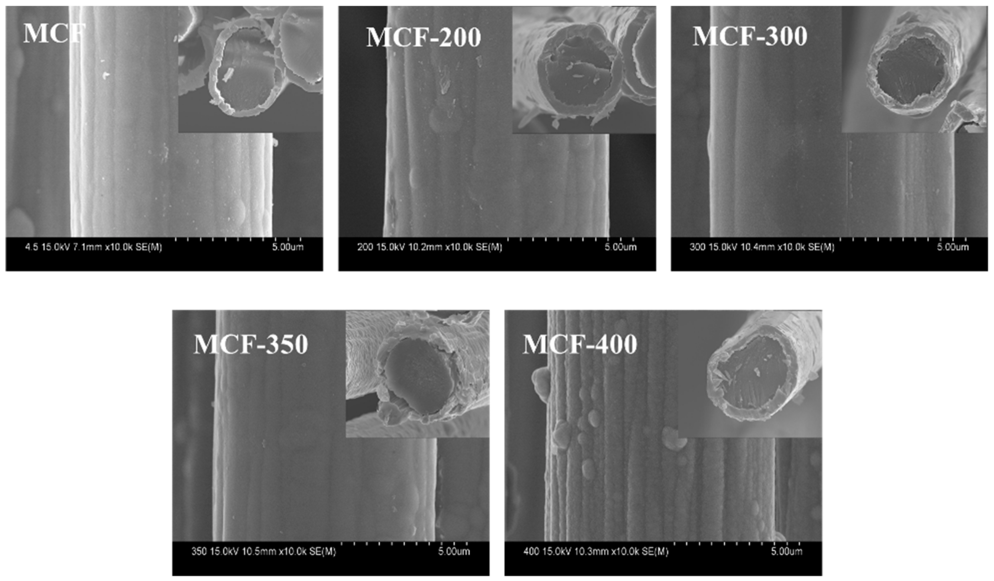
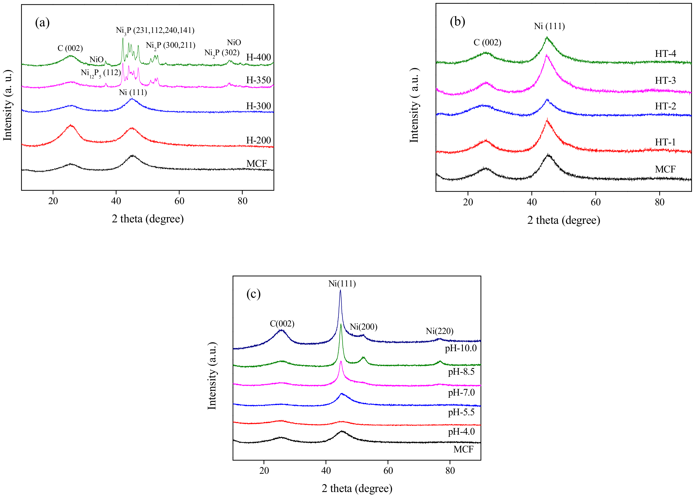
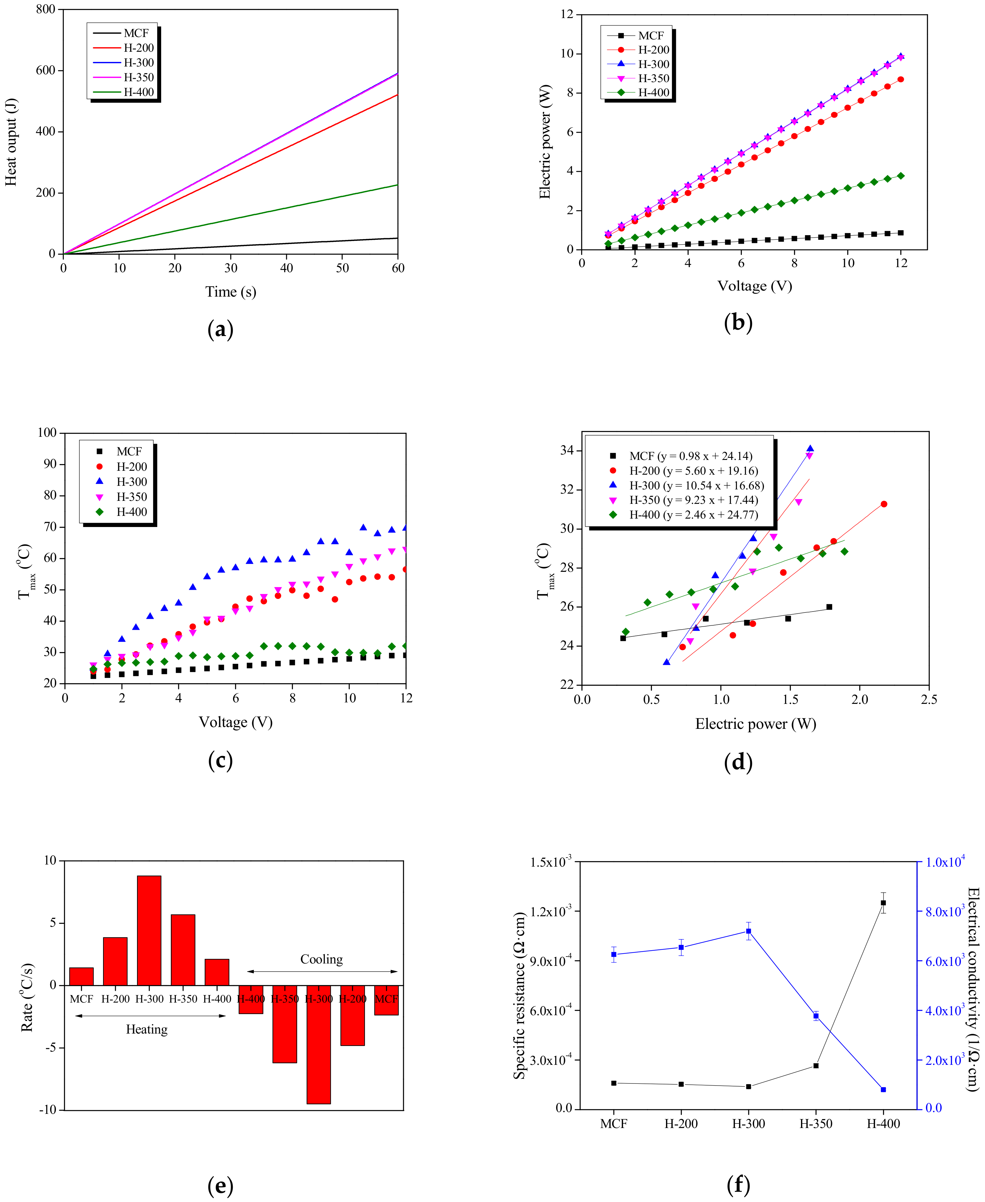
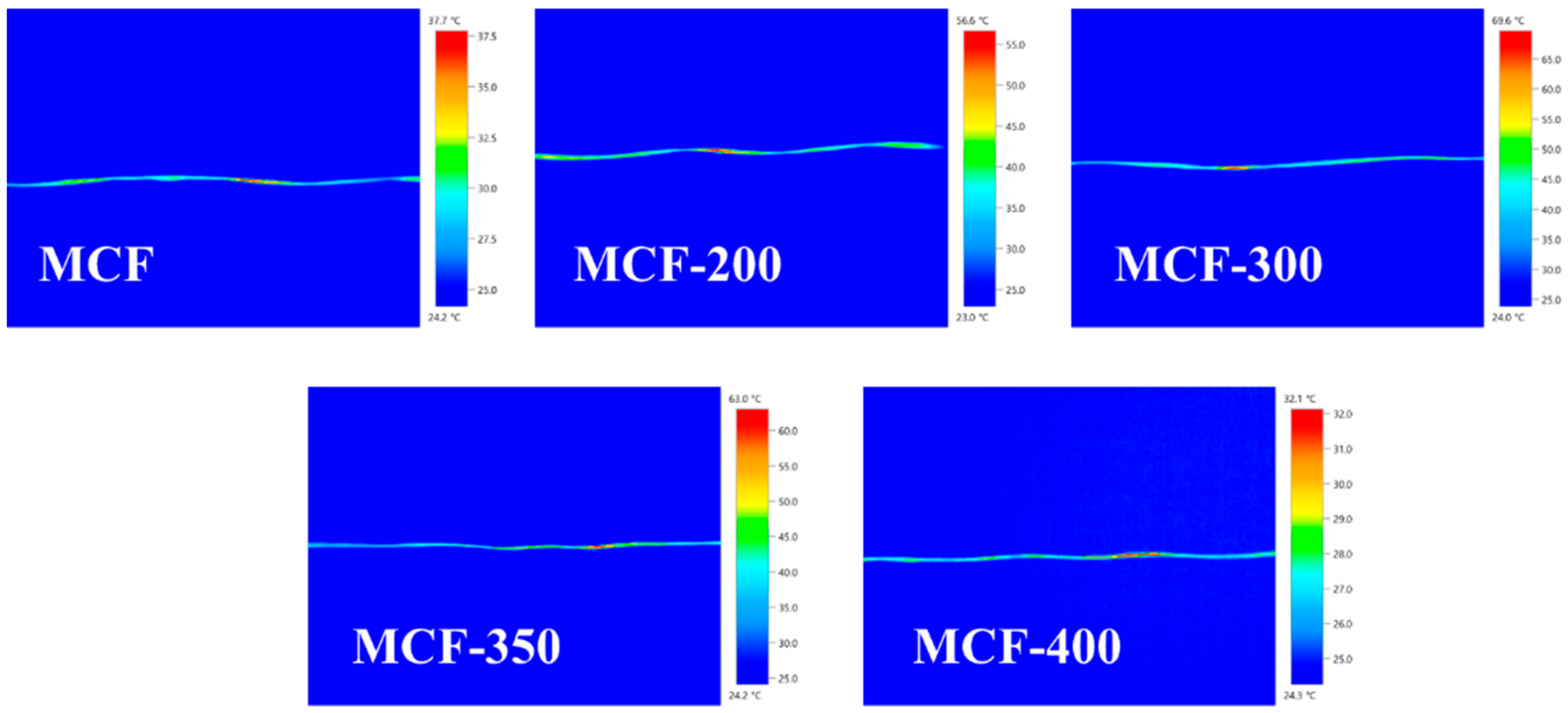
3.1. Influence of Heat Treatment Temperature

Figure 1 shows the SEM images of MCF as a function of heat treatment temperature. It was showed that the diameter of MCF was around 7.2–9.0 μm (with a 0.2–2.0 μm nickel layer), and the major compound in MCF was 85–95 wt% nickel and 3–11 wt% phosphorus content. The plating was observed to be uniform, dense, and without any cracks or pores. The nickel particles formed a perfect nickel layer [14].
The XRD patterns of MCF as a function of heat treatment temperature are shown in Figure 2a. Heat treatment at a temperature higher than 300 °C resulted in a mixture of stable Ni, Ni2P, and Ni3P phases, which was attributed to the crystallization of plating starting at ~342 °C [15]. In addition to the stable Ni, Ni2P, Ni3P, NiO, and Ni12P5 phases were observed at 350 °C. The results implied that nickel particles grew rapidly with increasing the heat treatment temperature. The grain size calculated using the Scherrer formula [16] increased from 25.78 nm for heat treatment at 200 °C (H-200) to 34.63 nm for H-400 (Table 2).
The heat output was provided by electrical energy, which was absorbed by MCF. The absorbed heat was a product of specific heat mass and temperature change. For a constant specific heat of 0.83 J/g·K (specific heat of CFs (or graphite [17])), the heat output was calculated as shown in Figure 3a. The heat output after 60 s of heating was 53, 521, 591, 589, and 226 J, respectively. After the initial period (<10 s), the heat output increased linearly over time, as the electrical energy input also increased linearly over time for a given power. Hence, H-300 provided temperatures (up to 69.6 °C) much higher than those provided by MCF, probably because of the surface structure of MCF, as well as the heat treatment temperature. The fast response was attributed to the higher thermal conductivity resulting from the metal plating. The overall performance of MCF was superior.
The electric power (P) associated with the flow of a current (I) under an applied voltage (V) is given by P = VI. In combination with Ohm’s law [18] of V = IR, the electric power is also expressed as P = V2R, where the electric power is quadratically proportional to the voltage. Consistently, for MCF with different heat treatment temperatures, the electric power increased quadratically with respect to the applied voltage, as can be seen in Figure 3b.
Figure 3c shows the voltage dependence of the Tmax of MCF under various heat treatment temperatures. The increment of the Tmax values with the applied voltage was much higher for MCF with a 300 °C heat treatment temperature. For instance, for H-300, a Tmax of ~69.6 °C was attained at an applied voltage of 12 V, which was ~32.1 °C higher than that of H-400. On the other hand, it was found that the Tmax values were quadratically increased with the increment of the applied voltage.
The Tmax of MCF at different electric power are shown in Figure 3d. Each MCF was tested for 100 s at a single step. At different electric power, the Tmax of MCF increased with increasing heat treatment temperature. The heating response of MCF-H300 was the highest. Moreover, MCF-H300 showed a 139% increase in Tmax compared with MCF. The increment in the kinetic or vibrational energy of the atoms manifested itself as heat, which gave rise to an increase in the temperature of CFs. In this way, the electric power was converted to heat by the resistance heating or Joule heating process [19].
The heating/cooling rates of MCF as a function of heat treatment temperature are presented in Figure 3e. The heating rate curves in the figure can be explained in terms of thermal mass, the mass of H-400 being the lowest and that of H-300 being the highest. The temperature change induced by electrical input depended on the thermal capacitance per area; thus, H-300 was expected to provide the highest thermal response.
The specific resistivity and electrical conductivity of the MCF are presented in Figure 3f. By using the relation R = p (L/A) [20], where L is the MCF length and A is the cross-sectional area of the MCF, the electric resistivity (p) of the MCF was calculated. As the heat treatment temperature increased, the specific resistance decreased and then increased again. Furthermore, it was observed that the specific resistance of H-300 was over 1.39 × 10⁻⁴ Ω·cm, but that this value decreased dramatically with increasing heat treatment temperature up to 400 °C [21].
Clarebrough et al. [22] showed that the electrical resistance of metallic nickel decreased with an increase in temperature of heat treatment. It is well known that the heat treatment processes proceed in three stages: recovery, re-crystallization, and grain size growth. In the recovery stage, the absorbed energy of heat treatment was used to order the Ni-P microstructure by augmentative fluctuation or to decrease the dislocations of accumulated Ni-P atoms.
After heat treatment at 400 °C, the specific resistance decreased because the amorphous MCF changed into crystalline MCF. In addition, it was obvious that the interfacial bonding between Ni-P and CFs was enhanced because of a slight catalyzing effect of the MCF. As confirmed in previous work [23], a suitable amount of metal particles can lead to better filler-matrix interaction. It is generally accepted that its success, to a large extent, depends on the metal (Ni-P)–CFs physical bonding that determine the degree of adhesion at the interfaces. These interactions depend on the filler surfaces’ active functional groups, surface energy, and energetically different crystallite faces [24,25]. This resulted in a decrease in the resistivity of MCF-H400 by 13% compared with that of MCF. The good specific resistance of MCF-H400 indicated a strong correlation between resistivity and heat treatment temperature.
As shown in Figure 4, when 12 V were applied at room temperature, the surface heating temperature of MCF-300 was 69.6 °C. In addition, the average temperature according to the heat treatment temperature was 29.1 ± 1.0 °C, 56.5 ± 2.0 °C, 69.6 ± 2.0 °C, 63.0 ± 2.0 °C, and 32.1 ± 2.0 °C, respectively. The surface temperature of the carbon heating element showed a 1.1 times higher surface temperature than MCF. The surface temperature of the carbon heating element applied at 12 V increased in proportion to the voltage, starting from room temperature, and reached about a constant temperature after about 1 min, indicating the thermal stability. These results indicated that as the heat treatment temperature increased and as the crystallinity of the CFs increased, the electric resistance decreased and the current applied under each voltage increased. [26].

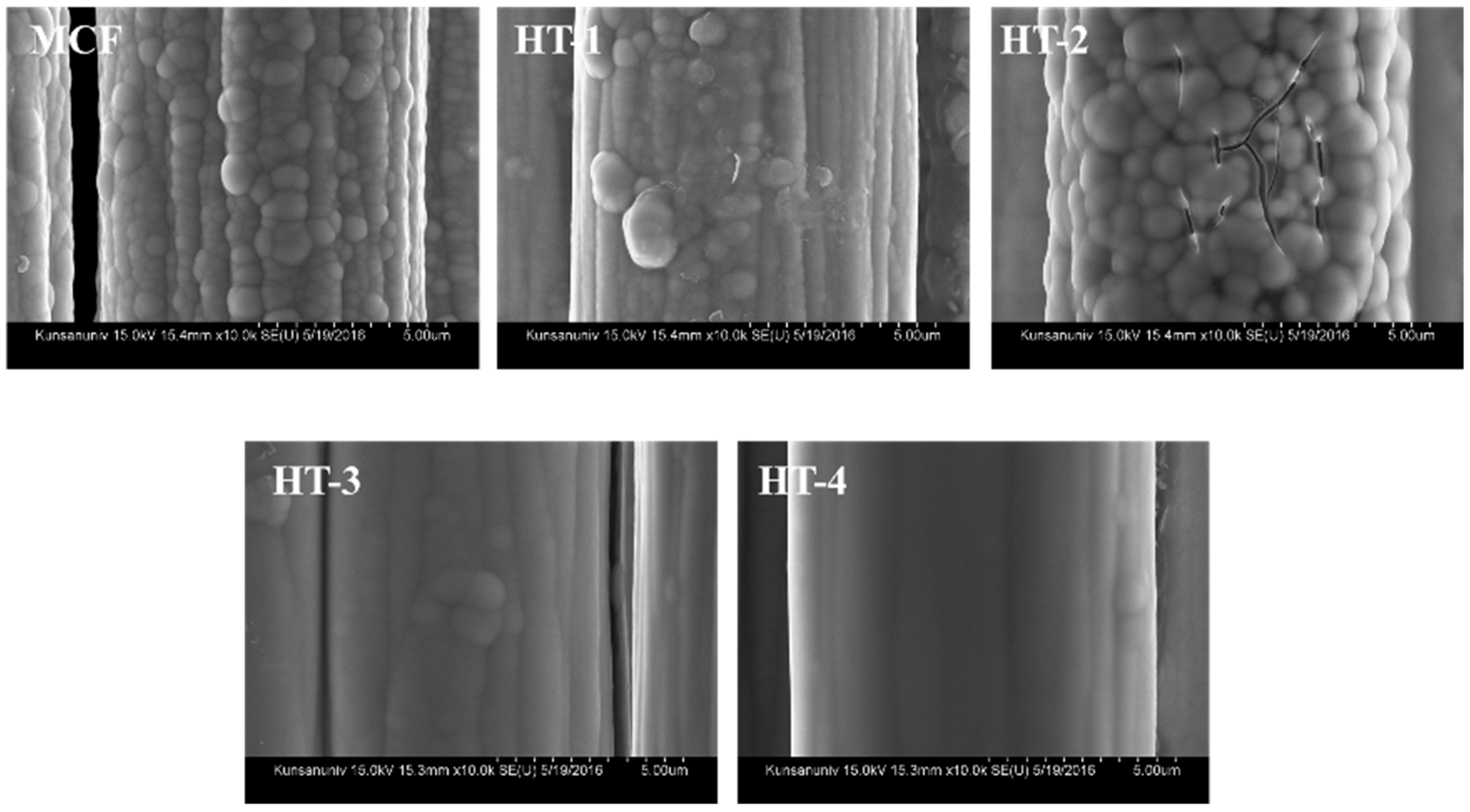
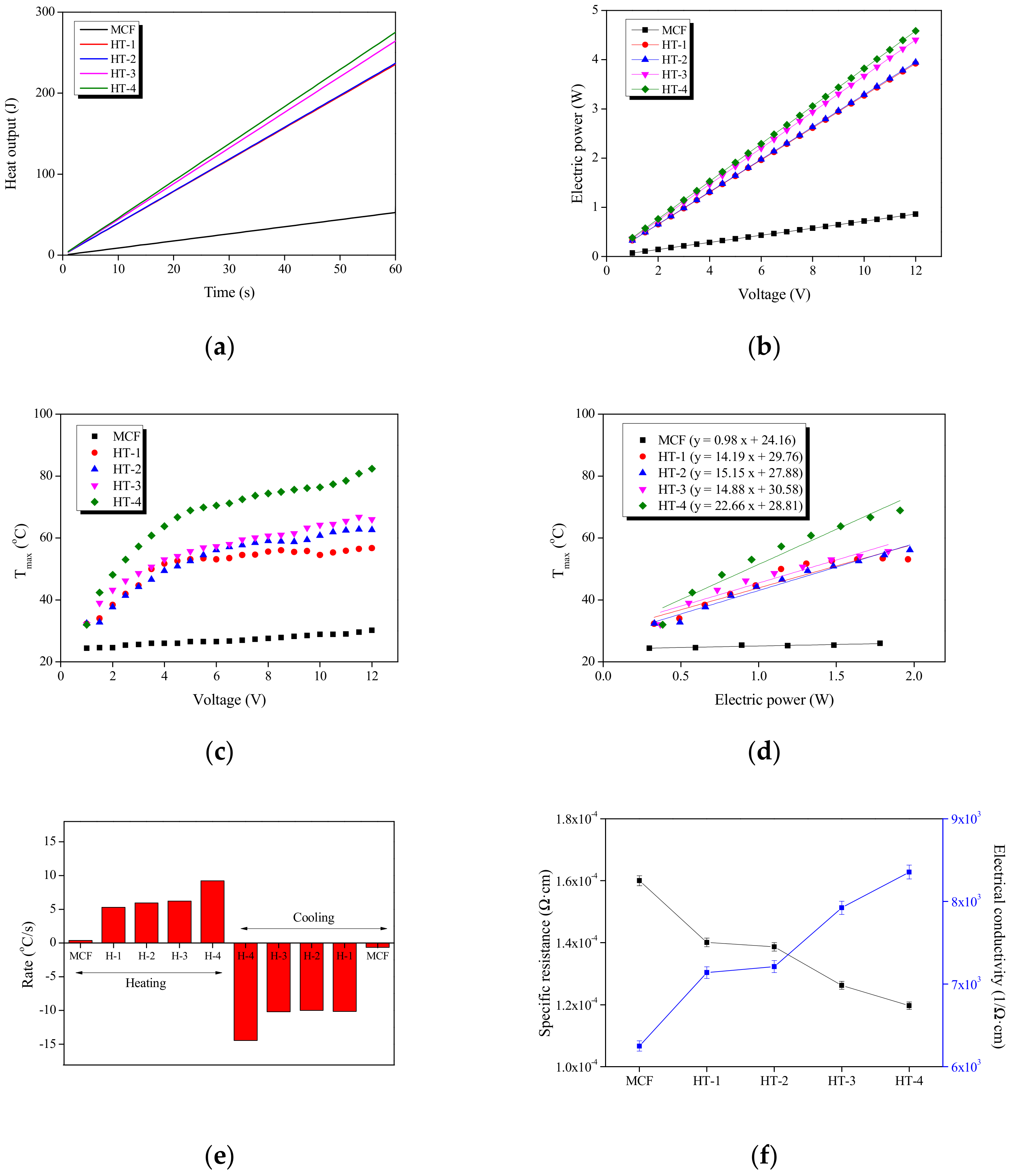
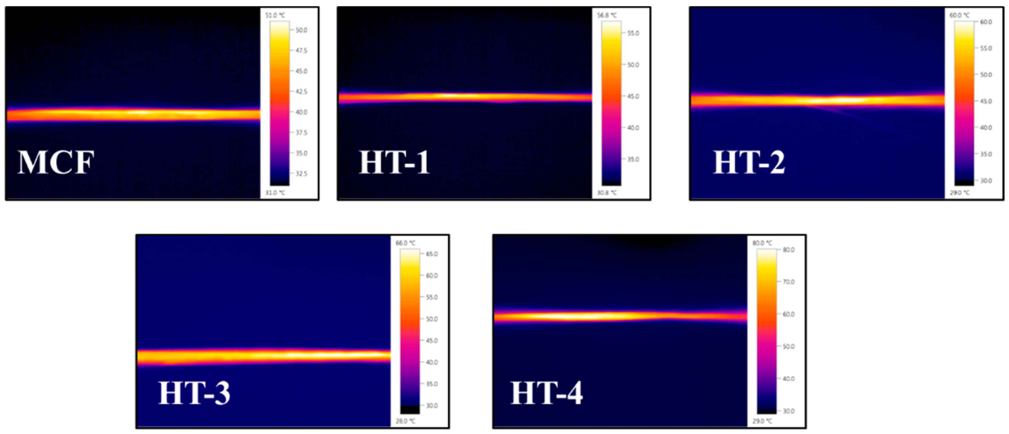
3.2. Influence of Heat Treatment Time

Figure 2b shows the variation in the XRD patterns with heat treatment time. The peak intensity of the X-ray diffraction patterns of MCF increased as the heat treatment time increased. The intensity of the peaks was primarily attributable to the microcrystalline structure or amorphous structure of the Ni-P plating, which was supersaturated with respect to the phosphorous. The relative intensity of Ni (111) increased with increasing heat treatment time. With increasing heat treatment time, the average grain size from 1.63 nm to 1.70 nm monotonically increased [27].
The heat output of MCF as a function of heat treatment time is presented in Figure 5 and Figure 6a. The heat output had a linear relationship with time. The heat output in the figure could be explained in terms of electrical energy, the heat output of the heat treatment time of 1 hour (HT-1) being the lowest and that of HT-4 being the highest.
The electric power-voltage (P-V) curves of MCF with different heat treatment times are shown in Figure 6b. For MCF, there was almost no electric current over the applied voltage of 1–12 V. On the other hand, in the cases of HT-4, the electric current increased linearly with the applied voltage, and the slopes of the P-V curves increased significantly with the heat treatment time. This demonstrated that the Ni-P nanoparticles were physically connected to each other in the CFs, and the networking degree was strengthened with the increment of the heat treatment time [28].
Figure 6c shows the Tmax of MCF as a function of heat treatment time. Compared with HT-1, HT-4 exhibited a 40.8% increase in the average Tmax under an applied voltage of 12 V. Electric heating was converted from electrical energy to thermal energy. Thus, Tmax increased with increasing applied voltages. The quadratic increase of Tmax with the applied electric power was quite consistent with the P-V curves (Figure 6b), which dictated that the electric power resulted in an efficient temperature increase as in Figure 6d.
As shown in Figure 7, when the 12 V were applied at room temperature, the surface heating temperature of HT-4 was 80.0 °C. In addition, the average temperature according to the heat treatment temperature was 29.1 ± 1.0 °C, 56.8 ± 2.0 °C, 60.0 ± 2.0 °C, 66.0 ± 2.0 °C, and 80.0 ± 2.0 °C, respectively. The surface temperature of the carbon heating element showed a 2.7 times higher surface temperature than MCF.

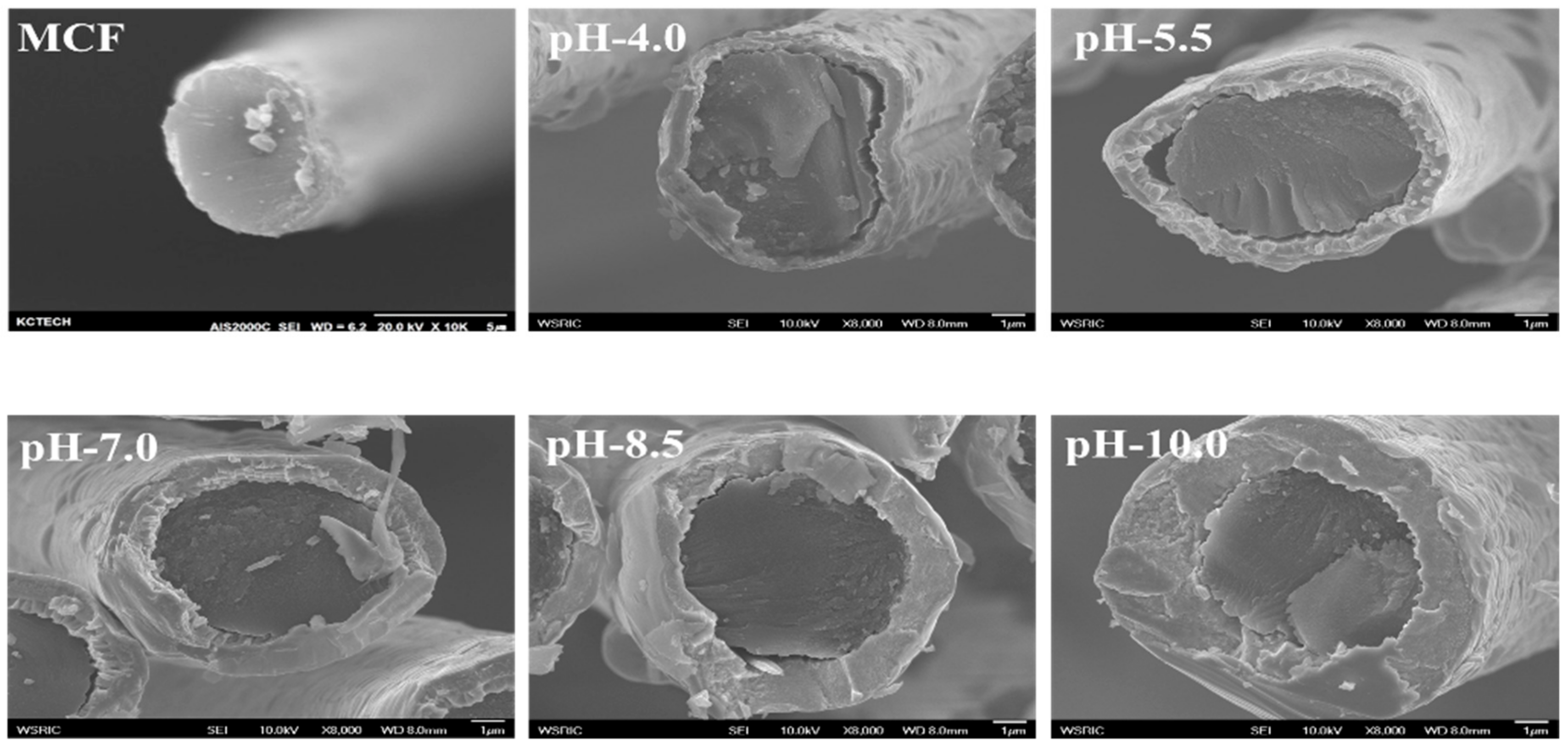
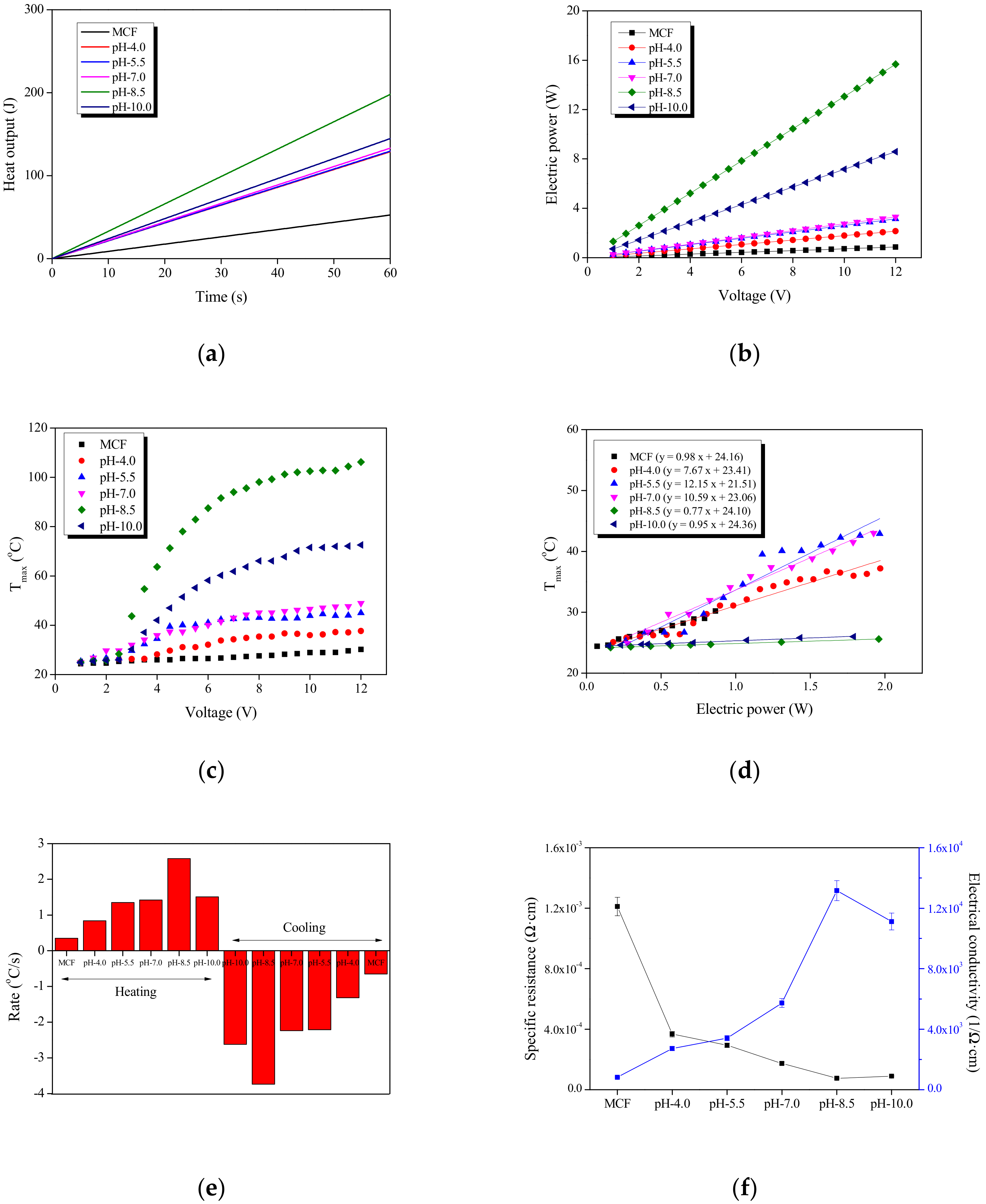
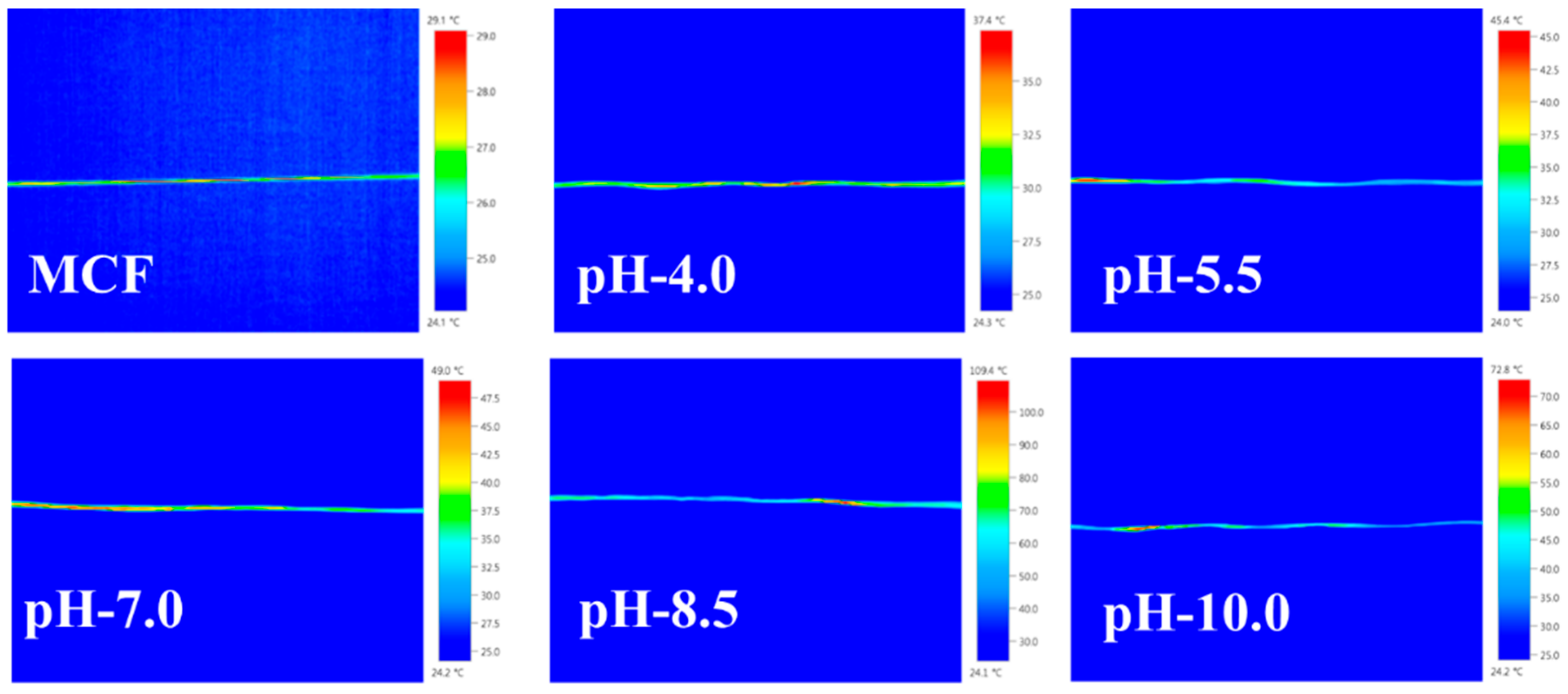
3.3. Influence of pH of the Plating Bath

Figure 8 shows SEM images of MCF manufactured according to the different pH of the plating bath. As the pH of the plating bath increased, the gaps in the axial direction disappeared from the surface of the CFs, and the CFs’ diameter and plating thickness increased. This was judged to be a change in the process of introducing oxygen and forming radicals on the surface of the fiber by oxygen penetration, and it was expected that this would affect the thermal characteristics.
The XRD patterns of MCF as a function of the pH of the plating bath are shown in Figure 2c. It is evident from Figure that at low pH (pH-4.0), MCF were amorphous in nature, whereas at high pH (pH-10.0), they had a crystalline nature. The Ni (111) peak became sharper as the pH value increased. The grain size increased from 1.34 nm for pH-4.0 to 8.31 nm for pH-8.5.
A linear relationship between the electric power and Tmax was established, as shown in Figure 9d. According to this result, the desired Tmax could be controlled effectively by adjusting the applied electric power. From the Tmax vs. electric power curves of pH-4.0 and pH-8.5, the consumption of electric power of 1 W led to Tmax values of ~37.4 °C and ~109.4 °C, respectively, indicating that pH-8.5 had better electric energy efficiency by reaching a higher maximum temperature at the same applied electric power.
In the widely studied composition range of 3–14 wt% phosphorus, the lower range between 3 and 7 wt% phosphorus was reported to be microcrystalline, and the higher range between 7 and 14 wt% phosphorus was amorphous [29,30]. Upon variation of the pH value from 4.0 to 10.0, the phosphorus content exhibited a decreasing trend in the range of 3.5–10.6 wt%, whereas the nickel content in increased to 89.4–96.5 wt%. Therefore, it was also expected that electroless Ni deposited with lower P content tended to be crystalline and have a higher conductivity [31]. The optimum pH range was found to be 8 to 9.
A linear relationship between the electric power and Tmax was established, as shown in Figure 9d. According to this result, the desired Tmax value could be effectively controlled by adjusting the applied electric power. From the Tmax vs. electric power curves at pH 4.0 and pH 8.5, the a consumed electric power of 1 W led to Tmax values of ~37.4 and ~109.4 °C, respectively, indicating that pH 8.5 produced heating elements with better efficiency as they reached a higher maximum temperature for a given amount of applied electric power.
The heating/cooling rate of MCF as a function of the processing parameters is presented in Figure 9e. The heating/cooling rate had a linear relationship with the process parameters [32]. The heating rate of MCF-H300, H-4, and pH-8.5 were the highest. Moreover, MCF-H300, H-4, and pH-8.5 respectively showed a 139%, 174%, and 42% increase in Tmax compared with MCF. This improvement in thermal emission efficiency could be attributed to the fact that the appropriate heat treatment of Ni-P crystals on CFs created more emissive surface sites, affording not only the maximum temperature, but also the maximum heating rate.
As shown in Figure 6f and Figure 9f, the resistivity slightly decreased from 1.40 × 10⁻⁴ Ω·cm to 1.19 × 10⁻⁴ Ω·cm as the heat treatment time increased during heat treatment of MCF, and as the pH of the plating bath increased, the electrical conductivity of MCF increased from 4.63 × 10³ Ω·cm to 1.66 × 10⁴ Ω·cm. The specific resistance of the nickel layer was primarily a result of grain boundary scattering. Therefore, the specific resistance decreased because of the annihilation of grain boundaries by heat treatment [33]. From the results in the range of pH 4.0–10.0, there was a strong correlation between the electrical conductivity and the pH of the plating bath. This meant that a perfect nickel layer could be formed in the range of pH 4.0–10.0 for the plating bath, resulting in a saturation state of electrical conductivity because of the contact between nickel particles [34].
As shown in Figure 10, when the 12 V were applied at room temperature, the surface heating temperature of pH-10.0 was 41.5 °C. In addition, the average temperature according to the pH of the plating bath was 29.1 ± 1.0 °C, 29.4 ± 2.0 °C, 31.9 ± 2.0 °C, 34.4 ± 2.0 °C, 35.5 ± 2.0 °C, and 41.5 ± 2.0 °C, respectively. The surface temperature of the carbon heating element showed a 1.4 times higher surface temperature than MCF.

4. Conclusions

The influence of process parameters such as heat treatment temperature, heat treatment time, and the pH of the plating bath on the thermal and electrical properties of MCF was investigated. By controlling the reaction parameters, a uniform Ni-P nanoparticle was deposited on the surface of CFs by electroless plating at a temperature of 300 °C, a time of 4 h, and a plating bath pH of 8.5. The Ni-P plating on CFs surface led to an increase in two phases, i.e., microcrystalline and amorphous. This was mostly a result of the increase in the stable Ni, Ni2P, Ni3P, and NiO phases, as well as the metastable Ni12P5 phase. The pH of the plating bath had major effects on the P content. The mean particle size of Ni-P nanoparticles with approximately 6–9 wt% phosphorus was 0.9–1.0 nm. This provided Tmax up to 69.6, 80, and 106.2 °C and heat output after 60 s up to 591, 275, and 198 J, respectively. Under the operating condition at 12 V, the heating rate of MCF could reach 8.79 °C/s, 9.23 °C/s, and 2.58 °C/s, respectively. The Tmax of MCF could be finely controlled by adjusting the applied voltage.

Author Contributions

Writing—original draft, B.-K.C.; Writing—review & editing, S.-J.P. and M.-K.S. All authors have read and agreed to the published version of the manuscript.

Funding

This research was funded by National Research Foundation of Korea: 2018M3C1B5052282.

Acknowledgments

This research was supported by the Traditional Culture Convergence Research program through the National Research Foundation of Korea (NRF) funded by the Ministry of Science, ICT & Future Planning (2018M3C1B5052282).

Conflicts of Interest

The authors declare no conflict of interest.

References

  1. Lee, B.M.; Jung, J.M.; Hwang, I.T.; Shin, J.; Shin, J.; Hong, S.K.; Jung, C.H.; Jeong, Y.G.; Choi, J.H. Fabrication and electric heating behavior of carbon thin films from water soluble poly (vinyl alcohol) via simple dry and ambient stabilization and carbonization. Appl. Surf. Sci. 2018, 456, 561–567. [Google Scholar] [CrossRef]
  2. Doblas, A.; Rosario, G.D.; Prolongo, M.G.; Prolongo, S.G. Electric heating performance of nanodoped polyurethane coatings. Prog. Org. Coat. 2019, 135, 185–190. [Google Scholar] [CrossRef]
  3. Xi, X.; Chung, D.D.L. Colossal electric permittivity discovered in polyacrylonitrile (PAN) based carbon fiber, with comparison of PAN-based and pitch-based carbon fibers. Carbon 2019, 145, 734–739. [Google Scholar] [CrossRef]
  4. Ming, Y.; Duan, Y.; Zhang, S.; Zhu, Y.; Wang, B. Self-heating 3D printed continuous carbon fiber/epoxy mesh and its application in wind turbine deicing. Polym. Test. 2020, 82, 106309. [Google Scholar] [CrossRef]
  5. Xu, X.; Zhang, Y.; Jiang, J.; Wang, H.; Zhao, X.; Li, Q.; Lu, W. In-situ curing of glass fiber reinforced polymer composites via resistive heating of carbon nanotube films. Compos. Sci. Technol. 2017, 149, 20–27. [Google Scholar] [CrossRef]
  6. Kim, B.J.; Choi, W.K.; Um, M.K.; Park, S.J. Effects of nickel coating thickness on electric properties of nickel/carbon hybrid fibers. Surf. Coat. Technol. 2011, 205, 3416–3421. [Google Scholar] [CrossRef]
  7. Zhou, H.; Yu, Q.; Peng, Q.; Wang, H.; Chen, J.; Kuang, Y. Catalytic graphitization of carbon fibers with electrodeposited Ni–B alloy coating. Mater. Chem. Phys. 2008, 110, 434–439. [Google Scholar] [CrossRef]
  8. Tzeng, S.S.; Lin, Y.H. The role of electroless Ni–P coating in the catalytic graphitization of PAN-based carbon fibers. Carbon 2008, 46, 544–561. [Google Scholar] [CrossRef]
  9. Sribalaji, M.; Arunkumar, P.; Babu, K.S.; Keshri, A.K. Crystallization mechanism and corrosion property of electroless nickel phosphorus coating during intermediate temperature oxidation. Appl. Surf. Sci. 2015, 355, 112–120. [Google Scholar] [CrossRef]
  10. Sorkhabi, H.A.; Rafizadeh, S.H. Effect of coating time and heat treatment on structures and corrosion characteristics of electroless Ni–P alloy deposits. Surf. Coat. Technol. 2004, 176, 318–326. [Google Scholar] [CrossRef]
  11. Qin, X.; Lu, Y.; Xiao, H.; Wen, Y.; Yu, Y. A comparison of the effect of graphitization on microstructures and properties of polyacrylonitrile and mesophase pitch-based carbon fibers. Carbon 2012, 50, 4459–4469. [Google Scholar] [CrossRef]
  12. Chugh, R.; Chung, D.D.L. Flexible graphite as a heating element. Carbon 2002, 40, 2285–2289. [Google Scholar] [CrossRef]
  13. Fan, Y.; Yang, H.; Liu, X.; Zhu, H.; Zou, G. Preparation and study on radar absorbing materials of nickel-coated carbon fiber and flake graphite. J. Alloys Compd. 2008, 461, 490–494. [Google Scholar] [CrossRef]
  14. Choi, B.K.; Choi, W.K.; Rhee, K.Y.; Park, S.J.; Seo, M.K. Influence of heat treatment temperature on structure and exothermic properties of electroless Ni-P plating carbon fiber heating elements. Compos. B 2019, 167, 676–682. [Google Scholar] [CrossRef]
  15. Chien, A.T.; Cho, S.; Joshi, Y.; Kumar, S. Electrical conductivity and Joule heating of polyacrylonitrile/carbon nanotube composite fibers. Polymer 2014, 55, 6896–6905. [Google Scholar] [CrossRef]
  16. Tzeng, S.S. Catalytic graphitization of electroless Ni–P coated PAN-based carbon fibers. Carbon 2006, 44, 1986–1993. [Google Scholar] [CrossRef]
  17. Kim, T.; Chung, D.D.L. Carbon fiber mats as resistive heating elements. Carbon 2003, 41, 2427–2451. [Google Scholar] [CrossRef]
  18. Gupta, A.; Dhakate, S.R.; Pal, P.; Dey, A.; Iyer, P.K.; Singh, D.K. Effect of graphitization temperature on structure and electrical conductivity of poly-acrylonitrile based carbon fibers. Diam. Relat. Mater. 2017, 78, 31–38. [Google Scholar] [CrossRef]
  19. Li, M.; Jeong, Y.G. Poly(ethylene terephthalate)/exfoliated graphite nanocomposites with improved thermal stability, mechanical and electrical properties. Compos. A 2011, 42, 560–566. [Google Scholar] [CrossRef]
  20. Jang, H.S.; Jeon, S.K.; Nahm, S.H. The manufacture of a transparent film heater by spinning multi-walled carbon nanotubes. Carbon 2011, 49, 111–116. [Google Scholar] [CrossRef]
  21. Isaji, S.; Bin, Y.; Matsuo, M. Electrical conductivity and self-temperature-control heating properties of carbon nanotubes filled polyethylene films. Polymer 2009, 50, 1046–1053. [Google Scholar] [CrossRef]
  22. Chae, H.G.; Sreekumar, T.V.; Uchida, T.; Kumar, S. A comparison of reinforcement efficiency of various types of carbon nanotubes in polyacrylonitrile fiber. Polymer 2005, 46, 10925–10935. [Google Scholar] [CrossRef]
  23. Kar, K.K.; Sathiyamoorthy, D. Influence of process parameters for coating of nickel–phosphorous on carbon fibers. J. Mater. Process. Technol. 2009, 209, 3022–3029. [Google Scholar] [CrossRef]
  24. Huang, C.Y.; Mo, W.W.; Roan, M.L. The influence of heat treatment on electroless-nickel coated fibre (ENCF) on the mechanical properties and EMI shielding of ENCF reinforced ABS polymeric composites. Surf. Coat. Technol. 2004, 184, 123–132. [Google Scholar] [CrossRef]
  25. Park, J.; Jeong, Y.G. Investigation of microstructure and electric heating behavior of hybrid polymer composite films based on thermally stable polybenzimidazole and multiwalled carbon nanotube. Polymer 2015, 59, 102–109. [Google Scholar] [CrossRef]
  26. Chu, K.; Yun, D.J.; Kim, D.; Park, H.; Park, S.H. Study of electric heating effects on carbon nanotube polymer Composites. Org. Electron. 2014, 15, 2734–2741. [Google Scholar] [CrossRef]
  27. Jeong, Y.G.; An, J.E. Effects of mixed carbon filler composition on electric heating behavior of thermally-cured epoxy-based composite films. Compos. A 2014, 56, 1–7. [Google Scholar] [CrossRef]
  28. An, J.E.; Jeong, Y.G. Structure and electric heating performance of graphene/epoxy composite films. Eur. Polym. J. 2013, 49, 1322–1330. [Google Scholar] [CrossRef]
  29. Tzeng, S.S.; Chang, F.Y. Electrical resistivity of electroless nickel coated carbon fibers. Thin Solid Films 2001, 388, 143–149. [Google Scholar] [CrossRef]
  30. Kang, S.S.; Ji, H.; Gul, H.Z.; Sakong, W.K.; Kim, J.Y.; Kim, W.S.; Lee, J.; Han, S.; Park, M.; Choi, Y.C. Metal-coated carbon fiber for lighter electrical metal wires. Synthetic Metals 2016, 222, 180–185. [Google Scholar] [CrossRef]
  31. Deka, B.K.; Hazarika, A.; Kong, K.; Kim, D.Y.; Park, Y.B.; Park, H.W. Interfacial resistive heating and mechanical properties of graphene oxide assisted CuO nanoparticles in woven carbon fiber/polyester composite. Compos. A 2016, 80, 159–170. [Google Scholar] [CrossRef]
  32. Kim, M.; Sung, D.H.; Kong, K.; Kim, N.; Kim, B.J.; Park, H.W.; Park, Y.B.; Jung, M.; Lee, S.H. Characterization of resistive heating and thermoelectric behavior of discontinuous carbon fiber-epoxy composites. Compos. B 2016, 90, 37–44. [Google Scholar] [CrossRef]
  33. Chu, K.; Park, S.H. Electrical heating behavior of flexible carbon nanotube composites with different aspect ratios. J. Ind. Eng. Chem. 2016, 35, 195–198. [Google Scholar] [CrossRef]
  34. Tang, P.; Zhang, R.; Chen, Z.; Yang, B.; Bin, Y. Effect of c-ray irradiation on the microstructure and self-heating property of carbon fiber/polyethylene composite films. Compos. A 2015, 78, 174–180. [Google Scholar] [CrossRef]
Figure 1. SEM images of MCF as a function of heat treatment temperature.
Carbon 06 00006 g001
Figure 2. XRD patterns of MCF as a function of the processing parameters: (a) heat treatment temperature, (b) heat treatment time, and (c) pH of the plating bath.
Carbon 06 00006 g002
Figure 3. Thermal and electrical properties of MCF as a function of heat treatment temperature: (a) heat output, (b) electric power-voltage curves, (c) applied voltage changes of Tmax, (d) electric power changes of Tmax, (e) heating/cooling rate, and (f) electrical properties.
Carbon 06 00006 g003
Figure 4. Thermo-graphic camera images of MCF as a function of heat treatment temperature.
Carbon 06 00006 g004
Figure 5. SEM images of MCF as a function of heat treatment time.
Carbon 06 00006 g005
Figure 6. Thermal and electrical properties of MCF as a function of heat treatment time: (a) heat output, (b) electric power-voltage curves, (c) applied voltage changes of Tmax, (d) electric power changes of Tmax, (e) heating/cooling rate, and (f) electrical properties.
Carbon 06 00006 g006
Figure 7. Thermo-graphic camera images of MCF as a function of heat treatment time.
Carbon 06 00006 g007
Figure 8. SEM images of MCF as a function of the pH of the plating bath.
Carbon 06 00006 g008
Figure 9. Thermal and electrical properties of MCF as a function of the pH of the plating bath: (a) heat output, (b) electric power-voltage curves, (c) applied voltage changes of Tmax, (d) electric power changes of Tmax, (e) heating/cooling rate, and (f) electrical properties.
Carbon 06 00006 g009
Figure 10. Thermo-graphic camera images of MCF as a function of the pH of the plating bath.
Carbon 06 00006 g010
Table 1. Process conditions for electroless Ni-P plating of CFs.
ConditionsSample NameHeat Treatment Temperature (°C)pH 1Holding Time (h)Average Plating Thickness (μm) 2
Heat treatment temperatureH-2002004.011.47 ± 0.01
H-3003001.64 ± 0.01
H-3503501.53 ± 0.01
H-4004001.48 ± 0.01
Heat treatment timeHT-13004.011.42 ± 0.01
HT-221.42 ± 0.01
HT-331.41 ± 0.01
HT-441.40 ± 0.01
pH of plating bathpH-4.0-4.0-0.61 ± 0.03
pH-5.55.50.73 ± 0.03
pH-7.07.01.28 ± 0.03
pH-8.58.51.64 ± 0.03
pH-10.010.02.31 ± 0.03
1 Electroless bath temperature: 80–90 °C, 2 average plating thickness of metal plating CFs (MCF): 1.42 ± 0.01 μm.
Table 2. Microcrystalline structural parameters of MCF as a function of processing parameters.
002 Peak111 Peak
2 ThetaLc 12 ThetaLa 2
MCF25.581.0545.291.37
H-20025.2712.6145.2025.78
H-30025.1210.9745.3829.65
H-35025.5911.0744.7931.78
H-40025.3713.1044.6434.63
HT-125.221.1945.141.63
HT-225.040.9045.201.64
HT-325.391.2645.071.65
HT-425.351.0145.101.70
pH-4.025.161.0645.341.34
pH-5.524.801.1345.252.02
pH-7.025.641.2144.806.59
pH-8.525.421.1844.848.31
pH-10.025.271.3844.648.29
1 Crystallite thickness (nm), 2 crystallite size (nm).

