Power Cycling and Reliability Testing of Epoxy-Based Graphene Thermal Interface Materials
by
 , and
, and
Jacob S. Lewis
* ,
,
Timothy Perrier
,
Amirmahdi Mohammadzadeh
,
Fariborz Kargar
and
Alexander A. Balandin
* Phonon Optimized Engineered Materials (POEM) Center, Department of Electrical and Computer Engineering, Materials Science and Engineering Program, Bourns College of Engineering, University of California-Riverside, Riverside, CA 92521, USA
*
Authors to whom correspondence should be addressed.
C 2020, 6(2), 26; https://0-doi-org.brum.beds.ac.uk/10.3390/c6020026
Submission received: 24 March 2020
/
Revised: 16 April 2020
/
Accepted: 21 April 2020
/
Published: 25 April 2020
(This article belongs to the Collection Nanocarbon-Based Composites and Their Thermal, Electrical, and Mechanical Properties)
Abstract
:We report on the lifespan evolution of thermal diffusivity and thermal conductivity in curing epoxy-based thermal interface materials with graphene fillers. The performance and reliability of graphene composites have been investigated in up to 500 power cycling measurements. The tested composites were prepared with an epoxy resin base and randomly oriented fillers consisting of a mixture of few-layer and single-layer graphene. The power cycling treatment procedure was conducted with a custom-built setup, while the thermal characteristics were determined using the “laser flash” method. The thermal conductivity and thermal diffusivity of these composites do not degrade but instead improve with power cycling. Among all tested filled samples with different graphene loading fractions, an enhancement in the thermal conductivity values of 15% to 25% has been observed. The obtained results suggest that epoxy-based thermal interface materials with graphene fillers undergo an interesting and little-studied intrinsic performance enhancement, which can have important implications for the development of next-generation thermal interface materials.
1. Introduction
The consistent miniaturization of semiconductor-based circuit elements has, despite efficiency gains, resulted in the unintended increase in waste power density in such products. Semiconductor circuits designed specifically for signal amplification have seen improvements in power at higher operating frequencies at the cost of substantial and detrimental waste heat production. Decreasing the operating temperature of GaN transistors by 20 °C increases the device’s mean time to failure by an order of magnitude [1]. Additionally, electronic products that directly interact with radiative energy, such as photovoltaic cells and light-emitting diodes, suffer either decreased performance or reduced lifespan at elevated operating temperatures [2,3]. Due to the comparative difficulty of directly reducing the production of waste heat in electronics, a thermal dissipative solution is the most popular, next-best option for control of device operating temperature [4]. Due to inevitable surface imperfections and the subsequent inadvertent production of air pockets between any solid-solid junction in such a solution, it is imperative to use a special material to replace the catastrophically thermally insulating air. Bridging the physical junctions between two imperfect surfaces in a thermal dissipative solution with a thin layer of material to replace these interstitial air pockets is of critical importance and serves to substantially improve thermal dissipation of the overall heat sink solution [5,6]. A material used in this manner is called a thermal interface material (TIM).
Though state-of-the-art TIMs can substantially reduce the overall thermal resistance of the dissipative solution, there remains considerable room for improvement of these materials across a wide range of parameters. One of the best classes of TIMs for reduction in junction thermal resistance are metal-based solder materials. They provide extremely low contact resistances at physical junctions and boast a typical metallic level of thermal conductivity. However, this type of TIM is difficult to process and suffers from poor reliability and a high risk of cracking failures. Investigations into these materials is often concerned with addressing lifespan reliability [7]. These drawbacks in metal solder-based TIMs are substantial enough to result in the dominance of polymeric TIMs in industry. Work to improve the performance of these polymeric TIMs often leads researchers to focus on developing more thermally conductive polymers to be used between junctions in a thermal dissipative solution and for the direct encapsulation of smaller chips in an integrated circuit [8]. In the former application, a viscous fluid capable of thermal expansion and contraction without structural damage is best suited, and in the latter, a solid, impermeable polymer to provide the chip’s sensitive circuitry with unvarying protection from the environment is preferable [9,10]. Determination of reliability and end-of-life performance of polymeric TIMs is of great interest to industry because these are the two aspects of TIMs that provide polymeric TIMs with such a preferential usage over solder-based TIMs.
There remains considerable room for improvement in the performance of polymeric TIMs. A common tactic to enhance their performance is to load polymer matrices with filler materials of considerable thermal conductivity such as aluminum oxide, silver, carbon nanotubes, and graphite [11,12,13,14,15,16]. The most important considerations in terms of used fillers are their thermal conductivity, geometry, coefficient of thermal expansion, and concentration in the mixture. At high loading fractions, f ≈ 30 vol%, the onset of a percolation threshold—the point at which any additional filler results in dramatic thermal conductivity improvement—has been observed [17,18]. At the microscopic level, the thermal percolation corresponds to the point when thermally conductive fillers form a continuous network. In this case, heat mostly propagates via the filler network rather than matrix material. Additionally, as has been recently shown, composites that are composed of multiple types of fillers with dissimilar geometries can exhibit synergistic improvement of thermal conductivity relative to composites of either single filler at identical total filler loading percentage [19,20,21,22,23,24,25,26,27,28].
Due to the exceptional thermal conductivity of graphene, found to be well above 2000 Wm−1K−1, and its potential to be a cheap, mass-producible material, it has seen extensive study as a potential filler material for next-generation polymeric TIMs [29,30,31,32,33,34,35,36,37,38]. Few-layer graphene retains very high thermal conductivity while offering a larger cross-sectional area, useful for both heat transfer and robustness upon contact with the matrix material. In the context of TIM research, the term “graphene fillers” is typically used to refer to a mixture of single-layer graphene and few-layer graphene flakes derived through chemical exfoliation or reduction in graphene oxide. Graphene fillers are expected to have lateral dimensions from hundreds of nm to a few µm in order to preserve the intrinsic heat conduction properties, principally influenced by the phonon mean free path. It has been demonstrated previously that TIMs with a high loading of graphene possess unprecedentedly high thermal conductivity, reaching as high as ≈11 Wm−1K−1 at a loading fraction of 45 vol% in cured and 7.1 Wm−1K−1 at 27 vol% in non-curing TIMs [17,39,40]. Additionally, graphene-filled polymers have been shown to be a very effective shielding material for electromagnetic interference, a property very useful for sensitive chip encapsulation [41]. One can expect that the thermal contact resistance of TIMs with graphene will be lower than that of TIMs with carbon nanotubes. Owing to its two-dimensional and flexible nature, graphene fillers couple better with both matrix materials and contacting surfaces. It has also been demonstrated by this research group that graphene can be used effectively in combination with boron nitride to achieve independent control of thermal and electrical conductivities [19,42].
During normal use, TIMs are subjected to a difficult environment. They are routinely operated at different temperatures, with varying junction surface morphology due to thermal expansion and warping, and must always maintain quality contact. A TIM suffers catastrophic failures over the course of its lifespan because, in case the of non-curing types, it has been pumped out of the junction, and in the case of curing types, it has cracked due to thermal stresses—both stemming from expansions and contractions [6,43]. However, the long-term, intrinsic performance of TIMs irrespective of the junctions in which they are applied has received far less consideration [44,45,46,47,48,49,50,51,52]. TIM intrinsic performance may alter due to numerous factors, including chemical and physical alterations of either the polymer matrix or the filler materials. Despite a tremendously large number of reports on the use of graphene in TIMs and other composites, we are not aware of any study concerned with the reliability or thermal cycling of graphene TIMs over the course of a realistic device lifespan. Knowledge of the long-term performance of graphene-filled TIMs is imperative for any practical application or adoption of these materials by industry.
In this paper, we report the salient thermal parameters of mono-filled graphene epoxy-based TIMs over the course of up to 500 power cycle treatments. An epoxy matrix was chosen because it is a standard material system used frequently in thermal composite investigations. It is also practically relevant, being one of the most commonly used base materials in curing TIMs. Unexpectedly, we found that instead of a degradation of the thermal conductivity of the cured graphene TIMs, it actually improved over the course of power cycling treatments. The obtained data suggest that epoxy-based thermal interface materials with graphene fillers undergo an interesting and little studied intrinsic performance enhancement. We argue that our results can have important implications for the development of next-generation TIMs with graphene and other fillers. The rest of this paper is organized as follows. In Section 2, we describe the sample preparation; in Section 3, we provide a brief background for the thermal cycling procedures and introduce the procedure used in this study; in Section 4, we present the thermal diffusivity and conductivity of graphene TIMs after a certain number of power cycle steps; in Section 5, we discuss the results of this study; in Section 6, we offer our conclusions of this study.
2. Methods
Sample preparation: The graphene and epoxy composite sample preparation procedure was in most ways identical to a previous study by this research group, save for the absence of any h-BN materials, the application of as little pressure as possible during curing, and the use of few-layer graphene (XG Sciences, Lansing, MI, USA) with a vendor-defined average lateral dimension of 25 µm [19]. The specific type of graphene product used was xGNP- H-25. According to vendor specifications, it had less than 1% of residual oxygen content, which most likely came from atmospheric contamination. This type of graphene powder is preferable to reduced graphene oxide (rGO), which has substantially larger oxygen content in the form of residual graphene oxide that degrades its thermal transport properties. First, the epoxy resin was weighed, placed in a rough vacuum environment for approximately two minutes to remove air bubbles, and then weighed once more. This final weight was then used to determine the necessary weights of all other components to achieve the desired constituent composition. Graphene powder was then added to the resin and mixed in a bladeless high-speed, planetary centrifuge (Flacktek Inc., Landrum, SC, USA) at rotational frequencies between 1500 and 2000 RPM for 90 s. At graphene loading fractions above 10 wt%, an additional mixing process of manually breaking agglomerations by needle was conducted as needed to ensure a homogeneous mixture. Then, the hardening agent was added immediately prior to a final planetary centrifuge cycle at 1500 RPM. For samples of graphene loading fractions over 15 wt%, a paper wadding-covered hand-pressed piston is applied into the mold to flatten the composite. The sample was then left to cure at room temperature for approximately 24 h before removing it from the mold. Finally, the samples were polished down to the desired dimensions of a diameter of 25.4 mm and a thickness between 1.5 and 1.8 mm. Supplemental Figures S2 and S3 show a SEM image of a fractured surface and the Raman spectrum, each of a 5.4 vol% sample without any cycling treatments. The G and 2D peaks in Supplemental Figure S3 indicate the presence of graphene and few-layer graphene in the composite. A noticeable disorder-induced D peak is explained by the defects and impurities present in graphene flakes and light scattering from the edges. It is known that lattice defects, disorder, and sample edges lead to the relaxation of the phonon scattering selection rules imposed by translation symmetry [52,53,54,55,56,57].
Density: The finalized sample densities were measured with Archimedes’ Principle using an electronic scale (Mettler Toledo, Columbus, OH, USA) for use in determining their thermal parameters. This technique relies upon measurements of mass both in and outside of water and determines density through the difference in measured mass of these two readings resultant from the object’s buoyancy force. For better accuracy, the sample’s weight in water was recorded after manually scraping off any adsorbed air bubbles and the recorded weight stabilized over time. For the purpose of this study, we converted the filler mass fraction ratio (φ) to the volume fraction (f) following the procedure described in detail to our previous published work [17].
Power cycling: The power cycling treatment procedure employed two programmable power supplies (Chroma 62000P, Foothill Ranch, CA, USA and Keithley 2400, Solon, OH, USA), a thermocouple-reading programmable benchtop multimeter (Keithley 2182A), a small electronics fan (Intel Corp., Santa Clara, CA, USA), and a Type-J thermocouple (OMEGA Engineering, Inc., Norwalk, CT, USA). A custom Nichrome wire loop heating element, with a typical diameter negligibly smaller than that of the sample, at 25.6 mm, sandwiched between two pieces of Kapton tape. A coil resistance of approximately 95 Ω was targeted in manufacture to achieve the desired power range, considering the output I-V curves of the particular power supply used. All equipment was controlled through a custom python script passing standard commands for programmable instruments (SCPI) to the appropriate equipment to allow for unattended 24 h operation. The power cycling procedure begins by finding the necessary power that power supply A needs to apply to the wire loop to reach the desired temperature of 120 °C and then holds for 8 min. It is important to note that this temperature is above the glass transition temperature of the polymer matrix, which has been reported in the literature at ≈100 °C [58,59]. Supplemental Figure S4 shows differential scanning calorimetry results, showing that the glass transition temperature does occur around this temperature. After the prescribed time is elapsed, power supply A removes all power to the wire loop and power supply B turns on the electronics fan pointed at the sample to speed the cooling phase. The temperature of the thermocouple is continuously polled and once its readings drop below 35 °C, the software pauses for another 8 min. After this time elapses, power supply A directly applies the power determined adequate in the prior step scaled to reach an equilibrium temperature of approximately 120 °C. The requisite power is re-calibrated every 50 runs should any unforeseen dramatic shift in the thermal properties of the sample come to pass. The end result of this procedure is temperatures fluctuating between 120 and ≈28 °C, depending on the local room temperature at that time. The equipment used in this procedure managed to heat and cool the sample at a rate of approximately 1 °C per second, with a much slower rate of change the closer to the temperature equilibrium point. Due to the fact that the TIM sample is subjected to a temperature gradient due to being heated from one side, most researchers refer to this procedure as power cycling instead of classic temperature cycling [6,60]. Supplemental Figure S5 shows the controlling software’s own plot of the temperature at selected times throughout the cycling procedure.
Laser flash analysis: The thermal diffusivities were directly measured laser flash analysis (LFA 467, Netzsch GmbH, Selb, Germany) experiments [61]. In this technique, a light excitation source such as a Xenon lamp irradiates upon one surface of a sample. The absorption of this light results in a local increase in temperature and a subsequent temperature gradient between the opposing surfaces of a sample. This temperature gradient produces a heat wave moving to the colder, opposing surface, with the time at which it arrives being governed by the material’s thermal diffusivity. As a black body, when the initially cold surface heats, it emits more infrared flux. The instrument records the voltage across a low-bandgap detector (InSb) over time to determine when the back surface begins to heat, determining the response time of the material to the applied temperature gradient. The thermal parameters extracted from LFA have been confirmed previously for other material systems with the “hot disk” and “3-omega” techniques [62,63,64]. The standard error in the diffusivity measurements was +/−3%. The overall uncertainty in thermal conductivity measurements was estimated to be less than 5% [65].
3. Thermal Cycling Treatment Protocols
There are multiple prevalent accelerated thermal aging schemas found in the literature: high-temperature storage (HTS), temperature cycling (TC), and power cycling (PC) [6]. HTS-accelerated aging treatments are procedures in which a sample is stored for an extended length of time at elevated temperatures and often at high humidity. The humidity in the environment has the ability to chemically harm the adhesion properties of some polymer matrix materials [60,66]. The reported results of studies based on this method can vary widely depending greatly on the type of TIM studied, showing both improvements and reductions in thermal performance over the course of treatment [44,45,66,67,68]. The wide variation in reported performance alterations is primarily due to the many slight variations in testing procedure and the different altering mechanisms acting on different TIMs, such as temperature-influenced wetness changes, chemical degradation, and physical form alterations [66,69]. Perhaps more representative of real-world TIM usage are thermal cycling-accelerated aging treatments. In TC treatments, the TIM is altered between uniform temperature environments in numerous iterations. As opposed to HTS treatments, this method better simulates the temperature alterations seen from a device powering on and off or simply a device under a varying workload. It is quite common for classic, non-curing TIMs to actually improve over the course of this treatment [69,70].
Even more realistic to real-world TIM usage still is the power cycling-accelerated aging treatment. This technique is similar to the TC method except that the PC method cycles the TIM from a single, localized heat source, as opposed to being in a uniform-temperature environment. This adds a temperature gradient and subsequent mechanical stress that is seen in real-world scenarios but not seen in TC treatments. Classic, non-curing TIMs often show substantial reduction in performance in this type of test, amounting to a 20%–60% increase in thermal resistance, verifying this method’s relative value in predicting real-world long-term performance [6]. Due to the fact that heat is being applied to the TIM in a non-uniform manner, consideration of the rate of heat increase is even more important to consider in this method. Should one component heat up faster than another due to the local placement of the heater source, it would increase the effective thermal expansion mismatch. Indeed, in curing TIMs, it is theoretically possible that if the power were too great, that the TIM could crack alone by itself much like non-uniformly heated glassy materials. The susceptibility of a TIM to this type of failure would clearly be inhibited by a low coefficient of thermal expansion and a high thermal conductivity.
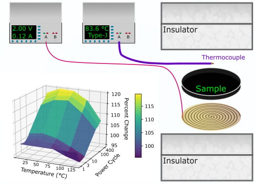
This study used a power cycling schema because it is best designed to simulate the real-world operating conditions of these materials. The procedure used in this study consisted of altering the temperature of the TIM between room temperature and an elevated temperature of 120 °C, a temperature range which encompasses the majority of applications of TIMs. This temperature change is achieved with a planar heat source. At set cycle counts, the samples’ thermal parameters were measured with a laser flash analysis instrument (LFA 467, Netzsch GmbH). Figure 1 illustrates the power cycling treatment procedure used. More details of this procedure can be found in the Methods section. Any impact of environmental humidity should be largely neutralized in this study due to the samples being cured and not bound to any surface.
4. Thermal Diffusivity and Conductivity of the Graphene Composites
The ultimate metric for the effectiveness of a TIM is the reduction in the thermal resistance of a physical junction that it is placed between (). is expressed by the following relationship:
where is the bond line thickness of the applied TIM, is the TIM’s thermal conductivity, and and are the contact resistances of the TIM at each of the junction’s adjoining surfaces [71]. The thermal conductivity of a material expresses the ability of that material to pass an amount of heat energy over a given distance and temperature gradient. It will be the primary metric of TIM performance considered in this study. Maximizing the thermal conductivity and minimizing the bond line thickness and contact resistances achieves a lower thermal resistance.
Alternative to the more classic TIM view presented just prior, thermosetting plastics are frequently used to coat electronics and protect them from environmental contamination but inadvertently introduce a substantial thermal resistance hindering the radiative and convective removal of heat into adjoining heat sinks or directly into the device chassis. In this case, the mathematical expression has only a single contact resistance component—between the chip and encapsulating TIM—and the thickness of the TIM is intentionally relatively thick, both factors often resulting in an even greater relative influence of thermal conductivity on the TIM’s thermal dissipative performance. The reduction in overall thermal resistance in chip packaging would result in a smaller temperature difference between the heat-producing chip and the outside surface of the attached TIM, resulting in more radiative heat flow and convective heat flow through air. In this case, the color and morphology of the outside surface become parameters in heat flow due to their impacts on the encasing emissivity and surface area for convective exchange. Of course, thermal energy in these chips is still passed through the electrical connections. However, this channel of dissipation is mostly unaffected by the polymeric TIM encasing.
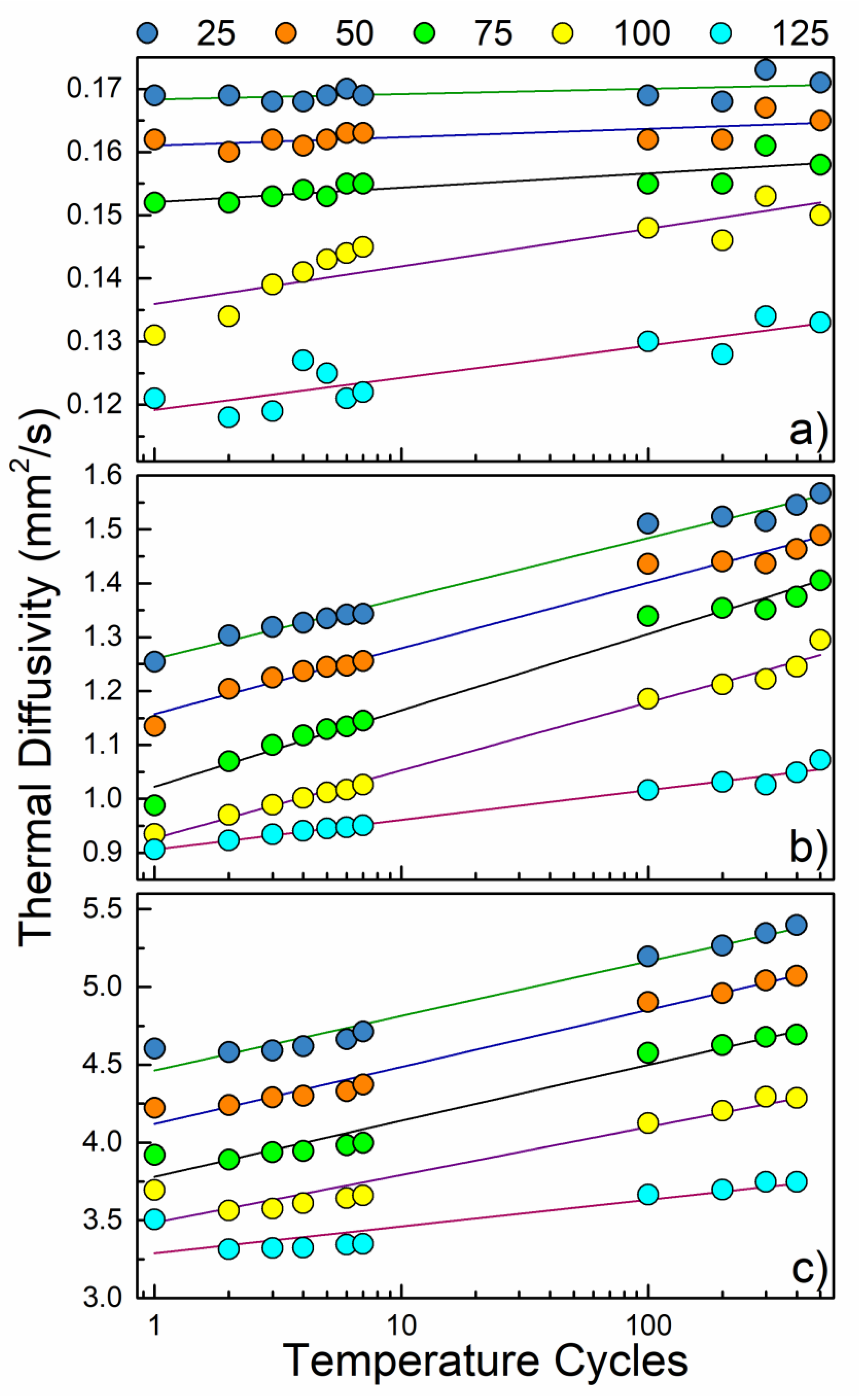
Thermal conductivity in this study was determined through the relationship , where is the thermal diffusivity, is the volumetric mass density, and is the heat capacity of a material. The heat capacity was calculated for each sample at each relevant temperature by the rule of mixtures using data from a differential scanning calorimetry (DSC 214 Polyma, Netzsch GmbH) experiment of a pure epoxy sample and heat capacities reported in the literature for graphite. It has been shown previously that the heat capacity of graphene and graphite only meaningfully deviate from one another below 100 K—well below temperatures considered at present—because of the existence of low-frequency ZA phonons in graphene, which contribute to the heat capacity of graphene [72,73]. The diffusivity was measured with a laser flash analysis instrument. In Figure 2, we present the evolution of the thermal diffusivity with power cycles.
The thermal diffusivities were measured for samples with graphene concentrations of 0 vol%, 5.4 vol%, and 30 vol% and are shown in Figure 2. One should note here that higher loadings of graphene, up to 45 vol%, have been achieved via a multistage loading process [17]. Here, we limited the loading fraction to 30 vol% to be more representative of the commonly studied graphene-enhanced composites. The room temperature (RT) thermal diffusivity of the samples was 0.17, 1.25, and 4.6 mm2s−1, respectively. The enhancement in the thermal diffusivity as the graphene loading changes from 0 vol% to 30 vol% constitutes a factor of ~27. At the end of power cycling treatments, RT thermal diffusivities of 0.17, 1.57, and 5.40 mm2/sec were recorded for 0 vol%, 5.4 vol%, and 30 vol%, respectively. This increase in diffusivity is a percentage increase of 0%, 25.6%, and 17.4% relative to their initial values. Supplemental Figure S1 provides a visualization for the improvement of the 30 vol% sample. After 400 cycles applied to the 30 vol% sample, the thermal diffusivity enhancement relative to 0 vol% would increase to ≈31.4 at RT. These results, in addition to the very modest changes in thermal diffusivity of the pure epoxy matrix over the full range of treatment cycles, suggest that the graphene fillers play an integral role in this observed behavior.
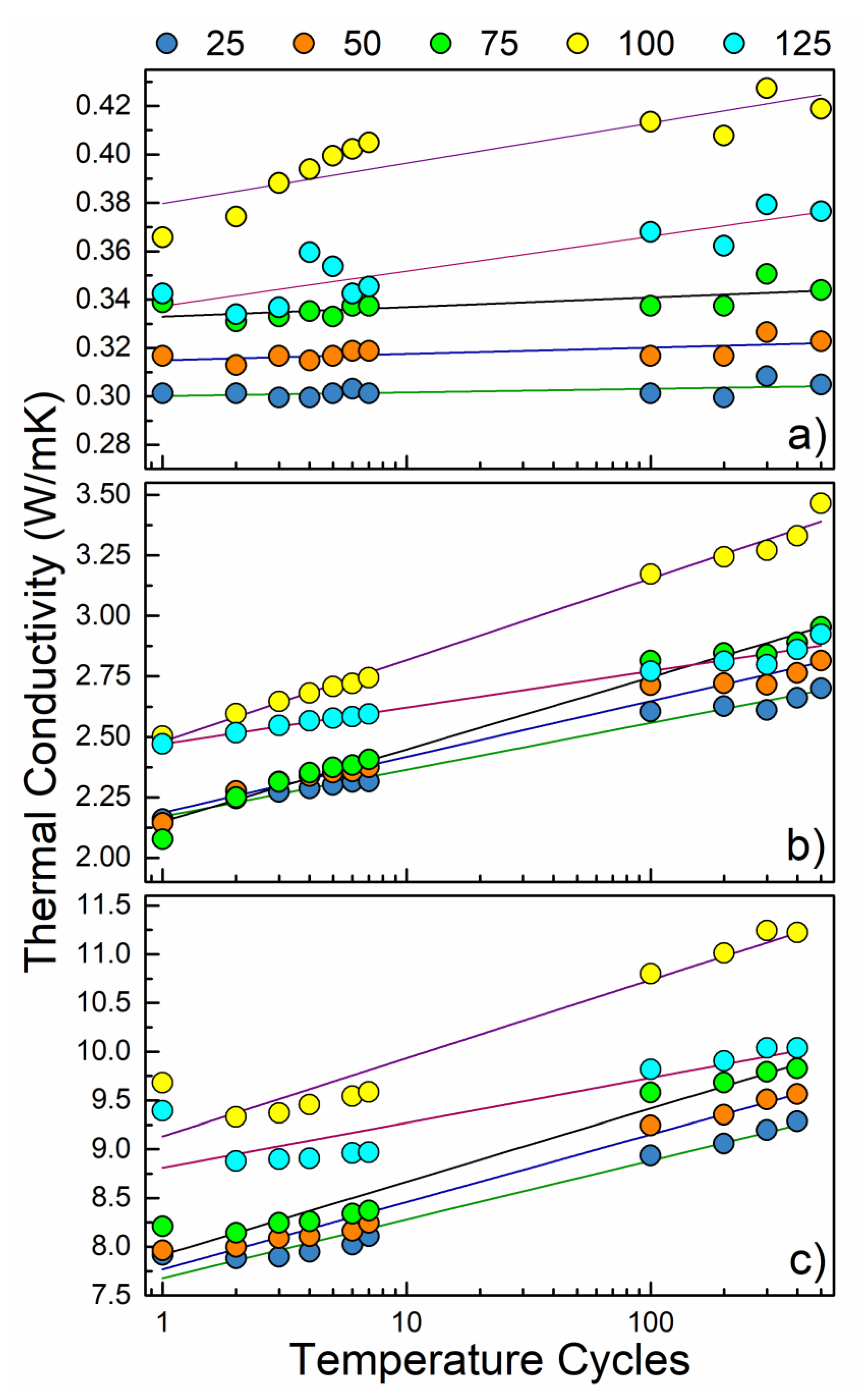
Figure 3 shows the thermal conductivities of the three tested samples. The mass densities of the pure epoxy composite with 5.4 vol% of graphene, and composite with 30 vol% loading of graphene were measured to be 1.18, 1.17, and 1.35 gcm−3, respectively. The mass density of the samples did not show noticeable changes during the course of power cycling. Impressively, after power cycling treatments, the 30 vol% sample achieved a RT thermal conductivity of 9.3 Wm−1K−1. This value is above that in commercially available TIMs and at the level of the highest reported for graphene enhanced TIMs [17,41]. The 0 vol% TIM sample’s enhancement in thermal conductivity at 100 °C was a modest 7.7%, from 0.39 to ≈0.42 Wm−1K−1 and did not display conclusive changes at other temperatures. In contrast, the 5.4 vol% and 30 vol% samples experienced strong enhancements in thermal conductivity over the course of treatment for all tested temperatures, achieving 24.9% and 17.3% improvements at room temperature, respectively. The thermal conductivity behavior with temperature is primarily influenced by the marked increase in composite heat capacity at increasing temperature. Detailed Raman and SEM inspection did not reveal any noticeable structural changes in the composites.
It is interesting to note that in each sample and at all temperature cycle counts, the thermal conductivities measured at 125 °C were lower than those measured at 100 °C, despite an otherwise uniform tendency for the thermal conductivity to increase with temperature. The failure of the increasing trend found in the lower-temperature regimen could be explained by experimenting past the glass transition temperature, at which point polymers are known to have degraded thermal transport properties, occurring in this epoxy around 100 °C [50,74]. It has been reported that the glass temperature of polymers can be raised through the inclusion inert materials, such as graphene [75,76]. In this instance, the elevation of the glass transition temperature would be substantially more modest than the 30 °C alteration seen previously in a poly-(methyl-methacrylate) matrix. Such an outcome would suggest that the graphene filler does not strongly inhibit the cross-linking of polymer chains such as Bisphenol-A [77,78]. The low dimensionality of graphene could allow for minimal reduction in cross-linking density.
5. Discussion
The obtained results show a clear enhancement in the performance of cured graphene TIMs over a realistic device lifespan isolated from an overall heat sink solution. Furthermore, it is evident that the performance improvement is greater than that of the pure epoxy sample control, especially at lower device temperatures. In a previous study, changes in the thermal resistance over the course of over 2000 temperature cycles were observed for multiple silver-filled epoxies. A significant decline in thermal transport performance was found when composites were bonded between surfaces of disparate coefficients of thermal expansion. In such cases, the increase in the thermal resistance was approximately a factor of nine [79]. These results and others like them should not be considered contradictory to the present findings due to the removal of all interfacial effects in the present study. In other studies, the behavior-altering mechanisms of thermal expansion mismatch and mechanical cracking are present but have been intentionally suppressed in this study by design. Due to the overwhelming contribution to the thermal resistance that TIM cracking and detachment can introduce, an intrinsic TIM behavior analysis of thermal conductivity is not possible or at least extremely challenging to determine in classical studies on the topic.
In another report, a pure epoxy adhesive TIM displayed thermal resistance reductions of 8% [44]. The observed slight reduction in the epoxy TIM thermal resistance was tentatively attributed to increased epoxy cross-linking. In our measurements, any improvement in the thermal conductivity of pure epoxy is inconclusive; there is only a small alteration over 100 °C and there is no noteworthy change below that temperature. The present results for pure epoxy are largely in agreement with the very modest reductions in thermal resistance of pure epoxy TIMs seen previously. However, upon the inclusion of graphene into the epoxy matrix, a clear increase in RT thermal conductivity over the course of power cycling treatments of 24.9% in 5.4 vol% and 17.3% in 30 vol% is observed. It is evident from these present results that graphene plays an integral role in the observed enhancement in power cycling treatments.
It is proposed that the mechanism of enhancement of thermal conductivity is indeed increased epoxy cross-linking at elevated temperatures, resulting in more tightly bound graphene to the more rigid polymer matrix. In this case, the length of the polymer molecules would increase, pressing increasingly upon the already dispersed graphene fillers. Likely aiding this process is the polymer matrix exhibiting thermal expansion owing to the treatment procedure, passing its glass transition temperature, pressing polymer molecules and graphene flakes closer together and cross-linking permanently in that position [76]. This would increase the vibrational coupling between the polymer matrix and the graphene fillers, allowing for better transfer of the lattice vibrations between graphene and the polymer matrix. In other words, the microscopic interfacial Kapitza [80] resistance of internal TIM components is decreased by time spent at elevated temperature. This proposed mechanism of enhancement would likely be highly dependent on the geometry of the filler material used.
There is little consistency in the literature that one could use to draw definite conclusions about performance of TIMs in accelerated aging studies. This can be attributed to different testing protocols and different materials examined. Previously, a universal tendency for the thermal resistance of all tested low-melting-temperature alloy TIMs comprising indium, gallium, bismuth, and tin between copper, nickel, and tungsten surfaces to modestly increase with isothermal elevated temperature treatment aging (HTS and TC methods) was shown, signifying at least a slight reduction in performance [49]. Some prior studies demonstrated substantial changes in the thermal resistance of phase change TIMs after power cycling over 10,000 times. Interestingly, the lack of any notable degradation of this TIM material over the examined cycles was attributed to the material’s ability to re-conform to the thermal interface during melting and solidifying processes [67]. A similar reliability study on phase change material TIMs showed little change in thermal impedance over 2000 cycles [68]. Another study also examined the thermal interface resistance of a similar, graphene-filled epoxy cycled in a temperature range between 27 and 97 °C—a cycling process below glass transition of the matrix at all times—and found no noteworthy changes, even when tested over only 10 full cycles [50]. In light of the inconsistency in the reported data, briefly sampled just prior, even amongst studies of similar TIM materials, a more simplified approach in which the isolation of individual parameters of the TIM was used [6]. By negating any effect of interfacial resistance, we were able to directly analyze the thermal conductivity TIM parameter with confidence. Simplification of the power cycling-accelerated aging schema and resultant isolation of parameters of interest could be an effective method to increase the consistency among similar future studies. The isolation of the changes in the thermal conductivity from any potential changes in the contact resistances allows for a direct observation of the salient contributing factors to thermal resistance. The latter is unfeasible in more conventional lifespan TIM performance studies.
6. Conclusions
We reported the results of the first reliability study of epoxy matrix TIMs loaded with graphene fillers over the course of a realistic device lifespan. The systematic testing of the graphene-enhanced TIMs confirms their potential for practical applications in thermal management. Moreover, it was found, unexpectedly, that the thermal conductivity of graphene epoxy TIMs improves over the course of cycling. The obtained results clearly show an increase in the thermal diffusivity and conductivity of cured graphene and epoxy polymer composites over the course of up to 500 thermal cycle treatments, reaching an enhancement of up to ≈25%. In contrast, the reference sample-pure Bisphenol-A epoxy—only received a modest enhancement in thermal conductivity when at elevated temperatures (≥100 °C) of ≈7.7%. The graphene-loaded samples displayed enhanced thermal diffusivity and conductivity behaviors at all temperatures, importantly including room temperature. It is suggested that the mechanism for this marked enhancement in thermal conductivity of graphene-epoxy composites is related to increased cross-linking, resulting in graphene being better coupled to the polymer matrix.
Supplementary Materials
The following are available online at https://0-www-mdpi-com.brum.beds.ac.uk/2311-5629/6/2/26/s1, Figure S1: A three-dimensional visualization of the thermal diffusivity enhancement in the 30 vol% composite, Figure S2: A SEM micrograph of a fractured surface of a 5.4 vol% composite, Figure S3: Raman spectrum of a 5.4 vol% composite, Figure S4: Differential scanning calorimetry experimental results of our pure epoxy matrix, and Figure S5: Plot of temperature over time for the power cycling procedure.
Author Contributions
A.A.B. coordinated the project and contributed to the experimental and theoretical data analysis. J.S.L. designed the testing protocols, built the experimental setup, synthesized composites, and conducted thermal conductivity measurements and thermal cycling tests. T.P. assisted with sample preparation and thermal measurements and conducted thermal cycling tests. A.M. conducted material characterization and assisted with measurements. F.K. contributed to the testing protocol design and thermal data analysis. All authors contributed to the manuscript preparation. All authors have read and agreed to the published version of the manuscript.
Funding
The work at UCR was supported, in part, by the Office of Technology Partnerships (OTP), University of California via the Proof of Concept (POC) project “Graphene Thermal Interface Materials.” A.A.B. also acknowledges the UC—National Laboratory Collaborative Research and Training Program—University of California Research Initiatives LFR-17-477237.
Conflicts of Interest
The authors declare no conflict of interest.
References
- Trew, R.; Green, D.; Shealy, J. AlGaN/GaN HFET Reliability. IEEE Microw. Mag. 2009, 10, 116–127. [Google Scholar] [CrossRef]
- Saadah, M.; Hernandez, E.; Balandin, A.A. Thermal Management of Concentrated Multi-Junction Solar Cells with Graphene-Enhanced Thermal Interface Materials. Appl. Sci. 2017, 7, 589. [Google Scholar] [CrossRef] [Green Version]
- Biber, C. LED Light Emission as a Function of Thermal Conditions. In Proceedings of the Annual IEEE Semiconductor Thermal Measurement and Management Symposium, San Jose, CA, USA, 16–20 March 2008; pp. 180–184. [Google Scholar] [CrossRef]
- Prasher, R. Thermal Interface Materials: Historical Perspective, Status, and Future Directions. Proc. IEEE 2006, 94, 1571–1586. [Google Scholar] [CrossRef]
- Chung, D.D.L. Thermal Interface Materials. J. Mater. Eng. Perform. 2001, 10, 56–59. [Google Scholar] [CrossRef]
- Due, J.; Robinson, A.J. Reliability of Thermal Interface Materials: A Review. Appl. Therm. Eng. 2013, 50, 455–463. [Google Scholar] [CrossRef]
- Deppisch, C.; Fitzgerald, T.; Raman, A.; Hua, F.; Zhang, C.; Liu, P.; Miller, M. The Material Optimization and Reliability Characterization of an Indium-Solder Thermal Interface Material for CPU Packaging. JOM 2006, 58, 67–74. [Google Scholar] [CrossRef]
- Narumanchi, S.; Mihalic, M.; Kelly, K.; Eesley, G. Thermal Interface Materials for Power Electronics Applications. In Proceedings of the 2008 11th Intersociety Conference on Thermal and Thermomechanical Phenomena in Electronic Systems, Orlando, FL, USA, 28–31 May 2008; pp. 395–404. [Google Scholar] [CrossRef]
- Prasher, R.S. Surface Chemistry and Characteristics Based Model for the Thermal Contact Resistance of Fluidic Interstitial Thermal Interface Materials. J. Heat Transfer 2001, 123, 969–975. [Google Scholar] [CrossRef]
- Prasher, R.S.; Matayabas, J.C. Thermal Contact Resistance of Cured Gel Polymeric Thermal Interface Material. IEEE Trans. Compon. Packag. Technol. 2004, 27, 702–709. [Google Scholar] [CrossRef]
- Yu, A.; Ramesh, P.; Itkis, M.E.; Bekyarova, E.; Haddon, R.C. Graphite Nanoplatelet−Epoxy Composite Thermal Interface Materials. J. Phys. Chem. C 2007, 111. [Google Scholar] [CrossRef]
- Xu, J.; Fisher, T.S. Enhancement of Thermal Interface Materials with Carbon Nanotube Arrays. Int. J. Heat Mass Transf. 2006, 49, 1658–1666. [Google Scholar] [CrossRef]
- Tong, T.; Zhao, Y.; Delzeit, L.; Kashani, A.; Meyyappan, M.; Majumdar, A. Dense Vertically Aligned Multiwalled Carbon Nanotube Arrays as Thermal Interface Materials. IEEE Trans. Compon. Packag. Technol. 2007, 30, 92–100. [Google Scholar] [CrossRef]
- Lin, C.; Chung, D.D.L. Graphite Nanoplatelet Pastes vs. Carbon Black Pastes as Thermal Interface Materials. Carbon 2009, 47, 295–305. [Google Scholar] [CrossRef]
- Yu, H.; Li, L.; Kido, T.; Xi, G.; Xu, G.; Guo, F. Thermal and Insulating Properties of Epoxy/Aluminum Nitride Composites Used for Thermal Interface Material. J. Appl. Polym. Sci. 2012, 124, 669–677. [Google Scholar] [CrossRef]
- Uetani, K.; Ata, S.; Tomonoh, S.; Yamada, T.; Yumura, M.; Hata, K. Elastomeric Thermal Interface Materials with High Through-Plane Thermal Conductivity from Carbon Fiber Fillers Vertically Aligned by Electrostatic Flocking. Adv. Mater. 2014, 26, 5857–5862. [Google Scholar] [CrossRef]
- Kargar, F.; Barani, Z.; Salgado, R.; Debnath, B.; Lewis, J.S.; Aytan, E.; Lake, R.K.; Balandin, A.A. Thermal Percolation Threshold and Thermal Properties of Composites with High Loading of Graphene and Boron Nitride Fillers. ACS Appl. Mater. Interfaces 2018, 10, 37555–37565. [Google Scholar] [CrossRef]
- Shtein, M.; Nadiv, R.; Buzaglo, M.; Regev, O. Graphene-Based Hybrid Composites for Efficient Thermal Management of Electronic Devices. ACS Appl. Mater. Interfaces 2015, 7, 23725–23730. [Google Scholar] [CrossRef]
- Lewis, J.S.; Barani, Z.; Magana, A.S.; Kargar, F.; Balandin, A.A. Thermal and Electrical Conductivity Control in Hybrid Composites with Graphene and Boron Nitride Fillers. Mater. Res. Express 2019, 6, 085325. [Google Scholar] [CrossRef] [Green Version]
- Chun, K.-Y.; Oh, Y.; Rho, J.; Ahn, J.-H.; Kim, Y.-J.; Choi, H.R.; Baik, S. Highly Conductive, Printable and Stretchable Composite Films of Carbon Nanotubes and Silver. Nat. Nanotechnol. 2010, 5, 853–857. [Google Scholar] [CrossRef]
- Zhou, T.; Wang, X.; Liu, X.; Xiong, D. Improved Thermal Conductivity of Epoxy Composites Using a Hybrid Multi-Walled Carbon Nanotube/Micro-SiC Filler. Carbon 2010, 48, 1171–1176. [Google Scholar] [CrossRef]
- Ma, P.-C.; Liu, M.-Y.; Zhang, H.; Wang, S.-Q.; Wang, R.; Wang, K.; Wong, Y.-K.; Tang, B.-Z.; Hong, S.-H.; Paik, K.-W.; et al. Enhanced Electrical Conductivity of Nanocomposites Containing Hybrid Fillers of Carbon Nanotubes and Carbon Black. ACS Appl. Mater. Interfaces 2009, 1, 1090–1096. [Google Scholar] [CrossRef]
- Li, H.; Dai, S.; Miao, J.; Wu, X.; Chandrasekharan, N.; Qiu, H.; Yang, J. Enhanced Thermal Conductivity of Graphene/Polyimide Hybrid Film via a Novel “Molecular Welding” Strategy. Carbon 2018, 126, 319–327. [Google Scholar] [CrossRef]
- Teng, C.-C.; Ma, C.-C.M.; Chiou, K.-C.; Lee, T.-M. Synergetic Effect of Thermal Conductive Properties of Epoxy Composites Containing Functionalized Multi-Walled Carbon Nanotubes and Aluminum Nitride. Compos. Part B Eng. 2012, 43, 265–271. [Google Scholar] [CrossRef]
- Choi, S.; Im, H.; Kim, J. Flexible and High Thermal Conductivity Thin Films Based on Polymer: Aminated Multi-Walled Carbon Nanotubes/Micro-Aluminum Nitride Hybrid Composites. Compos. Part A Appl. Sci. Manuf. 2012, 43, 1860–1868. [Google Scholar] [CrossRef]
- Choi, S.; Kim, J. Thermal Conductivity of Epoxy Composites with a Binary-Particle System of Aluminum Oxide and Aluminum Nitride Fillers. Compos. Part B Eng. 2013, 51, 140–147. [Google Scholar] [CrossRef]
- Zhou, W.; Wang, C.; An, Q.; Ou, H. Thermal Properties of Heat Conductive Silicone Rubber Filled with Hybrid Fillers. J. Compos. Mater. 2008, 42, 173–187. [Google Scholar] [CrossRef]
- Barani, Z.; Mohammadzadeh, A.; Geremew, A.; Huang, C.; Coleman, D.; Mangolini, L.; Kargar, F.; Balandin, A.A. Thermal Properties of the Binary-Filler Hybrid Composites with Graphene and Copper Nanoparticles. Adv. Funct. Mater. 2019, 1904008. [Google Scholar] [CrossRef]
- Balandin, A.A.; Ghosh, S.; Bao, W.; Calizo, I.; Teweldebrhan, D.; Miao, F.; Lau, C.N. Superior Thermal Conductivity of Single-Layer Graphene. Nano Lett. 2008, 8, 902–907. [Google Scholar] [CrossRef]
- Balandin, A.A. Thermal Properties of Graphene and Nanostructured Carbon Materials. Nat. Mater. 2011, 10, 569–581. [Google Scholar] [CrossRef] [Green Version]
- Ghosh, S.; Calizo, I.; Teweldebrhan, D.; Pokatilov, E.P.; Nika, D.L.; Balandin, A.A.; Bao, W.; Miao, F.; Lau, C.N. Extremely High Thermal Conductivity of Graphene: Prospects for Thermal Management Applications in Nanoelectronic Circuits. Appl. Phys. Lett. 2008, 92, 151911. [Google Scholar] [CrossRef]
- Seol, J.H.; Jo, I.; Moore, A.L.; Lindsay, L.; Aitken, Z.H.; Pettes, M.T.; Li, X.; Yao, Z.; Huang, R.; Broido, D.; et al. Two-Dimensional Phonon Transport in Supported Graphene. Science 2010, 328, 213–216. [Google Scholar] [CrossRef] [Green Version]
- Cai, W.; Moore, A.L.; Zhu, Y.; Li, X.; Chen, S.; Shi, L.; Ruoff, R.S. Thermal Transport in Suspended and Supported Monolayer Graphene Grown by Chemical Vapor Deposition. Nano Lett. 2010, 10, 1645–1651. [Google Scholar] [CrossRef] [PubMed]
- Shahil, K.M.F.; Balandin, A.A. Graphene–Multilayer Graphene Nanocomposites as Highly Efficient Thermal Interface Materials. Nano Lett. 2012, 12, 861–867. [Google Scholar] [CrossRef] [PubMed] [Green Version]
- Renteria, J.; Legedza, S.; Salgado, R.; Balandin, M.P.; Ramirez, S.; Saadah, M.; Kargar, F.; Balandin, A.A. Magnetically-Functionalized Self-Aligning Graphene Fillers for High-Efficiency Thermal Management Applications. Mater. Des. 2015, 88, 214–221. [Google Scholar] [CrossRef] [Green Version]
- Dmitriev, A.S.; Valeev, A.R. Graphene Nanocomposites as Thermal Interface Materials for Cooling Energy Devices. J. Phys. Conf. Ser. 2017, 891, 012359. [Google Scholar] [CrossRef] [Green Version]
- Tang, B.; Hu, G.; Gao, H.; Hai, L. Application of Graphene as Filler to Improve Thermal Transport Property of Epoxy Resin for Thermal Interface Materials. Int. J. Heat Mass Transf. 2015, 85, 420–429. [Google Scholar] [CrossRef]
- Yan, Z.; Liu, G.; Khan, J.M.; Balandin, A.A. Graphene Quilts for Thermal Management of High-Power GaN Transistors. Nat. Commun. 2012, 3, 827. [Google Scholar] [CrossRef]
- Naghibi, S.; Kargar, F.; Wright, D.; Huang, C.Y.T.; Mohammadzadeh, A.; Barani, Z.; Salgado, R.; Balandin, A.A. Noncuring Graphene Thermal Interface Materials for Advanced Electronics. Adv. Electron. Mater. 2020, 1901303. [Google Scholar] [CrossRef]
- Mahadevan, B.K.; Naghibi, S.; Kargar, F.; Balandin, A.A. Non-Curing Thermal Interface Materials with Graphene Fillers for Thermal Management of Concentrated Photovoltaic Solar Cells. C J. Carbon Res. 2019, 6, 2. [Google Scholar] [CrossRef] [Green Version]
- Kargar, F.; Barani, Z.; Balinskiy, M.; Magana, A.S.; Lewis, J.S.; Balandin, A.A. Dual-Functional Graphene Composites for Electromagnetic Shielding and Thermal Management. Adv. Electron. Mater. 2018, 1800558. [Google Scholar] [CrossRef] [Green Version]
- Kargar, F.; Salgado, R.; Legedza, S.; Renteria, J.; Balandin, A.A. A Comparative Study of the Thermal Interface Materials with Graphene and Boron Nitride Fillers; Razeghi, M., Lee, Y.H., Ghazinejad, M., Eds.; International Society for Optics and Photonics: San Diego, CA, USA, 2014; Volume 9168, p. 91680S. [Google Scholar] [CrossRef]
- Li, J.; Myllykoski, P.; Paulasto-Krockel, M. Study on Thermomechanical Reliability of Power Modules and Thermal Grease Pump-out Mechanism. In Proceedings of the 2015 16th International Conference on Thermal, Mechanical and Multi-Physics Simulation and Experiments in Microelectronics and Microsystems, EuroSimE 2015, Budapest, Hungary, 19–22 April 2015; Institute of Electrical and Electronics Engineers Inc.: New York, NY, USA, 2015. [Google Scholar] [CrossRef]
- Khuu, V.; Osterman, M.; Bar-Cohen, A.; Pecht, M. Effects of Temperature Cycling and Elevated Temperature/Humidity on the Thermal Performance of Thermal Interface Materials. IEEE Trans. Device Mater. Reliab. 2009, 9, 379–391. [Google Scholar] [CrossRef]
- Gowda, A.; Esler, D.; Paisner, S.N.; Tonapi, S.; Nagarkar, K.; Srihari, K. Reliability Testing of Silicone-Based Thermal Greases. In Proceedings of the Annual IEEE Semiconductor Thermal Measurement and Management Symposium, San Jose, CA, USA, 15–17 March 2005; pp. 64–71. [Google Scholar] [CrossRef]
- Chen, C.I.; Ni, C.Y.; Pan, H.Y.; Chang, C.M.; Liu, D.S. Practical Evaluation For Long-term Stability of Thermal Interface Material. Exp. Tech. 2009, 33, 28–32. [Google Scholar] [CrossRef]
- Chiu, C.P.; Chandran, B.; Mello, M.; Kelley, K. An Accelerated Reliability Test Method to Predict Thermal Grease Pump-out in Flip-Chip Applications. Proc. Electron. Compon. Technol. Conf. 2001, 91–97. [Google Scholar] [CrossRef]
- Wang, T.H.; Chen, H.Y.; Lee, C.C.; Lai, Y.S. High-Power-Used Thermal Gel Degradation Evaluation on Board-Level HFCBGA Subjected to Reliability Tests. In Proceedings of the 2009 4th International Microsystems, Packaging, Assembly and Circuits Technology Conference, Taipei, Taiwan, 21–23 October 2009; pp. 465–468. [Google Scholar] [CrossRef]
- Roy, C.K.; Bhavnani, S.; Hamilton, M.C.; Johnson, R.W.; Knight, R.W.; Harris, D.K. Accelerated Aging and Thermal Cycling of Low Melting Temperature Alloys as Wet Thermal Interface Materials. Microelectron. Reliab. 2015, 55, 2698–2704. [Google Scholar] [CrossRef]
- Park, W.; Guo, Y.; Li, X.; Hu, J.; Liu, L.; Ruan, X.; Chen, Y.P. High-Performance Thermal Interface Material Based on Few-Layer Graphene Composite. J. Phys. Chem. C 2015, 119, 26753–26759. [Google Scholar] [CrossRef] [Green Version]
- Skuriat, R.; Li, J.F.; Agyakwa, P.A.; Mattey, N.; Evans, P.; Johnson, C.M. Degradation of Thermal Interface Materials for High-Temperature Power Electronics Applications. Microelectron. Reliab. 2013, 53, 1933–1942. [Google Scholar] [CrossRef]
- Nylander, A.; Hansson, J.; Kabiri Samani, M.; Chandra Darmawan, C.; Borta Boyon, A.; Divay, L.; Ye, L.; Fu, Y.; Ziaei, A.; Liu, J. Reliability Investigation of a Carbon Nanotube Array Thermal Interface Material. Energies 2019, 12, 2080. [Google Scholar] [CrossRef] [Green Version]
- Ferrari, A.C. Raman Spectroscopy of Graphene and Graphite: Disorder, Electron–Phonon Coupling, Doping and Nonadiabatic Effects. Solid State Commun. 2007, 143, 47–57. [Google Scholar] [CrossRef]
- Ferrari, A.C.; Basko, D.M. Raman Spectroscopy as a Versatile Tool for Studying the Properties of Graphene. Nat. Nanotechnol. 2013, 8, 235–246. [Google Scholar] [CrossRef] [Green Version]
- Calizo, I.; Bao, W.; Miao, F.; Lau, C.N.; Balandin, A.A. The effect of substrates on the Raman spectrum of graphene: Graphene-on-sapphire and graphene-on-glass. Appl. Phys. Lett. 2007, 91, 201904. [Google Scholar] [CrossRef]
- Calizo, I.; Miao, F.; Bao, W.; Lau, C.N.; Balandin, A.A. Variable temperature Raman microscopy as a nanometrology tool for graphene layers and graphene-based devices. Appl. Phys. Lett. 2007, 91, 71913. [Google Scholar] [CrossRef] [Green Version]
- Parvizi, F.; Teweldebrhan, D.; Ghosh, S.; Calizo, I.; Balandin, A.A.; Zhu, H.; Abbaschian, R. Properties of graphene produced by the high pressure–high temperature growth process. Micro Nano Lett. 2008, 3, 29. [Google Scholar] [CrossRef] [Green Version]
- Plazek, D.J.; Choy, I.C. The Physical Properties of Bisphenol-a-Based Epoxy Resins during and after Curing. II. Creep Behavior above and below the Glass Transition Temperature. J. Polym. Sci. Part B Polym. Phys. 1989, 27, 307–324. [Google Scholar] [CrossRef]
- DGEBA Epoxy Resin. Available online: https://polymerdatabase.com/polymers/bisphenol-adiglycidyletherepoxyresin.html (accessed on 5 January 2020).
- Goel, N.; Anoop, T.K.; Bhattacharya, A.; Cervantes, J.A.; Mongia, R.K.; Machiroutu, S.V.; Lin, H.L.; Huang, Y.C.; Fan, K.C.; Denq, B.L.; et al. Technical Review of Characterization Methods for Thermal Interface Materials (TIM). In Proceedings of the 2008 11th IEEE Intersociety Conference on Thermal and Thermomechanical Phenomena in Electronic Systems, I-THERM, Orlando, FL, USA, 28–31 May 2008; pp. 248–258. [Google Scholar] [CrossRef]
- Parker, W.J.; Jenkins, R.J.; Butler, C.P.; Abbott, G.L. Flash Method of Determining Thermal Diffusivity, Heat Capacity, and Thermal Conductivity. J. Appl. Phys. 1961, 32, 1679–1684. [Google Scholar] [CrossRef]
- Liu, W.L.; Shamsa, M.; Calizo, I.; Balandin, A.A.; Ralchenko, V.; Popovich, A.; Saveliev, A. Thermal Conduction in Nanocrystalline Diamond Films: Effects of the Grain Boundary Scattering and Nitrogen Doping. Appl. Phys. Lett. 2006, 89, 171915. [Google Scholar] [CrossRef] [Green Version]
- Balandin, A.A.; Shamsa, M.; Liu, W.L.; Casiraghi, C.; Ferrari, A.C. Thermal Conductivity of Ultrathin Tetrahedral Amorphous Carbon Films. Appl. Phys. Lett. 2008, 93, 043115. [Google Scholar] [CrossRef]
- Ghosh, S.; Teweldebrhan, D.; Morales, J.R.; Garay, J.E.; Balandin, A.A. Thermal Properties of the Optically Transparent Pore-Free Nanostructured Yttria-Stabilized Zirconia. J. Appl. Phys. 2009, 106, 113507. [Google Scholar] [CrossRef] [Green Version]
- Shamsa, M.; Liu, W.L.; Balandin, A.A.; Casiraghi, C.; Milne, W.I.; Ferrari, A.C. Thermal conductivity of diamond-like carbon films. Appl. Phys. Lett. 2006, 89, 161921. [Google Scholar] [CrossRef] [Green Version]
- Dal, S.L.B. Degradation Mechanisms of Siloxane-Based Thermal Interface Materials under Reliability Stress Conditions. In Proceedings of the IEEE International Reliability Physics Symposium Proceedings, Phoenix, AZ, USA, 25–29 April 2004; Institute of Electrical and Electronics Engineers Inc.: New York, NY, USA, 2004; Volume 2004, pp. 537–542. [Google Scholar] [CrossRef]
- Bharatham, L.; Wong, S.F.; Torresola, J.; Chen, C.K. Qualification of Phase Change Thermal Interface Material for Wave Solder Heat Sink on FCBGA Package. In Proceedings of the 7th Electronics Packaging Technology Conference, EPTC 2005, Singapore, 7–9 December 2005; Volume 2, pp. 537–542. [Google Scholar] [CrossRef]
- Ramaswamy, C.; Shinde, S.; Pompeo, F.; Sablinski, W.; Bradley, S. Phase Change Materials as a Viable Thermal Interface Material for High-Power Electronic Applications. In Proceedings of the Thermomechanical Phenomena in Electronic Systems -Proceedings of the Intersociety Conference, Las Vegas, NV, USA, 1–4 June 2004; Volume 2, pp. 687–691. [Google Scholar] [CrossRef]
- Paisner, S.N.; Touzelbaev, M.; Refai-Ahmed, G.; Yang, Y. New Developments for a No-Pump-out High-Performance Thermal Grease. In Proceedings of the 2010 12th IEEE Intersociety Conference on Thermal and Thermomechanical Phenomena in Electronic Systems, ITherm 2010, Las Vegas, NV, USA, 2–5 June 2010. [Google Scholar] [CrossRef]
- Gowda, A.; Zhong, A.; Esler, D.; David, J.; Sandeep, T.; Srihari, K.; Schattenmann, F. Design of a High Reliability and Low Thermal Resistance Interface Material for Microelectronics. In Proceedings of the 5th Electronics Packaging Technology Conference, EPTC 2003, Singapore, 12 December 2003; Institute of Electrical and Electronics Engineers Inc.: New York, NY, USA, 2003; pp. 557–562. [Google Scholar] [CrossRef]
- Prasher, R.S.; Shipley, J.; Prstic, S.; Koning, P.; Wang, J. Thermal Resistance of Particle Laden Polymeric Thermal Interface Materials. J. Heat Transfer. 2003, 125, 1170–1177. [Google Scholar] [CrossRef]
- Nika, D.L.; Cocemasov, A.I.; Balandin, A.A. Specific Heat of Twisted Bilayer Graphene: Engineering Phonons by Atomic Plane Rotations. Appl. Phys. Lett. 2014, 105, 031904. [Google Scholar] [CrossRef]
- Cocemasov, A.I.; Nika, D.L.; Balandin, A.A. Engineering of the Thermodynamic Properties of Bilayer Graphene by Atomic Plane Rotations: The Role of the out-of-Plane Phonons. Nanoscale 2015, 7, 12851–12859. [Google Scholar] [CrossRef] [Green Version]
- Dos Santos, W.N.; De Sousa, J.A.; Gregorio, R. Thermal Conductivity Behaviour of Polymers around Glass Transition and Crystalline Melting Temperatures. Polym. Test. 2013, 32, 987–994. [Google Scholar] [CrossRef] [Green Version]
- Ramanathan, T.; Abdala, A.A.; Stankovich, S.; Dikin, D.A.; Herrera-Alonso, M.; Piner, R.D.; Adamson, D.H.; Schniepp, H.C.; Chen, X.; Ruoff, R.S.; et al. Functionalized Graphene Sheets for Polymer Nanocomposites. Nat. Nanotechnol. 2008, 3, 327–331. [Google Scholar] [CrossRef] [PubMed]
- Yasmin, A.; Daniel, I.M. Mechanical and Thermal Properties of Graphite Platelet/Epoxy Composites. Polymer 2004, 45, 8211–8219. [Google Scholar] [CrossRef]
- Bansal, A.; Yang, H.; Li, C.; Cho, K.; Benicewicz, B.C.; Kumar, S.K.; Schadler, L.S. Quantitative Equivalence between Polymer Nanocomposites and Thin Polymer Films. Nat. Mater. 2005, 4, 693–698. [Google Scholar] [CrossRef]
- Rittigstein, P.; Priestley, R.D.; Broadbelt, L.J.; Torkelson, J.M. Model Polymer Nanocomposites Provide an Understanding of Confinement Effects in Real Nanocomposites. Nat. Mater. 2007, 6, 278–282. [Google Scholar] [CrossRef]
- Bjorneklett, A.; Tuhus, T.; Halbo, L.; Kristiansen, H. Thermal Resistance, Thermomechanical Stress and Thermal Cycling Endurance of Silicon Chips Bonded with Adhesives. In Proceedings of the Ninth Annual IEEE Semiconductor Thermal Measurement and Management Symposium, Austin, TX, USA, 2–4 February 1993; pp. 136–143. [Google Scholar] [CrossRef]
- Kapitza, P.L. The Study of Heat Transfer in Helium II. J. Phys. 1941, 4, 181. [Google Scholar]
Figure 1.
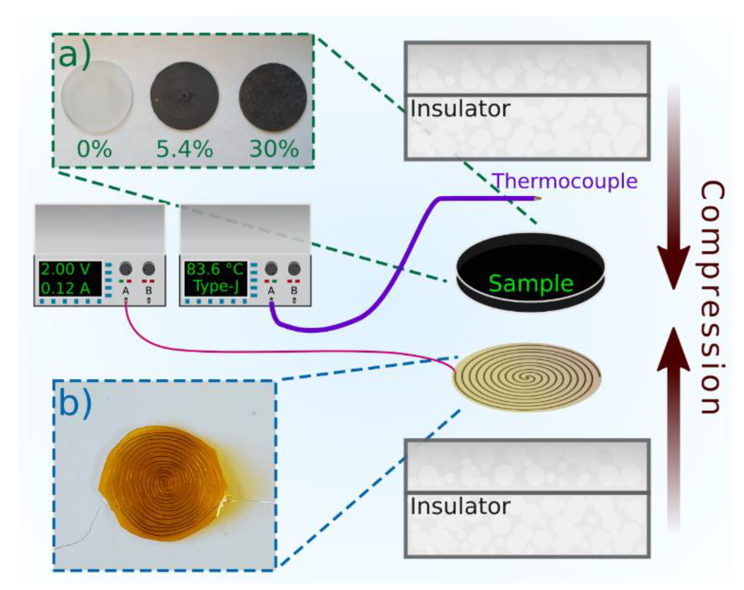
Simplified schematic of the temperature treatment experiment. A custom heating coil through which a current is passed is placed beneath the sample undergoing treatment. As a temperature feedback element, a Type-J thermocouple is used on the opposing surface of the sample to track its temperature. These are all then clamped under light compression between two thermal insulator materials. (a) Image of selected samples used in study. (b) Image of the custom heating element.
Figure 1.
Simplified schematic of the temperature treatment experiment. A custom heating coil through which a current is passed is placed beneath the sample undergoing treatment. As a temperature feedback element, a Type-J thermocouple is used on the opposing surface of the sample to track its temperature. These are all then clamped under light compression between two thermal insulator materials. (a) Image of selected samples used in study. (b) Image of the custom heating element.

Figure 2.
Thermal diffusivity for (a) pure epoxy matrix, (b) thermal interface materials (TIMs) with 5.4 vol% loading of graphene fillers, and (c) 30 vol% loading of graphene fillers. In each of the three samples, the measurements conducted at 25 °C resulted in the highest diffusivities. Additionally, increasing the number of heat treatment cycles either enhanced the thermal diffusivities or, in the case of the pure sample, had little to no effect depending on the temperature studied.

Figure 3.
Thermal conductivity of (a) pure epoxy matrix, (b) TIMs with 5.4 vol% loading of graphene fillers, and (c) TIMs with 30 vol% loading of graphene fillers.
Figure 3.
Thermal conductivity of (a) pure epoxy matrix, (b) TIMs with 5.4 vol% loading of graphene fillers, and (c) TIMs with 30 vol% loading of graphene fillers.

© 2020 by the authors. Licensee MDPI, Basel, Switzerland. This article is an open access article distributed under the terms and conditions of the Creative Commons Attribution (CC BY) license (http://creativecommons.org/licenses/by/4.0/).
Share and Cite
MDPI and ACS Style
Lewis, J.S.; Perrier, T.; Mohammadzadeh, A.; Kargar, F.; Balandin, A.A. Power Cycling and Reliability Testing of Epoxy-Based Graphene Thermal Interface Materials. C 2020, 6, 26. https://0-doi-org.brum.beds.ac.uk/10.3390/c6020026
AMA Style
Lewis JS, Perrier T, Mohammadzadeh A, Kargar F, Balandin AA. Power Cycling and Reliability Testing of Epoxy-Based Graphene Thermal Interface Materials. C. 2020; 6(2):26. https://0-doi-org.brum.beds.ac.uk/10.3390/c6020026
Chicago/Turabian StyleLewis, Jacob S., Timothy Perrier, Amirmahdi Mohammadzadeh, Fariborz Kargar, and Alexander A. Balandin. 2020. "Power Cycling and Reliability Testing of Epoxy-Based Graphene Thermal Interface Materials" C 6, no. 2: 26. https://0-doi-org.brum.beds.ac.uk/10.3390/c6020026
Note that from the first issue of 2016, this journal uses article numbers instead of page numbers. See further details here.