In Situ Formation of Metal Hydrides Inside Carbon Aerogel Frameworks for Hydrogen Storage Applications


1
School of Chemical and Bioprocess Engineering, University College Dublin, Belfield, Dublin 4, Ireland
2
Department of Civil and Environmental Engineering, K.N. Toosi University of Technology, Vali Asr Street, Tehran 19967-15433, Iran
3
Dipartimento di Scienza Dei Materiali, Universita di Milano Bicocca, Via Cozzi 55, 20125 Milano, Italy
*
Authors to whom correspondence should be addressed.
C 2020, 6(2), 38; https://0-doi-org.brum.beds.ac.uk/10.3390/c6020038
Submission received: 4 May 2020
/
Revised: 1 June 2020
/
Accepted: 2 June 2020
/
Published: 9 June 2020
(This article belongs to the Collection Carbon-Based Materials for Hydrogen Production, Storage and Conversion)
Abstract
:Nano-confined chemical reactions bear great promise for a wide range of important applications in the near-to-medium term, e.g., within the emerging area of chemical storage of renewable energy. To explore this important trend, in the present work, resorcinol-/formaldehyde-based carbon aerogels were prepared by sol-gel polymerisation of resorcinol, with furfural catalysed by a sodium-carbonate solution using ambient-pressure drying. These aerogels were further carbonised in nitrogen to obtain their corresponding carbon aerogels. Through this study, the synthesis parameters were selected in a way to obtain minimum shrinkage during the drying step. The microstructure of the product was observed using Scanning Electron Microscopy (SEM) and Field Emission Scanning Electron Microscopy (FESEM) imaging techniques. The optimised carbon aerogels were found to have pore sizes of ~21 nm with a specific accessible surface area equal to 854.0 m2/g. Physical activation of the carbon aerogel with CO2 generates activated carbon aerogels with a surface area of 1756 m2/g and a total porosity volume up to 3.23 cm3/g. The product was then used as a scaffold for magnesium/cobalt-hydride formation. At first, cobalt nanoparticles were formed inside the scaffold, by reducing the confined cobalt oxide, then MgH2 was synthesised as the second required component in the scaffold, by infiltrating the solution of dibutyl magnesium (MgBu2) precursor, followed by a hydrogenation reaction. Further hydrogenation at higher temperature leads to the formation of Mg2CoH5. In situ synchrotron X-ray diffraction was employed to study the mechanism of hydride formation during the heating process.

1. Introduction
Hydrogen is very promising as a potential future carrier of renewable energy. However, it is an enormous challenge to develop compact, efficient, strong, safe, and low-cost hydrogen storage systems [1]. Hydrogen storage in the solid state seems to provide the best opportunities to accomplish all of these requirements. Consequently, a breakthrough in this field of knowledge can only be achieved by synthesising new active materials [2,3].
Reviewing the literature for chemical hydrogen storage applications reveals that metal hydrides and light metal borohydrides have been studied more in comparison to other approaches [1,4,5]. Ternary Mg2CoH5, featuring a high gravimetric and volumetric hydrogen density (~100 kg H2 m−3 and 4.5 wt %, respectively), besides its relatively low cost and good sorption kinetics, is known as a good candidate for both stationary and portable applications [6]. Mg2CoH5 has been mainly synthesised by (i) direct sintering of Mg and Co at high temperature under high hydrogen pressures [7,8]; (ii) high-temperature, high-pressure sintering of a milled 2 Mg-Co powder mixture [9,10]; (iii) reactive mechanical milling of Mg and Co mixture under a hydrogen atmosphere [11,12]; and, (iv) mechanically mixing 2MgH2-Co in the presence of a hydrogen atmosphere at ambient pressure [13]. Direct ball-milling, starting from MgH2 and Co, is found to be a better process in comparison to other approaches. This improvement reveals that having MgH2 in close contact with transition metals is an effective way of enhancing the kinetics of hydride formation. Unfortunately, the slow kinetics in hydrogen release/uptake has limited the use of metal hydrides. However, nanotechnology can present some novel concepts and solutions to the abovementioned issues [14,15], which will be addressed in the present study. Therefore, developing an effective confinement system at the nanoscale will hinge on the prohibition (or minimisation) of agglomeration and grain growth through uptake/release cycles.
Carbon aerogels (CA) provide a specific range of characteristics, such as continuous and tuneable porosity, ample surface area, considerable rate of conductivity chemical stability and low mass density [16]. These special properties make them a valuable group of new materials with great potential for an extensive variety of novel applications. Carbon aerogels can be synthesised using a template such as zeolites, silica, or some polymers to achieve a porous 3D nanostructured carbon with controlled porosity. The host materials can be removed during or after the final heat-treatment step [17,18]. Another typical method is pyrolysis of a solid organic aerogel, followed by sol-gel polycondensation of different organic monomers such as resorcinol, formaldehyde, phenol, and others. It is possible to control the pore size and structure of the produced carbon aerogels tailoring the synthesis conditions, such as pH, sol composition, pyrolysis temperature, etc. [16]. In this context, a drying method—applied for extracting water from the initial gel structure—is used to categorise carbon gels. Indeed, the water-extraction method has a crucial effect on the final 3D structure of the aerogel: it affects the pore volume, pore type and total specific surface area of the sample. Water extraction via supercritical drying, freeze-drying, or ambient pressure drying can serve to form Carbon Aerogels, Carbon Cryogels and Carbon Xerogels [19]. Importantly, Carbon Xerogel does not need specific and expensive drying equipment, since it is dried at ambient pressure and temperature conditions, while this is not possible for the other two carbon gels. As such, the application of Carbon Xerogel is considerably more economic, and operationally efficient. This economic benefit is related to lowering the expense of realizing a target shrinkage rate during gel formation, allowing for desiderata, such as reduced porosity and a higher final specific surface area.
Bearing this background in mind, the central goal of the present study is to minimise the degree of shrinkage whilst keeping the cost efficiency and simplicity of the process. To this end, the first step will be to prepare an organic with controlled physical and chemical properties. Indeed, numerous factors can be ‘tuned’ during the synthesis process—with some factors changing considerably the quality of the final gel. These include, inter alia: catalyst type, pH of the initial RFC solution, the molar ratio of Resorcinol/Catalyst (R/C), the molar ratio of Resorcinol/Formaldehyde, the mass ratio of reactant/liquid, gelation time and temperature, solvent replacement, the drying and pyrolysis processes’ temperature and time. Previous studies have revealed that the ratio of reactant/liquid, pH of the initial solution, and pyrolysis temperature significantly affect the final properties of the gel [16,19,20].
Formaldehyde plays an important role in the cross-linking of resorcinol molecules, and to have a properly formed solid gel, the molar ratio of resorcinol/formaldehyde (R/F) is suggested to be in the range of 0.4–0.7 [21]. High residual unreacted formaldehyde will collapse the 3D structure of the gel. On the other hand, any shortage of cross-linker (formaldehyde) will impede the development of a proper gel with a high level of cross-linked aromatic molecules [22]. Raising the amount of catalyst leads to a significant decrease in the length of starting gel polymers, and an increase in the velocity of gelation [23].
In the present study, we evaluate the observed shrinkage during the gelation process of prepared Carbon Xerogel catalysed by Na2CO3. To do so, we study the effect on the shrinkage of the synthesised Carbon Xerogel, through response surface methodology with Box–Behnken experimental design, of (i) the pH of the initial sol, (ii) the mass ratio of Reactants/Liquid (R/L), and (iii) the Pyrolysis Temperature (PT).
This study was done in three stages: (1) the optimisation of the carbon xerogel synthesis condition, (2) the infiltration of the starting reagents into the optimised xerogel and (3) the in situ synthesis of Mg2CoH5. Response surface methodology (RSM) was employed to find the optimum synthesis route. Using the synthesis methods presented in our previous paper [24], we synthesised cobalt nanoparticles inside our optimised carbon xerogel. Infiltration of Di-n-butylmagnesium provides the required reagents for the in situ formation of Mg2CoH5. This study investigates the mechanism of the formation of ternary Mg2CoH5 inside carbon xerogel following its X-ray diffraction pattern. In addition, the experimental results are verified through morphological and microstructural investigations conducted using SEM, FESEM, Brunauer–Emmett–Teller (BET) surface area analysis and ICP techniques.
2. Materials and Methods
There are different “experimental design” methodologies, amongst which the Box–Behnken Design (BBD) in response surface methodology (RSM) is the best fitted to our purposes, in that it has a low number of levels in parameter for efficient parameter search/exploration. Here, the BBD design for pH, R/L and PT combined with three Centre-Point replicas, suggested a set of 15 experiments (Table 1). In this design, the ratio between Resorcinol to Formaldehyde is constant and equal to 0.5.
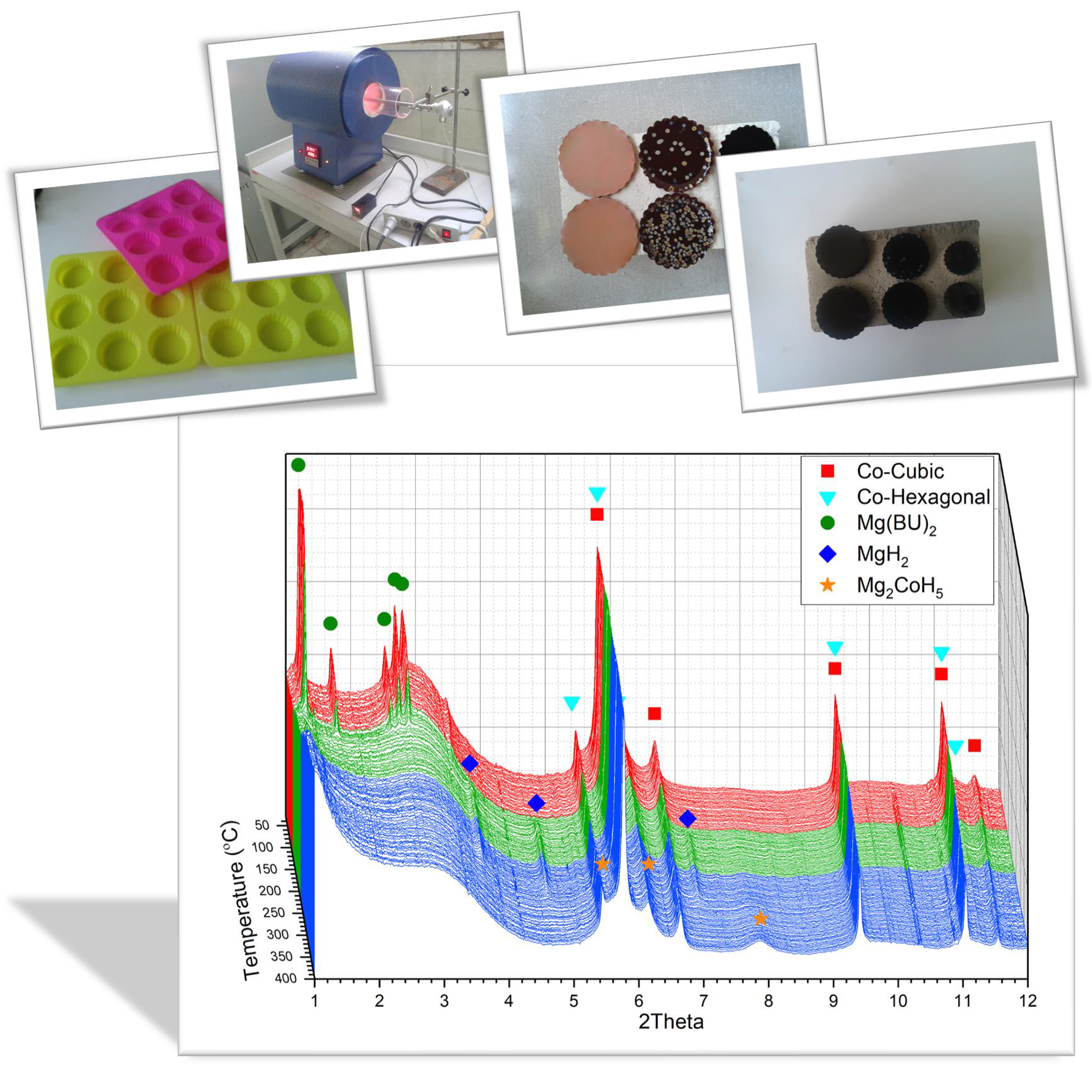
A selected amount of resorcinol (99%, Aldrich, St. Louis, MO, USA), formaldehyde in water (37 wt % stabilised by 10–15% methanol, Aldrich, St. Louis, MO, USA), and Na2CO3 (99.999%, Aldrich, St. Louis, MO, USA) as catalyst were dissolved in deionised water. For each run, the sol was prepared by considering the specified Reactant/Solution and pH values (Table 1). The solutions were transferred to a silicon mould (Figure 1a), sealed in a chamber to avoid any solvent evaporation during gelation (Figure 1b). The gelation process was done in three distinct steps: (i) one day at 23 °C (ii) one day at 50 °C, and (iii) three days at 90 °C. The formed disk-shaped gels removed from the mould were cooled down to room temperature and immersed in acetone for solvent replacement (Figure 1c). The acetone bath was renewed every day to minimize the residual water. After three days of solvent exchange, the specimens loaded in a tube furnace and heated (with 2 °C min−1 rate) to the suggested pyrolysis temperature under the flow of nitrogen, and maintained at that temperature for 6 h for a full pyrolysis process (Figure 1d). A 4-h activation process was carried out on the selected sample with the lowest shrinkage at 900 °C under a continuous flow of CO2. SEM/FESEM imaging techniques were employed to study the morphology of the product, and the surface area and pore volume of the synthesised xerogels were evaluated using BET technique, based on the Ar adsorption isotherm at liquid nitrogen temperature.
The activated xerogel was selected for the confinement process. Impregnation of cobalt was carried out by an overnight immersing 0.5 g carbon xerogel in a 1-M Co(NO3)2.6H2O solution in deionised water. The infiltrated gels were transferred to an autoclave to dry and nitrate decompose to form metal oxide, while heating the autoclave to 400 °C under vacuum. To reduce the formed oxide to pure metal, the autoclave was loaded with 100 bar of hydrogen, heated up to 500 °C and left at that temperature for 8 h. To add magnesium precursor to the cobalt-decorated carbon xerogel, the gel was immersed into 1.0-M Di-n-butylmagnesium (Mg(BU)2) in heptane (Aldrich, St. Louis, MO, USA) overnight. The same process was repeated by 3.0-M Mg(BU)2 that was produced using commercial 1.0-M Mg(BU)2, by evaporating the solvent (heptane) to reduce its volume to one third. All of the processes were handled inside a glovebox to avoid any contact with oxygen or water. To remove the non-confined reagent, which remained on the surface of the xerogel, scratching on abrasive paper (1000 girt) was used. The amount of compound uptake was evaluated using Spectro Arcos model ICP-OES (Thermo Fisher Scientific, Waltham, MA, USA).
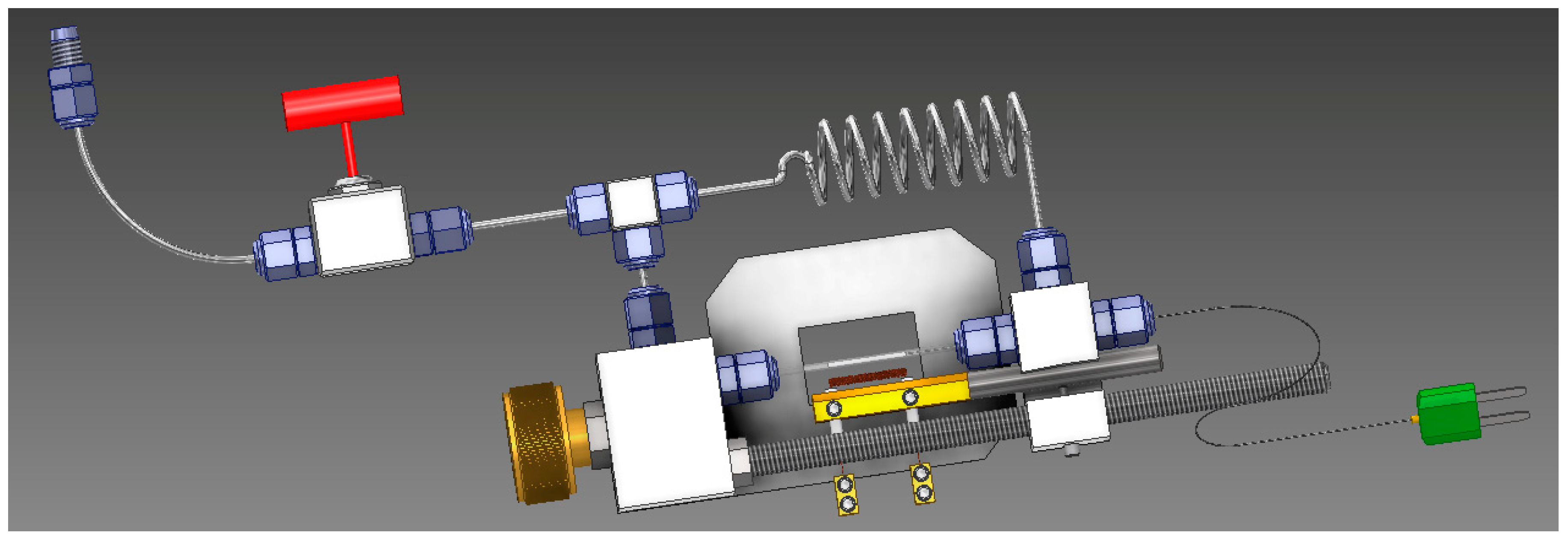
In situ synchrotron radiation powder X-ray diffraction (SRPXD) experiments were done at DESY, Hamburg (P02.1 beamline- PETRA III) [25]. The infiltrated sample was ground and loaded into a sapphire capillary. The tube was assembled to the main sample holder. To start the experiment, 100 bar of hydrogen applied to the sample and temperature raised to 400 °C with 10 °C min−1 heating rate. To track the phase transition as a function of temperature, the temperature corresponding to each diffraction pattern was also measured using an internal thermocouple, in contact with the powder. Figure 2 shows a schematic of the sample holder [26].
3. Results and Discussion
The suggested experiments in the framework of the BBD design (Table 1) were conducted, and the final percentage of the shrinkage was compared with the formed disk after gelation was considered as the response measure. According to RSM design, a 2nd-order algebraic equation can be fitted to our results. RSM gives the following full quadratic model, where Y is the response (total shrinkage after pyrolysis). β0, βi, βii and βij, are intercept constant, linear, quadratic and interaction parameters’ coefficients, respectively—see Equation (1). K denotes to the number of design parameters and ε represents the random-error residual associated with the experiments. This model returns an understanding of the impact of each variable and their mutual interactions on the objective response:
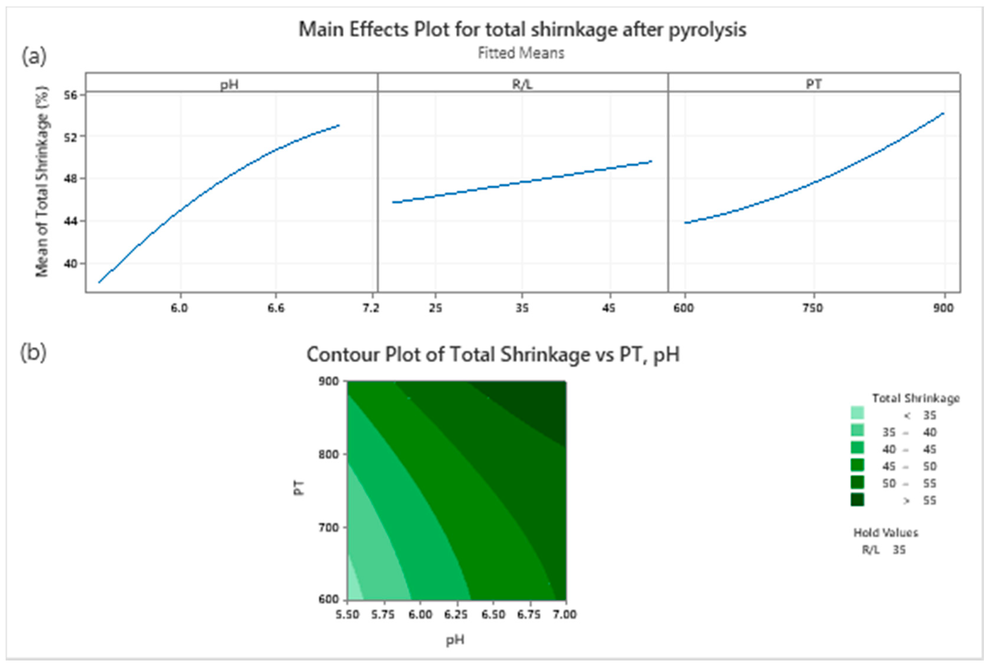
To determine the quality of the fitted model, an Analysis of Variance (ANOVA) was performed (Table 2). As a result, only two linear components of the fitted equation have a statistically significant effect on the final response parameter (Table 2)—concerning the calculated p-Values pH and PT had over 95% confidence thresholds. This means any change in pH and PT during the synthesis process will cause a different shrinkage, while if R/L changes in the range of 20% to 40%, the final volume will not vary significantly.
The main effect of each parameter is also presented in Figure 3a; a decrease in the pH or PT results in decreasing the degree of final shrinkage of the xerogel. In essence, studying Figure 3 and Table 2 further, i.e., the contour plot derived from the proposed fitted equation (Figure 3b), the final shrinkage of a carbon xerogel can be predicted based on the two significant synthesis parameters (pH and the pyrolysis temperature). With an R/L equal to 35%, the minimum shrinkage will be obtained in the corner of the studied PT and pH area. Therefore, by choosing PT in the range of 600–700 °C and pH between 5.5–5.7, a structure with very low degree of shrinkage can be obtained—see Figure 3b. The proposed global minimum of the final shrinkage was already tested as run number two, with 33.23% shrinkage at pH = 5.5, R/L = 35% and PT = 600 °C.
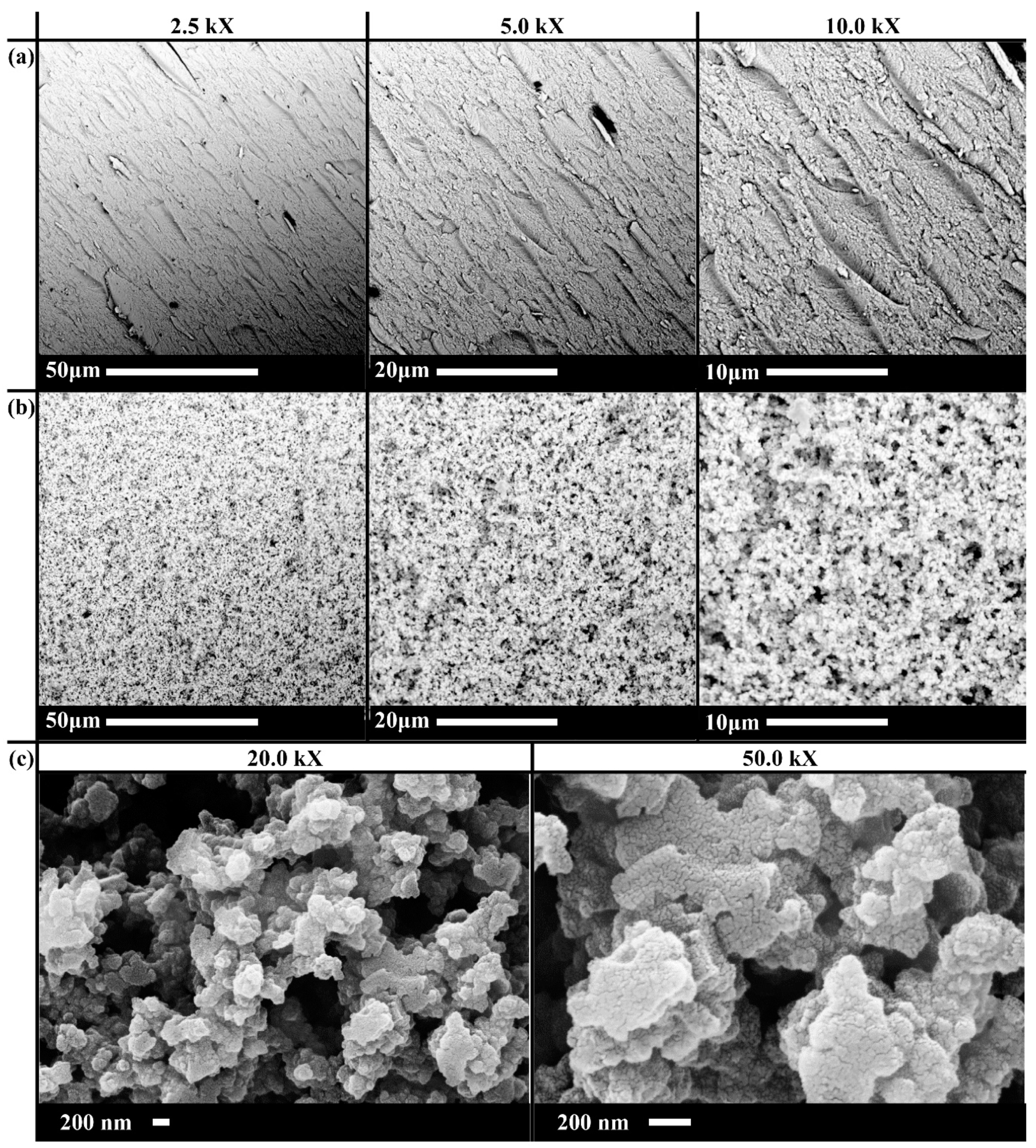
The morphological structure of the synthesised carbon xerogels was evaluated by different electron microscopy techniques. To glean a first impression on the effect of shrinkage on the microstructure of the specimen, the SEM images of the samples with highest (Figure 4a) and lowest (Figure 4b) shrinkage during the formation process (sample numbers 15 and 2, respectively) are presented. Severe shrinkage in sample number 15 leads to the formation of a dense structure with very low porosity, whilst for number two, a uniform pore distribution with a complex hierarchical porosity can be formed upon synthesis, with minimum shrinkage.
Activated carbon xerogel was also examined by field emission SEM. The high-resolution FESEM image presents a closer view of the carbon matrix which seems to be made of laminae of certain graphite-like layers in an ‘onion-like’ assembly. The 2D structure of graphite-like structures (Figure 4c) has a superior location to trap precursor molecules between its layers. Moreover, due to its high thermal conductivity, this location will serve as a preferential point for the nucleation of nanoparticles formed through a chemical reaction [27]. On the other hand, its geometry will (i) enhance the stability of the composite by securing the position of the confined nanoparticles, and (ii) prevent agglomeration of nanoparticle through multiple chemical reactions, which will enhance the cyclability behaviour of the composite [28]. Moreover, the high thermal conductivity of graphite-like structures will render this structure a good candidate for hydrogen storage applications, where its elevated heat-transfer properties will enhance the kinetics of hydrogen uptake/release in storage tanks [29].
The microstructure properties of the optimised carbon xerogels, before and after the activation process, is reported in Table 3. As a result of carbon xerogel activation, a sample with almost the same pore diameter, but a larger specific surface area, was obtained. This observation was in agreement with the result reported by Contreras et al. [30].
ICP analysis revealed the number of different substances uptaken. In the case of 1 M cobalt nitrate, 0.34 mmol/g gel was infiltrated, while the amount of magnesium in 1 and 3 M Di-n-butylmagnesium is 0.98 and 0.91 mmol/g gel. Although the concentration of the precursor solutions was the same, the amount of confined magnesium is around three times higher than the cobalt uptake. The difference is due to a different characteristics of the main solutions, while Magnesium is introduced by organic solution and cobalt is present in an aqueous solution. This can be due to the hydrophobic nature of RF carbon xerogel [31] which will cause lower wettability followed by a lower capillary pressure for uptake in the case of aqueous solutions.
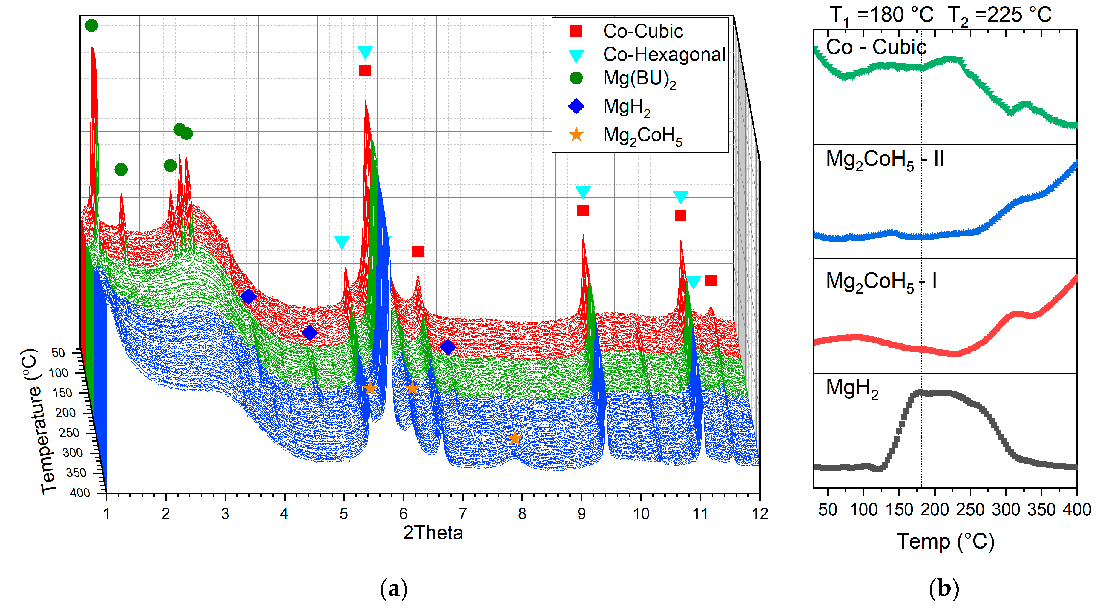
The phase evolution as a function of temperature is shown in Figure 5a. The starting structure, in addition to the peaks, belong to n-butylmagnesium; two polymorphs of cobalt are also present, one hexagonal [32] and one cubic [33] form of the Co. These two structures were formed during the indirect reduction of the infiltrated cobalt nitrate, as discussed earlier in the Materials and Methods section. The mechanism of this transition was studied in detail by Ghaani et al. [24]. Direct conversion of Mg(Bu)2 into MgH2 completed at about 180 °C (Figure 5a—red area) according to the following reaction, in Equation (2):
Mg(C4H9)2(s) + 2H2(g) → MgH2(s) + 2C4H10(g)
The formed MgH2 is stable up to 225 °C (Figure 5a—green area), and at higher temperatures the peaks of magnesium hydride disappear (Figure 5a—blue area), and Mg2CoH5 forms through the Co + MgH2 → Mg2CoH5 reaction [34,35]. Low levels of crystallinity, alongside high XRD background levels due to the nature of the amorphous carbon scaffold, coupled with the overall complexity of the system, rendered tracking all of the phase transitions in these nano-confined systems difficult. The particles form inside the aerogel nanopores, resulting in in broadened diffraction peaks (featuring, ipso facto, large FWHM). Since there are very many randomly oriented grains (crystallites) in the bulk of these nanoparticles, it is was exceedingly difficult to ascertain a certain direction of crystallisation or ordered crystallographic planes in any one specimen of these samples; in this sense, one may consider many of these samples as exhibiting lower levels of overall, aggregate crystallinity. To address these challenges and track the formed phases more accurately, the area below the peaks with minimum overlap with other phases was calculated, and this is shown in Figure 5b.
At 255 °C, occurring simultaneously with consumption of the MgH2 and cubic cobalt, two peaks of Mg2CoH5 with cubic structure [8] appear at 2θ = 5.49° and 7.83°. This observation proves unambiguously the in situ formation of the nano-confined Mg2CoH5 inside the carbon xerogel’s scaffold structure.
4. Conclusions
Given the overriding objective of obtaining and leveraging high-performance 3D porous carbon structures, whilst maintaining simplicity and low cost in its synthesis route, we have investigated—and realised successfully—the in situ formation of a complex hydride inside this optimised carbon xerogel porous scaffold-‘hosting’ material. In the first stage, the host was optimised through multi-parameter optimisation to minimise the carbon xerogel shrinkage during its formation. We studied the effect of pH, R/L and PT on the structure of the final carbon xerogel. It was found that the level of R/L does not have a significant effect on the final shrinkage of the formed structure of the xerogel. We showed that minimum shrinkage (33.23%) can be obtained through a synthesis process with R/L = 35% and PT = 600 °C at pH = 5.5.
During the second stage, during two discrete steps, cobalt nitrate and Di-n-butylmagnesium as the elemental cobalt and magnesium precursors required for the formation Mg2CoH5 were infiltrated into the optimised carbon xerogel. Perhaps unsurprisingly, it was found that the uptake of an organic-based compound is significantly higher than aqueous-based reagents due to the hydrophobic nature of the carbon xerogel and lower capillary pressure inside the scaffold pores in the case of aqueous systems.
During the third stage, MgH2 formed through the reaction of Mg(BU)2 with hydrogen at about 150 °C; at 225 °C, it will react with previously infiltrated cobalt nanoparticles to form Mg2CoH5. The mechanism of the formation of ternary Mg2CoH5 was investigated by studying the phase transition as a function time. The formed composite can be used in hydrogen storage applications as a compound exhibiting high gravimetric and volumetric hydrogen capacity and very promising ‘cyclability’ properties. For future work, a larger quantity of the sample needs to be prepared for a more accurate investigation on hydrogenation/dehydrogenation kinetics, and also a careful characterization of the cyclability and longer-term resilience of the formed composite. These results will be very helpful in showcasing the characteristics and advantages, and any possible drawbacks, of this most promising composite material, to afford a comprehensive comparative analysis vis-à-vis other more well-developed hydrogen storage materials.
It may be the case that molecular simulation [36]—especially in its guise of Density Functional Theory (DFT)—can deal with complicated chemical reactions in disparate electronic milieu of different atomistic environments of hydrides in heterogeneous scaffold environments; indeed, this may be able to optimise further materials design and selection. However, the appropriate selection and careful benchmarking and tailoring of DFT functionals in interfacial systems [37] will be very important in this vein, to ensure the highest quality of interatomic interactions, as well as in molecular simulation handling the wider challenge of handling possible hydrogen bonding accurately [38], which may well be important in some promising classes of hydrogen storage materials.
Author Contributions
M.R.G., M.A., M.C. and N.J.E. conceived the study conceptually. M.R.G. and M.A. designed and built the synthesis setup. M.R.G. and M.A. carried out the aerogel formation experiments, as well as characterisations. M.C. contributed importantly with an interpretation of results and crystallographic mechanisms. N.J.E. contributed importantly to the experimental design and statistical analysis. All authors have read and agreed to the published version of the manuscript.
Funding
This research received no external funding.
Acknowledgments
M.R.G. wishes to express his thanks to Torben R. Jensen for his hosting and support. We acknowledge DESY (Hamburg, Germany), a member of the Helmholtz Association HGF, for the provision of experimental facilities. Parts of this research were carried out at PETRA III and we would like to thank Ann-Christin Dippel for assistance in using photon beamline.
Conflicts of Interest
The authors declare no conflict of interest.
References
- Schlapbach, L.; Züttel, A. Hydrogen-storage materials for mobile applications. Nature 2001, 414, 353–358. [Google Scholar] [CrossRef] [PubMed]
- Felderhoff, M.; Weidenthaler, C.; Von Helmolt, R.; Eberle, U. Hydrogen storage: The remaining scientific and technological challenges. Phys. Chem. Chem. Phys. 2007, 9, 2643. [Google Scholar] [CrossRef] [PubMed]
- Belosludov, R.; Bozhko, Y.; Zhdanov, R.; Subbotin, O.S.; Kawazoe, Y.; Belosludov, V.R. Hydrogen hydrates: Equation of state and self-preservation effect. Fluid Phase Equilibria 2016, 413, 220–228. [Google Scholar] [CrossRef]
- Catti, M.; Ghaani, M.R.; Pinus, I. Overpressure Role in Isothermal Kinetics of H2 Desorption–Absorption: The 2LiBH4–Mg2FeH6 System. J. Phys. Chem. C 2013, 117, 26460–26465. [Google Scholar] [CrossRef]
- Ghaani, M.R.; Catti, M.; Nale, A. Thermodynamics of Dehydrogenation of the 2LiBH4–Mg2FeH6 Composite. J. Phys. Chem. C 2012, 116, 26694–26699. [Google Scholar] [CrossRef] [Green Version]
- Reiser, A. The application of Mg-based metal-hydrides as heat energy storage systems. Int. J. Hydrogen Energy 2000, 25, 425–430. [Google Scholar] [CrossRef]
- Cerny, R.; Bonhomme, F.; Yvon, K.; Fischer, P.; Zolliker, P.; Cox, D.; Hewat, A. Hexamagnesium dicobalt undecadeuteride Mg6Co2D11: Containing [CoD4]5− and [CoD5]4− complex anions conforming to the 18-electron rule. J. Alloys Compd. 1992, 187, 233–241. [Google Scholar] [CrossRef]
- Zolliker, P.; Yvon, K.; Fischer, P.; Schefer, J. Dimagnesium cobalt(I) pentahydride, Mg2CoH5, containing square-pyramidal pentahydrocobaltate(4-) () anions. Inorg. Chem. 1985, 24, 4177–4180. [Google Scholar] [CrossRef]
- Fernández, I.G.; Meyer, G.; Gennari, F. Reversible hydrogen storage in Mg2CoH5 prepared by a combined milling-sintering procedure. J. Alloys Compd. 2007, 446, 106–109. [Google Scholar] [CrossRef]
- Fernández, I.G.; Gennari, F.; Meyer, G. Influence of sintering parameters on formation of Mg–Co hydrides based on their thermodynamic characterization. J. Alloys Compd. 2008, 462, 119–124. [Google Scholar] [CrossRef]
- Fernández, I.G.; Meyer, G.; Gennari, F. Hydriding/dehydriding behavior of Mg2CoH5 produced by reactive mechanical milling. J. Alloys Compd. 2008, 464, 111–117. [Google Scholar] [CrossRef]
- Gennari, F.; Castro, F. Formation, composition and stability of Mg–Co compounds. J. Alloys Compd. 2005, 396, 182–192. [Google Scholar] [CrossRef]
- Chen, J.; Takeshita, H.T.; Chartouni, D.; Kuriyama, N.; Sakai, T. Synthesis and characterization of nanocrystalline Mg2CoH5 obtained by mechanical alloying. J. Mater. Sci. 2001, 36, 5829–5834. [Google Scholar] [CrossRef]
- Berube, V.; Radtke, G.; Dresselhaus, M.; Chen, G. Size effects on the hydrogen storage properties of nanostructured metal hydrides: A review. Int. J. Energy Res. 2007, 31, 637–663. [Google Scholar] [CrossRef]
- Berlouis, L.; Cabrera, E.; Hall-Barientos, E.; Hall, P.J.; Dodd, S.B.; Morris, S.; Imam, M.A. Thermal analysis investigation of hydriding properties of nanocrystalline Mg–Ni- and Mg–Fe-based alloys prepared by high-energy ball milling. J. Mater. Res. 2001, 16, 45–57. [Google Scholar] [CrossRef]
- Mezzavilla, S.; Zanella, C.; Aravind, P.R.; Della Volpe, C.; Soraru, G.D. Carbon xerogels as electrodes for supercapacitors. The influence of the catalyst concentration on the microstructure and on the electrochemical properties. J. Mater. Sci. 2012, 47, 7175–7180. [Google Scholar] [CrossRef]
- Chen, S.-M.; Ramachandran, R.; Mani, V.; Saraswathi, R. Recent advancements in electrode materials for the high-performance electrochemical supercapacitors: A review. Int. J. Electrochem. Sci. 2014, 9, 4072–4085. [Google Scholar]
- Zaid, K.; Suriani, A.B. A review on electrode materials used in capacitive deionization processes for water treatment applications. Sci. Int. 2017, 29, e289. [Google Scholar]
- ElKhatat, A.M.; Al-Muhtaseb, S.A. Advances in Tailoring Resorcinol-Formaldehyde Organic and Carbon Gels. Adv. Mater. 2011, 23, 2887–2903. [Google Scholar] [CrossRef]
- Yan, M.-F.; Zhang, L.-H.; He, R.; Liu, Z.-F. Synthesis and characterization of carbon aerogels with different catalysts. J. Porous Mater. 2015, 22, 699–703. [Google Scholar] [CrossRef]
- Liang, C.; Sha, G.; Guo, S. Resorcinol–formaldehyde aerogels prepared by supercritical acetone drying. J. Non-Crystal. Solids 2000, 271, 167–170. [Google Scholar] [CrossRef]
- Yamamoto, T.; Nishimura, T.; Suzuki, T.; Tamon, H. Control of mesoporosity of carbon gels prepared by sol–gel polycondensation and freeze drying. J. Non-Crystal. Solids 2001, 288, 46–55. [Google Scholar] [CrossRef]
- Durairaj, R.B. Resorcinol: Chemistry, Technology and Applications; Springer: Berlin/Heidelberg, Germany, 2005. [Google Scholar]
- Ghaani, M.R.; Catti, M. Investigation on the kinetic mechanism of the reduction of Fe2O3/CoO-decorated carbon xerogels: A non-isothermal study. J. Solid State Chem. 2019, 277, 368–375. [Google Scholar] [CrossRef]
- Herklotz, M.; Scheiba, F.; Hinterstein, M.; Nikolowski, K.; Knapp, M.; Dippel, A.-C.; Giebeler, L.; Eckert, J.; Ehrenberg, H. Advances inin situpowder diffraction of battery materials: A case study of the new beamline P02.1 at DESY, Hamburg. J. Appl. Crystallogr. 2013, 46, 1117–1127. [Google Scholar] [CrossRef]
- Jensen, T.R.; Nielsen, T.K.; Filinchuk, Y.; Jørgensen, J.-E.; Cerenius, Y.; Gray, E.M.; Webb, C.J. Versatile in situ powder X-ray diffraction cells for solid–gas investigations. J. Appl. Crystallogr. 2010, 43, 1456–1463. [Google Scholar] [CrossRef] [PubMed] [Green Version]
- Nielsen, T.K.; Besenbacher, F.; Jensen, T.R. Nanoconfined hydrides for energy storage. Nanoscale 2011, 3, 2086. [Google Scholar] [CrossRef]
- Gutowska, A.; Li, L.; Shin, Y.; Wang, C.M.; Li, X.S.; Linehan, J.C.; Smith, R.S.; Kay, B.D.; Schmid, B.; Shaw, W.J.; et al. Nanoscaffold Mediates Hydrogen Release and the Reactivity of Ammonia Borane. Angew. Chem. Int. Ed. 2005, 44, 3578–3582. [Google Scholar] [CrossRef]
- Peng, D.; Ding, Z.; Zhang, L.; Fu, Y.; Wang, J.; Li, Y.; Han, S. Remarkable hydrogen storage properties and mechanisms of the shell–core MgH2@carbon aerogel microspheres. Int. J. Hydrogen Energy 2018, 43, 3731–3740. [Google Scholar] [CrossRef]
- Contreras, M.S.; Paez, C.; Zubizarreta, L.; Léonard, A.; Blacher, S.; Olivera-Fuentes, C.G.; Arenillas, A.; Pirard, J.-P.; Job, N. A comparison of physical activation of carbon xerogels with carbon dioxide with chemical activation using hydroxides. Carbon 2010, 48, 3157–3168. [Google Scholar] [CrossRef]
- Fricke, J.; Tillotson, T. Aerogels: Production, characterization, and applications. Thin Solid Films 1997, 297, 212–223. [Google Scholar] [CrossRef]
- Morozkin, A.V. Gd–Co–Ge system at 870/1070 K. Intermetallics 2012, 25, 136–138. [Google Scholar] [CrossRef]
- Singh, M.; Barkei, M.; Inden, G.; Bhan, S. High-temperature X-ray diffraction study on Co75Sn25 alloy. Phys. Status Solidi 1985, 87, 165–168. [Google Scholar] [CrossRef]
- Huot, J.; Hayakawa, H.; Akiba, E. Preparation of the hydrides Mg2FeH6 and Mg2CoH5 by mechanical alloying followed by sintering. J. Alloys Compd. 1997, 248, 164–167. [Google Scholar] [CrossRef]
- Norek, M.; Nielsen, T.; Polanski, M.; Kunce, I.; Płociński, T.; Jaroszewicz, L.R.; Cerenius, Y.; Jensen, T.R.; Bystrzycki, J. Synthesis and decomposition mechanisms of ternary Mg2CoH5 studied using in situ synchrotron X-ray diffraction. Int. J. Hydrogen Energy 2011, 36, 10760–10770. [Google Scholar] [CrossRef]
- Ghaani, M.R.; English, N.J. Hydrogen-/propane-hydrate decomposition: Thermodynamic and kinetic analysis. Mol. Phys. 2019, 117, 2434–2442. [Google Scholar] [CrossRef]
- Dev, P.; Agrawal, S.; English, N.J. Functional Assessment for Predicting Charge-Transfer Excitations of Dyes in Complexed State: A Study of Triphenylamine–Donor Dyes on Titania for Dye-Sensitized Solar Cells. J. Phys. Chem. A 2013, 117, 2114–2124. [Google Scholar] [CrossRef] [Green Version]
- Solomentsev, G.Y.; English, N.J.; Mooney, D.A. Hydrogen bond perturbation in hen egg white lysozyme by external electromagnetic fields: A nonequilibrium molecular dynamics study. J. Chem. Phys. 2010, 133, 235102. [Google Scholar] [CrossRef]
Figure 1.
The experimental setup used for xerogel preparation: (a) silicon mould to keep all the disks in the same shape, (b) sealed chamber to avoid any solvent loss during the gelation process, (c) solvent exchange process, (d) different levels of shrinkage for carbon xerogels after pyrolysis.
Figure 1.
The experimental setup used for xerogel preparation: (a) silicon mould to keep all the disks in the same shape, (b) sealed chamber to avoid any solvent loss during the gelation process, (c) solvent exchange process, (d) different levels of shrinkage for carbon xerogels after pyrolysis.

Figure 2.
High-pressure sample holder used for in situ synchrotron data collection.

Figure 3.
RSM main effect (a) and contour plots (b) for the total shrinkage of the carbon xerogel.

Figure 4.
(a) SEM images of the product with maximum shrinkage (sample number 15) (b) SEM images of the product with minimum shrinkage (sample number 2). (c) FESEM images of the activated carbon xerogel at different zoom levels.
Figure 4.
(a) SEM images of the product with maximum shrinkage (sample number 15) (b) SEM images of the product with minimum shrinkage (sample number 2). (c) FESEM images of the activated carbon xerogel at different zoom levels.

Figure 5.
(a) In situ synchrotron XRD patterns of a carbon xerogel infiltrated with Co + Mg(Bu)2 during the temperature-programmed reaction at 100 bar H2; Measurements were performed at DESY, Hamburg (λ = 0.2072 Å). (b) Standardised scale factors of MgH2 (2θ = 7.01°), Mg2CoH5 (2θ = 5.49° & 7.83°) and Co-cubic (2θ = 11.59°) as a function of temperature. Data were obtained from sequential Lorentzian peak fit of the in situ diffraction pattern.


Table 1.
Set of designed experiments according to BBD design.
| Run No. | Reactants/Solution (%) | pH | Pyrolysis Temperature (°C) |
|---|---|---|---|
| 1 | 35 | 5.5 | 900 |
| 2 | 35 | 5.5 | 600 |
| 3 | 50 | 5.5 | 750 |
| 4 | 30 | 5.5 | 750 |
| 5 | 35 | 6.25 | 750 |
| 6 | 30 | 6.25 | 900 |
| 7 | 35 | 6.25 | 750 |
| 8 | 50 | 6.25 | 900 |
| 9 | 30 | 6.25 | 600 |
| 10 | 50 | 6.25 | 600 |
| 11 | 35 | 6.25 | 750 |
| 12 | 35 | 7 | 600 |
| 13 | 20 | 7 | 750 |
| 14 | 50 | 7 | 750 |
| 15 | 35 | 7 | 900 |
Table 2.
ANOVA table of RSM represented a model for the final shrinkage.
| Source | DF | Adj SS | Adj MS | F-Value | p-Value |
|---|---|---|---|---|---|
| Model | 8 | 465.142 | 58.143 | 13.15 | 0.043 |
| Linear | 3 | 343.015 | 114.338 | 25.86 | 0.037 |
| pH | 1 | 222.606 | 222.606 | 50.35 | 0.019 |
| R/L | 1 | 9.738 | 9.738 | 2.20 | 0.276 |
| PT | 1 | 110.670 | 110.670 | 25.03 | 0.038 |
| Square | 2 | 12.818 | 6.409 | 1.45 | 0.408 |
| pH×pH | 1 | 10.842 | 10.842 | 2.45 | 0.258 |
| PT×PT | 1 | 4.940 | 4.940 | 1.12 | 0.401 |
| Two-Way Interaction | 3 | 12.377 | 4.126 | 0.93 | 0.555 |
| pH×R/L | 1 | 7.207 | 7.207 | 1.63 | 0.330 |
| pH×PT | 1 | 5.108 | 5.108 | 1.16 | 0.395 |
| R/L×PT | 1 | 0.062 | 0.062 | 0.01 | 0.917 |
| Error | 2 | 8.843 | 4.421 | ||
| Total | 10 | 473.984 |
Table 3.
BET values of the optimised carbon xerogels before and after activation.
| Sample Name | SBET(m2/g) | Vmicro(cc/g) | Vmeso(cc/g) | Dmax(nm) | Vtot(cc/g) |
|---|---|---|---|---|---|
| Sample no. 2 | 854 | 0.226 | 1.51 | 21 | 1.73 |
| Sample no. 2-ACT | 1756 | 0.582 | 2.75 | 20 | 3.23 |
© 2020 by the authors. Licensee MDPI, Basel, Switzerland. This article is an open access article distributed under the terms and conditions of the Creative Commons Attribution (CC BY) license (http://creativecommons.org/licenses/by/4.0/).
Share and Cite
MDPI and ACS Style
Ghaani, M.R.; Alam, M.; Catti, M.; English, N.J. In Situ Formation of Metal Hydrides Inside Carbon Aerogel Frameworks for Hydrogen Storage Applications. C 2020, 6, 38. https://0-doi-org.brum.beds.ac.uk/10.3390/c6020038
AMA Style
Ghaani MR, Alam M, Catti M, English NJ. In Situ Formation of Metal Hydrides Inside Carbon Aerogel Frameworks for Hydrogen Storage Applications. C. 2020; 6(2):38. https://0-doi-org.brum.beds.ac.uk/10.3390/c6020038
Chicago/Turabian StyleGhaani, Mohammad Reza, Mahdi Alam, Michele Catti, and Niall J. English. 2020. "In Situ Formation of Metal Hydrides Inside Carbon Aerogel Frameworks for Hydrogen Storage Applications" C 6, no. 2: 38. https://0-doi-org.brum.beds.ac.uk/10.3390/c6020038
Note that from the first issue of 2016, this journal uses article numbers instead of page numbers. See further details here.