1. Introduction
The unique characteristics of nanodiamonds (NDs), for example, their excellent optical and mechanical properties [
1] and the fluorescence properties of their nitrogen-vacancy (NV) centers, dependent on external physical fields [
2], opened the possibility of producing devices with nanoscale quantum sensing capabilities. NV-fluorescent NDs in fact are almost unique nanoprobes, allowing for the detection of changes in environmental parameters such as temperature [
3,
4] and magnetic [
5] and electric fields [
6]. In addition, the biocompatibility of NDs allows
in-vivo imaging [
7].
Recently, we demonstrated the synthesis of NV fluorescent NDs through pulsed laser ablation (PLA) of graphite in a nitrogen-containing environment. We carried out the synthesis in both a controlled nitrogen [
8] atmosphere and in liquid nitrogen [
9]. We also demonstrated the possibility to produce NDs within different confining media and starting targets [
10].
The most effective condition, in terms of number of fluorescent NDs and fluorescence intensity, is PLA in liquid nitrogen (LN
2), as reported in [
9]. The experimental drawback of this new technique is related to the yield in terms of material produced during the synthesis process. In fact, for biological application such as imaging or sensing, a relevant (~mg mass, not obtained in our previous work) amount of highly fluorescent pure ND material is required in order to obtain a good contrast with low laser pumping powers. In addition, a significant amount of NDs permits the employment of strong, industry-compatible, chemical cleaning techniques that allow for the removal of almost all the optically parasitic graphitic byproducts. The aim of this paper is to present our upgraded automatized experimental setup where laser ablation of graphitic targets in LN
2 produces significant quantities of nanopowders (pure NDs with NV centers + graphite) allowing for cleaning out the embedded NV-containing NDs, and to precisely estimate the liquid-nitrogen laser-ablated fluorescent nanodiamond production yield.
2. Materials and Methods
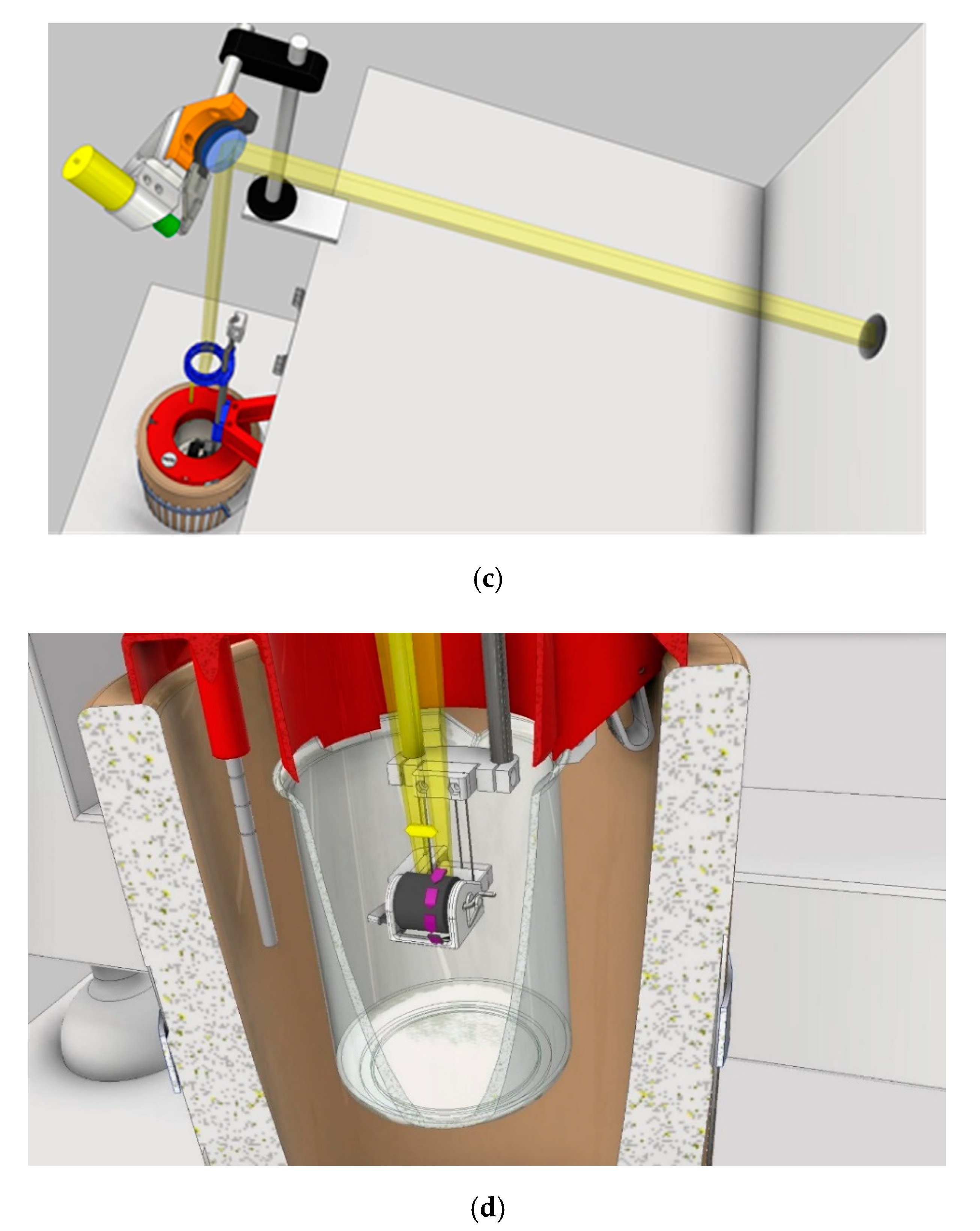
The experimental apparatus (general view, details, and schematics) is shown in
Figure 1. Pulsed laser irradiation is performed by using a KrF excimer laser (Lambda-Physik Coherent LPX220i) having wavelength of 248 nm and pulse duration of 20 ns. Laser energy is set to 690 mJ per pulse, and the laser is operated at a pulse rate of 10 Hz. The laser beam is deflected by a motor-driven oscillating mirror and consequently focused by a 400 mm-focal-length lens on the target surface. The pyrolytic graphite target is placed in a glass vial (“internal LN
2 vial” in
Figure 1a, where the top surface of the target is covered by a ~5 mm-thick liquid nitrogen layer. To limit the unavoidable liquid nitrogen evaporation that occurs during the high-power excimer laser irradiation, the glass box was placed in a polystyrene box (“external LN
2 dewar” in
Figure 1a) and filled with liquid nitrogen. The ablation process was automatized as much as possible with the aim to perform ~hours of deposition. The system was then equipped with three additional step-motor driven movements (
Figure 1b): the Z-movement, the target rotation around its central cylindrical axis, and the laser beam rastering along the graphite cylinder height. These movements are controlled with Arduino© and more thoroughly described in
Figure 1. The movement along the Z-axis allows movement of the target up and down along the vertical direction during the deposition process. It is also employed before the ablation procedure starts, to put the graphite target inside the internal LN
2 vial, in a position in which the top surface is covered by a ~5 mm thick LN
2 layer. We have found empirically that this LN
2 layer thickness is a good compromise between the confining requisites needed for NDs to nucleate from the graphite and the minimization of UV laser fluence losses due to liquid absorption/scattering. During the ablation process and the consequent LN
2 evaporation, this motor-driven, Arduino-controlled movement allows the target to downshift, with a specifically calibrated constant speed, in order to maintain the same LN
2 layer thickness above the target surface.
The other two movements allow the homogeneous ablation of the whole graphite cylindrical surface and also help to avoid the formation of detrimental macroscopic craters in the target. The first movement is the target rotation; the cylindrical graphite target rotates with a specific angular velocity. The second movement is the laser beam rastering along the longitudinal cylinder height. This movement is obtained by putting the mirror in a holder that can oscillate. The maximum oscillation angle of the mirror is set by observing where the laser beam is impinging on the target surface, and avoiding that the laser beam goes beyond the target length. These three movements are a crucial upgrade in the experimental apparatus, increasing the laser-deposition from ~µg to ~mg of material. In fact, the movements also minimize the manual operations required during the ablation, thus allowing a more efficient use of the deposition time, and avoiding continuous manual refills of the LN2 level above the graphite target. This upgrade allowed us to perform more than 6 h of deposition (but longer depositions can be done and repetition rate of the laser can be safely increased up to 100 Hz), with partial liquid nitrogen refills at 45 minute interdelays, thus reaching ~57 mg of synthesized material (pure NDs with NV centers + graphite) as opposed to previous fractions of µg. In fact now, with all the procedures adopted and the consequent technical development of the apparatus, we can make around 200.000 laser shots per deposition session, as opposed to the 20.000 laser shots previously.
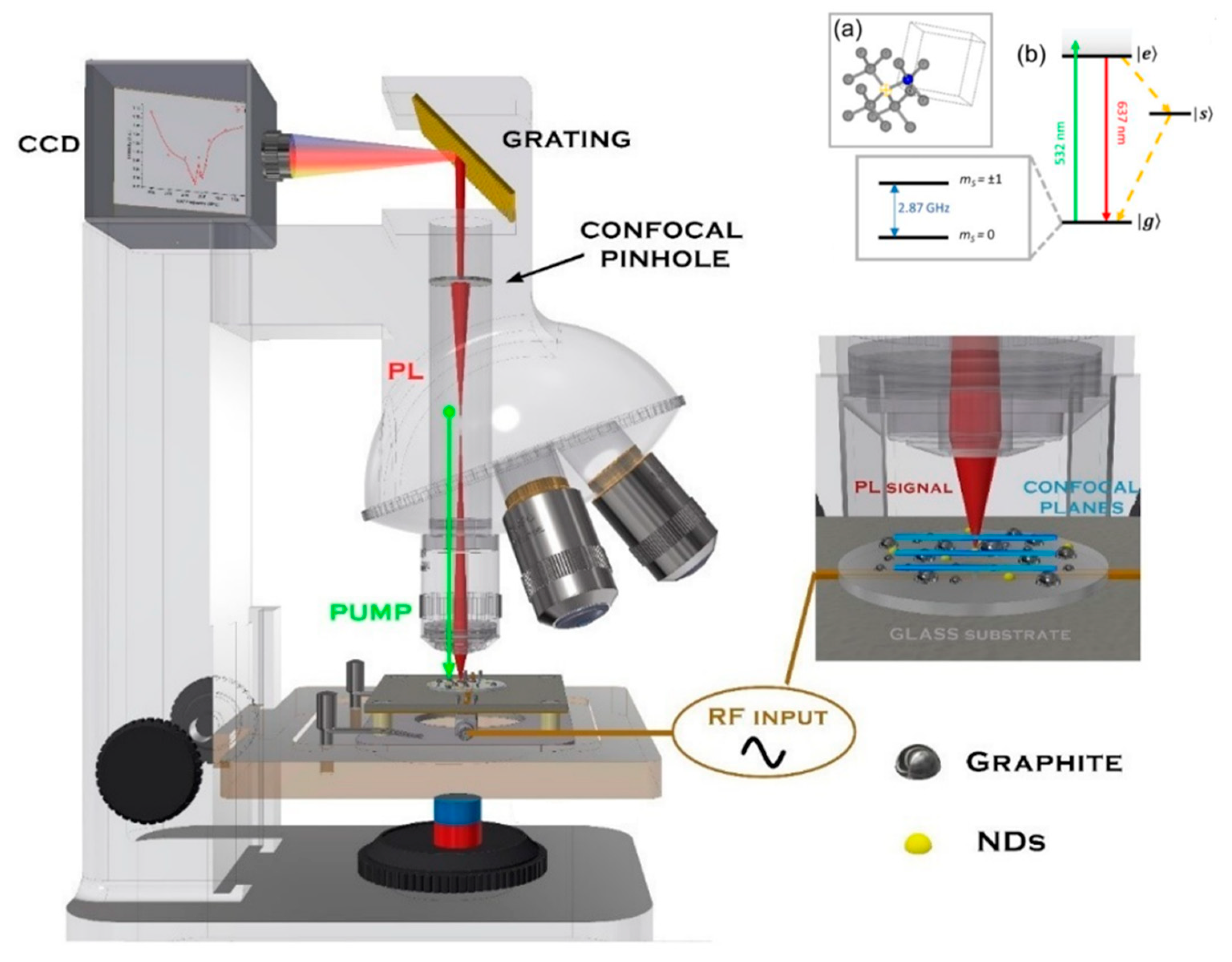
The photoluminescence spectra and the optically detected magnetic resonance spectra (ODMR) of our samples were measured employing a confocal microRaman Jobin–Yvon LabRam apparatus, where the confocal microscope section is represented schematically in
Figure 2. The excitation and the collection of the light from the micrometrically sized region of our samples were accomplished with a 100× objective. The sample was fixed on an epoxy-glass sample holder equipped with a Hertzian RF antenna (when measuring ODMR), which provided the RF pumping of the NV ground state energy levels, |g>, to excited state, |e> (see the energetic levels scheme in
Figure 2). Under tunable radiofrequency irradiation, we probed the microphotoluminescence spectrum coming from a ~2 µm × 2 µm × 5 µm volume containing an ensemble of NDs and performed an optical imaging of the emitting NDs. In particular, we equipped such a micro-Raman/microphotoluminescence apparatus with a tunable radiofrequency (RF) source, capable of furnishing up to 1 W of RF power in the 2.6–3.2 GHz range. The RF irradiation served as the ground |g> level pump to suitably populate the
mS = ± 1 sublevels, which are essential to activate the RF-dependent fluorescence mechanism related to the NV
− defect center in (nano)diamonds [
2]. We then recorded the microphotoluminescence spectra on a ~2 µm × 2 µm × 5 µm region (using an Olympus 50×, NA = 0.5, and working distance = 10.7 mm objective) where a cluster assembly of NDs was present at the optical imaging, while varying the RF frequency in the 2.6–3.2 GHz spectral region at constant 0.5 W power.
The bare photoluminescence spectra were recorded when no RF irradiation was superimposed on the NDs samples.
3. Results and Discussion
After the deposition, we followed two graphite cleaning procedures: the first relying on long-lasting thermal annealing of the nanopowders in order to remove as much graphite as possible, and the second employing a sulfonitric solution with a selective removal of graphite that achieves the preservation of the embedded NDs.
The thermal annealing at 425 °C and atmospheric condition was performed [
11] to remove selectively the
sp2 carbon atoms (the
sp3 carbon atoms require a temperature higher than 500 °C to be oxidized). Assuming an efficiency of the graphite–diamond transition of 1% (but Yang et al. [
12] reported efficiency for ablation of graphite in water up to 5%), the amount of pure NDs was estimated to be on the order of ~mg. The morphological analysis of the sample was done via scanning electron microscopy (SEM). Fluorescence and optically detected magnetic resonance of the samples were also analyzed. Typical SEM images for the as-deposited (as dep) sample and for those that were annealed (5 h ann and 77 h ann) are reported in
Figure 3. As it can be seen, nanostructures having a size in the order of hundreds nm were formed. From comparison of the SEM images (“as dep” vs. “ann” samples), one can easily see that the NDs are completely embedded within the parasitic graphite matrix. When the
sp2 carbon atoms are etched under thermal oxidation (425 °C), the morphology of the sample significantly changes.
Figure 3 (5 h ann) shows how the nanoparticles become more detached from the surrounding graphitic environment. The visible surface of the NDs is partially etched and it is not as smooth as in the “as dep” sample, indicating that the oxygen atoms act as efficient catalyzers for the removal of the NDs graphitic surface layers. Worth noting is the presence of submicrometric “holes” in the graphitic matrix (
Figure 3, 5 h ann)—those are likely due to a complete removal of the
sp2 carbon atoms “gluing” the NDs clusters to the surrounding graphite. After 77 h of additional annealing (
Figure 3, 77 h ann), this very situation is even more clear. The separation between the NDs borders and the graphite matrix is clearly observed—the amorphous carbon atoms and the NDs no longer form a continuous film as in the “as dep” sample. The etching process is digging (i.e., removing atoms) around and below the nanoparticles. This proves further that the nanoparticle core is not made by
sp2 atoms, but by
sp3 hybridized carbon atoms.
As seen from SEM, this method is efficient only in partially removing the NDs-surrounding graphite. For this reason, we also followed the alternative cleaning protocol that consists of treating ablation soot in acid. The methodology, adapted from a detonation NDs industrial treatment [
13], starts with dispersion of the soot in 30 mL of sulfonitric solution (three parts sulfuric acid at 98% concentration, one part nitric acid at 65% concentration). The mixture is then heated to 190 °C and kept under reflux for 3 h using an oil bath and a recondensation column. The resulting solution is then cooled and neutralized with NaOH. In order to deposit the NDs, the neutralized solution is then centrifuged for 30 min at 3000 rpm. Subsequently, the supernatant liquid is decanted and the sediment washed with distilled water in order to remove the salts formed during the neutralization, and centrifuged again. After drying, the samples were characterized via SEM imaging as reported in
Figure 4.
The yield of the chemical purification process, quantified as mass of the final product over the mass of the total ablation soot, is 7 ± 1%. This result is in line with other research based on laser ablation techniques that report yields between 5 and 10% [
13,
14]. HPHT shows yields around 15% [
15] and cavitation-assisted techniques around 10% [
16]. Detonation falls in the 4–10% range of the mass of the initial explosive charge mass [
16,
17].
NV-center optical properties were characterized by studying the NDs fluorescence spectra of our nanopowders under continuous 532 nm laser irradiation (
Figure 5) using the confocal apparatus described in the previous section. A broad red emission was detected, consistent with the well-established [
18] NV
− radiation pattern. An additional photoluminescence tail, probably due to graphitic surface layers on the NDs, was observed in the red region of the spectrum (>700 nm). The most important message is that the photoluminescence after the thermal and chemical treatments, performed as described, was still compatible with that observed in our previous work [
8,
9]. The sharp peaks at <600 nm are the D and G Raman peaks related to residual NDs-surrounding graphite shells. ODMR measurements are sensitive only to NV
− center fluorescence [
2]. The observable effect is that the NV
− fluorescence undergoes a significant intensity change when radiofrequency coirradiation is superimposed to the samples and tuned to around 2870 MHz (transition of NV ground state energy level |g> to excited state |e>, as illustrated in
Figure 2)
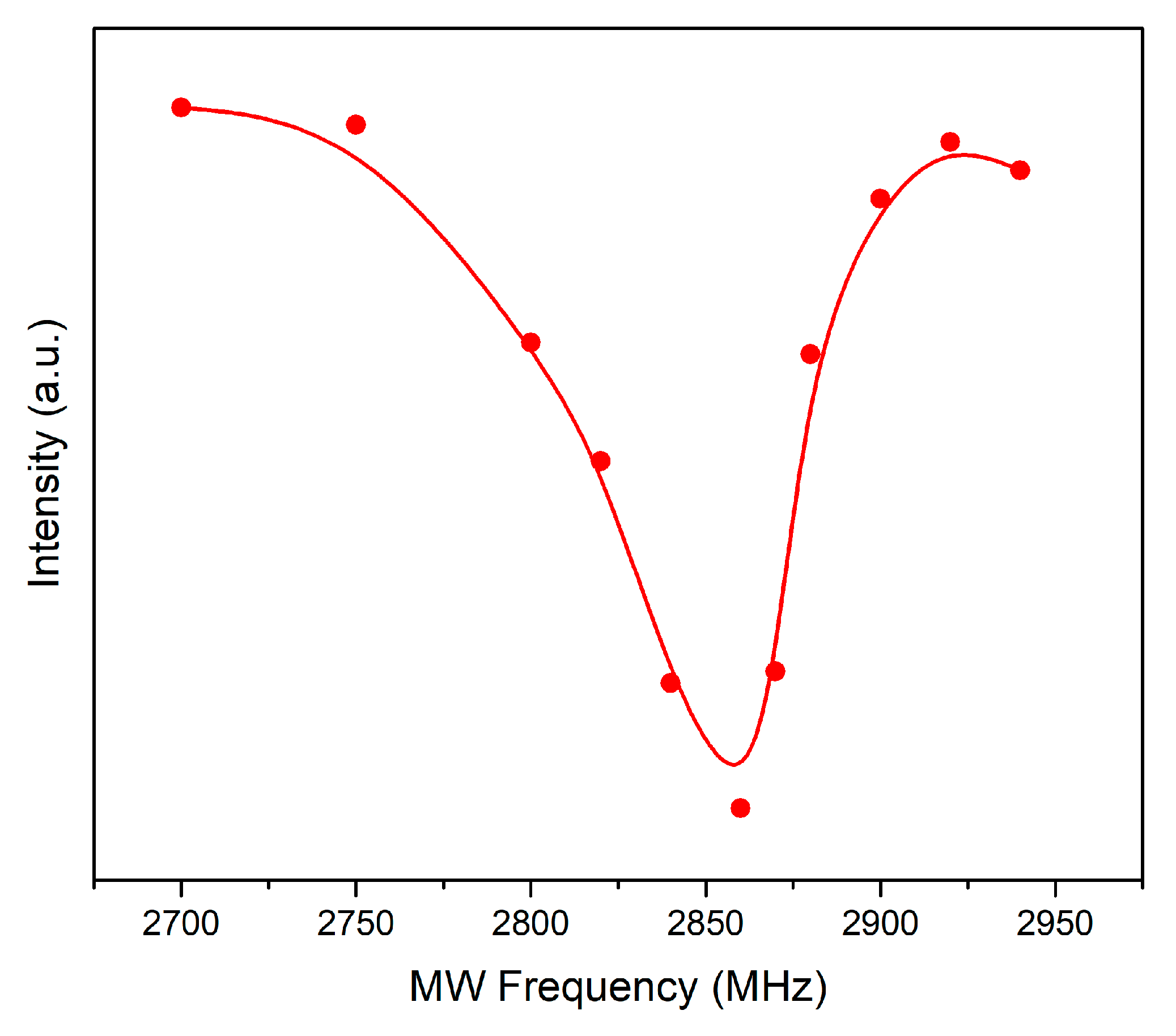
In fact, the ODMR curve (
Figure 6) confirms the presence of NV
− centers as testified by the ~2870 MHz fluorescence dip. In particular, its spectral broadness is compatible with previous observation [
8] and it is attributed to local strain fields acting on the observed micrometric-sized NDs clusters.


 ,
, 