
Reduction of Device Operating Temperatures with Graphene-Filled Thermal Interface Materials


Phonon Optimized Engineered Materials (POEM) Center, Bourns College of Engineering, University of California-Riverside, Riverside, CA 92521, USA
†
Present address: Intel Corporation, Hillsboro, OR 97124, USA.
C 2021, 7(3), 53; https://0-doi-org.brum.beds.ac.uk/10.3390/c7030053
Submission received: 16 June 2021
/
Revised: 15 July 2021
/
Accepted: 15 July 2021
/
Published: 21 July 2021
(This article belongs to the Collection Nanocarbon-Based Composites and Their Thermal, Electrical, and Mechanical Properties)
Abstract
:The majority of research into few layer graphene (FLG) thermal interface materials (TIM) concerns the direct quantification of innate composite properties with much less direct analysis of these materials in realistic applications. In this study, equilibrium temperatures of engineered device substitutes fixed to passive heat sink solutions with varying FLG concentration TIMs are experimentally measured at varying heat dissipation rates. A custom, precisely-controlled heat source’s temperature is continually measured to determine equilibrium temperature at a particular heat dissipation. It is found that altering the used FLG TIM concentrations from 0 vol.% to as little as 7.3 vol.% resulted in a decrease of combined TIM and passively-cooled heat sink thermal resistance from 4.23C/W to 2.93C/W, amounting to a reduction in operating temperature of ≈C down to ≈C at a heat dissipation rate of 20 W. The results confirm FLG TIMs’ promising use in the application of device heat dissipation in a novel, controllable experimental technique.
1. Introduction
The continual progress of semiconductor electronics technology very often comes at the cost of increased power consumption levels to be dissipated as waste heat [1]. The progressive densification of very large-scale integration circuits and advent of “5G” telecommunications technologies have rendered thermal management to be an ever greater device design consideration due to unintended device behavior changes and reduction in reliability at higher temperatures [2,3,4,5,6,7]. Of increasing importance to society with the adoption of renewable energy sources, photovoltaic cells suffer reduced efficiency at elevated operating temperatures [8,9]. The most common strategy to address device waste heat, due to its relative ease compared to improving device efficiency, is to manage the operating temperature of electronic devices by dissipating generated thermal energy into the environment as easily as possible. The most common method to increase heat dissipation to ambient from small devices is to fix a heat sink into contact in order to increase the exchange rate with the environment. However, between any two solid surfaces in contact, such as a device and heat sink, there is a substantial portion of the total contacting surfaces air-gapped from one another due to unavoidable mating surface imperfections. Industry mitigates the problem of extremely thermally insulating air gaps with the introduction of a thermal interface material (TIM) in the junction to take the space of air [10]. Alternatively, curing polymers are often used to encapsulate heat-producing chips to protect them from environmental contaminants, resulting in an unintentional thermal insulation. Polymers used in these two applications—particularly the former—are often filled with conductive particles such as silver, copper, AlO, AlN, boron nitride, ZnO, diamond, graphite, carbon nanotubes, and randomly oriented few-layer graphene (FLG) [11,12,13,14,15,16,17,18,19,20,21,22,23,24]. Though these polymer materials remain substantially superior in thermal conduction than the air that they replace, there exists substantial room for improvement in these materials considering they have typically two orders of magnitude lower thermal conductivity than the semiconductors and metals on either side of the thermal junction.
The initial FLG TIM research effort was inspired by the extraordinary thermal conductivity of graphene ranging from 2000 to 5300 W/mC [25,26,27,28,29,30,31,32,33]. Early works on FLG TIMs reported impressive thermal conductivities up to 5 W/mC at room temperature with as low as 10 vol.% of FLG [34,35]. Recent research has produced randomly oriented FLG TIMs with thermal conductivities of ≈12 W/mC and ≈7 W/mC for curing and non-curing composites, respectively [36,37,38,39]. Such high composite thermal conductivities were achieved with high FLG load levels of over 20 vol.%, resulting in a high composite electrical conductivity as a result of FLG’s intrinsic properties. When a composite is loaded with a critical concentration of discrete electrically conductive particles then the composite is said to have reached the electrical percolation threshold and its overall composite electrical conductivity rises precipitously [40,41,42,43,44,45]. Using multiple filler materials has long been an active area of research due to synergistic enhancements in composite thermal conductivity [13,46,47,48,49,50,51,52,53]. The advent of composite electrical conductivity resultant from electrical percolation is problematic for electronic devices that would employ such materials because it can cause unintentional electrical shorting phenomena. A recent work in hybrid composites showed at least 11 orders of magnitude of composite electrical conductivity by varying the constituent and total load fraction of FLG and hexagonal boron nitride in cured polymer composites [54].
The ultimate goal of every TIM is to achieve as low of a device operating temperature as possible with a given device’s power consumption and heat sink’s dissipation rate to ambient environment. The flow of heat from electronic device source to ambient environment can be and often is thought of with an analogy to an electronic circuit, where a TIM is a comparatively large resistor in the circuit impeding the flow of heat from high to low potential. Lowering the resistance of this component affords a lower operating temperature for any given device heat dissipation, allowing for the use of increasingly powerful electronics within a similar operating temperature window.
It is very common in TIM research to characterize material properties with techniques such as Laser Flash Analysis, Transient Plane Source, and ASTM D5470 and then determine their performance in a thermal junction from those measured values [10,35,55,56,57,58,59,60,61,62,63,64,65,66,67,68]. These measured values can often end up as parameters in a finite element simulation to predict a device’s operating temperature. Studies to directly experimentally determine the operating temperatures of CPU devices with the application of a particular TIM of interest are certainly worthy of consideration but are unfortunately beholden to the dynamic, somewhat uncontrollable power outputs of such complex systems [69,70,71,72]. Additionally, it is typical in these studies to use integrated CPU thermistors to measure operating temperatures. This practice is particularly problematic as a result of localized hot spots on the chip leaving unclear which of the numerous local thermistors to consider representative. In this work, a direct comparison of electronic device operating temperatures, by way of a highly controllable experiment quite challenging when using a live CPU, is analyzed with TIMs of different FLG concentrations as a translation between the substantial research in these composites and real world applications.
2. Materials and Methods
2.1. Sample Preparation
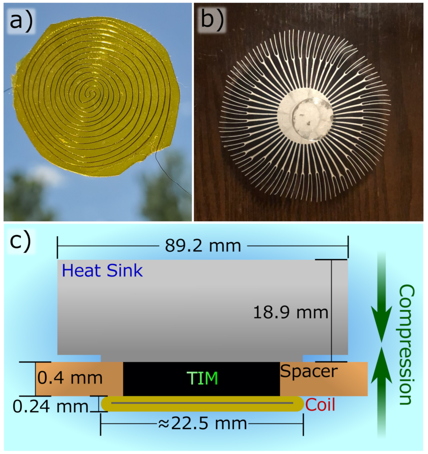
In place of a more complicated central processing unit with an at least somewhat variable heat output running Prime95 software, a custom coiled wire heater was used, shown in Figure 1a. This heating element employed a Nickel and Chromium alloy wire often used in electronics heating applications sandwiched between two pieces of Kapton tape. The wire used had a diameter of 72 () m, as measured by micrometer. Electrical current was driven through the coil by a programmable power supply (Chroma 62000P, Foothill Ranch, CA, USA) to produce Joule heating. The wire was hand-coiled by pinning a pre-cut length of wire down with tape onto a hard surface and carefully curling each end around the pinned central point until a roughly uniform coil was achieved. As small of a length of resistor wire extending out of the edge of the coil as possible was sought—typically around 1 cm—to reduce the fraction of heat that is generated outside of the coil. After, the tape with the coil stuck to its bottom side were carefully peeled from the hard surface and joined by another similar piece of tape to produce a completed heating element sandwich.
The heat sink was a stock unit sold in tandem with LGA-1155 socket processors, shown in Figure 1b, sourced directly from industry (Intel Corp. E97379-001, Santa Clara, CA, USA). To reduce experimental complexity and improve repeatability, the attached fan was removed. The heat sink was attached to TIM and heating coil in a passive cooling arrangement, resulting in increased thermal resistance, generating higher device temperatures than in an actively cooled setup, as intended by the product designers.
The polymer matrix used in the composite samples is a Diglycidyl ether of Bisphenol A (DGEBA) resin with a Triethylenetetramine hardening agent (Allied High Tech Products Inc., Rancho Dominguez, CA, USA) [73]. A curing polymer was chosen as a matrix for experimental ease and because a singular test would be conducted on each sample, rendering reliability concerns of a cured TIM negligible [74,75]. The FLG used in the composites has a vendor-specified lateral dimension of 25 m (XG Sciences, Lansing, MI, USA). First, an amount of resin is dispensed into a cup and subjected to a rough vacuum to draw out air bubbles and is then weighed on a scale. This weight is then used to calculate the amount of hardening agent to be used—12% of the weight of resin—and the FLG for a particular targeted filler level. Next, the FLG is added to the resin and the two are mixed in a bladeless, two axis planetary mixer (Flacktek Inc., Landrum, SC, USA) between 1500 and 2000 rpm, depending on difficulty mixing resultant from FLG load level, for 90 s. Then the hardening agent is added and mixed once more with the FLG-polymer mixture under similar conditions. Different TIM samples of DGEBA with FLG filler levels of 0 vol.%, 3.6 vol.%, 7.3 vol.%, 25.5 vol.%, and 43.6 vol.% were prepared. The composites of FLG filler concentrations above 7.3 vol.% were not further evaluated for experimentation, aside from SEM analysis, because of an inability to control their TIM bond line thickness as a result of the apparent increase in viscosity with increasing filler level, as quantitatively reported previously [76]. Work on similar composites has shown electrical conductivity of composites with total FLG-specific loading at around 7.3 vol.% should be on the order of magnitude of S/cm [54,77].
The mixed but still un-cured polymer composite is then placed on top of a heating coil that is pinned on two sides at the edge by spacers—copper metal sheets of 400 m thickness—that are themselves pinned by clamps, as shown in Figure 1c. The heat sink is then lowered onto the composite and heating coil and clamped down to compress the TIM and guarantee the eventual TIM thickness is defined by the spacers. It is this step in the process that closely mimics real-world industrial applications of TIMs that rendered the high load level FLG TIMs unusable in the present study. If the TIM apparent viscosity is low enough, excess composite material spills out the remaining two directions that are not occluded by the spacers. Special care was taken to ensure that there would be excess material so complete heater coverage is ensured. The clamped stack is then left to cure over night. After this, the spacers are carefully removed by pulling directly away from the cured TIM. The small resistance wire leads are soldered to a larger, less resistive wire with a length long enough to clear the overhang of the heat sink assembly, and finally that is alligator clipped to test cables connected to the power supply.
2.2. Experimental Procedure
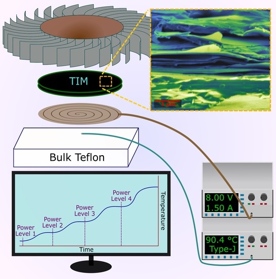
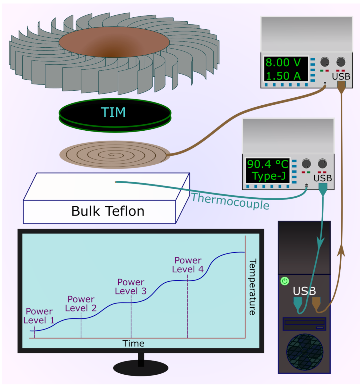
The heating coil, cured TIM, and heat sink assembly test vehicle is placed on top of a thermally insulating teflon plate with the coil side down in ambient atmosphere, shown in Figure 2. Between the teflon plate and the heating coil is a Type-J thermocouple (OMEGA Engineering, Inc., Norwalk, CT, USA) that probes the temperature of the heating coil itself, getting a direct measurement of coil temperature which is analogous to measuring the direct temperature of an electronic device. This entire vertical stack is lightly compressed in a clamp just enough to ensure the light thermocouple remains in place and in good contact. The clamp is imperfectly thermally isolated from the top of the heat sink with a small silicone pad insulation. The thermocouple was read with a voltmeter (Keithley 2182A, Solon, OH, USA). A computer running a python script retrieved temperature measurements from the voltmeter by passing standard commands for programmable instruments (SCPI) to it. In a similar fashion, the computer changed the coil heat dissipation rate via SCPI commands to the programmable power supply.
The experimental goal was to determine the equilibrium temperature of the heating coil at every investigated heat dissipation rate. This was done by applying a current through the heater, continually measuring the thermocouple temperature, and waiting for the time derivative of temperature to approach zero, accounting for measurement noise. Equilibrium was determined by comparing the most recent thermocouple temperature reading (), with previous recordings (), for likeness; the specific logical conditions are shown in Table 1. Additionally, a check to see if any of the previous four recordings were higher than the most recent—which could not occur without noise—was done to see if signal noise was a considerable factor in the most recent measurements so as to co-opt this unavoidable artifact as an indication of proximity to thermal equilibrium.
The heat at each step was calculated by the product of the pre-measured heating coil resistance and the square of the applied voltage. In this fashion, the power supply’s output current readings aren’t depended on for the determination of power output and is valid for invariant electrical loads. The heating coil’s resistance change is negligible because of Nickel-Chromium alloy wire’s very low resistivity dependence on the considered temperature range [78,79]. The areal heat density equivalent is trivially calculated by the heat power divided by the internal heating coil surface area, approximated as a true circle, disregarding Kapton tape borders that extend beyond the confines of the internal planar coil diameter. All prepared test vehicles’ coil circumferences were smaller than that of the heat sink mating surface.
Scanning Electron Microscopy (Carl Zeiss AG, Oberkochen, BW, DE, Gemini SEM) with an accelerating voltage of 2 kV, a working distance of 5 mm, and a secondary electron detector is conducted upon a composite’s post-cure, fractured surface. Raman experiments (Renishaw plc, Wotton-under-Edge, England, UK, InVia Raman) were conducted with an excitation wavelength of 633 in a backscattering configuration [80].
3. Results
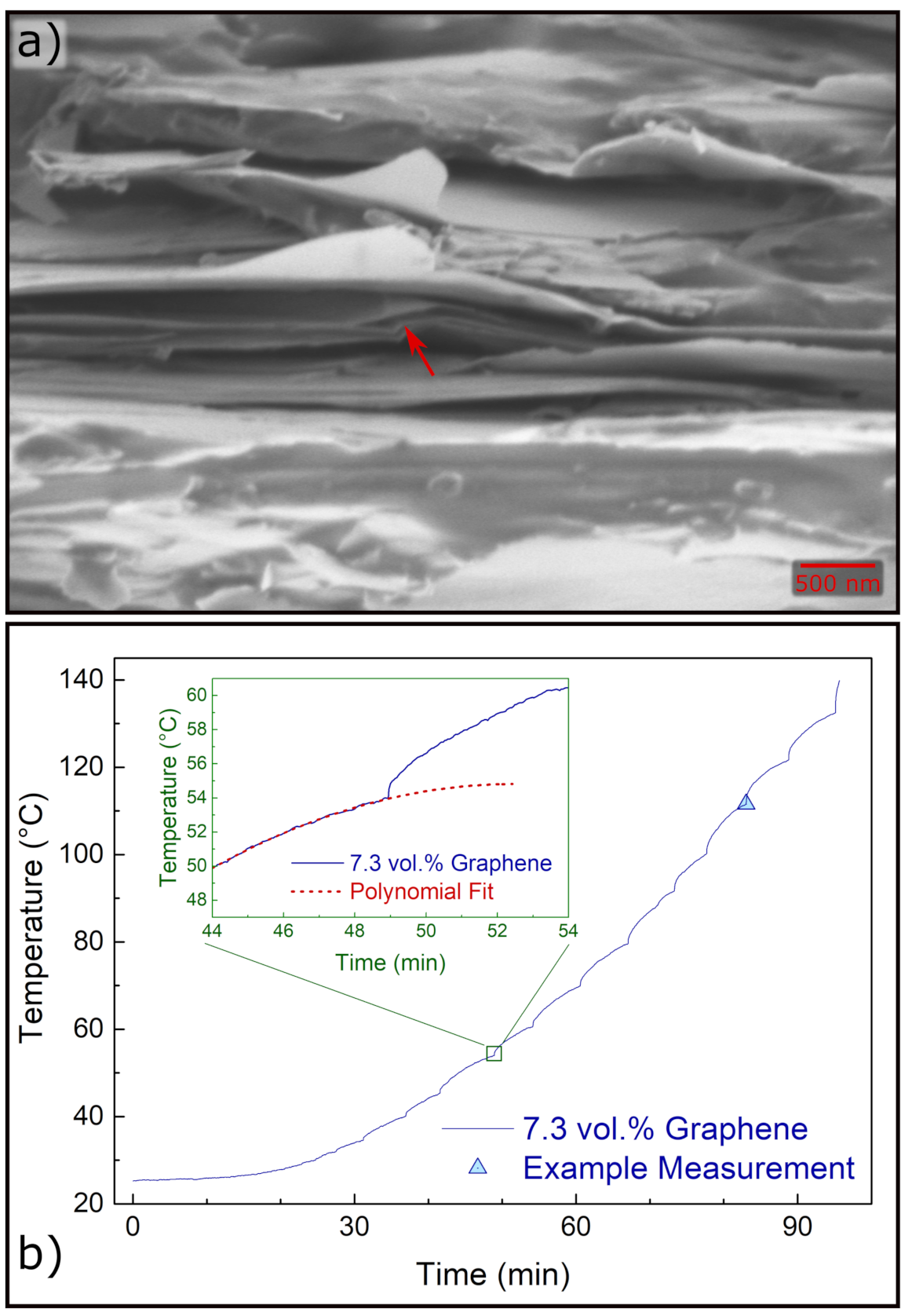
TIMs with high and low FLG concentration regimes were prepared. However, the high load level composites—25.5 and 43.6 vol.%—did not have a reliable TIM bond line thickness as a result of difficulty in compressing the composite to the spacer’s own thickness due to a vast apparent increase in composite viscosity. To apply enough pressure to clear excess high FLG concentration material inevitably removed the spacers from position. The 43.6 vol.% composite material was removed from the experimental vehicle to act as a representative SEM sample, albeit at a higher load level than the composites analyzed further. Figure 3a shows a SEM of this sample at high magnification in which either individual graphene sheets or stacks of FLG sheets thin enough to not be resolved by SEM are apparent in the middle of the micrograph, pointed to with an arrow. It is suggested from previous research that popular composite mixing processes could serve to further exfoliate FLG materials to smaller thicknesses [81]. Supplementary Figure S1 shows a SEM micrograph and Supplementary Figure S2 shows Raman results of a previous, identically prepared composite with a comparable FLG filling level of 5.4 vol.%.
Figure 3b contains the raw thermocouple readings over time of an experiment on the 7.3 vol.% FLG TIM. One can see in the data a continual, repeating process of rising temperature, then stabilizing temperature, followed by another period of quickly rising temperature. The power supply provides an electrical current and holds at that amount. The thermocouple continually reports its temperature and when the conditions set in Table 1 are met, the power supply increments to a higher current, repeating the process. One can particularly see from the inset plot in Figure 3b that the temperature does not fully reach equilibrium by the time the power level is increased once more. A polynomial fit of the readings prior to the next ramping cycle is extrapolated forward to give a qualitative idea how minor the under-estimation of equilibrium temperature and how much time is saved compared to getting to true equilibrium temperature. However, due to the predominately relative conditions the thermal equilibrium definition algorithm uses, this underestimation does increase at higher power levels. Put another way, , meaning that the condition will modestly loosen as the scale of temperature increases, as later recordings will. Supplementary Figure S3 shows differential scanning calorimetry results of pure DGEBA epoxy over typical electronic devices’ operating temperatures.
All temperature measurement techniques have a sensor time constant (), which is the time that must elapse for the sensor to read 63.2% of a step temperature change [82,83]. Typical sensor time constants for similar fine thermocouples of the vendor is ≈5 s in flowing water. Given that the thermocouple is pressed into a highly mechanically compliant, and thus great surface contact, polyimide film, in this application should be somewhat greater. The thermocouple reads 99.3% of a step change temperature at 5, giving a minimum time to read true temperature of ≈25 s. As a result, the raw data shown in Figure 3b is actually the temperature of the heating coil over time convoluted by the response characteristic of the thermocouple. Given the time scales between successive current ramping events (≈8 min average), it is clear that the majority of the observed behavior in Figure 3b is in fact a delayed temperature response of the heating coil itself and not purely the sensor heating up.
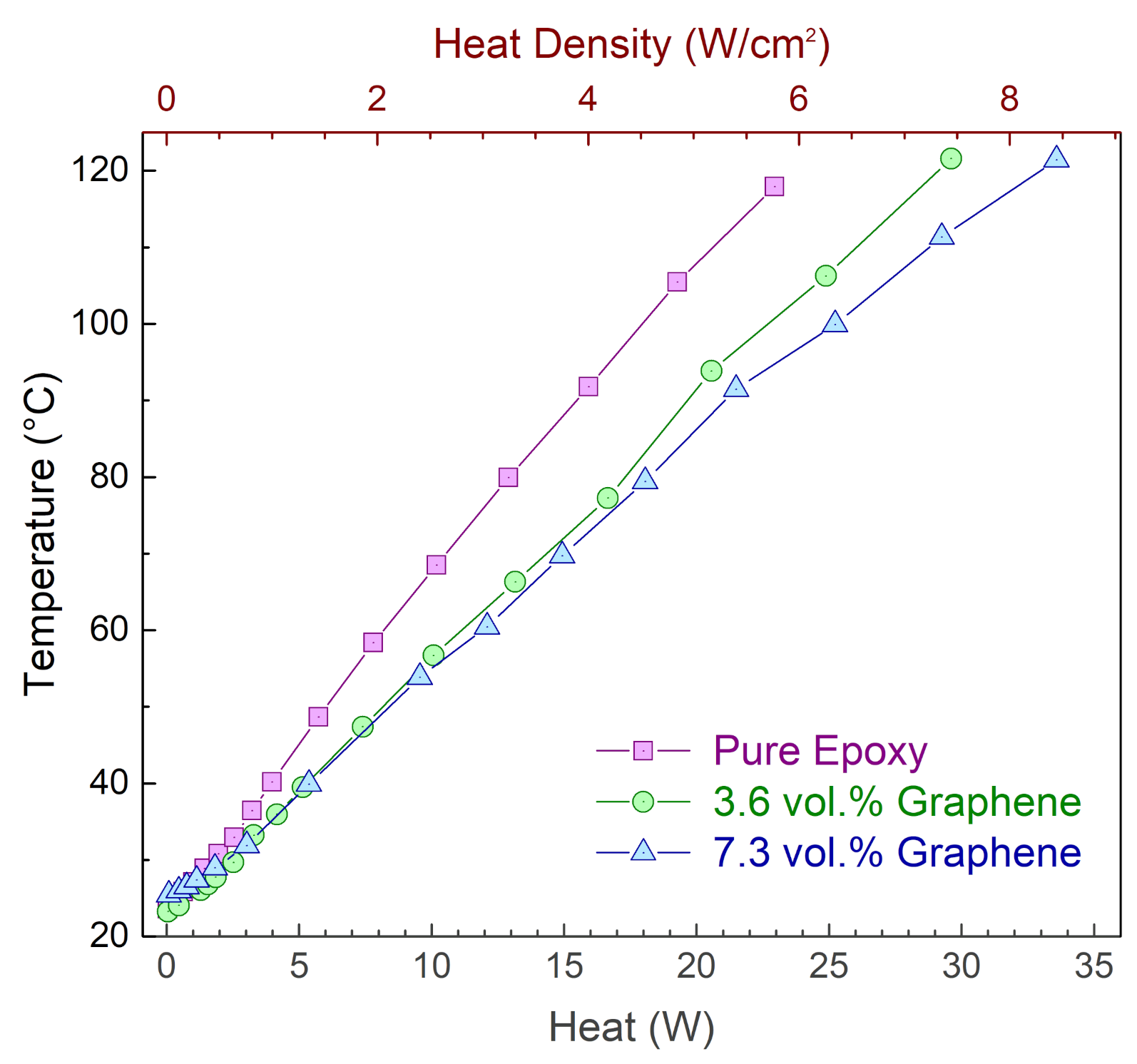
Recording the equilibrium temperature for the experimental vehicles with TIMs of DGEBA with FLG filler levels of 0 vol.%, 3.6 vol.%, and 7.3 vol.% showed that for comparable heating coil power levels increasing concentrations of FLG resulted in lower operating temperatures for the heating coil, as seen in Figure 4. At a total heat dissipation rate of 20 W, the operating temperatures were ≈108 C, ≈91 C, and ≈85 C for the 0 vol.%, 3.6 vol.%, and 7.3 vol.% samples, respectively. These operating temperatures correspond to a reduction in the increase of operating temperatures of 20% for the 3.6 vol.% TIM and 29% for the 7.3 vol.% TIM versus pure DGEBA. The modest non-linear behavior at the high power dissipation in the 7.3 vol.% data is attributed to the loosening of the conditions that define thermal equilibrium at higher temperatures, as discussed previously.
Most large logic chips will throttle down to a lower power state if their operating temperature reaches ≈100 C to prevent damage and unintended behavior. The passively-cooled test vehicles were able to dissipate ≈4.5 W, ≈5.7 W, and ≈6.4 W for 0 vol.%, 3.6 vol.%, and 7.3 vol.% TIMs, respectively, at typical throttling temperature. Table 2 shows the full least squares fits of equilibrium temperature () with respect to heat dissipation (q) as well as coefficient of determination for each TIM sample with intercepts fixed at the ambient room temperature at the time of each experiment.
The slopes of the least squares fitted lines corresponds to the combined thermal resistances of the TIM composites and passively cooled heat sinks. Increasing the FLG concentration from 0 vol.% to 7.3 vol.% decreased the thermal resistance from 4.23 C/W to 2.93 C/W. Alternatively, switching from 400 m of pure DGEBA to 7.3 vol.% of FLG in series with the heat sink decreased the thermal resistance by 1.3 C/W.
4. Discussion
The vast majority of research into TIMs consider the composite material properties which then provide the ability to calculate the junction thermal resistance [10]. In contrast, this work directly experimentally determines device equilibrium temperatures for different TIM materials inside of identical heat sink conditions at different device heat dissipation rates. Previous works have analyzed equilibrium temperatures of CPUs with different applied TIMs at similar computational loads [69,70,71,72]. However, this method has a few largely unaddressed limitations. CPU systems are complex, dynamic, and are difficult to simplify without a proprietary knowledge of design. A particular processor’s power consumption can vary even under identical computational loads due to gained efficiencies doing identical tasks in succession [84,85,86,87]. In addition, different architectures can compute tasks substantially differently leading to diminished repeatability among similar processors of different generations. Although a very minor factor, higher performance random access memory can lead to less processor idle time and more work done over time as a result. Moreover, heat generation takes place in predominately localized places that too also alter substantially over the course of architectural improvements, leaving which integrated CPU thermistor to trust as representative as overall processor temperature ambiguous [88]. This technique does indeed provide rough comparisons between different TIMs to determine relative performance, but no two seemingly identical CPU loads are in fact precisely so.
The results obtained are consistent with previous studies of both TIM material characterizations and comparative TIM CPU operating temperature studies in that increased FLG content, at least below a certain loading level at which point, improves TIM performance [31,34,37,39,54,69,70,72,89,90]. The present increase of TIM performance with additional FLG filler materials is a result of increasing the effective medium thermal conductivity at low filler levels. The FLG acts as discrete pathways for heat to flow through to a greater degree than it would through pure polymer. When the load level increases beyond a particular amount—termed the percolation threshold—the composite thermal conductivity increases precipitously as a result of developed direct pathways through the composite from filler to filler [91,92,93,94,95]. It should be noted that the percolation threshold was found in similar composites at higher load levels–above 20 vol.%–than in composites analyzed in the present study [37]. Recently, research has been conducted into thermal conductivity alterations over power cycles, very similar to the test conducted at present [96]. An increase in composite thermal conductivity—with accompanying reduction in thermal resistance—less than 5% could be expected in this composite as a result of the experiments.
These results provide the operating temperature of each test vehicle at a given, trustworthy heat dissipation level, made possible by the novel experimental technique. By removing the dependence on such a dynamic and complicated heating element as a CPU, greater control of output power is achieved. Real CPUs and similar graphics processing units vary in power output over an order of magnitude. Because of this, the ability to determine what an operating temperature should be anywhere in that heat dissipation range is useful for CPU designers and consumer electronics overall.
This study’s experimental design was focused on maximal control of variables. Using a TIM of a bond line thickness of 400 m is larger than those typically found in industry. This large bondline thickness makes the composite thermal conductivity of ever increasing importance and can minimize the contributions to thermal resistance of TIM-junction surface contact resistance. Recently, the trade-offs of TIM thickness and load level with subsequent composite thermal conductivity alterations was investigated in great detail using very similar composites finding lower thermal junction resistances in higher FLG concentration composites of the same thickness [97]. A thick bond line thickness was chosen in this study to render negligible on a relative basis any thickness measurement error. Additionally, CPU device heat dissipation solutions come with a fan to circulate air through the heat sink fins. To minimize complexity of reverse engineering multiple industrial CPU vendor fan angular velocities and conclude upon a representative fan speed versus operating temperature curve, a passive heat sink cooling set-up was used. Future research along a similar vein should focus on both smaller bond line thicknesses, <150 m, adding an active cooling fan with a realistic speed versus operating temperature behavior, and varying conditions of the mating surfaces.
5. Conclusions
This study provides a more direct, concrete understanding of the benefits that FLG TIMs provide to electronics products by way of a more streamlined and controllable experimental method than those often used in this vein of research. The results obtained were consistent with previous studies using different experimental methods. Increasing the FLG concentration from 0 vol.% to 7.3 vol.% decreased the TIM and passively-cooled heat sink thermal resistance from 4.23 C/W to 2.93 C/W. At a heat dissipation rate of 20 W, this reduced thermal resistance results in a reduction of operating temperature from ≈108 C down to ≈85 C. These results provide important context between research of FLG composite properties and industrial application.
Supplementary Materials
The following are available at https://0-www-mdpi-com.brum.beds.ac.uk/article/10.3390/c7030053/s1, Figure S1: 5.4 vol.% SEM micrograph, Figure S2: 5.4 vol.% Raman spectra, Figure S3: Pure DGEBA Differential Scanning Calorimetry results.
Funding
This research was conducted under financial assistance from the Graduate Assistance in Areas of National Need (GAANN) Fellowship.
Institutional Review Board Statement
Not applicable.
Informed Consent Statement
Not applicable.
Data Availability Statement
Not applicable.
Acknowledgments
Facilities and equipment for this study were generously provided by Alexander A. Balandin. Timothy Perrier’s assistance in setting up the experimental apparatus was appreciated greatly. The author is thankful towards Zahra Barani for useful discussions.
Conflicts of Interest
The authors declare no conflict of interest.
Abbreviations
The following abbreviations are used in this manuscript:
| TIM | Thermal interface material |
| FLG | few layer graphene |
| DGEBA | Diglycidyl ether of Bisphenol A |
| SCPI | standard commands for programmable instruments |
| Sensor time constant | |
| The experimental temperature recording x iterations previous to the most recent | |
| Least squares fit of equilibrium temperature as a function of applied heat | |
| q | Applied heat |
References
- Lewis, J.S. Thermal and Electrical Performance Control and Lifespan Progression of Graphene-Based Polymer Composites. Ph.D. Thesis, University of California-Riverside, Riverside, CA, USA, 2020. [Google Scholar]
- McCune, E. Fundamentals for Energy-Efficient Massive MIMO. In Proceedings of the 2017 IEEE Wireless Communications and Networking Conference Workshops (WCNCW), San Francisco, CA, USA, 19–22 March 2017; pp. 1–6. [Google Scholar] [CrossRef]
- Guo, A.; Del Alamo, J.A. Unified Mechanism for Positive-A nd Negative-Bias Temperature Instability in GaN MOSFETs. IEEE Trans. Electron Devices 2017, 64, 2142–2147. [Google Scholar] [CrossRef]
- Yu, Z.; Wang, R.; Hao, P.; Guo, S.; Ren, P.; Huang, R. Non-Universal Temperature Dependence of Hot Carrier Degradation (HCD) in FinFET: New Observations and Physical Understandings. In Proceedings of the 2018 IEEE Electron Devices Technology and Manufacturing Conference, EDTM 2018-Proceedings, Kobe, Japan, 13–16 March 2018; Institute of Electrical and Electronics Engineers Inc.: Manhattan, NY, USA, 2018; pp. 34–36. [Google Scholar] [CrossRef]
- Bury, E.; Chasin, A.; Kaczer, B.; Chuang, K.H.; Franco, J.; Simicic, M.; Weckx, P.; Linten, D. Self-heating-aware CMOS reliability characterization using degradation maps. In Proceedings of the IEEE International Reliability Physics Symposium Proceedings, Burlingame, CA, USA, 1–15 March 2018; Institute of Electrical and Electronics Engineers Inc.: Manhattan, NY, USA, 2018; Volume 2018, pp. 2A.31–2A.36. [Google Scholar] [CrossRef]
- Aslan, Y.; Kiper, C.E.; Johannes van den Biggelaar, A.; Johannsen, U.; Yarovoy, A. Passive Cooling of mm-Wave Active Integrated 5G Base Station Antennas Using CPU Heatsinks. In Proceedings of the 2019 16th European Radar Conference (EuRAD), Paris, France, 2–4 October 2019; pp. 121–124. [Google Scholar]
- Smoyer, J.L.; Norris, P.M. Brief Historical Perspective in Thermal Management and the Shift Toward Management at the Nanoscale. Heat Transf. Eng. 2019, 40, 269–282. [Google Scholar] [CrossRef]
- Saadah, M.; Hernandez, E.; Balandin, A. Thermal Management of Concentrated Multi-Junction Solar Cells with Graphene-Enhanced Thermal Interface Materials. Appl. Sci. 2017, 7, 589. [Google Scholar] [CrossRef] [Green Version]
- Mahadevan, B.K.; Naghibi, S.; Kargar, F.; Balandin, A.A. Non-Curing Thermal Interface Materials with Graphene Fillers for Thermal Management of Concentrated Photovoltaic Solar Cells. C J. Carbon Res. 2019, 6, 2. [Google Scholar] [CrossRef] [Green Version]
- Lewis, J.S.; Perrier, T.; Barani, Z.; Kargar, F.; Balandin, A.A. Thermal interface materials with graphene fillers: Review of the state of the art and outlook for future applications. Nanotechnology 2021, 32, 142003. [Google Scholar] [CrossRef] [PubMed]
- Wong, C.P.; Bollampally, R.S. Thermal conductivity, elastic modulus, and coefficient of thermal expansion of polymer composites filled with ceramic particles for electronic packaging. J. Appl. Polym. Sci. 1999, 74, 3396–3403. [Google Scholar] [CrossRef]
- Murshed, S.; Leong, K.; Yang, C. Enhanced thermal conductivity of TiO2—Water based nanofluids. Int. J. Therm. Sci. 2005, 44, 367–373. [Google Scholar] [CrossRef]
- Sim, L.; Ramanan, S.; Ismail, H.; Seetharamu, K.; Goh, T. Thermal characterization of Al2O3 and ZnO reinforced silicone rubber as thermal pads for heat dissipation purposes. Thermochim. Acta 2005, 430, 155–165. [Google Scholar] [CrossRef]
- Cola, B.A.; Xu, X.; Fisher, T.S. Increased real contact in thermal interfaces: A carbon nanotube/foil material. Appl. Phys. Lett. 2007, 90, 093513. [Google Scholar] [CrossRef]
- Zeng, J.; Cao, Z.; Yang, D.; Sun, L.; Zhang, L. Thermal conductivity enhancement of Ag nanowires on an organic phase change material. J. Therm. Anal. Calorim. 2009, 101, 385–389. [Google Scholar] [CrossRef]
- Yu, W.; Xie, H.; Li, Y.; Chen, L. Experimental investigation on thermal conductivity and viscosity of aluminum nitride nanofluid. Particuology 2011, 9, 187–191. [Google Scholar] [CrossRef]
- Gao, Z.; Zhao, L. Effect of nano-fillers on the thermal conductivity of epoxy composites with micro-Al2O3 particles. Mater. Des. 2015, 66, 176–182. [Google Scholar] [CrossRef]
- Burger, N.; Laachachi, A.; Mortazavi, B.; Ferriol, M.; Lutz, M.; Toniazzo, V.; Ruch, D. Alignments and network of graphite fillers to improve thermal conductivity of epoxy-based composites. Int. J. Heat Mass Transf. 2015, 89, 505–513. [Google Scholar] [CrossRef]
- Yu, W.; Zhao, J.; Wang, M.; Hu, Y.; Chen, L.; Xie, H. Thermal conductivity enhancement in thermal grease containing different CuO structures. Nanoscale Res. Lett. 2015, 10, 1–8. [Google Scholar] [CrossRef] [PubMed] [Green Version]
- Du, H.; Qi, Y.; Yu, W.; Yin, J.; Xie, H. T-shape ZnO whisker: A more effective thermal conductive filler than spherical particles for the thermal grease. Int. J. Heat Mass Transf. 2017, 112, 1052–1056. [Google Scholar] [CrossRef]
- Quinton, B.; Elston, L.; Scofield, J.; Mukhopadhyay, S. Aligned Carbon Nanotube Arrays Bonded to Solid Graphite Substrates: Thermal Analysis for Future Device Cooling Applications. C J. Carbon Res. 2018, 4, 28. [Google Scholar] [CrossRef] [Green Version]
- NarayanPrabhu, K. The effect of load and addition of MWCNTs on silicone based TIMs on thermal contact heat transfer across Cu/Cu interface. Mater. Res. Express 2019, 6, 1165h9. [Google Scholar] [CrossRef]
- Theerthagiri, J.; Salla, S.; Senthil, R.A.; Nithyadharseni, P.; Madankumar, A.; Arunachalam, P.; Maiyalagan, T.; Kim, H.S. A review on ZnO nanostructured materials: Energy, environmental and biological applications. Nanotechnology 2019, 30, 392001. [Google Scholar] [CrossRef] [PubMed]
- Sharma, V.; Kagdada, H.L.; Jha, P.K.; Śpiewak, P.; Kurzydłowski, K.J. Thermal transport properties of boron nitride based materials: A review. Renew. Sustain. Energy Rev. 2020, 120, 109622. [Google Scholar] [CrossRef]
- Balandin, A.A.; Ghosh, S.; Bao, W.; Calizo, I.; Teweldebrhan, D.; Miao, F.; Lau, C.N. Superior Thermal Conductivity of Single-Layer Graphene. Nano Lett. 2008, 8, 902–907. [Google Scholar] [CrossRef] [PubMed]
- Balandin, A.A. Thermal properties of graphene and nanostructured carbon materials. Nat. Mater. 2011, 10, 569–581. [Google Scholar] [CrossRef] [Green Version]
- Ghosh, S.; Calizo, I.; Teweldebrhan, D.; Pokatilov, E.P.; Nika, D.L.; Balandin, A.A.; Bao, W.; Miao, F.; Lau, C.N. Extremely high thermal conductivity of graphene: Prospects for thermal management applications in nanoelectronic circuits. Appl. Phys. Lett. 2008, 92, 151911. [Google Scholar] [CrossRef]
- Seol, J.H.; Jo, I.; Moore, A.L.; Lindsay, L.; Aitken, Z.H.; Pettes, M.T.; Li, X.; Yao, Z.; Huang, R.; Broido, D.; et al. Two-Dimensional Phonon Transport in Supported Graphene. Science 2010, 328, 213–216. [Google Scholar] [CrossRef] [PubMed] [Green Version]
- Cai, W.; Moore, A.L.; Zhu, Y.; Li, X.; Chen, S.; Shi, L.; Ruoff, R.S. Thermal transport in suspended and supported monolayer graphene grown by chemical vapor deposition. Nano Lett. 2010, 10, 1645–1651. [Google Scholar] [CrossRef] [PubMed]
- Wang, H.; Kurata, K.; Fukunaga, T.; Ago, H.; Takamatsu, H.; Zhang, X.; Ikuta, T.; Takahashi, K.; Nishiyama, T.; Takata, Y. Simultaneous measurement of electrical and thermal conductivities of suspended monolayer graphene. J. Appl. Phys. 2016, 119, 244306. [Google Scholar] [CrossRef]
- Zhang, P.; Zeng, J.; Zhai, S.; Xian, Y.; Yang, D.; Li, Q. Thermal Properties of Graphene Filled Polymer Composite Thermal Interface Materials. Macromol. Mater. Eng. 2017, 302, 1700068. [Google Scholar] [CrossRef]
- Li, A.; Zhang, C.; Zhang, Y.F. Thermal Conductivity of Graphene-Polymer Composites: Mechanisms, Properties, and Applications. Polymers 2017, 9, 437. [Google Scholar] [CrossRef] [Green Version]
- Balandin, A.A. Phononics of graphene and related materials. ACS Nano 2020, 14, 5170–5178. [Google Scholar] [CrossRef] [PubMed]
- Shahil, K.M.; Balandin, A.A. Graphene-multilayer graphene nanocomposites as highly efficient thermal interface materials. Nano Lett. 2012, 12, 861–867. [Google Scholar] [CrossRef] [Green Version]
- Fu, Y.X.; He, Z.X.; Mo, D.C.; Lu, S.S. Thermal conductivity enhancement of epoxy adhesive using graphene sheets as additives. Int. J. Therm. Sci. 2014, 86, 276–283. [Google Scholar] [CrossRef]
- Shtein, M.; Nadiv, R.; Buzaglo, M.; Regev, O. Graphene-Based Hybrid Composites for Efficient Thermal Management of Electronic Devices. Acs Appl. Mater. Interfaces 2015, 7, 23725–23730. [Google Scholar] [CrossRef] [PubMed]
- Kargar, F.; Barani, Z.; Salgado, R.; Debnath, B.; Lewis, J.S.; Aytan, E.; Lake, R.K.; Balandin, A.A. Thermal Percolation Threshold and Thermal Properties of Composites with High Loading of Graphene and Boron Nitride Fillers. ACS Appl. Mater. Interfaces 2018, 10, 37555–37565. [Google Scholar] [CrossRef] [PubMed]
- Kargar, F.; Barani, Z.; Balinskiy, M.; Magana, A.S.; Lewis, J.S.; Balandin, A.A. Dual-Functional Graphene Composites for Electromagnetic Shielding and Thermal Management. Adv. Electron. Mater. 2019, 5, 1800558. [Google Scholar] [CrossRef] [Green Version]
- Naghibi, S.; Kargar, F.; Wright, D.; Huang, C.Y.T.; Mohammadzadeh, A.; Barani, Z.; Salgado, R.; Balandin, A.A. Noncuring Graphene Thermal Interface Materials for Advanced Electronics. Adv. Electron. Mater. 2020, 1901303. [Google Scholar] [CrossRef]
- Biercuk, M.J.; Llaguno, M.C.; Radosavljevic, M.; Hyun, J.K.; Johnson, A.T.; Fischer, J.E. Carbon nanotube composites for thermal management. Appl. Phys. Lett. 2002, 80, 2767–2769. [Google Scholar] [CrossRef]
- Martin, C.; Sandler, J.; Shaffer, M.; Schwarz, M.K.; Bauhofer, W.; Schulte, K.; Windle, A. Formation of percolating networks in multi-wall carbon-nanotube—Epoxy composites. Compos. Sci. Technol. 2004, 64, 2309–2316. [Google Scholar] [CrossRef]
- Stankovich, S.; Dikin, D.A.; Dommett, G.H.; Kohlhaas, K.M.; Zimney, E.J.; Stach, E.A.; Piner, R.D.; Nguyen, S.B.T.; Ruoff, R.S. Graphene-based composite materials. Nature 2006, 442, 282–286. [Google Scholar] [CrossRef]
- Pang, H.; Chen, T.; Zhang, G.; Zeng, B.; Li, Z.M. An electrically conducting polymer/graphene composite with a very low percolation threshold. Mater. Lett. 2010, 64, 2226–2229. [Google Scholar] [CrossRef]
- Zhang, H.B.; Zheng, W.G.; Yan, Q.; Yang, Y.; Wang, J.W.; Lu, Z.H.; Ji, G.Y.; Yu, Z.Z. Electrically conductive polyethylene terephthalate/graphene nanocomposites prepared by melt compounding. Polymer 2010, 51, 1191–1196. [Google Scholar] [CrossRef]
- Potts, J.R.; Dreyer, D.R.; Bielawski, C.W.; Ruoff, R.S. Graphene-based polymer nanocomposites. Polymer 2011, 52, 5–25. [Google Scholar] [CrossRef] [Green Version]
- Wang, Q.; Gao, W.; Xie, Z. Highly thermally conductive room-temperature-vulcanized silicone rubber and silicone grease. J. Appl. Polym. Sci. 2003, 89, 2397–2399. [Google Scholar] [CrossRef]
- Yu, A.; Ramesh, P.; Sun, X.; Bekyarova, E.; Itkis, M.E.; Haddon, R.C. Enhanced Thermal Conductivity in a Hybrid Graphite Nanoplatelet—Carbon Nanotube Filler for Epoxy Composites. Adv. Mater. 2008, 20, 4740–4744. [Google Scholar] [CrossRef]
- Zhou, T.; Wang, X.; Liu, X.; Xiong, D. Improved thermal conductivity of epoxy composites using a hybrid multi-walled carbon nanotube/micro-SiC filler. Carbon 2010, 48, 1171–1176. [Google Scholar] [CrossRef]
- Li, T.L.; Hsu, S.L.C. Enhanced Thermal Conductivity of Polyimide Films via a Hybrid of Micro- and Nano-Sized Boron Nitride. J. Phys. Chem. B 2010, 114, 6825–6829. [Google Scholar] [CrossRef]
- Kemaloglu, S.; Ozkoc, G.; Aytac, A. Properties of thermally conductive micro and nano size boron nitride reinforced silicon rubber composites. Thermochim. Acta 2010, 499, 40–47. [Google Scholar] [CrossRef]
- Yang, K.; Gu, M. Enhanced thermal conductivity of epoxy nanocomposites filled with hybrid filler system of triethylenetetramine-functionalized multi-walled carbon nanotube/silane-modified nano-sized silicon carbide. Compos. Part A Appl. Sci. Manuf. 2010, 41, 215–221. [Google Scholar] [CrossRef]
- Pak, S.Y.; Kim, H.M.; Kim, S.Y.; Youn, J.R. Synergistic improvement of thermal conductivity of thermoplastic composites with mixed boron nitride and multi-walled carbon nanotube fillers. Carbon 2012, 50, 4830–4838. [Google Scholar] [CrossRef]
- Teng, C.C.; Ma, C.C.M.; Chiou, K.C.; Lee, T.M. Synergetic effect of thermal conductive properties of epoxy composites containing functionalized multi-walled carbon nanotubes and aluminum nitride. Compos. Part B Eng. 2012, 43, 265–271. [Google Scholar] [CrossRef]
- Lewis, J.S.; Barani, Z.; Magana, A.S.; Kargar, F.; Balandin, A.A. Thermal and electrical conductivity control in hybrid composites with graphene and boron nitride fillers. Mater. Res. Express 2019, 6, 085325. [Google Scholar] [CrossRef] [Green Version]
- Yang, S.Y.; Lin, W.N.; Huang, Y.L.; Tien, H.W.; Wang, J.Y.; Ma, C.C.M.; Li, S.M.; Wang, Y.S. Synergetic effects of graphene platelets and carbon nanotubes on the mechanical and thermal properties of epoxy composites. Carbon 2011, 49, 793–803. [Google Scholar] [CrossRef]
- Ma, A.-j.; Chen, W.; Hou, Y. Enhanced Thermal Conductivity of Epoxy Composites with MWCNTs/AlN Hybrid Filler. Polym. Plast. Technol. Eng. 2012, 51, 1578–1582. [Google Scholar] [CrossRef]
- Yu, L.; Park, J.S.; Lim, Y.S.; Lee, C.S.; Shin, K.; Moon, H.J.; Yang, C.M.; Lee, Y.S.; Han, J.H. Carbon hybrid fillers composed of carbon nanotubes directly grown on graphene nanoplatelets for effective thermal conductivity in epoxy composites. Nanotechnology 2013, 24, 155604. [Google Scholar] [CrossRef] [PubMed]
- Fang, X.; Fan, L.W.; Ding, Q.; Wang, X.; Yao, X.L.; Hou, J.F.; Yu, Z.T.; Cheng, G.H.; Hu, Y.C.; Cen, K.F. Increased thermal conductivity of eicosane-based composite phase change materials in the presence of graphene nanoplatelets. Energy Fuels 2013, 27, 4041–4047. [Google Scholar] [CrossRef]
- Goli, P.; Legedza, S.; Dhar, A.; Salgado, R.; Renteria, J.; Balandin, A.A. Graphene-enhanced hybrid phase change materials for thermal management of Li-ion batteries. J. Power Sources 2014, 248, 37–43. [Google Scholar] [CrossRef] [Green Version]
- Prolongo, S.G.; Moriche, R.; Jiménez-Suárez, A.; Sánchez, M.; Ureña, A. Epoxy Adhesives Modified with Graphene for Thermal Interface Materials. J. Adhes. 2014, 90, 835–847. [Google Scholar] [CrossRef]
- Zhang, P.; Li, Q.; Xuan, Y. Thermal contact resistance of epoxy composites incorporated with nano-copper particles and the multi-walled carbon nanotubes. Compos. Part A Appl. Sci. Manuf. 2014, 57, 1–7. [Google Scholar] [CrossRef]
- Olowojoba, G.B.; Eslava, S.; Gutierrez, E.S.; Kinloch, A.J.; Mattevi, C.; Rocha, V.G.; Taylor, A.C. In situ thermally reduced graphene oxide/epoxy composites: Thermal and mechanical properties. Appl. Nanosci. 2016, 6, 1015–1022. [Google Scholar] [CrossRef]
- Lian, G.; Tuan, C.C.; Li, L.; Jiao, S.; Wang, Q.; Moon, K.S.; Cui, D.; Wong, C.P. Vertically Aligned and Interconnected Graphene Networks for High Thermal Conductivity of Epoxy Composites with Ultralow Loading. Chem. Mater. 2016, 28, 6096–6104. [Google Scholar] [CrossRef]
- Moriche, R.; Prolongo, S.; Sánchez, M.; Jiménez-Suárez, A.; Chamizo, F.; Ureña, A. Thermal conductivity and lap shear strength of GNP/epoxy nanocomposites adhesives. Int. J. Adhes. Adhes. 2016, 68, 407–410. [Google Scholar] [CrossRef]
- Huang, T.; Zeng, X.; Yao, Y.; Sun, R.; Meng, F.; Xu, J.; Wong, C. Boron nitride@graphene oxide hybrids for epoxy composites with enhanced thermal conductivity. RSC Adv. 2016, 6, 35847–35854. [Google Scholar] [CrossRef]
- Yuan, C.; Xie, B.; Huang, M.; Wu, R.; Luo, X. Thermal conductivity enhancement of platelets aligned composites with volume fraction from 10% to 20%. Int. J. Heat Mass Transf. 2016, 94, 20–28. [Google Scholar] [CrossRef]
- Zhao, Y.H.; Zhang, Y.F.; Wu, Z.K.; Bai, S.L. Synergic enhancement of thermal properties of polymer composites by graphene foam and carbon black. Compos. Part B Eng. 2016, 84, 52–58. [Google Scholar] [CrossRef]
- Dmitriev, A.A.; Dmitriev, A.S.; Makarov, P.; Mikhailova, I. New nanocomposite surfaces and thermal interface materials based on mesoscopic microspheres, polymers and graphene flakes. AIP Conf. Proc. 2018, 1957, 020003. [Google Scholar] [CrossRef]
- Renteria, J.; Legedza, S.; Salgado, R.; Balandin, M.; Ramirez, S.; Saadah, M.; Kargar, F.; Balandin, A. Magnetically-functionalized self-aligning graphene fillers for high-efficiency thermal management applications. Mater. Des. 2015, 88, 214–221. [Google Scholar] [CrossRef] [Green Version]
- Suh, D.; Moon, C.M.; Kim, D.; Baik, S. Ultrahigh Thermal Conductivity of Interface Materials by Silver-Functionalized Carbon Nanotube Phonon Conduits. Adv. Mater. 2016, 28, 7220–7227. [Google Scholar] [CrossRef]
- Dmitriev, A.S.; Valeev, A.R. Graphene nanocomposites as thermal interface materials for cooling energy devices. J. Phys. Conf. Ser. 2017, 891, 012359. [Google Scholar] [CrossRef] [Green Version]
- Mai, P.T.; Bui, T.A.; Van Tran, H.; Van Pham, T.; Nguyen, D.N.; Phan, M.N.; Bui, T.H. Application of Graphene Silicone Grease in heat dissipation for the Intel Core i5 Processor. JOIV Int. J. Informatics Vis. 2019, 3, 222–226. [Google Scholar] [CrossRef] [Green Version]
- Plazek, D.J.; Choy, I.C. The physical properties of bisphenol-a-based epoxy resins during and after curing. II. Creep behavior above and below the glass transition temperature. J. Polym. Sci. Part B Polym. Phys. 1989, 27, 307–324. [Google Scholar] [CrossRef]
- Prasher, R.; Matayabas, J. Thermal contact resistance of cured gel polymeric thermal interface material. IEEE Trans. Compon. Packag. Technol. 2004, 27, 702–709. [Google Scholar] [CrossRef]
- Due, J.; Robinson, A.J. Reliability of thermal interface materials: A review. Appl. Therm. Eng. 2013, 50, 455–463. [Google Scholar] [CrossRef]
- Naghibi, S. Noncuring Graphene Thermal Interface Materials for Advanced Electronics. Ph.D. Thesis, University of California-Riverside, Riverside, CA, USA, 2020. [Google Scholar]
- Nouri-Borujerdi, A.; Kazemi-Ranjbar, S. Thermal and electrical conductivity of a graphene-based hybrid filler epoxy composite. J. Mater. Sci. 2021, 56, 15151–15161. [Google Scholar] [CrossRef]
- Arnold, A. Nickel-chromium-aluminium-copper resistance wire. Proc. IEE Part B Radio Electron. Eng. 1956, 103, 439–447. [Google Scholar] [CrossRef]
- Yao, Y.; Arajs, S.; Anderson, E. Electrical resistivity of nickel-rich nickel-chromium alloys between 4 and 300 K. J. Low Temp. Phys. 1975, 21, 369–376. [Google Scholar] [CrossRef]
- Shahil, K.M.F.; Hossain, M.Z.; Goyal, V.; Balandin, A.A. Micro-Raman spectroscopy of mechanically exfoliated few-quintuple layers of Bi2Te3, Bi2Se3, and Sb2Te3 materials. J. Appl. Phys. 2012, 111, 054305. [Google Scholar] [CrossRef] [Green Version]
- Paton, K.R.; Varrla, E.; Backes, C.; Smith, R.J.; Khan, U.; O’Neill, A.; Boland, C.; Lotya, M.; Istrate, O.M.; King, P.; et al. Scalable production of large quantities of defect-free few-layer graphene by shear exfoliation in liquids. Nat. Mater. 2014, 13, 624–630. [Google Scholar] [CrossRef] [PubMed]
- Henning, C.; Parker, R. Transient response of an intrinsic thermocouple. J. Heat Transf. 1967, 89, 146–152. [Google Scholar] [CrossRef]
- Farahmand, K.; Kaufman, J.W. Experimental measurement of fine thermocouple response time in air. Exp. Heat Transf. 2001, 14, 107–118. [Google Scholar] [CrossRef]
- Yang, L.; Dick, R.P.; Memik, G.; Dinda, P. HAPPE: Human and Application-Driven Frequency Scaling for Processor Power Efficiency. IEEE Trans. Mob. Comput. 2013, 12, 1546–1557. [Google Scholar] [CrossRef] [Green Version]
- Podzimek, A.; Bulej, L.; Chen, L.Y.; Binder, W.; Tuma, P. Analyzing the Impact of CPU Pinning and Partial CPU Loads on Performance and Energy Efficiency. In Proceedings of the 2015 15th IEEE/ACM International Symposium on Cluster, Cloud and Grid Computing, Shenzhen, China, 4–7 May 2015; pp. 1–10. [Google Scholar] [CrossRef]
- Travers, M. Cpu Power Consumption Experiments and Results Analysis of Intel i7-4820k; Technical Report; Newcastle University: Newcastle upon Tyne, UK, 2015. [Google Scholar]
- Rumi, M.A.; Hasibul Hasan, D.M. CPU power consumption reduction in android smartphone. In Proceedings of the 2015 3rd International Conference on Green Energy and Technology (ICGET), Dhaka, Bangladesh, 11 September 2015; pp. 1–6. [Google Scholar] [CrossRef]
- Zajac, P.; Janicki, M.; Szermer, M.; Napieralski, A. Evaluating the impact of scaling on temperature in FinFET-technology multicore processors. Microelectron. J. 2014, 45, 1806–1813. [Google Scholar] [CrossRef]
- Tang, B.; Hu, G.; Gao, H.; Hai, L. Application of graphene as filler to improve thermal transport property of epoxy resin for thermal interface materials. Int. J. Heat Mass Transf. 2015, 85, 420–429. [Google Scholar] [CrossRef]
- Zhang, Y.; Zhang, M. Behavior of a graphene/epoxy composite used as thermal interface material for LED heat dissipation. Mater. Test. 2017, 59, 1037–1042. [Google Scholar] [CrossRef]
- Shenogina, N.; Shenogin, S.; Xue, L.; Keblinski, P. On the lack of thermal percolation in carbon nanotube composites. Appl. Phys. Lett. 2005, 87, 133106. [Google Scholar] [CrossRef] [Green Version]
- Bonnet, P.; Sireude, D.; Garnier, B.; Chauvet, O. Thermal properties and percolation in carbon nanotube-polymer composites. Appl. Phys. Lett. 2007, 91, 201910. [Google Scholar] [CrossRef]
- Zheng, R.; Gao, J.; Wang, J.; Feng, S.P.; Ohtani, H.; Wang, J.; Chen, G. Thermal percolation in stable graphite suspensions. Nano Lett. 2012, 12, 188–192. [Google Scholar] [CrossRef] [PubMed]
- Gu, J.; Xie, C.; Li, H.; Dang, J.; Geng, W.; Zhang, Q. Thermal percolation behavior of graphene nanoplatelets/polyphenylene sulfide thermal conductivity composites. Polym. Compos. 2014, 35, 1087–1092. [Google Scholar] [CrossRef]
- Shtein, M.; Nadiv, R.; Buzaglo, M.; Kahil, K.; Regev, O. Thermally conductive graphene-polymer composites: Size, percolation, and synergy effects. Chem. Mater. 2015, 27, 2100–2106. [Google Scholar] [CrossRef]
- Lewis, J.S.; Perrier, T.; Mohammadzadeh, A.; Kargar, F.; Balandin, A.A. Power Cycling and Reliability Testing of Epoxy-Based Graphene Thermal Interface Materials. C J. Carbon Res. 2020, 6, 26. [Google Scholar] [CrossRef]
- Sudhindra, S.; Kargar, F.; Balandin, A.A. Noncured Graphene Thermal Interface Materials for High-Power Electronics: Minimizing the Thermal Contact Resistance. Nanomaterials 2021, 11, 1699. [Google Scholar] [CrossRef] [PubMed]
Figure 1.
(a) Close-up picture of a representative custom heating coil used for experimentation. (b) A top-down picture of a CPU heat sink, with thermal interface mating surface face down, with imperfections from previous use. (c) A schematic of the sample fabrication process with relevant dimensions marked.

Figure 2.
Schematic of the experimental procedure. The heating coil that is bonded to the heat sink by the TIM is placed on top of a thermocouple and teflon insulator. The computer continually reads thermocouple and changes the power supply’s current to the heating coil when certain conditions are met.

Figure 3.
(a) Pseudo-colored SEM of a representative FLG composite with an arrow pointing to a definite FLG flake. (b) Thermocouple temperature readings over time in the course of an experiment.
Figure 3.
(a) Pseudo-colored SEM of a representative FLG composite with an arrow pointing to a definite FLG flake. (b) Thermocouple temperature readings over time in the course of an experiment.

Figure 4.
Measured thermal equilibria for each experimental vehicle with different TIM FLG concentrations at different heating coil power levels.
Figure 4.
Measured thermal equilibria for each experimental vehicle with different TIM FLG concentrations at different heating coil power levels.


Table 1.
The set of conditions that define equilibrium temperature at a given heat dissipation level, where is the temperature recording x iterations back from the most recent measurement, .
Table 1.
The set of conditions that define equilibrium temperature at a given heat dissipation level, where is the temperature recording x iterations back from the most recent measurement, .
| Measurement Position | Condition |
|---|---|
| 1–4 previous | , or , or , or |
| 5 previous | |
| 10 previous | |
| 20 previous | |
| 30 previous |
Table 2.
Linear dependence of equilibrium temperature () on heat dissipation (q) with a fixed intercept at the ambient room temperature at the time of experiment for each TIM loading level.
Table 2.
Linear dependence of equilibrium temperature () on heat dissipation (q) with a fixed intercept at the ambient room temperature at the time of experiment for each TIM loading level.
| TIM Load Level | Least Squares Fit | |
|---|---|---|
| 0 vol.% | 0.9996 | |
| 3.6 vol.% | 0.9998 | |
| 7.3 vol.% | 0.9995 |
Publisher’s Note: MDPI stays neutral with regard to jurisdictional claims in published maps and institutional affiliations. |
© 2021 by the author. Licensee MDPI, Basel, Switzerland. This article is an open access article distributed under the terms and conditions of the Creative Commons Attribution (CC BY) license (https://creativecommons.org/licenses/by/4.0/).
Share and Cite
MDPI and ACS Style
Lewis, J.S. Reduction of Device Operating Temperatures with Graphene-Filled Thermal Interface Materials. C 2021, 7, 53. https://0-doi-org.brum.beds.ac.uk/10.3390/c7030053
AMA Style
Lewis JS. Reduction of Device Operating Temperatures with Graphene-Filled Thermal Interface Materials. C. 2021; 7(3):53. https://0-doi-org.brum.beds.ac.uk/10.3390/c7030053
Chicago/Turabian StyleLewis, Jacob S. 2021. "Reduction of Device Operating Temperatures with Graphene-Filled Thermal Interface Materials" C 7, no. 3: 53. https://0-doi-org.brum.beds.ac.uk/10.3390/c7030053
Note that from the first issue of 2016, this journal uses article numbers instead of page numbers. See further details here.