
Geometrically Constrained Skyrmions


CNRS, Institut de Physique et Chimie des Matériaux de Strasbourg, Université de Strasbourg, UMR 7504, F-67000 Strasbourg, France
*
Author to whom correspondence should be addressed.
Magnetochemistry 2021, 7(2), 26; https://0-doi-org.brum.beds.ac.uk/10.3390/magnetochemistry7020026
Submission received: 15 January 2021
/
Revised: 1 February 2021
/
Accepted: 4 February 2021
/
Published: 12 February 2021
(This article belongs to the Special Issue Recent Advances in Nanomagnetism)
Abstract
:Skyrmions are chiral swirling magnetization structures with nanoscale size. These structures have attracted considerable attention due to their topological stability and promising applicability in nanodevices, since they can be displaced with spin-polarized currents. However, for the comprehensive implementation of skyrmions in devices, it is imperative to also attain control over their geometrical position. Here we show that, through thickness modulations introduced in the host material, it is possible to constrain three-dimensional skyrmions to desired regions. We investigate skyrmion structures in rectangular FeGe platelets with micromagnetic finite element simulations. First, we establish a phase diagram of the minimum-energy magnetic state as a function of the external magnetic field strength and the film thickness. Using this understanding, we generate preferential sites for skyrmions in the material by introducing dot-like “pockets” of reduced film thickness. We show that these pockets can serve as pinning centers for the skyrmions, thus making it possible to obtain a geometric control of the skyrmion position. This control allows for stabilization of skyrmions at positions and in configurations that they would otherwise not attain. Our findings may have implications for technological applications in which skyrmions are used as units of information that are displaced along racetrack-type shift register devices.
1. Introduction
Magnetic skyrmions, predicted by theory almost 30 years ago, have advanced to a central topic of research [1,2,3] in nanoscale magnetism over the last decade following their experimental observation [4,5]. Their particular topological properties [6], which impart them high stability and particle-like behavior [7,8,9], combined with their room-temperature availability [10,11], reduced dimensions [12], and their unique dynamic properties [13], render these magnetic structures promising candidates for future spintronic applications [14]. Skyrmions are formed in non-centrosymmetric magnetic materials exhibiting a sufficiently strong Dzyaloshinsky–Moriya Interaction (DMI) [4,5,15], that is, an antisymmetric energy term that favors the arrangement of the magnetization in helical spin structures with a specific handedness and spiral period. In extended thin films, in addition to the DMI, the formation and stability of skyrmions depends sensitively on various parameters, such as the strength of an externally applied magnetic field, the film thickness, temperature, and the magnetic history of the sample. Phase diagrams have been reported in the literature [10,16,17,18], displaying the parameter ranges within which skyrmions are stable and where they may take different forms. Skyrmions may typically either develop individually or in the form of a hexagonal skyrmion lattice. While the occurrence of individual skyrmions makes them attractive candidates for units of information that can be displaced in a controlled way by spin-polarized electric currents, their spontaneous arrangement in the form of a periodic lattice could be interesting for magnonic applications [19], where these point-like magnetic structures could play the role of scattering centers of planar spin waves. One drawback of possible applications of skyrmions is the difficulty of controlling their position. For instance, if skyrmions are to be used as units of information in race-track-type shift-register devices, it is not only necessary to be able to displace them in a controlled way, but also to make sure that they are shifted between well-defined positions along the track. In domain-wall-based concepts for race-track memory devices [20], which preceded the skyrmion-based variants, this control of the position was typically achieved by inserting indentations (“notches”) into the strips [21,22]. It was shown that such notches represent preferential sites for domain walls, making it possible to trap domain walls at these specific positions, from which they could only be detached after overcoming a certain depinning energy [23]. Although the possibility to capture skyrmions at specific sites has been addressed in the case of ultrathin films, geometric control analogous to the pinning of domain walls at notches does not yet seem to be firmly established for skyrmions. In a recent study, Suess and coworkers reported that skyrmions could be pinned in a racetrack-type geometry by introducing semicircular notches at the lateral boundaries [24]. However, the authors also found that skyrmions have a tendency to lose their topological stability and to dissolve when they interact with these notches. In two-dimensional systems, strategies for the pinning of skyrmions include the insertion of point-like defects [25,26] or atomic-scale vacancies [27]. Remarkably, randomly distributed point defects in ultrathin films have also been reported to have little effect on the current-driven skyrmion dynamics [7]. Motivated to further the discussion on this topic by addressing the three-dimensional case of “bulk” DMI, we use finite-element micromagnetic simulations to study the extent to which geometric control of the skyrmion position in a thin-film element can be achieved by introducing a patterning in the form of local variations of the film thickness. Compared to holes or lateral notches, these geometric features have the advantage of preserving the topological stability of skyrmions interacting with them. Our simulations show that, by locally lowering the film thickness in sub-micron-sized, dot-shaped regions, skyrmions can in fact be “captured” at these geometrically defined sites. We find that, by using geometrical constrains of this type, skyrmions can be stabilized at positions that they would otherwise not adopt. For instance, these geometric manipulations make it possible to generate regular, square lattices of skyrmions which, apart from exceptional situations [28], are not observed naturally in non-centrosymmetric ferromagnets. It is argued that this control of skyrmion positions in magnetic thin films can open up new possibilities for skyrmionic devices, as well as for concepts of magnonic metamaterials.
2. Results
Before addressing the question of how preferential sites for skyrmions can be generated through nanopatterning, we first investigate, as a preliminary study, the field- and thickness dependence of skyrmionic structures forming in rectangular FeGe platelets.
2.1. Chiral Magnetization States in a Helimagnetic Rectangular Platelet
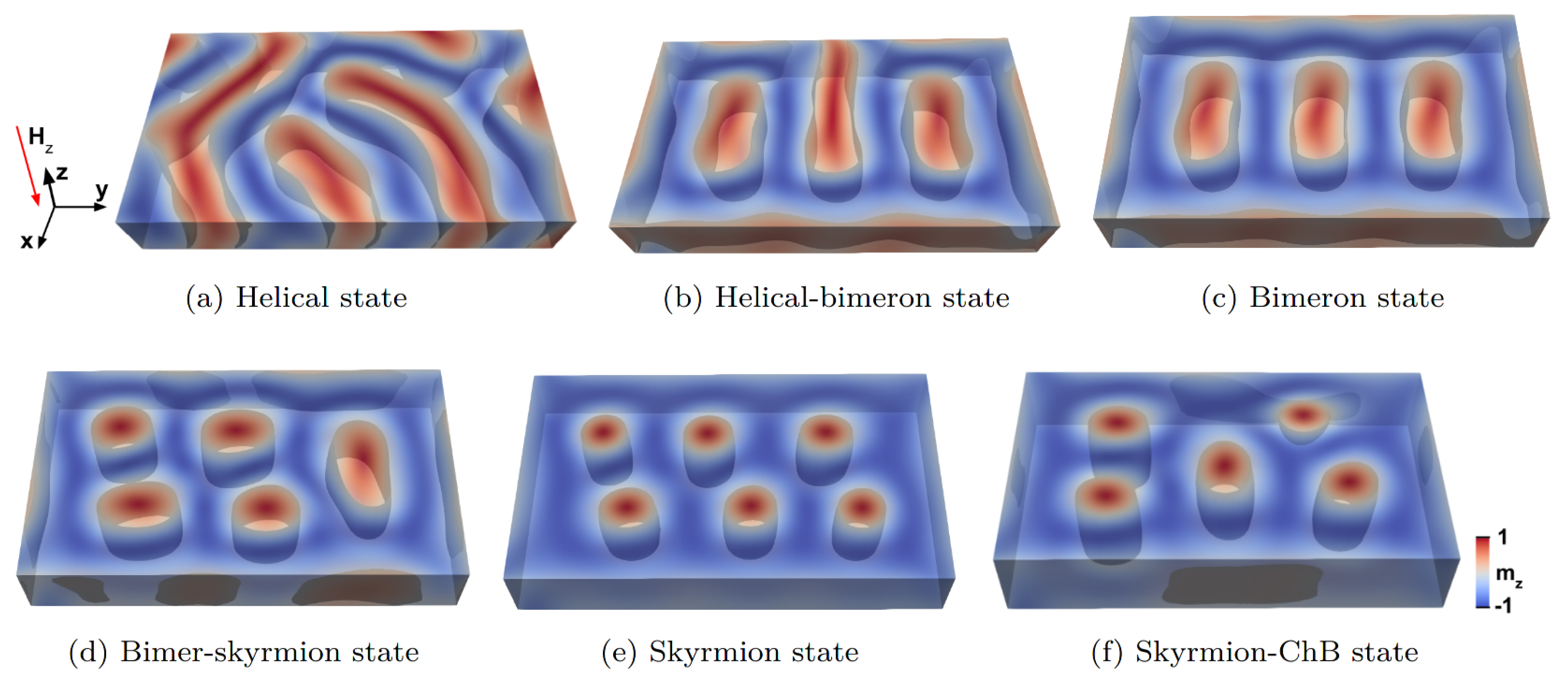
We consider rectangular thin-film elements with a lateral size of and thicknesses ranging between 5 and 75 , and simulate the magnetic structures forming in the presence of a perpendicular external magnetic field with a flux density varying between 0 and 900 . The simulations yield a large variety of possible magnetization states in this thickness and field range, which can be classified into six non-trivial types, summarized in Figure 1. The three main types are the helical state shown in panel (a), which is characterized by the presence of regular spin spirals extending over large parts of the sample, the bimeron state (c), which can be interpreted either as a particular type of skyrmion structure that is stretched along one axis or, alternatively, as a helical state in which the extension of the helices is limited, and finally, the skyrmion lattice state (e), which is characterized by a regular, hexagonal arrangement of skyrmions.
In addition to these three fundamental states, there are also hybrid states in which two different types of structures coexist [29], such as the helical-bimeron state shown in Figure 1b and the bimeron-skyrmion state shown in Figure 1d. These mixed states can be considered as transitional configurations between one fundamental state and another, which appear with changes in the external field value or in the film thickness.
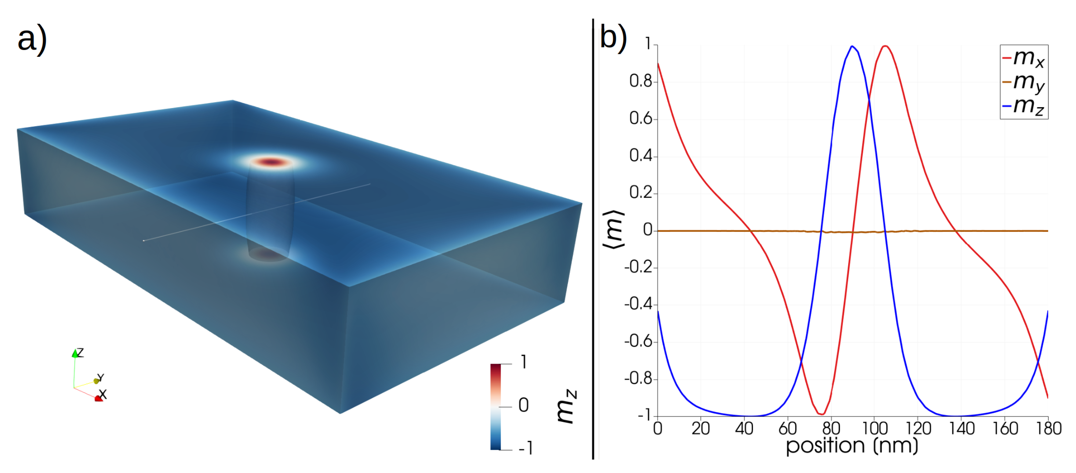
At sufficiently large field values, the platelet can also sustain individual skyrmions which are not arranged in the form of a lattice. Figure 2a shows an example of a magnetic structure containing a single skyrmion, located at the center of a 60 thick platelet in a 650 field. At this film thickness, the single-skyrmion state does not represent the minimum energy configuration. Nevertheless, the skyrmion is stable and possesses the usual properties of topological protection. In particular, the skyrmion could be manipulated and displaced, such as by means of spin-polarized electrical currents, as is done in racetrack-type devices. We will show later that it is possible to influence the position of such freely moving skyrmions by introducing geometric variations in the platelet, and thereby generate effective pinning sites for skyrmions. In order to obtain more information on the size and the profile of the skyrmion, we display the magnetization components along a line scan through the center, as shown in Figure 2b. The graphs show that the skyrmion is of Bloch type, with vanishing radial magnetization component along the central line. The diameter of the skyrmion core, defined as the distance between two diametrically opposed zero-crossings of the z-component of the magnetization, is almost exactly 30 . We found that the skyrmion diameter does not display noticeable variations if the film thickness changes, such as from 60 to 30 .
At elevated field values and larger film thicknesses, a quasi-homogeneous state is formed (not shown), where the magnetization is largely aligned along the external field direction. At fields below saturation, chiral bobber (ChB) [30,31] structures are also observed. These complex configurations of the magnetization can be considered as variants of skyrmions which do not traverse the entire thickness of the sample. Instead, they have a skyrmion-like structure only on one surface, which evolves into a quasi-saturated configuration on the opposite surface on a path along the film thickness. The apex of the ChB contains a Bloch point at which the magnetic structure changes in a discontinuous way. ChB structures have interesting micromagnetic properties, and have recently been discussed as magnetic structures that could be attractive in the context of spintronic devices [31], but they are not of primary interest for our study. We display an example of a ChB structure only for completeness in the upper right of Figure 1f, where it coexists alongside four ordinary skyrmions. The magnetic structures shown in Figure 1 were obtained by starting from a random initial configuration and by a subsequent energy minimization. For more details, see Section 4.
2.2. Phase Diagram of the Magnetization States
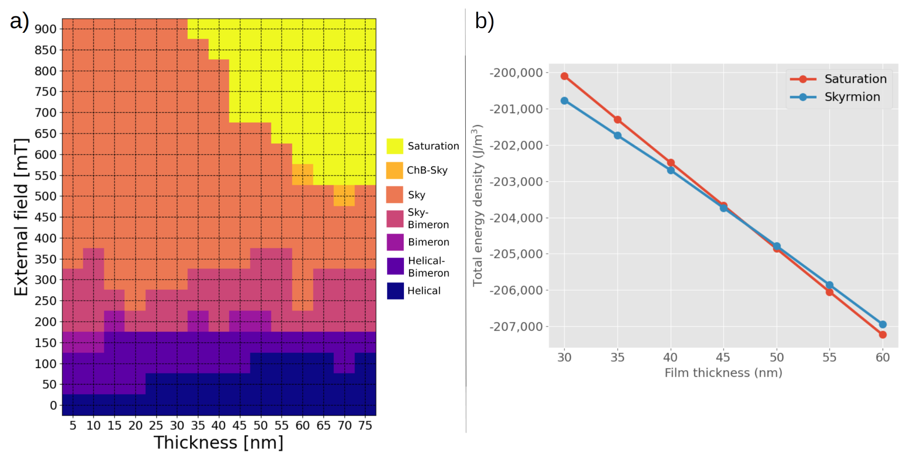
The various magnetic states described in the previous section are possible equilibrium configurations of the magnetization forming in the FeGe platelets at different values of the external field and the film thickness. It is important to note that these magnetic structures are not uniquely determined by the film thickness and the field strength. Because of this, in order to avoid possible misunderstandings, we did not specify the values of the thickness and the field strength at which the states shown in Figure 1 occur. In fact, several metastable states that can be significantly different from each other are often possible under identical conditions, depending only on the magnetic history of the sample or, in a numerical experiment, on the initial conditions of the simulation. While it is generally not possible to identify a unique magnetization state that develops in the thin-film element, micromagnetic simulations can be used to determine the type of magnetic structure that has the lowest energy. The results of these calculations are summarized in the phase diagram shown in Figure 3a.
Although the magnetic structure at a specific thickness and field value is generally not unique, the phase diagram helps identifying the most preferable structure as far as the total energy is concerned. While at lower field values (below about 400 ) the phase diagram is rather complex, evidencing a multitude of possible magnetic structures showing neither any clearly dominating state nor a significant thickness dependence, the situation becomes simpler at larger field strengths (above about 600 ). Two main states emerge in these ranges of larger field values—the skyrmion configuration and the quasi-saturated states. Moreover, these states are separated by a clearly defined boundary in the phase diagram, showing a distinct impact of the film thickness. Specifically, if a field of 650 is applied, the formation of skyrmion structures will be energetically favorable if the film thickness is below 50 , while a quasi-saturated state will be the lowest-energy configuration at larger thickness values, as shown in Figure 3b. This observation represents the fundamental of the concept of geometrically constrained skyrmions that we present in this study. The idea is the following. If the film thickness is locally modulated within a small dot-shaped region such that, at a given field, the skyrmion structure is favorable in that thinner part while in the rest of the sample, the thickness is large enough to favor a quasi-homogeneous state, these thickness modulations can be designed to capture skyrmions. As we will show, this patterning makes it possible to generate pinning sites for skyrmions and, to some extent, to achieve a geometric control of the skyrmion position within the thin-film element.
2.3. Geometrically Constrained Skyrmions
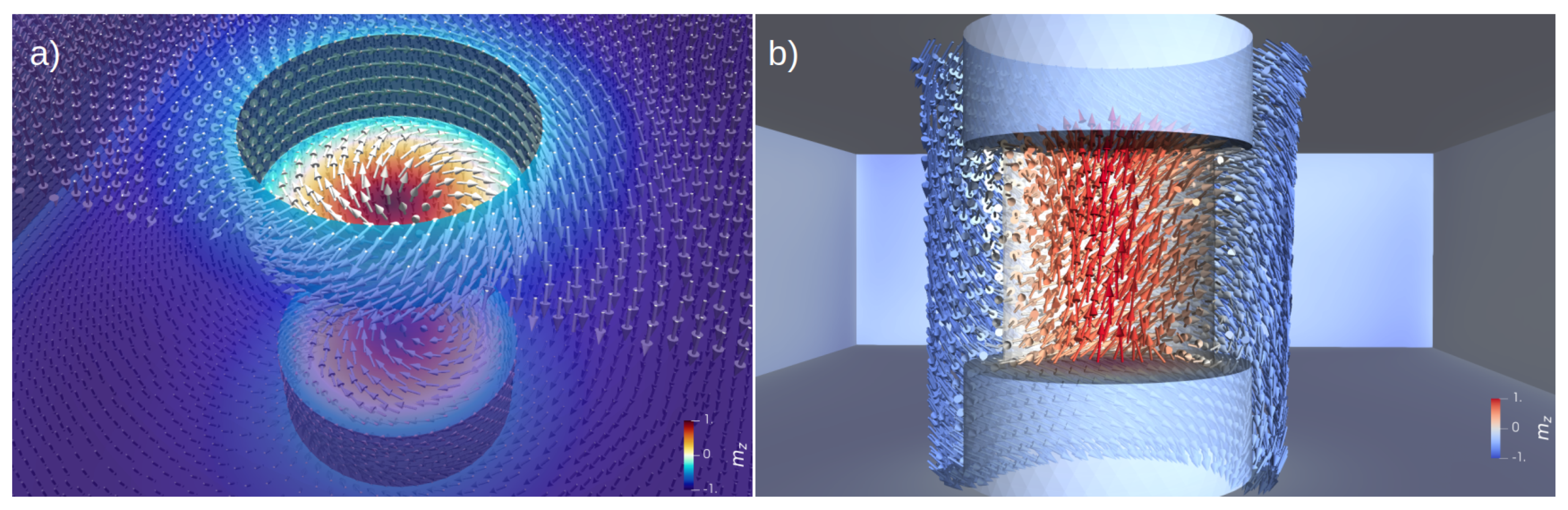
We now consider magnetic structures forming in an FeGe platelet of 60 thickness containing dot-like cylindrical cavities within which the thickness is locally reduced to 30 . The phase diagram displayed in Figure 3 suggests that, at external field values of about 650 , the insertion of these cavities results in a geometry with specific regions favoring the stability of skyrmion structures in a thin-film element which would otherwise favor a quasi-homogeneous magnetic configuration. This can lead to the formation, or the trapping, of skyrmions that are geometrically constrained to the regions in which the pockets have been introduced. Figure 4 shows such a geometrically constrained skyrmion in a 60 thick platelet. The skyrmion remains confined to the small region in which the thickness is reduced by 50 through two cylindrical pockets with a depth of 15 and radius of , inserted symmetrically on both the top and bottom surfaces. In order to accommodate a single skyrmion, the pocket radius is chosen to be slightly larger than the radius of the skyrmion core (15 ), obtained by a line-scan of the magnetization components of an isolated skyrmion, as shown in Figure 2.
The geometrically constrained skyrmion, shown in Figure 4, is stabilized by the geometry for two reasons. Firstly, as discussed before, in this field range the skyrmion state is generally favored because of the reduced film thickness. Secondly, the vortex-like magnetic configuration forming on the interior cylinder surfaces of the cavity helps in pinning the position of the skyrmion to the center of the pocket. This cylindrical flux-closure structure thereby provides boundary conditions, albeit not in a mathematical sense, which constrain the skyrmion to this dot-like geometry. By forming such a cylindrical vortex structure, the magnetization finds a nearly optimal way to adapt to competing micromagnetic interactions. It thereby satisfies both the tendency of the DMI to introduce chiral, swirling patterns, as well as the tendency imposed by the magnetostatic interaction to form flux-closure structures with the magnetization aligned along the surfaces. The simulations show that a symmetric insertion of these pockets on both the top and bottom surfaces is necessary to obtain the desired stability and localization of skyrmions. If the thickness variation is introduced only on one of the surfaces, the pinning of skyrmions appears to be much less effective. This result suggests that the previously mentioned swirling of the magnetization at the interior of the cylindrical pockets contributes significantly to the stabilization of the skyrmion position, and that sufficiently strong pinning can only be achieved if these swirling boundary conditions are imposed on both sides of the film.
If geometric modifications of the sample surface, as described above, can stabilize a skyrmion, the question arises whether this effect can be used to place skyrmions at specific positions where they might be generated or removed in a controlled way through external manipulation. This could be of interest, such as for device concepts in which skyrmions are utilized as binary units of information, in a context similar to that of dot-patterned magnetic media for high-density data storage [32]. In this case, the skyrmion pockets would take the role of the magnetic nanodots in bit-patterned media. While it is beyond the scope of this study to discuss the technical feasibility of such storage media or to explore the ability to write and delete individual skyrmion patterns into the pockets, we can show that, indeed, it is possible to stabilize skyrmions in various geometrically predefined locations that could be addressed individually.
Figure 5a–e shows several examples of simulations in which the position of skyrmions in a thin-film element can be predetermined by introducing several pockets of the type discussed before. As shown in Figure 5e, our simulations predict the possibility to stabilize six skyrmions at well-defined positions, placed on a regular grid, in our sub-micron FeGe platelet. Although the results shown in Figure 5 may suggest a nearly optimal geometric control of the skyrmion positions, it is important to note that the pockets discussed here merely provide preferential sites for skyrmions. The latter may or may not form or remain pinned at those sites. In particular, it is not sufficient to thin-out a part of the sample to ensure the appearance of geometrically constrained skyrmions. The purpose of such pockets could rather be to capture existing skyrmions and to fix them at well-defined positions, similar to the domain-wall pinning role that is played by notches in conventional racetrack-memory devices [20,33]. It should also be noted that the geometric trapping of skyrmions with such pockets does not always work, in particular when the pockets are too closely packed. As a rule of thumb, the material must observe a characteristic minimal distance between the skyrmions that is given by the material-dependent, long-range helical period , which in the case of FeGe, is about 70 (see Section 4).
If two skyrmions are constrained in adjacent pockets, the magnetization rotates smoothly by 360 along a line connecting the cores of these skyrmions. Such a continuous rotation of the magnetization direction involves the formation of a spin spiral that must be compatible with the properties of the material. In particular, two skyrmions cannot be constrained geometrically at distances that would be too small to accommodate spin spirals with a periodicity that is much smaller than . We emphasize that, in this context, only serves as an estimate for the minimal distance between skyrmions, and that inter-skyrmion distances may be larger than , in particular in the case of stronger external fields [34]. Beyond the simple analytic estimate of the minimal skyrmion spacing based on , detailed studies have established inter-skyrmion repulsion as a general effect [35,36,37], which ensures that a minimum distance between neighboring skyrmions is preserved. As an example of a dense array of constrained skyrmions approaching this limit, the nearest-neighbor spacing in the array (measured as the distance between the centers of the pockets) of constrained skyrmions shown in Figure 5a is 90 . This spacing is compatible with the analytically estimated minimum distance of 70 given by the material’s helical long-range period, . In this geometry, adding more pockets would reduce the minimal distance below this value, and thereby destabilize the pinning effect. We also found that skyrmions cannot be stabilized at positions too close to the lateral sample boundaries. This observation is consistent with the skyrmion-edge repulsion effect [8,35,37,38,39], which leads to an increase in energy as a skyrmion approaches the edges of a thin-film element. An example of such a failed attempt to stabilize skyrmions close to the lateral boundaries is shown in Figure 5f. In spite of these limitations, the ability to geometrically constrain skyrmions provides an attractive way to obtain control over the skyrmion position in thin-film elements, which could have important technological implications.
3. Discussion
By means of micromagnetic finite-element simulations, we have presented a possibility to control the position of magnetic skyrmions at predefined positions within a thin-film element by introducing cylindrical nano-pockets graved into the surface. Our concept for geometrically constraining skyrmions via such dot-like thickness variations is, in many ways, analogous to the idea of geometrically constrained domain walls [40] in cylindrical nanowires, or to studies in which indentations have been introduced in rectangular strips in order to capture head-to-head domain walls in racetrack-type memory devices [22]. In those cases, too, the desired effect of the geometric constraint is to define preferential sites for specific micromagnetic structures, such that the magnetic structures constrained at those artificial pinning sites require a certain activation energy in order to detach from them. The pockets described in this work could effectively play this role in the case of skyrmions driven along magnetic strips by means of spin-polarized electrical currents. Such geometric control of their position would allow for shifting skyrmions between well-defined points on the track. With the perspective of a possible implementation of this concept in skyrmion-based racetrack devices, future research could address the precise pinning strength that would result from those pockets and the current density that would be required to depin skyrmions captured in such pockets. If the skyrmion pinning effect resulting from pockets, as described in this study, should turn out to be too strong for application purposes, the pinning potential could be reduced in a gradual and straightforward way by modifying the geometric parameters of the pockets. For instance, a weaker pinning effect could be achieved by reducing the depth of the pockets, or by smoothing the edges of the cylinder, such as to yield rounded or cone-shaped pockets.
While racetrack-type skyrmion devices are probably the most straightforward application in which our idea to capture skyrmions at geometrically defined sites could be implemented, the concept of constrained skyrmions could also be useful for other purposes. As mentioned before, the trapping of skyrmions at dot-like sites could serve as a principle for skyrmion-based data storage devices, without necessarily involving any displacement or depinning processes. If skyrmions can be selectively generated and dissolved at such preferential sites, such as by means of the field of a magnetized nano-tip or through a localized spin-polarized current traversing the film thickness, the geometrically constrained skyrmions could represent units of information that could be written and erased. Perhaps such skyrmionic dot material could even be stacked in three dimensions for ultra high-density storage purposes. To address such possibilities, future research directions could explore ways to reversibly insert skyrmions in these geometrically defined regions. Another potentially interesting use of our concept concerns magnonic applications [19,41]. Since skyrmions can act as point-like scattering centers for spin waves, the ability to arrange them at regular lattice sites, as described in this study, could open up new perspectives, as this could result in a new type of magnonic metamaterial in the form of artificial magnon Bragg lattices consisting of skyrmions. Such artificial structures could be tailored to yield specific scattering and interference properties for spin waves that could not be obtained otherwise.
4. Materials and Methods
The material modelled in this study is FeGe. Due to its well-known helimagnetic properties, this B20-type, non-centrosymmetric material serves as a prototype for materials hosting chiral magnetic structures that develop due to the “bulk” DMI effect, as opposed to certain systems of ultra-thin magnetic films and substrates that can generate an “interfacial” DMI [1]. The micromagnetic parameters of FeGe are [18,42] , , and , where A is the ferromagnetic exchange constant, the saturation magnetization, and D the DMI constant. We neglect any magnetocrystalline anisotropy of the material, setting the uniaxial anisotropy to zero, . A characteristic length scale of this material is the long-range helical period [43]. This length scale describes the typical period length of magnetic spirals forming as a result of the competing interactions of the ferromagnetic exchange on one hand, and the DMI on the other. The ordering temperature of FeGe is [43]. Therefore, skyrmion devices based on this material are not expected to be operational at room temperature. Chiral structures in FeGe have been observed experimentally, such as at 100 [37], but recent studies have evidenced that in this material system, skyrmions can be stable also near room-temperature [10,44]. These developments suggest that, although thermal stability is a topic of central importance in skyrmion research [3], temperature limits do not represent a significant obstacle in the case of FeGe.
With the material parameters defined above, the total energy of the system is given by the sum of the Zeeman term, the ferromagnetic exchange, the DMI interaction, and the magnetostatic energy:
Here, V is the sample volume, is the externally applied magnetic field, is the vacuum permeability, is the reduced (normalized) magnetization, and u is the magnetostatic scalar potential. The magnetostatic (demagnetizing) field is the gradient field of the magnetostatic potential. We calculate the magnetostatic potential u, which accounts for the long-range dipolar interaction, by using the hybrid finite-element method/boundary element method (FEM/BEM) introduced by Fredkin and Koehler [45,46]. The dense matrix occurring in the boundary integral part of this formalism is represented using -type hierarchical matrices [47]. This data-sparse representation effectively overcomes size limitations arising from the boundary element method, as it yields a linear scaling of the computational resources required for the calculation of the magnetostatic term, which would otherwise grow quadratically with the number of degrees of freedom on the surface.
For each energy term, an effective field is defined as the variational derivative of the corresponding partial energy E,
Specifically, the effective field of the ferromagnetic exchange is
and the effective field of the DMI is
Together with the magnetostatic field and the external (Zeeman) field, these effective fields enter the Landau-Lifshitz-Gilbert (LLG) equation [48], which describes the evolution of the magnetization field in time,
where is the gyromagnetic ratio and is a phenomenological, dimensionless damping constant. We use the LLG equation to calculate equilibrium structures of the magnetization, by integrating in time until convergence is reached. In the numerical simulations, convergence is achieved when either the total energy ceases to change over a long period, or when the torque (magnitude of the right hand side of the LLG equation) drops below a user-defined threshold. The skyrmions stabilized in the pockets, as shown in Figure 5, result from a relaxation process starting from an out-of-plane saturated state of the film. As is common practice in micromagnetic simulations, we consider thermal effects only implicitly via the material parameters. Hence, temperature does not enter directly as a parameter in the simulations.
The geometry of the samples is designed with FreeCAD [49] and the discretization into linear tetrahedral elements is performed with Netgen [50]. The visualization of the FEM data was done with ParaView [51]. The finite-element cell size does not exceed , which is well below the exchange length , in order to avoid discretization errors. The finite element meshes in this study contain typically about one million finite elements. The micromagnetic simulations are done with our proprietary GPU-accelerated finite-element software [47].
The discretized representation of the vector field of the magnetization is given by a value of defined at each node (vertex) i of the finite-element mesh. The magnetostatic field, as well as the effective fields of the ferromagnetic exchange and the DMI, are calculated within each tetrahedral element. The element-based data of these fields are then mapped onto the nodes of the mesh, in order to calculate the effective field acting on the magnetization, and thus to calculate the evolution of the magnetization in time at each node according to the LLG equation. More details on the calculation of the converged magnetization states are given in Appendix A.
Author Contributions
Conceptualization, S.A.P.; methodology, R.H. and S.A.P.; software, R.H.; writing—original draft preparation, R.H. and S.A.P.; writing—review and editing, R.H. and S.A.P.; visualization, R.H. and S.A.P.; supervision, R.H.; project administration, R.H.; funding acquisition, R.H. All authors have read and agreed to the published version of the manuscript.
Funding
This work has benefited from support by the initiative of excellence IDEX-Unistra (ANR-10-IDEX-0002-02) through the French National Research Agency (ANR) as part of the “Investment for the Future” program.
Institutional Review Board Statement
Not applicable.
Informed Consent Statement
Not applicable.
Data Availability Statement
The simulation data are available from the authors upon reasonable request.
Acknowledgments
The authors acknowledge the High Performance Computing center of the University of Strasbourg for supporting this work by providing access to computing resources. Part of the computing resources were funded by the Equipex Equip@Meso project (Programme Investissements d’Avenir) and the CPER Alsacalcul/Big Data.
Conflicts of Interest
The authors declare no conflict of interest. The funders had no role in the design of the study; in the collection, analyses, or interpretation of data; in the writing of the manuscript, or in the decision to publish the results.
Abbreviations
The following abbreviations are used in this manuscript:
| DMI | Dzyaloshinksii-Moryia interaction |
| LLG | Landau-Lifshitz-Gilbert equation |
| FEM | Finite Element Method |
| BEM | Boundary Element Method |
| GPU | Graphical Processing Unit |
| 3D | three-dimensional |
| ChB | chiral bobber |
Appendix A. Energy Minimization
Because in this particular study we are not interested in the dynamic evolution of the magnetization but only in static, converged magnetic structures, the integration of the LLG equation in the code fulfils the practical role of guiding the system along a path of energy-minimization in an iterative way. Since the dynamics of the magnetization during the transition from the initial to the converged state is irrelevant for this work, we are free to choose a conveniently large damping parameter in order to accelerate the energy minimization. Furthermore, we remove the precession term by setting in Equation (5), thereby effectively using a a direct energy minimization scheme instead of following the path of the magnetization dynamics described by the LLG equation. The numerical integration is done with a Dormand-Prince algorithm [52], and the effective field values are refreshed several times during each time step. The choice of a large value of the damping allows us to use time steps of up to 1 , which is about ten times larger than the step size that we would usually employ in dynamic simulations with low damping. With these parameters, and owing to the GPU acceleration of our code, it takes only a short time (between several minutes and a few hours) to simulate the magnetic structures discussed in this work. To calculate the skyrmion states, we either start from a random configuration or saturate the magnetization along the positive z direction and subsequently let the system relax in the presence of an external magnetic field aligned along the negative z direction. The z axis is oriented parallel to the surface normal, as shown in Figure 1.
References
- Finocchio, G.; Büttner, F.; Tomasello, R.; Carpentieri, M.; Kläui, M. Magnetic skyrmions: From fundamental to applications. J. Phys. D Appl. Phys. 2016, 49, 423001. [Google Scholar] [CrossRef]
- Everschor-Sitte, K.; Masell, J.; Reeve, R.M.; Kläui, M. Perspective: Magnetic skyrmions—Overview of recent progress in an active research field. J. Appl. Phys. 2018, 124, 240901. [Google Scholar] [CrossRef] [Green Version]
- Back, C.; Cros, V.; Ebert, H.; Everschor-Sitte, K.; Fert, A.; Garst, M.; Ma, T.; Mankovsky, S.; Monchesky, T.L.; Mostovoy, M.; et al. The 2020 skyrmionics roadmap. J. Phys. D Appl. Phys. 2020, 53, 363001. [Google Scholar] [CrossRef]
- Muhlbauer, S.; Binz, B.; Jonietz, F.; Pfleiderer, C.; Rosch, A.; Neubauer, A.; Georgii, R.; Boni, P. Skyrmion Lattice in a Chiral Magnet. Science 2009, 323, 915–919. [Google Scholar] [CrossRef] [Green Version]
- Yu, X.; Onose, Y.; Kanazawa, N.; Park, J.; Han, J.; Matsui, Y.; Nagaosa, N.; Tokura, Y. Real-space observation of a two-dimensional skyrmion crystal. Nature 2010, 465, 901–904. [Google Scholar] [CrossRef] [PubMed]
- Oike, H.; Kikkawa, A.; Kanazawa, N.; Taguchi, Y.; Kawasaki, M.; Tokura, Y.; Kagawa, F. Interplay between topological and thermodynamic stability in a metastable magnetic skyrmion lattice. Nat. Phys. 2016, 12, 62–66. [Google Scholar] [CrossRef] [Green Version]
- Iwasaki, J.; Mochizuki, M.; Nagaosa, N. Universal current-velocity relation of skyrmion motion in chiral magnets. Nat. Commun. 2013, 4, 1463. [Google Scholar] [CrossRef]
- Iwasaki, J.; Mochizuki, M.; Nagaosa, N. Current-induced skyrmion dynamics in constricted geometries. Nat. Nanotechnol. 2013, 8, 742–747. [Google Scholar] [CrossRef] [Green Version]
- Xuan, S.; Liu, Y. Nonuniform gyrotropic oscillation of skyrmion in a nanodisk. AIP Adv. 2018, 8, 045312. [Google Scholar] [CrossRef] [Green Version]
- Yu, X.Z.; Kanazawa, N.; Onose, Y.; Kimoto, K.; Zhang, W.Z.; Ishiwata, S.; Matsui, Y.; Tokura, Y. Near room-temperature formation of a skyrmion crystal in thin-films of the helimagnet FeGe. Nat. Mater. 2011, 10, 106–109. [Google Scholar] [CrossRef]
- Boulle, O.; Vogel, J.; Yang, H.; Pizzini, S.; de Souza Chaves, D.; Locatelli, A.; Menteş, T.O.; Sala, A.; Buda-Prejbeanu, L.D.; Klein, O.; et al. Room-temperature chiral magnetic skyrmions in ultrathin magnetic nanostructures. Nat. Nanotechnol. 2016, 11, 449. [Google Scholar] [CrossRef] [PubMed] [Green Version]
- Heinze, S.; Von Bergmann, K.; Menzel, M.; Brede, J.; Kubetzka, A.; Wiesendanger, R.; Bihlmayer, G.; Blügel, S. Spontaneous atomic-scale magnetic skyrmion lattice in two dimensions. Nat. Phys. 2011, 7, 713–718. [Google Scholar] [CrossRef]
- Yu, X.; Kanazawa, N.; Zhang, W.; Nagai, T.; Hara, T.; Kimoto, K.; Matsui, Y.; Onose, Y.; Tokura, Y. Skyrmion flow near room temperature in an ultralow current density. Nat. Commun. 2012, 3, 988. [Google Scholar] [CrossRef] [PubMed] [Green Version]
- Fert, A.; Cros, V.; Sampaio, J. Skyrmions on the track. Nat. Nanotechnol. 2013, 8, 152–156. [Google Scholar] [CrossRef]
- Seki, S.; Yu, X.; Ishiwata, S.; Tokura, Y. Observation of skyrmions in a multiferroic material. Science 2012, 336, 198–201. [Google Scholar] [CrossRef] [Green Version]
- Rybakov, F.N.; Borisov, A.B.; Bogdanov, A.N. Three-dimensional skyrmion states in thin films of cubic helimagnets. Phys. Rev. B 2013, 87, 094424. [Google Scholar] [CrossRef] [Green Version]
- Rybakov, F.N.; Borisov, A.B.; Blügel, S.; Kiselev, N.S. New spiral state and skyrmion lattice in 3D model of chiral magnets. New J. Phys. 2016, 18, 045002. [Google Scholar] [CrossRef] [Green Version]
- Beg, M.; Carey, R.; Wang, W.; Cortés-Ortuño, D.; Vousden, M.; Bisotti, M.A.; Albert, M.; Chernyshenko, D.; Hovorka, O.; Stamps, R.L.; et al. Ground state search, hysteretic behaviour, and reversal mechanism of skyrmionic textures in confined helimagnetic nanostructures. Sci. Rep. 2015, 5, 17137. [Google Scholar] [CrossRef] [Green Version]
- Ma, F.; Zhou, Y.; Braun, H.B.; Lew, W.S. Skyrmion-Based Dynamic Magnonic Crystal. Nano Lett. 2015, 15, 4029–4036. [Google Scholar] [CrossRef]
- Parkin, S.S.P.; Hayashi, M.; Thomas, L. Magnetic Domain-Wall Racetrack Memory. Science 2008, 320, 190–194. [Google Scholar] [CrossRef] [PubMed]
- Bedau, D.; Kläui, M.; Rüdiger, U.; Vaz, C.A.F.; Bland, J.A.C.; Faini, G.; Vila, L.; Wernsdorfer, W. Angular dependence of the depinning field for head-to-head domain walls at constrictions. J. Appl. Phys. 2007, 101, 09F509. [Google Scholar] [CrossRef] [Green Version]
- Bogart, L.K.; Eastwood, D.S.; Atkinson, D. The effect of geometrical confinement and chirality on domain wall pinning behavior in planar nanowires. J. Appl. Phys. 2008, 104, 033904. [Google Scholar] [CrossRef] [Green Version]
- Garcia-Sanchez, F.; Kákay, A.; Hertel, R.; Asselin, P. Depinning of Transverse Domain Walls from Notches in Magnetostatically Coupled Nanostrips. Appl. Phys. Express 2011, 4, 033001. [Google Scholar] [CrossRef]
- Suess, D.; Vogler, C.; Bruckner, F.; Heistracher, P.; Slanovc, F.; Abert, C. Spin Torque Efficiency and Analytic Error Rate Estimates of Skyrmion Racetrack Memory. Sci. Rep. 2019, 9, 4827. [Google Scholar] [CrossRef]
- Liu, Y.H.; Li, Y.Q. A mechanism to pin skyrmions in chiral magnets. J. Phys. Condens. Matter 2013, 25, 076005. [Google Scholar] [CrossRef]
- Hanneken, C.; Kubetzka, A.; Bergmann, K.V.; Wiesendanger, R. Pinning and movement of individual nanoscale magnetic skyrmions via defects. New J. Phys. 2016, 18, 055009. [Google Scholar] [CrossRef] [Green Version]
- Müller, J.; Rosch, A. Capturing of a magnetic skyrmion with a hole. Phys. Rev. B 2015, 91, 054410. [Google Scholar] [CrossRef] [Green Version]
- Karube, K.; White, J.S.; Reynolds, N.; Gavilano, J.L.; Oike, H.; Kikkawa, A.; Kagawa, F.; Tokunaga, Y.; Rønnow, H.M.; Tokura, Y.; et al. Robust metastable skyrmions and their triangular–square lattice structural transition in a high-temperature chiral magnet. Nat. Mater. 2016, 15, 1237–1242. [Google Scholar] [CrossRef] [PubMed]
- Mandru, A.O.; Yıldırım, O.; Tomasello, R.; Heistracher, P.; Penedo, M.; Giordano, A.; Suess, D.; Finocchio, G.; Hug, H.J. Coexistence of distinct skyrmion phases observed in hybrid ferromagnetic/ferrimagnetic multilayers. Nat. Commun. 2020, 11, 6365. [Google Scholar] [CrossRef] [PubMed]
- Rybakov, F.N.; Borisov, A.B.; Blügel, S.; Kiselev, N.S. New Type of Stable Particlelike States in Chiral Magnets. Phys. Rev. Lett. 2015, 115, 117201. [Google Scholar] [CrossRef] [PubMed] [Green Version]
- Zheng, F.; Rybakov, F.N.; Borisov, A.B.; Song, D.; Wang, S.; Li, Z.A.; Du, H.; Kiselev, N.S.; Caron, J.; Kovács, A.; et al. Experimental observation of chiral magnetic bobbers in B20-type FeGe. Nat. Nanotechnol. 2018, 13, 451–455. [Google Scholar] [CrossRef] [PubMed]
- Ross, C. Patterned Magnetic Recording Media. Annu. Rev. Mater. Res. 2001, 31, 203–235. [Google Scholar] [CrossRef]
- Hayashi, M.; Thomas, L.; Rettner, C.; Moriya, R.; Jiang, X.; Parkin, S.S.P. Dependence of Current and Field Driven Depinning of Domain Walls on Their Structure and Chirality in Permalloy Nanowires. Phys. Rev. Lett. 2006, 97, 207205. [Google Scholar] [CrossRef]
- Wilson, M.N.; Butenko, A.B.; Bogdanov, A.N.; Monchesky, T.L. Chiral skyrmions in cubic helimagnet films: The role of uniaxial anisotropy. Phys. Rev. B 2014, 89, 094411. [Google Scholar] [CrossRef] [Green Version]
- Brearton, R.; van der Laan, G.; Hesjedal, T. Magnetic skyrmion interactions in the micromagnetic framework. Phys. Rev. B 2020, 101, 134422. [Google Scholar] [CrossRef] [Green Version]
- Lin, S.Z.; Reichhardt, C.; Batista, C.D.; Saxena, A. Particle model for skyrmions in metallic chiral magnets: Dynamics, pinning, and creep. Phys. Rev. B 2013, 87, 214419. [Google Scholar] [CrossRef] [Green Version]
- Zhang, X.; Zhao, G.P.; Fangohr, H.; Liu, J.P.; Xia, W.X.; Xia, J.; Morvan, F.J. Skyrmion-skyrmion and skyrmion-edge repulsions in skyrmion-based racetrack memory. Sci. Rep. 2015, 5, 7643. [Google Scholar] [CrossRef] [PubMed]
- Sampaio, J.; Cros, V.; Rohart, S.; Thiaville, A.; Fert, A. Nucleation, stability and current-induced motion of isolated magnetic skyrmions in nanostructures. Nat. Nanotechnol. 2013, 8, 839. [Google Scholar] [CrossRef]
- Duine, R. Skyrmions singled out. Nat. Nanotechnol. 2013, 8, 800–802. [Google Scholar] [CrossRef]
- Bruno, P. Geometrically Constrained Magnetic Wall. Phys. Rev. Lett. 1999, 83, 2425–2428. [Google Scholar] [CrossRef] [Green Version]
- Garst, M.; Waizner, J.; Grundler, D. Collective spin excitations of helices and magnetic skyrmions: Review and perspectives of magnonics in non-centrosymmetric magnets. J. Phys. D Appl. Phys. 2017, 50, 293002. [Google Scholar] [CrossRef]
- Cortés-Ortuño, D.I.; Beg, M.; Nehruji, V.; Breth, L.; Pepper, R.; Kluyver, T.; Downing, G.; Hesjedal, T.; Hatton, P.; Lancaster, T.; et al. Proposal for a micromagnetic standard problem for materials with Dzyaloshinskii-Moriya interaction. New J. Phys. 2018. [Google Scholar] [CrossRef]
- Lebech, B.; Bernhard, J.; Freltoft, T. Magnetic structures of cubic FeGe studied by small-angle neutron scattering. J. Phys. Condens. Matter 1989, 1, 6105–6122. [Google Scholar] [CrossRef]
- Zhao, X.; Jin, C.; Wang, C.; Du, H.; Zang, J.; Tian, M.; Che, R.; Zhang, Y. Direct imaging of magnetic field-driven transitions of skyrmion cluster states in FeGe nanodisks. Proc. Natl. Acad. Sci. USA 2016, 113, 4918–4923. [Google Scholar] [CrossRef] [Green Version]
- Fredkin, D.; Koehler, T. Hybrid method for computing demagnetizing fields. IEEE Trans. Magn. 1990, 26, 415–417. [Google Scholar] [CrossRef]
- Koehler, T.; Fredkin, D. Finite element methods for micromagnetics. IEEE Trans. Magn. 1992, 28, 1239–1244. [Google Scholar] [CrossRef]
- Hertel, R.; Christophersen, S.; Börm, S. Large-scale magnetostatic field calculation in finite element micromagnetics with H2-matrices. J. Magn. Magn. Mater. 2019, 477, 118–123. [Google Scholar] [CrossRef] [Green Version]
- Gilbert, T.L. A phenomenological theory of damping in ferromagnetic materials. IEEE Trans. Magn. 2004, 40, 3443–3449. [Google Scholar] [CrossRef]
- Riegel, J.; Mayer, W.; van Havre, Y. FreeCAD (0.18). Available online: https://www.freecadweb.org/ (accessed on 12 December 2020).
- Schöberl, J. NETGEN An advancing front 2D/3D-mesh generator based on abstract rules. Comput. Vis. Sci. 1997, 1, 41–52. [Google Scholar] [CrossRef]
- Ayachit, U. The ParaView Guide: A Parallel Visualization Application; Kitware: Clifton Park, NY, USA, 2015. [Google Scholar]
- Ahnert, K.; Mulansky, M. Odeint—Solving Ordinary Differential Equations in C++. AIP Conf. Proc. 2011, 1389, 1586–1589. [Google Scholar] [CrossRef] [Green Version]
Figure 1.
Non-trivial magnetization states forming in a rectangular FeGe platelet (310 × 180 ) of varying thickness (between 5 and 60 ) at different external field values. The color code describes the out-of-plane component of the normalized magnetization, and the isosurfaces indicate the regions where is equal to zero. Structures of this type appear at different film thicknesses as the external magnetic field is applied along the negative z direction and is varied between 0 and 900 . The arrangement of these configurations in the image corresponds, roughly, to the order in which the preferential configurations appear upon increasing the field strength.

Figure 2.
(a) A single magnetic skyrmion in a 60 thick platelet, stabilized by a 650 field, can form as a metastable state. The skyrmion is located precisely at the center of the thin-film element. The cylindrical shape in the middle is the isosurface, which represents the core region of the skyrmion. (b) The normalized magnetization components along a central cutline—oriented parallel to the y direction and shown as a grey line in panel (a)—display the profile of the skyrmion. From the distance between two consecutive zero values of , we obtain the skyrmion core diameter to be 30 . The Bloch character of the skyrmion is evidenced by the antisymmetric shape of the x (azimuthal) component and the vanishing y (radial) component of the magnetization.

Figure 3.
(a) Phase diagram displaying the lowest-energy magnetic configuration in the FeGe platelet as a function of the film thickness and the external field strength. At high fields and large film thickness, the quasi-saturated state is the ground state. By lowering the film thickness, the formation of skyrmion structures tends to become energetically favorable. (b) Energy density as a function of the film thickness in the case of the skyrmion state (blue line) and the quasi-saturated state (red line) in an external field of 650 .

Figure 4.
(a) A skyrmion is formed at the base of the cylindrical pocket. At the inner cylinder surface of the cavities, the magnetization circulates on closed loops, thereby facilitating the formation of the skyrmion in the center. The semitransparent representation of the surfaces shows the formation of the skyrmion in both pockets, on the top and bottom surfaces. The magnetic structure is displayed by arrows on the sample surfaces. Some of the arrows have been removed in order to improve the visibility of the structure. (b) View on the simulated skyrmion structure from inside the film. The skyrmion core connects the bases of the cylindrical pockets in the positive z direction, while the surrounding volume is magnetized in the negative z direction. The core of the skyrmion is delimited by a cylindrical isosurface , shown here as a weak, transparent contrast in order to preserve the view on the central magnetic structure. Only a small subset of the calculated local magnetization vectors is displayed.

Figure 5.
Geometrically constrained skyrmions in FeGe platelets. By introducing circular pockets at specific positions, skyrmions can be artificially stabilized at positions that they would otherwise not attain. Panels (a–e) show examples in which each pocket contains a skyrmion. The geometric control, however, is not unlimited. Attempts to pack skyrmions too closely or to place them too close to the sample boundary can fail. This is shown in panel (f), where skyrmions are stabilized only in the three central pockets, while the two outermost pockets remain empty.

Publisher’s Note: MDPI stays neutral with regard to jurisdictional claims in published maps and institutional affiliations. |
© 2021 by the authors. Licensee MDPI, Basel, Switzerland. This article is an open access article distributed under the terms and conditions of the Creative Commons Attribution (CC BY) license (http://creativecommons.org/licenses/by/4.0/).
Share and Cite
MDPI and ACS Style
Pathak, S.A.; Hertel, R. Geometrically Constrained Skyrmions. Magnetochemistry 2021, 7, 26. https://0-doi-org.brum.beds.ac.uk/10.3390/magnetochemistry7020026
AMA Style
Pathak SA, Hertel R. Geometrically Constrained Skyrmions. Magnetochemistry. 2021; 7(2):26. https://0-doi-org.brum.beds.ac.uk/10.3390/magnetochemistry7020026
Chicago/Turabian StylePathak, Swapneel Amit, and Riccardo Hertel. 2021. "Geometrically Constrained Skyrmions" Magnetochemistry 7, no. 2: 26. https://0-doi-org.brum.beds.ac.uk/10.3390/magnetochemistry7020026
Note that from the first issue of 2016, this journal uses article numbers instead of page numbers. See further details here.