Article

Numerical Optimization of a Single Bunch of NiTi Wires to Be Placed in an Elastocaloric Experimental Device: Preliminary Results

Department of Industrial Engineering, University of Naples Federico II, Pl.e Tecchio 80, 80125 Naples, Italy
*
Author to whom correspondence should be addressed.
Submission received: 20 April 2021 / Revised: 11 May 2021 / Accepted: 12 May 2021 / Published: 15 May 2021
(This article belongs to the Special Issue Magnetocaloric and Caloric Materials for Solid-State Cooling)

Abstract

:
Italy has not yet presented to the scientific community any elastocaloric prototype suitable for refrigeration/air conditioning. The SUSSTAINEBLE project was born from the idea to build a demonstrative elastocaloric prototype for environmental conditioning. The prototype is planned to be rotary and composed by a few bunches of elastocaloric wires crossed by air as heat transfer fluid. Many are the parameters to be investigated before the realization of the device. A numerical practical tool would help to easily optimize the prototype. In this paper a two-dimensional tool of a single bunch of elastocaloric wires based on finite-element method is introduced; it can reproduce step by step the velocity and the pressure field of fluid to predict more accurately the solid-to-fluid heat exchange. The results of a test campaign mostly focused on the optimization of the frequency of the cycle, fluid velocity and the distance between the elastocaloric wires are presented. The results reveal that: (i) 0.12 Hz as frequency; (ii) 7 m s−1 as velocity; (iii) 1.0 mm as optimal wire distance, would better satisfy the trade-off existing in the maximization of temperature span and cooling power per mass unit: 23.7 K and 311.97 W kg−1 are the values achieved, respectively.

1. Introduction

1.1. Generalities

Nowadays, refrigeration and environmental conditioning are responsible for about 20% of the world’s energy consumption and the technology most accountable for this figure is Vapor Compression (VC) since it still is the benchmark technology in this field. The refrigerants employed in vapor compression have moved from CFCs and HCFCs, with Ozone Depletion Potential (ODP), to HFCs, greenhouse gases with a high Global Warming Potential (GWP). The Montreal [1] and Kyoto [2] Protocols, the subsequent amendments [3] and the consequent international and national laws and regulations deriving from them [4], have established very strict objectives aimed at a progressive reduction in greenhouse gases and in particular the gradual banning of HFCs [5,6,7,8,9,10], precisely because of their significant contribution to the greenhouse effect on our planet [11,12,13,14,15,16].
Therefore, never as in this historic moment has it been so necessary to find eco-compatible refrigeration techniques that constitute a valid alternative to vapor compression refrigeration systems; so the scientific community has been called upon to research for finding new solutions, using renewable energy sources [17,18,19,20,21] or developing completely new-concept technologies (Not-In-Kind) for cooling and air conditioning [22,23,24]. Among them is the class of solid-state technologies based on caloric effects [25] which is currently considered a promising alternative to vapor compression [26,27] as it is characterized by the use of materials that have not a direct greenhouse effect (GWP = 0) [28]. It has also been theoretically estimated that solid-state chillers could have an energy efficiency 50–60% higher than that of vapor compression [29].
The common denominator of solid-state heat refrigeration technologies is the caloric effect, a physical phenomenon manifesting in some solid-state materials where, consequently to an adiabatic variation of the intensity of an external field when applied, a temperature variation, called adiabatic temperature jump due to the caloric effect (ΔTad), occurs. If the intensity of the field follows an augmentation, an increase in temperature will be observed in the caloric material; conversely, if the intensity of the field is reduced, a reduction in temperature will be observed. The nature of the field applied to the material particularizes the caloric effect: the effect is called magnetocaloric if the field is magnetic [30]; electrocaloric if the field is electric [31]; elastocaloric if the field is a mechanical-structural stress [32], such as traction or compression; barocaloric if the field is a hydrostatic pressure [29]. Therefore, four solid-state refrigeration technologies derive from these effects (magnetocaloric, electro-caloric, elastocaloric and barocaloric) which globally constitute the class of solid-state refrigeration technologies based on caloric effects.
Magnetocaloric refrigeration is the most consolidated solid-state technology, as it was the first to attract the interest of the scientific community for the development of cooling applications in the field of room temperatures, about 25–30 years ago [33,34,35,36,37,38,39,40,41]. The magnetocaloric material that generally constitutes the regenerators is Gadolinium (Gd), a metal belonging to the class of rare earths, or its binary or tertiary alloys. To date, about 100 magnetocaloric prototypes have been developed, but still, few are close to being commercialized [42]. The major limitations are related to the energy performance characterized mostly by low values of the Coefficients Of Performance (COPs), low cooling capacities and low temperature jumps allowed. Anyway, all the theoretical and numerical analysis carried out so far gives very encouraging results, demonstrating the possibility of large energy savings (from 30% to 60%) compared to traditional technologies.
In recent times (in the last decade), there has been a progressive interest toward caloric refrigeration technologies, in particular toward the elastocaloric one. In 2014, Goetzler et al. [43] published a technical report on the “Energy Savings Potential and Opportunities for Non-Vapor-Compression HVAC Technologies” where they asserted that the real alternative breakthrough Non-Vapor-Compression technology is the elastocaloric, because of the colossal temperature change induced by the deformation of a Shape-Memory Alloy (SMA) by means of mechanical stress, i.e., the elastoCaloric Effect (eCE). In 2016 the European Commission [44] also identified the elastocaloric as the most hopeful substitute of vapor compression in the future.
Elastocaloric effect manifests in SMAs; specifically, this phenomenon is solidly correlated to the superelasticity and to the latent heat that the SMA rejects/absorbs during martensitic phase transformation (depending on if the SMA is loaded or unloaded). Austenite and Martensite are the structural phases in which the SMA could be, depending on the stress applied. The operation of stress increasing during the process of adiabatic loading, applied to an elastocaloric material that initially is of austenite status, generates an Austenitic-Martensitic (A-M) phase transformation. To these forward and reverse transformations, two exclusive properties of the elastocaloric materials are intrinsically related: shape-memory effect and superelasticity. The former is the property where a mechanically stressed elastocaloric material can keep in mind the shape it had before being loaded and be able to go back once the stress is removed and heat is released. The latter, i.e., the property of superelasticity, allows the SMA to be subjected to very large strains (up to 8.5%) and release the transformation heat [45]. Anyway, generally, the stress hysteresis phenomenon is associated with the Austenitic-Martensitic phase transition, specifically the A-M transition happens under a greater stress than the forward M-A transition.

1.2. State of the Art of the Elastocaloric Technology

Research on elastocaloric cooling and HVAC can be divided into three areas:
(a)
the research of promising elastocaloric materials provided with giant temperature changes at room temperature and sufficiently long fatigue life;
(b)
the realization of novel and competitive experimental devices;
(c)
the development of smart and versatile models to operate in parallel with the experimental field to the purpose of optimizing the performances.
(a) The elastocaloric benchmark material is the Nickel-Titanium (NiTi) binary alloy, whose elastocaloric properties were open to the scientific community in 1963 [46]. It is the most investigated shape memory alloy in the panorama of elastocaloric applications [47] because of its remarkable adiabatic temperature change (ΔTad) at room temperature due to eCE. Cui et al. conducted Ni-Ti wires showing a ΔTad of 25.5 K during loading and 17 K during unloading [48]. They can be classified according to the following categories: (i) SMA-based (Ni-Ti-based, Cu-based and Fe-based), (ii) Shape-Memory Polymer-based (SMP).
Next to the binary Ni-Ti, ternary or quaternary Ni-Ti alloys can improve the performance of the SMAs for different applications. With respect to the binary version, copper or vanadium addition to Ni-Ti alloys has the purpose to minimize the stress hysteresis and to enhance fatigue life [47]. Other popular SMA are the Cu-based as Cu-Zn and Cu-Sn, even if the ternary alloys (Cu-Zn-Al, Cu-Al-Ni) and others are more interesting, since they offer increased mechanical and thermal properties; i.e., the presence of Aluminum ensures an enhancement of the heat transfer coefficients [49,50]. Cu-Zn-Al is the most promising among the Cu-based alloys because of the highest latent heat shown, i.e., measured ΔTad up to 15 K (under the complete austenite/martensite transformation); on the contrary, the small fatigue life strongly limits the possibility of being employed for commercial applications. Fe-based SMAs are not so promising as the former two classes because they show much smaller latent heat on equal conditions, i.e., under the complete austenite/martensite transformation, (up to 5 K), even if a more reduced hysteresis is registered [51].
The class of soft materials with elastocaloric properties called Shape Memory Polymers, i.e., SMP, like rubber or polymers, compared with Ni-Ti alloys, is characterized by smaller tensile stress and costs, greater cooling capacity and fatigue life but larger volume variation; moreover the fatigue cracks can be repaired at high temperature, which constitutes a remarkable potential for elastocaloric cooling, since this allows the extension of the lifespan of these materials. In the class of Shape Memory Polymers there are the PVDF-based materials for which Patel et al. detected [52] 1.8 K as adiabatic temperature change under 15 MPa at 298 K, whereas P(VDF-TrFE-CTFE) exhibited 6 K under 200 MPa at 300 K. Others worthy of investigation, still belonging to the class of Shape Memory Polymers, are the so-called elastomers materials that, because of the alignment of polymer chains, can always manifest the elastocaloric effect. Among them, Natural Rubber, which is totally environmentally friendly, has shown 12 K as ΔTad under very small tensile stress applied (2 MPa) [53]. The real problem in employing such an elastomer in elastocaloric cooling application is the limited heat transfer capacity and the great strains (around 600%) needed to make the eCE manifesting, which make it not so practical to act in a device [54].
(b) To date, the elastocaloric prototypes developed so far in the world do not exceed ten units and are still far from prospects of use for residential or commercial cooling applications [42,47]. As maximal subclassification, the concepts for cooling or heat pumping by means of the elastocaloric technology can be implemented based disjunctively on: conductive heat transfer though the placement of chains of solid elements (eCE material and thermal diodes); convective heat exchange establishing itself between the eCE refrigerant and a Heat Transfer Fluid (HTF), in an Active elastocaloric Regenerator (AeR). Moreover, most of the prototypes are based on a linear mechanism for applying/removing stress, which is generally obtainable with the aid of a linear driver. This stress can be applied by means of a traction or compression operation.
The pioneers of elastocaloric device developing were Cui et al. [48] in 2012 when they introduced, during the ARPA-E Energy Innovation Summit Technology Showcase, the very first elastocaloric proof-of-concept for cooling, mounting NiTi wires (with 0.5 mm diameter) placed between two rings (the upper one is inclined). The rotation of the rings and the convective heat exchange with air (the Heat Transfer Fluid) ensures the exploitation of the AeR cooling cycle. The device achieved 17 K as maximum adiabatic temperature change (under 8.5% strain applied for stretching). The main problem of this device was the low lifetime of the refrigerant wires with a high percentage of cracking.
All the elastocaloric prototypes realized up until the end of 2018 were reviewed and accurately classified by Greco et al. [42]: they recognized that, next to the pioneer device mentioned above, three more devices had been presented to the scientific community, all based on linear mechanism and mounting Ni-Ti alloys in different shapes [55,56,57]. Subsequently, in late 2018, a German group from Saarland University introduced [58,59] a new rotary elastocaloric prototype mounting wires of Ni45Ti47.25Cu5V2.75 whose fatigue life is longer than the binary NiTi alloys and exhibiting a ΔTad of 28 K if loaded with a strain rate of 0.05 s−1 up to a maximum strain of 8.5%. Preliminary results on the device guaranteed 25 K as temperature span, 8.4 as COP and 250 as cooling power with a total mass of 50 g of elastocaloric material.
Another prototype was presented in 2019 by Snodgrass and Erickson [60]: the device has microscale solid-to-solid heat exchange based where a single Ni-Ti wire is cyclically loaded by stretching. The highest temperature span achieved is 28.3 K, which currently is also the largest value published in literature for an elastocaloric device. Anyway, the dimensions and the amount of Ni-Ti mounted made this prototype only a demonstrator, very far from commercialization.
Apart the one of Kirsch et al. [59], all the elastocaloric prototypes developed to date use NiTi as an elastocaloric material. In all the prototypes introduced in literature, the maximum percentage strain applied to the material is 9%; this is because the greater the induced stress, the shorter the life-time of the material used before it cracks. The study of the life-time and the fatigue life of the elastocaloric material used as a refrigerant is a fundamental aspect for the development of competitive devices, and for this reason the development of new elastocaloric materials is a very important and current topic in the scientific community of caloric refrigeration.
(c) Since as underlined above, one of the basic requirements is to find the most appropriate elastocaloric refrigerant providing a remarkable elastocaloric effect and a fatigue life able to guarantee a huge number of cycles before the manifesting of cracks. Additionally, the shape and the dimensions of the elastocaloric refrigerants mounted in a prototype, as well as the operating conditions (cycle frequency, speed of the HTF...) must be optimized. These aims could be achieved by the numerical modelling: the realization of a model able to predict the thermal and the energy performances of a device could constitute a guide tool to make the prototype work under the best conditions. Many are the models developed and published in open literature with the aim of perpetuating this purpose. Most of them are one-dimensional.
Tušek et al. [61] evaluated the performances of their elastocaloric cooling device [57] based on a 1-D numerical model, originally developed for simulating the performances of an Active Magnetocaloric Regenerative (AMR) device. The mathematical model of the tool is governed by the heat transfer model in a porous structure where the elastocaloric effect has been taken into account considering a simplified stress-strain relation. A comparison between the energy performances associated with the employment of parallel plates of the elastocaloric Ni-Ti and Cu-Zn-Al with respect to the Gadolinium in a magnetic refrigerator active regenerator has been carried out while the cycle frequency and the fluid flow rate were varied. A specific cooling power of up to 7 kW kg−1 and 4.3 kW kg−1 were detected with Ni-Ti and Cu-Zn-Al alloys, respectively; it was very high with respect to the 0.35 kW kg−1 ensured by the Gd in an AMR. The research group of Qian et al. has been very active in developing more and more accurate elastocaloric models [62,63,64]. The concept is one-dimensional and the model has been developed and upgraded in Matlab Simulink through the finite difference method. The model, which records the phase transformations kinetics through the evaluation of latent heat deriving by the compression of Ni-Ti elements, was developed to operate parallelly to the experimental device [56]. They asserted that there is a maximum deviation between numerical and experimental results and the tool is, to date, employed to improve the performances of their device. Luo et al. [65] introduced a systematic approach for optimal designing of an integrated elastocaloric heat pump system. The system, mounting Ni-Ti tubes, was targeted for a unit with 1.2 kW of cooling capacity. They detected that the loading/unloading time, as well as the heat exchange time periods, have strong incidence of temperature span and COP. The best result found is 2.7 as COP of a 1.2 kW elastocaloric heat pump operating with 35 °C as outdoor temperature and 23.9 °C and 60% as, respectively, indoor air and relative humidity.
Welsch et al. developed an efficient simulation tool [66] for reproducing the behavior of the rotary device developed by the group of Saarland University, to the final purpose of finding the optimized parameters guaranteeing the maximization of both thermal and energy performances. The model was presented during the Thermag 2018 Conference and validated with experimental results but, even if authors declared that further studies would have come soon to present the results of the optimization, currently they have not presented them yet to scientific community. The same group records another interesting work [67] in which, to the best of our knowledge, the most accurate model was presented where the behavior of superelastic elastocaloric materials in the thermo-mechanically coupled transformation, also recording the non-local effects, is modelled. The model is 1D and it is implemented through the finite element method. The model has been tested for the superelastic Ti55.2Ni29.3Cu12.7Co2.8 and it is able to predict the cooling performances of the material.

1.3. Research Gap and Aim of the Investigation

Although the elastocaloric refrigeration is very promising, the related state of the art proves its status of initial-state technology, little more than embryonic. Many efforts are still to be made in materials to identify an elastocaloric material presenting sufficient long-life and high-latent heat at the same time. The number of prototypes is exiguous and far are the perspectives of a commercialization in the near future.
Italy has not yet presented to the scientific community any elastocaloric prototypes suitable for refrigeration/air conditioning. The SUSSTAINEBLE project was born from this idea with the challenge, taken by the University of Naples Federico II, to build a demonstrative prototype of an elastocaloric system with application to environmental conditioning. The prototype is planned to be rotary and composed of a number of bunches of elastocaloric wires crossed by air as heat transfer fluid. Many are the parameters to be investigated before the device can be realized:
  • the number of the wires and the total number of bunches mounted, as well as the total mass of the elastocaloric refrigerant;
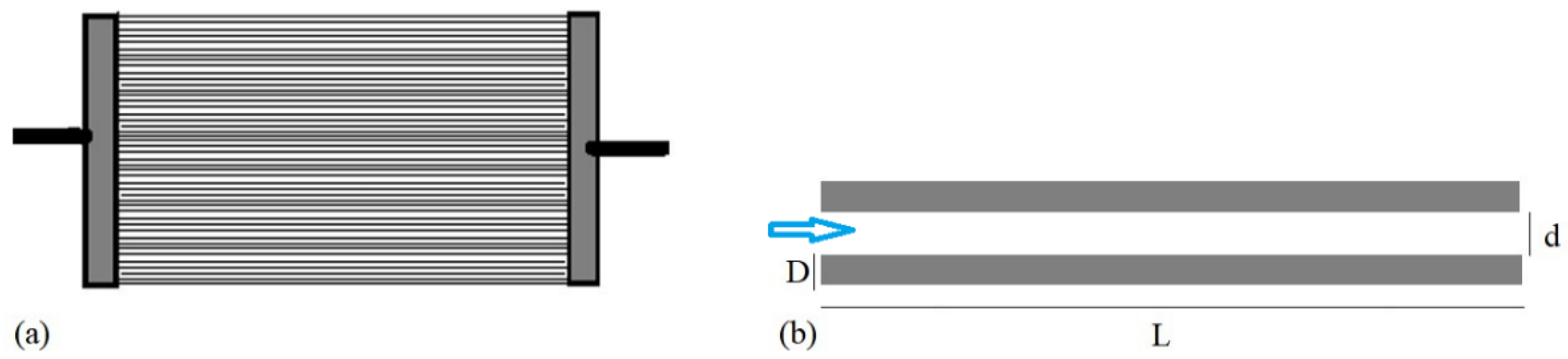
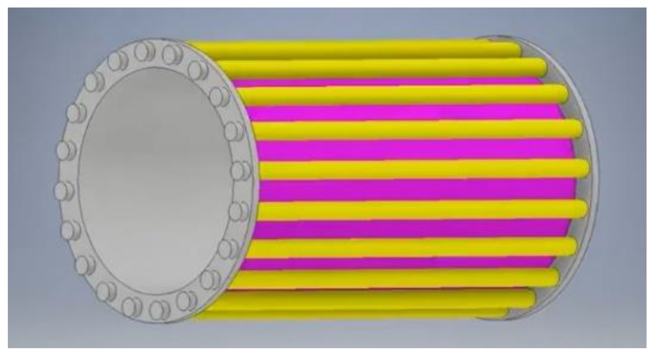
  • the dimensional parameters of the bunch as well as the ones of each wire: the diameter, the length, the distance between two of them;
  • the working parameters like air velocity and flow rate, the frequency of the elastocaloric cycle;
  • the composition of the elastocaloric material and correlatedly the stress applied to the wires.
Many are the variables involved, so, in order to design a device that would present an optimized design and that could employ the best elastocaloric material, the help of a numerical practical tool that could predict the behavior of the device is necessary.
In this paper we are going to introduce a two-dimensional tool of a single bunch of elastocaloric wires based on finite-element method. The novelties introduced by the model with respect to the others present in literature are:
  • the design is two dimensional whereas all the other models developed to support the projecting of an elastocaloric experimental prototype are one-dimensional.
  • the model can reproduce step by step the velocity and the pressure field of the fluid, in order to predict more accurately the solid-to-fluid heat exchange with respect to the literature tools where the heat exchange was estimated only by a fixed convective heat transfer coefficient.
We have planned an exhaustive and extensive test campaign and in this paper we are going to introduce the preliminary evaluation mostly focused on the optimization of some crucial parameters: the frequency of the cycle, fluid velocity, the diameter and the distance between the elastocaloric wires.

2. The Optimization of a Single Bunch of NiTi Wires

The element to be optimized is a single bunch of NiTi wires representing the active element of the first Italian elastocaloric prototype. The project foresees the presence of a certain number of elements arranged circularly, therefore the first step is to focus on one of them with the purpose of optimizing geometrical parameters and operative conditions and to identify the most suitable elastocaloric refrigerant. Specifically, in the present paper attention is devoted to maximizing the heat exchange between heat transfer fluid and SMA, by the choice of the most suitable operating frequency and fluid velocity range.

2.1. Materials

In this primary investigation, to operate with a reference elastocaloric material we opted for the benchmark Ni50.4Ti49.6. The Austenite finish temperature Af is 20 °C in order to guarantee the achievement of pseudoelastic behavior at room temperature. For this material, the maximum latent heat of the complete Austenite-Martensite transformation is 20 J g−1 which corresponds to a maximum adiabatic temperature change of 40 K [68]. Anyway, to ensure a long fatigue-life of the alloy, the SMA was considered to be subjected to a moderate strain rate of 0.25 s−1 (6%) that corresponds to a time period of around 200 ms for each loading and unloading process.
The heat transfer fluid is air since the prototype is designed for an air conditioning application; moreover, the air flowing in a rotative configuration would result in being easier to be realized. The air velocity and the fluid flow rate are parameters to be optimized.

2.2. Geometry

The SMA element we are going to characterize is a single bunch of NiTi wires parallelly placed, as shown in Figure 1a. Figure 1b, a zoom on two SMA wires, reveals that D and L are, respectively, the diameter and the length of each wire, whereas d is the distance between two wires that is a variable parameter object of the investigation. The heat transfer fluid (air) flows longitudinally, as the light-blue arrow indicates, with a velocity whose value is the object of the investigation.
The single bunch of NiTi, shown in Figure 1a, will be one of the elements that will constitute the active regenerator of the first Italian elastocaloric prototype. The latter will be based on a rotation mechanism in order to be in continuous operation. A schematic of the experimental device is shown in Figure 2, and it is based on the mechanical concept of two co-rotating disks with multiple bunches of elastocaloric elements (in yellow) placed around the circumference. The synchronous rotation of the two disks allows the elastocaloric elements to experience, at the same time, different phases of the AeR (Active elastocaloric Regenerative) cycle.

2.3. The Active Elastocaloric Regenerative Cycle

Each bunch of the prototype, i.e., the one described in the previous section, has the role of active elastocaloric regenerator and it experiments cyclically the four steps of the Active elastocaloric Regenerative cycle. Generally, the regenerator (made of elastocaloric SMA) is located between a Cold and a Hot Heat Exchanger (CHEX and HHEX), respectively, coupled with the cold and the hot environments. The four steps are:
(1)
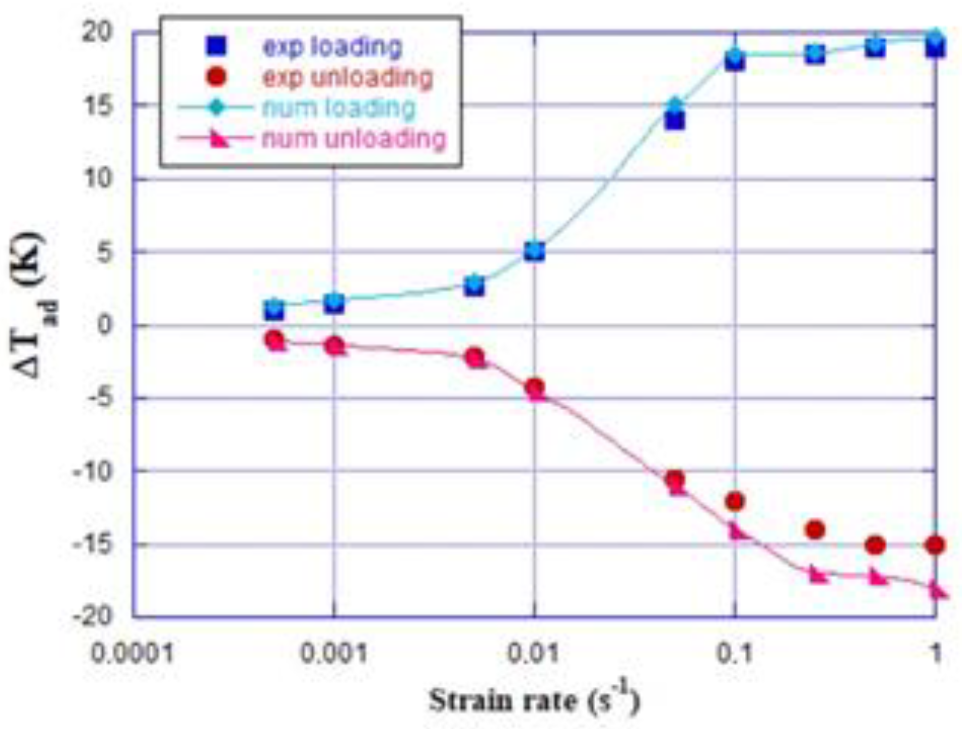
adiabatic loading, where the stress σ is applied to load the SMA, the A-M transformation occurs and the elastocaloric effect derives in a temperature increment in the SMA, equal to ΔTad (T, σ);
(2)
the SMA is cooled down since it is crossed by the HTF flowing from cold to hot heat exchanger, that absorbs heat from the SMA and releases it once it reaches the HHEX;
(3)
the SMA is furtherly cooled down because of the temperature decrease associated with M-A transformation, due to the stress removal in the unloading process;
(4)
the HTF cools down since it crosses the SMA from hot to cold side and subtract heat once it reaches the CHEX, so to realize the useful effect of the cycle, to which the cooling power is associated.

2.4. The Mathematical Model

The mathematical model that governs the above introduced system has been formulated according to the following assumptions:
-
the time required for the austenite-martensite and the reverse M-A transformations to take place is negligible comparing it with the convective heat transfer time;
-
the loading/unloading processes occur though uniaxially stretching operations;
-
the walls of the regenerators are thermally insulated with respect to the coating;
-
AM and MA phase transformations occur uniformly in the elastocaloric material.
Considering that:
  • the model is two-dimensional;
  • the velocity field of the fluid is solved and represented in the whole domain;
  • the temperature fields of the fluid and the solid, due to the convective heat exchange, follows the Navier-Stokes equations;
  • the elastocaloric effect is evaluated through the estimation of the latent heat and the work needed for loading/unloading following the Austenite-Martensite or Martensite-Austenite transformations;
The global system of the equations governing the tool is:
{ u x + v y = 0 u t + u u x + v u y = 1 ρ f p x + υ f ( 2 u x 2 + 2 u y 2 ) v t + u v x + v v y = 1 ρ f p y + υ f ( 2 v x 2 + 2 v y 2 ) ρ f c f T f t + ρ f c f ( u T f x + v T f y ) = k f ( 2 T f x 2 + 2 T f y 2 ) ρ S M A c S M A T S M A t = k S M A ( 2 T S M A x 2 + 2 T S M A y 2 ) + G
where G is the elastocaloric term that depends both on the latent heat and the loading/unloading work:
G = ρ S M A ( Δ H + w ) ξ ˙ M
According to many experimental studies, including the one of Ossmer et al. [68], on the elastocaloric effect in shape-memory alloys, the amount of latent heat associated to the forward and reverse austenite-martensite transformations is different, as well as a different value which assumes the work required for loading/unloading. According to Tusek et al. [69] the network:
w n e t = w l o a d w u n l o a d
represents the area enclosed by the entropy temperature hysteresis loop, if the cycle of loading/unloading steps is adiabatic.
The volume fraction of the martensitic phase ξ ˙ M can rigorously estimated through solving the differential Equation (4):
ξ ˙ M = ξ M ψ M A ( T S M A , σ ) ξ A ψ A M ( T S M A , σ )
where:
ξ M + ξ A = 1
Since the time required for the A-M M-A transformations to take place is negligible, the term ξ ˙ M only converts itself in +1 or −1, i.e., G changes its sign during the loading/unloading processes. Moreover, the time-duration of the loading/unloading process is so short that the convective heat exchanges in these steps are negligible.
On the other side, during the convective heat transfer processes the stress applied is not varying, thus ξ ˙ M = 0 and in the global system (Equation (1)) the elastocaloric term G is zero.
The model is based on Finite Element Method and the four processes are repeated cyclically; the number of the times needed to reach steady-state, as well as the meeting of the cyclicality criterion in every coordinate of the geometry is:
δ = m a x { T ( x , y , 0 + n θ ) T ( x , y , 4 τ + n θ ) } < ε ¯

2.5. Experimental Validation

The numerical investigation presented in this paper has been performed through a FEM (Finite Element Method)-based numerical model reproducing the behavior of an Active elastocaloric Regenerator where the elastocaloric material constituting the solid part is NiTi alloy and air is the heat transfer fluid. The model is a useful tool in order to become a guideline in the design and the realization of the first Italian elastocaloric prototype. As mentioned in the paper, the prototype is still in a design step since, also through these numerical investigations we could identify the better condition to efficiently realize it. Indeed, the experimental validation of the tool with the above-mentioned prototype is not possible. Anyway, to ensure the validity of the investigation, we assert that the model of the Active caloric regenerator (the code and the equations of the heat exchange, i.e., Equation (1)) has been already validated in previous investigations with a previous prototype developed at the University of Salerno in collaboration with the University of Naples Federico II [70].
Moreover, the other aspect to be validated is the way the elastocaloric effect manifests as adiabatic temperature change (positive during the loading and negative during the unloading steps of the cycle, respectively). Specifically, the elastocaloric material is Ni50.4Ti49.6 loaded at a strain rate of 0.25 s−1 and all the properties considered were taken from the study of Ossmer et al. [68] published in scientific literature. Indeed, the elastocaloric effect manifesting during the loading/unloading steps of our model has been validated with the experimental data published by Ossmer et al. [68].
In Figure 3 the comparison between the experimental and the numerical adiabatic temperature change due to elastocaloric effect of a Ni50.4Ti49.6 wire, while it is subjected to different values of strain rate, is reported. As one can see, even if the model slightly overestimates the experimental characterization conducted by Ossmer et al. [68], there is anyway a good agreement between numerical and experimental results.

3. Operative Conditions of the Investigation

The aim of this study is to investigate the influence of some crucial design parameters on the thermal and energy performances of the system introduced in Section 2, in order to be able to draw up guidelines for the development of the prototype.
In these initial steps of the campaign of parameters optimization, the system is imagined not to be connected to the hot and the cold heat exchangers. Indeed, in both the convective heat transfer phase steps of the AeR cycle, the external air enters in the system at the temperature of the environment where the regenerator is supposed to be placed (Tenv = 293 K). Considering the SMA loaded under a moderate strain rate of 0.25 s−1, 0.2 s is the time period of each loading/unloading step. On the other side, the time period of the convective heat transfer phases, i.e., the frequency of the AeR cycle are objects of investigation. The frequency of the AeR cycle is defined as the reverse of the whole time period of the AeR cycle, as follows:
f = 1 θ = 1 t l o a d + t u n l o a d + 2 t C H T
Frequency is a crucial parameter as the maximum cooling power achievable with one wire in the system also depends on it, according to the following relation:
Q ˙ M A X = m S M A f M A X Δ H
There are also other parameters that implicitly affect the Q ˙ M A X , i.e., the form factor of the elastocaloric elements has a large influence on the maximum cooling power achievable; the operation frequency and the fluid velocity can be larger for smaller diameters of the wire, so the Q ˙ M A X is also larger. To demonstrate it, it is necessary to underline that the maximum admissible frequency, so that the AeR cycle evolves correctly, is equal to:
f M A X = 1 t l o a d + t u n l o a d + 2 4 τ
where t C H T is equal to 4 τ and τ is the transient constant that regulates the convective heat exchange between the fluid flowing and the SMA wire:
τ = ρ S M A c S M A V w i r e h A w i r e = ρ S M A c S M A D w i r e 4 h
where h is the convective heat transfer coefficient. It is a crucial parameter to evaluate the heat transfer performances between the solid and the fluid. It could usually be evaluated through literature correlations based on the dimensionless number approach.
Anyway, in this investigation we evaluated it through the numerical model simulations with the help of the following relation:
h = q ˙ c Δ T
q ˙ c , the local convective heat flux, has been evaluated as:
q ˙ c ( x , t ) = k air T f y
where as the temperature difference is:
Δ T = T f T SMA
Both the partial derivative in Equation (12) and the temperature differences in Equation (13) have been evaluated at the boundary between the fluid and the solid interface. To obtain the mean value of heat transfer coefficient, both the local heat flux and the temperature difference have been evaluated as mean value along the SMA wall with respect to the air flow time.
The values of the air velocity have been chosen according to both the typical values of the air conditioning system. Specifically, the system was tested under the following values:
v = [ 3.0 ; 5.0 ; 7.0 ; 9.0 ; 11.0 ]   m / s
To choose the most appropriate value of the wire diameter, a preliminary estimate of the maximum cooling power achievable per mass unit has been formulated, considering three different possible design diameters: 0.3 mm; 0.6 mm; 1.0 mm.
Considering Equations (7)–(13), the maximum cooling power per mass unit was evaluated and it is reported in Figure 4 with respect to the diameter, parametrized for air velocity. From the Figure, one can see that, on equal diameter, the larger the velocity, the larger the max cooling power achievable. This happens because larger convective heat transfer coefficients are associated to higher velocities, resulting in smaller values of convective heat exchange time constant. The smaller the τ , the higher the maximum admissible frequency in the elastocaloric cycle, the greater the Q ˙ M A X m .
Moreover, as clearly visible in Equation (10), smaller diameters are coupled to smaller values of the convective heat transfer coefficient, which on other parameters being the same, translates as higher fMAX and larger Q ˙ M A X m , too. This phenomenon is clearly remarkable in Figure 4. Specifically, the choice of 0.3 mm as wire diameter ensures a +160% medium increment of Q ˙ M A X m with respect to wires of 0.6 mm as diameter and +440% with respect to a 1 mm wire diameter.
For all these reasons, the chosen wire diameter to design and model the system shown in Figure 1 is 0.3 mm.
After choosing the velocity set of values (declared in Equation (14)) to observe the constraint on the time needed for the convective heat exchange between the air and the SMA wire, the values of the convective heat exchange transient constant were recorded and the model was tested under a set of different t C H T , the time period of the convective heat transfer steps. Specifically, the system was tested with the following values:
t C H T = [ 1.0 ; 2.0 ; 4.0 ; 6.0 ]   s
To confirm that the transient convective heat exchange constant could be accurately estimated through the Equation (10), the Biot number has been calculated through Equation (16):
B i = h V w i r e k S M A A w i r e
The small values of the Biot number ensure that the conductive radial heat transfer resistance is negligible compared with the convective heat transfer (Bi < 0.1).
In addition, with the air velocity and the AeR cycle frequency, the dependence on the energy performances by the distance among the wires in the system of Figure 1 was investigated. Different distances among the wires were tested:
d = [ 0.5 ; 1.0 ; 2.0 ]   mm
To evaluate the energy performances, the temperature span and the AeR cooling power, defined respectively in Equations (18) and (19), were calculated after each test:
Δ T s p a n = 1 θ ( t l o a d + n θ t l o a d + t C H T + n θ T f ( L , y , t ) d t t l o a d + t C H T + t u n l o a d + n θ t l o a d + 2 t C H T + t u n l o a d + n θ T f ( 0 , y , t ) d t )
Q ˙ C = 1 θ t l o a d + t C H T + t u n l o a d + n θ t l o a d + 2 t C H T + t u n l o a d + n θ m ˙ f C f ( T e n v T f ( 0 , y , t ) ) d t ,
The temperature span is defined as the difference between the average temperature of the hot air leaving the regenerator in the second step of the cycle (when the heat is released) and the temperature of the cold air exiting from the regenerator in the fourth step of the cycle.
The cooling power accounts for the integral in the time of the difference between environmental temperature (293 K) and the temperature of the temperature of the cold air exiting from the regenerator in the fourth step of the cycle, i.e., when the heat is absorbed and the useful effect of the cycle is realized.

4. Results

In this section, the results of the investigation performed under the operative conditions, illustrated in Section 3 in detail, are introduced. All the results elaborated in the evaluation of the energy performances were carried out while the system operates in steady-state conditions and the cyclicity criterion is satisfied.
Figure 5 reports the curves of the temperature span as a function of the cycle frequency parametrized for air velocity when the distance between two wires is: (a) 0.5 mm; (b) 1.0 mm; (c) 2.0 mm. The figure clearly shows that for each fluid velocity and distance between wires there is an optimal frequency that maximizes the temperature span. The lower the air flow speed, the smaller the value of the optimal frequency. This is due to the higher values of convective heat exchange transient constant required for smaller velocity, since the time for optimal heat exchange is greater. At fixed velocity, if the distance between two wires is greater, the optimal frequency point is observed for a higher value. A smaller distance between two wires ensures the achievement of higher temperature spans (+45% as medium increment on the ΔTspan values calculated for d = 1.0 mm with respect to d = 2.0 mm), because for lower d, the mass flow rate involved in the heat exchange is smaller, while the heat exchange area of the SMA is the same. Indeed, the smaller the distance is, the more improved the heat exchange between fluid and solid. As a consequence, if the velocity is constant, the air temperature during the flowing always ensures higher temperature span for smaller distances between two wires, and the trend is opposite if the distance increases. The result is that decreasing distance between two wires at fixed air velocity increases the convective heat transfer coefficient, enhancing the heat transfer between the air flow and the wire wall.
Moreover, one can notice that the differences between the absolute maximum and the absolute minimum, respective to each dataset are: 4.58 K for d = 0.5 mm; 12.83 K for d = 1.0 mm; 10 K for 2.0 mm. Indeed, the case where the NiTi wires are spaced of 1.0 mm each other is the most sensitive geometry configuration to the variation of the main parameters under investigation: air flow velocity and frequency of the cycle. To this purpose, a parameter that simultaneously correlates the overall impact of flow rate, frequency and dimensions of the wires has been introduced; it is the utilization factor [63,71], and it is defined as:
Φ * = m ˙ f c f t C H T ρ f c f V f = v f t C H T L ,
Figure 6 plots the temperature span as a function of the utilization factor, parametrized for the distance between two wires. Each subplot refers to a tested tCHT dataset. Dually, in Figure 7 the temperature span vs. Φ * parametrized for tCHT, for the three investigated wire distances, is shown.
The trends plotted in Figure 6 and Figure 7 are two ways of examining data from two different but complementary points of view. The first consideration that arises from Figure 6 is that the greater the time of the convective heat exchange step of the cycle, once the distance between two wires is fixed, the higher the utilization factors required to achieve comparable values of temperature span. As an example: for d = 2.0 mm, if the model operates with the highest frequency tested, 0.42 Hz (that corresponds to tCHT = 1.0 s), values of V * belonging to 300 ÷ 1100 are enough to achieve ΔTspan belonging to 33.45 ÷ 34.86 K. Keeping d fixed at 2.0 mm, if tCHT = 6.0 s, values of temperature spans confined in the 33.30 ÷ 37.88 K range are registered forcing the model with V * belonging to the 1800 ÷ 6600 range. Complementarily, Figure 7 shows that for all the wire distances investigated, at higher frequencies the curves of the ΔTspan vs. ϕ have a greater slope and therefore a stronger dependence on the speed variation.
Figure 8 reports the cooling power per mass unit as a function of the time devoted to the convective heat transfer process parametrized for fluid velocity when the distance between two wires is: (a) 0.5 mm; (b) 1.0 mm; (c) 2.0 mm. In Figure 9 the values of the cooling power per mass unit are shown from another perspective: as a function of the air speed, parametrized for the frequency of the cycle when the distance between two wires is: (a) 0.5 mm; (b) 1.0 mm; (c) 2.0 mm. From Figure 8 the overall consideration is that the greater the velocity of the air, the larger the cooling power. The increment of the air flow rate if the air speed and the distance d between two wires increase certainly contributes to this trend. Specifically, one can observe that for lower velocities, for example at 3 ms−1, the geometry configuration where the wires are placed at 1.0 mm or 2.0 mm as a distance, gives, respectively, +50% and +40% as medium cooling power per mass unit augmentation with respect to d = 0.5 mm; if the speed increases up to 11 ms−1, the power gain is reduced until reaching +8% and +18%, respectively, for 1.0 mm and 2.0 mm. As is visible from Figure 9 where the cooling power per mass unit vs. air speed is reported, the reduction in the above-mentioned increments is less marked for d = 2.0 mm because the slope of the Q vs. v curve is lower than the d = 1.0 mm one. Indeed, as is clearly visible in Figure 9c, the effect of the increase in power as the speed increases go towards a saturation, so it is not desirable to increase the speed too much. Moreover, as is distinguishable especially from Figure 8, at fixed velocity the cooling power is at its maximum in correspondence to a specific tCHT that corresponds to an optimal frequency. On equal operative conditions, the optimal frequency where the maximum in cooling power occurs is different from the optimal frequency, ensuring a maximum in temperature span.

5. Conclusions

By the analysis of the results presented in the previous section, the following considerations can be drawn:
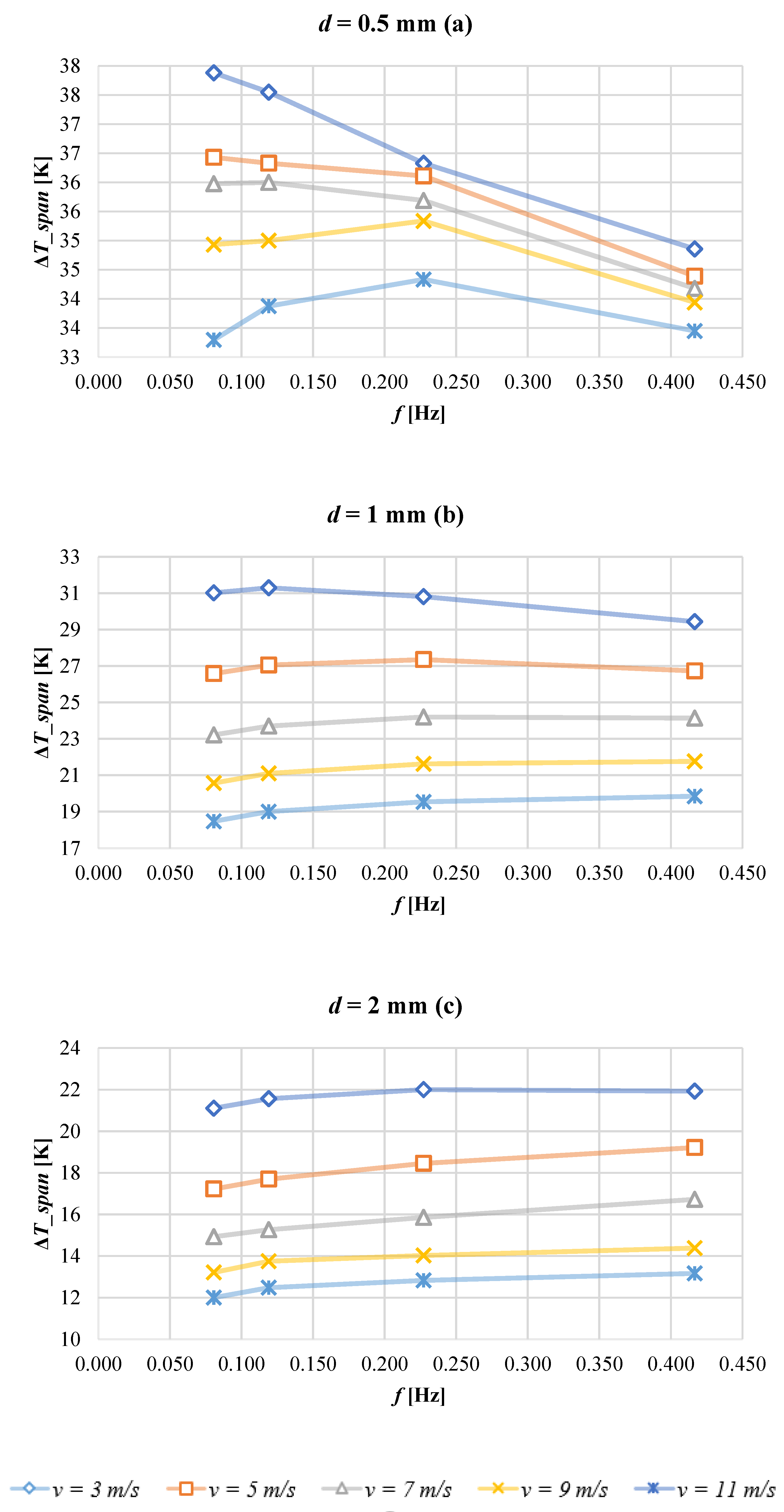
  • For all the investigated distances, at fixed frequency the temperature span decreases with the augmentation of the air velocity. Dually, at fixed air flow velocity, an optimal frequency that maximizes the temperature span exists. On equal velocity values, the optimal frequency grows if the distance between two wires increases.
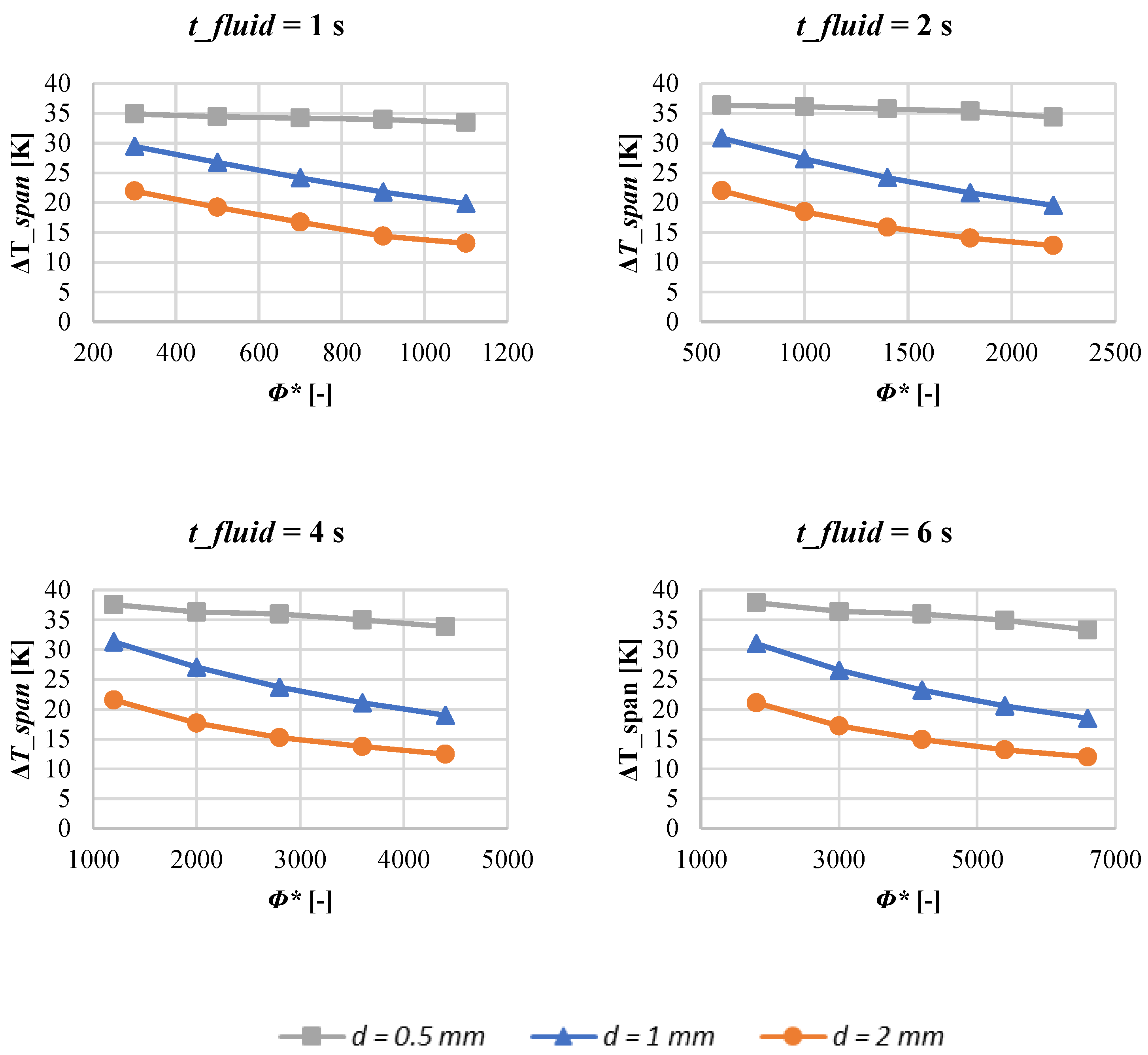
  • On equal air flow velocity and cycle frequency, the values of the temperature span decrease with the increasing of the distance between two wires (i.e., with the increasing of the air flow rate).
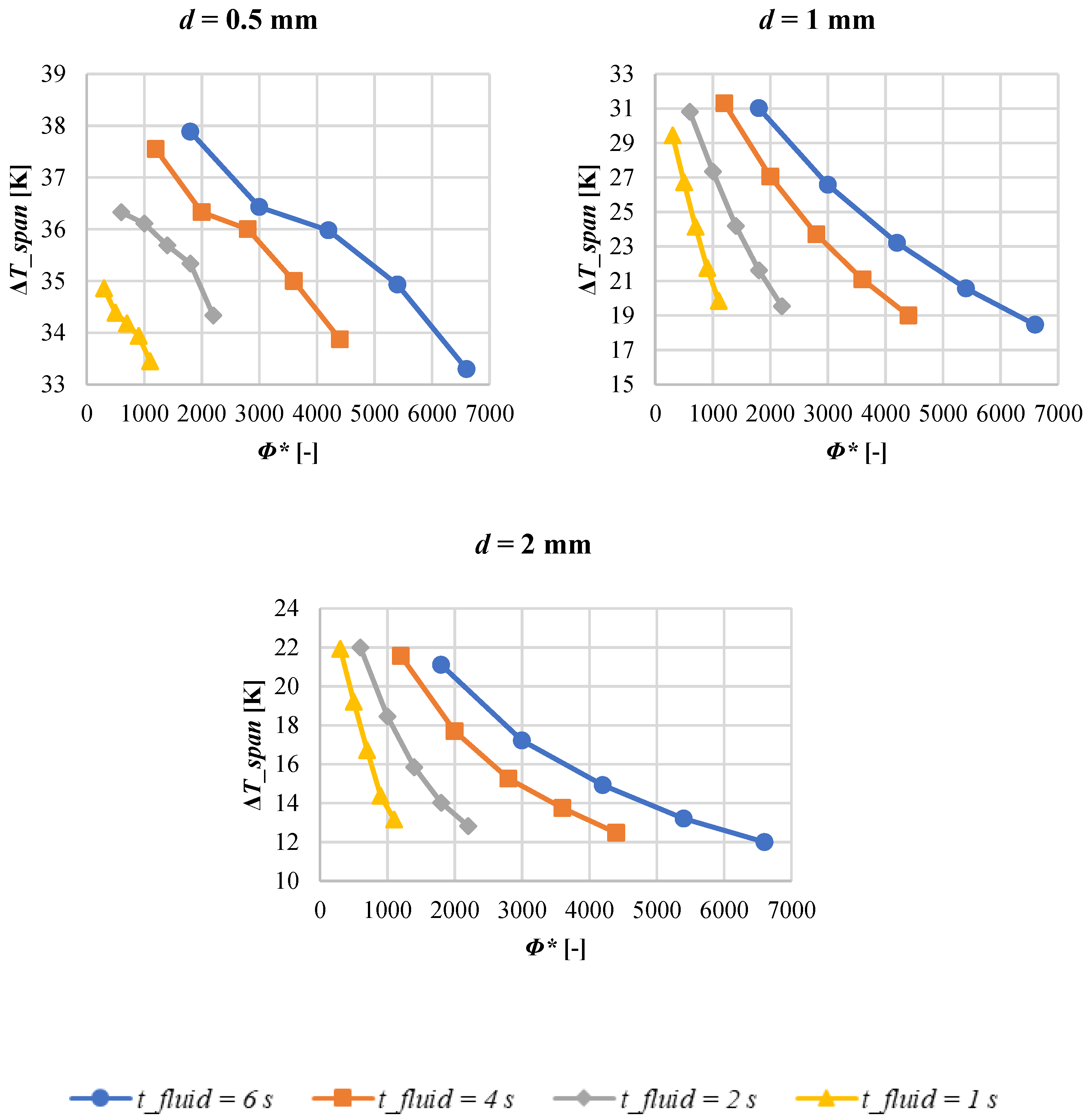
  • Analyzing the dependence of ΔTspan from the utilization factor ϕ, that is a parameter that correlates the overall impact of flow rate, frequency and geometrical dimensions, one can observe that the greater the time period of the convective heat exchange (at fixed distance between two wires), the higher the required utilization factors to achieve comparable values of temperature span. Moreover, at higher frequencies the curves of the ΔTspan vs. ϕ have a greater slope and therefore a stronger dependence on the speed variation.
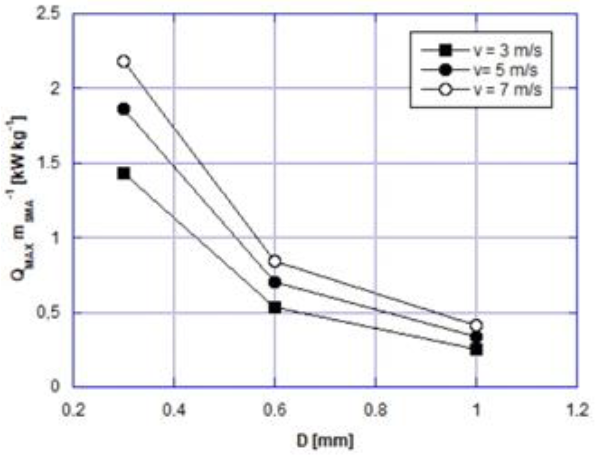
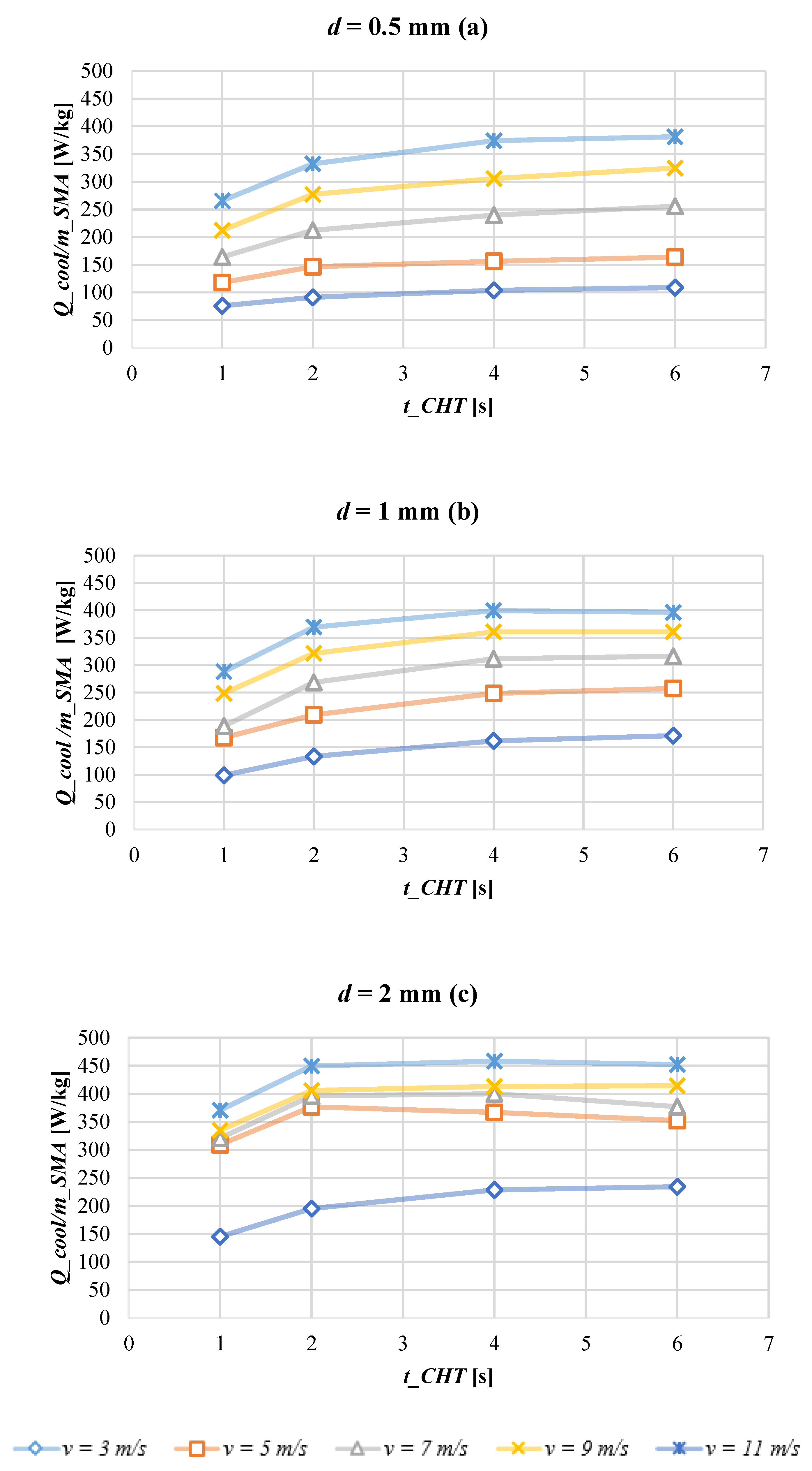
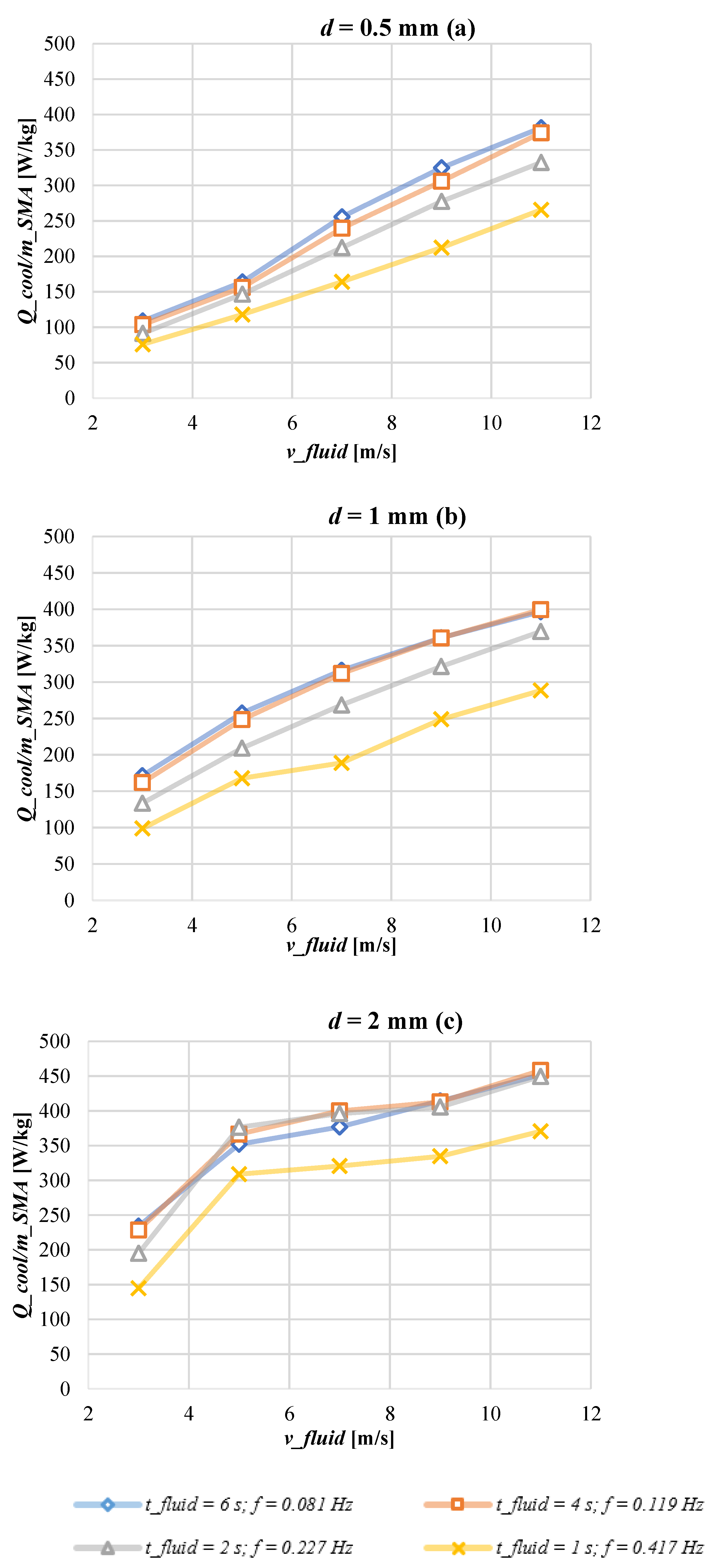
  • As opposed to temperature span, the overall consideration on the cooling power is that the greater the velocity of the air, the larger the values shown. Indeed, a trade-off in maximizing temperature span and cooling power exists. Anyhow, the effect of the increase in the cooling power with the velocity goes towards a saturation, so it is not advisable to increase the speed too much, equally to other operative parameters. At fixed velocity, the cooling power presents a maximum in correspondence of an optimal frequency that, on equal working conditions, is different from the one ensuring the maximization in temperature span. On equal air flow velocity and cycle frequency, there is a growth of the cooling power with the increasing of the distance between two wires (i.e., with the increase in the air flow rate).
In conclusion, stemming the existence of a trade-off between the maximization of temperature span and cooling power, in our opinion and with reference to the set of the investigated parameters of the operative conditions, the most suitable solution would be to operate with values located in the middle of the ranges. Specifically, the choice of: (i) tCHT = 4 s as time for the convective heat transfer process (that corresponds to 0.12 Hz as cycle frequency); (ii) 7 ms−1 as air flow velocity; (iii) 1.0 mm as optimal distance to place the wires, would ensure a temperature span and cooling power per mass unit of 23.7 K and 311.97 W kg−1.

Author Contributions

Conceptualization, A.G.; C.M.; L.C. and A.R.F.; methodology, A.G.; C.M.; software, A.G.; C.M.; L.C. and A.R.F. validation, C.M.; formal analysis, A.G.; C.M.; investigation, A.R.F.; resources A.G.; data curation, A.G.; C.M.; L.C. and A.R.F.; writing—original draft preparation, A.G.; C.M.; writing—review and editing, A.G.; C.M.; L.C. and A.R.F.; visualization, A.G.; C.M.; L.C. and A.R.F.; supervision, A.G.; project administration, A.G.; funding acquisition, A.G. All authors have read and agreed to the published version of the manuscript.

Funding

This research was funded through the project “SUSSTAINEBLE”—FISR2019 04798 granted by FISR—Fondo Integrativo Speciale per la Ricerca (Italian special supplementary fund for research).

Institutional Review Board Statement

Not applicable.

Informed Consent Statement

Not applicable.

Data Availability Statement

Not applicable.

Conflicts of Interest

The authors declare no conflict of interest.

Nomenclature

Roman Symbols
Aarea, m2
cspecific heat capacity, J kg−1 K−1
Ddiameter, mm
dDistance between two wires, mm
ffrequency, Hz
Gelastocaloric term, kJ m−3
HLatent heat, J g−1
hconvective heat transfer coefficient, W m−2 K−1
kthermal conductivity, W m−1 K−1
Llength of the wire, mm
mMass, kg
m ˙ flow rate, kg s−1
nnumber of times
ppressure, Pa
PrPrandtl number
Q ˙ power, W
q ˙ convective heat flux, W m−2
Ttemperature, K
ttime, s
ux-velocity field component, ms−1
Vvolume, m3
vy-velocity field component, ms−1
v velocity vector, ms−1
wloading/unloading work, Jg-1
xlongitudinal spatial coordinate, m
yorthogonal spatial coordinate, m
Greek symbols
Δfinite difference
δinfinitesimal difference
ε strain, N
ε ¯ infinitesimal quantity
θperiod of the AeR cycle, s
µdynamic viscosity, Pa s
υcinematic viscosity, m2 s−1
ξvolume fraction of the superelastic phase
ρdensity, kg m−3
σuniaxial stress, MPa
τconvective heat exchange transient constant, s
Φ utilization factor
ψprobability
Subscripts
AAustenitic
AMAustenite-to-Martensite transformation
adadiabatic
airair
Ccooling
CHTConvective Heat Transfer process
envenvironment
ffluid
loadloading
MMartensitic
MAMartensite-to-Austenite transformation
netnet
SMAShape Memory Alloy
spanspan
unloadunloading

References

  1. Montreal Protocol on Substances That Deplete the Ozone Layer; United Nation Environment Program (UN): New York, NY, USA, 1987.
  2. Kyoto Protocol to the United Nation Framework Convention on Climate Change; Kyoto, Japan, 1997.
  3. Heath, E.A. Amendment to the Montreal Protocol on Substances that Deplete the Ozone Layer (Kigali Amendment). Int. Leg. Mater. 2017, 56, 193–205. [Google Scholar] [CrossRef] [Green Version]
  4. The European Parliament and the Council. No 517/2014 of the European Parliament and of the Council of 16 April 2014 on fluorinated greenhouse gases and repealing Regulation (EC) No 842/2006 Text with EEA relevance. Off. J. Eur. Union L 2014. Available online: https://eur-lex.europa.eu/eli/reg/2014/517/oj (accessed on 11 May 2021).
  5. Aprea, C.; Greco, A.; Maiorino, A.; Masselli, C. The drop-in of HFC134a with HFO1234ze in a household refrigerator. Int. J. Therm. Sci. 2018, 127, 117–125. [Google Scholar] [CrossRef]
  6. Aprea, C.; Greco, A.; Maiorino, A. An experimental investigation of the energetic performances of HFO1234yf and its binary mixtures with HFC134a in a household refrigerator. Int. J. Refrig. 2017, 76, 109–117. [Google Scholar] [CrossRef]
  7. Molés, F.; Navarro-Esbrí, J.; Peris, B.; Mota-Babiloni, A.; Barragán-Cervera, Á.; Kontomaris, K.K. Low GWP alternatives to HFC-245fa in Organic Rankine Cycles for low temperature heat recovery: HCFO-1233zd-E and HFO-1336mzz-Z. Appl. Therm. Eng. 2014, 71, 204–212. [Google Scholar] [CrossRef]
  8. Mateu-Royo, C.; Navarro-Esbrí, J.; Mota-Babiloni, A.; Amat-Albuixech, M.; Molés, F. Thermodynamic analysis of low GWP alternatives to HFC-245fa in high-temperature heat pumps: HCFO-1224yd (Z), HCFO-1233zd (E) and HFO-1336mzz (Z). Appl. Therm. Eng. 2019, 152, 762–777. [Google Scholar] [CrossRef]
  9. Mateu-Royo, C.; Mota-Babiloni, A.; Navarro-Esbrí, J.; Barragán-Cervera, Á. Comparative analysis of HFO-1234ze (E) and R-515B as low GWP alternatives to HFC-134a in moderately high temperature heat pumps. Int. J. Refrig. 2021, 124, 197–206. [Google Scholar] [CrossRef]
  10. Mota-Babiloni, A.; Navarro-Esbrí, J.; Barragán-Cervera, Á.; Molés, F.; Peris, B. Analysis based on EU Regulation No 517/2014 of new HFC/HFO mixtures as alternatives of high GWP refrigerants in refrigeration and HVAC systems. Int. J. Refrig. 2015, 52, 21–31. [Google Scholar] [CrossRef]
  11. Greco, A.; Vanoli, G.P. Experimental two-phase pressure gradients during evaporation of pure and mixed refrigerants in a smooth horizontal tube. Comparison with correlations. Heat Mass Transf. 2006, 42, 709–725. [Google Scholar] [CrossRef]
  12. Greco, A.; Vanoli, G.P. Flow boiling heat transfer with HFC mixtures in a smooth horizontal tube. Part II: Assessment of predictive methods. Exp. Therm. Fluid Sci. 2005, 29, 199–208. [Google Scholar] [CrossRef]
  13. Greco, A.; Mastrullo, R.; Palombo, A. R407C as an alternative to R22 in vapour compression plant: An experimental study. Int. J. Energy Res. 1997, 21, 1087–1098. [Google Scholar] [CrossRef]
  14. Mortada, S.; Zoughaib, A.; Arzano-Daurelle, C.; Clodic, D. Boiling heat transfer and pressure drop of R-134a and R-1234yf in minichannels for low mass fluxes. Int. J. Refrig. 2012, 35, 962–973. [Google Scholar] [CrossRef]
  15. Heredia-Aricapa, Y.; Belman-Flores, J.M.; Mota-Babiloni, A.; Serrano-Arellano, J.; García-Pabón, J.J. Overview of low GWP mixtures for the replacement of HFC refrigerants: R134a, R404A and R410A. Int. J. Refrig. 2020, 111, 113–123. [Google Scholar] [CrossRef]
  16. Aprea, C.; Greco, A.; Maiorino, A. The substitution of R134a with R744: An exergetic analysis based on experimental data. Int. J. Refrig. 2013, 36, 2148–2159. [Google Scholar] [CrossRef]
  17. Barbato, M.; Cirillo, L.; Menditto, L.; Moretti, R.; Nardini, S. Feasibility study of a geothermal energy system for indoor swimming pool in Campi Flegrei area. Therm. Sci. Eng. Prog. 2018, 6, 421–425. [Google Scholar] [CrossRef]
  18. Cirillo, L.; Della Corte, A.; Nardini, S. Feasibility study of solar cooling thermally driven system configurations for an office building in Mediterranean area. Int. J. Heat Technol. 2016, 34, 472–480. [Google Scholar] [CrossRef]
  19. D’Agostino, D.; Greco, A.; Masselli, C.; Minichiello, F. The employment of an earth-to-air heat exchanger as pre-treating unit of an air conditioning system for energy saving: A comparison among different worldwide climatic zones. Energy Build. 2020, 229, 110517. [Google Scholar] [CrossRef] [PubMed]
  20. Cascetta, F.; Cirillo, L.; Della Corte, A.; Nardini, S. Comparison between different solar cooling thermally driven system solutions for an office building in Mediterranean Area. Int. J. Heat Technol. 2017, 35, 130–138. [Google Scholar] [CrossRef]
  21. Cascetta, F.; Di Lorenzo, R.; Nardini, S.; Cirillo, L. A Trnsys Simulation of a Solar-Driven Air Refrigerating System for a Low-Temperature Room of an Agro-Industry site in the Southern part of Italy. Energy Procedia 2017, 126, 329–336. [Google Scholar] [CrossRef]
  22. Renaldi, R.; Miranda, N.D.; Khosla, R.; McCulloch, M.D. Patent landscape of not-in-kind active cooling technologies between 1998 and 2017. J. Clean. Prod. 2021, 126507. [Google Scholar] [CrossRef]
  23. Qian, S.; Nasuta, D.; Rhoads, A.; Wang, Y.; Geng, Y.; Hwang, Y.; Radermacher, R.; Takeuchi, I. Not-in-kind cooling technologies: A quantitative comparison of refrigerants and system performance. Int. J. Refrig. 2016, 62, 177–192. [Google Scholar] [CrossRef] [Green Version]
  24. Brown, J.S.; Domanski, P.A. Review of alternative cooling technologies. Appl. Therm. Eng. 2014, 64, 252–262. [Google Scholar] [CrossRef]
  25. Fähler, S. Caloric effects in ferroic materials: New concepts for cooling. Energy Technol. 2018, 6, 1394–1396. [Google Scholar] [CrossRef] [Green Version]
  26. Aprea, C.; Greco, A.; Maiorino, A.; Masselli, C. The employment of caloric-effect materials for solid-state heat pumping. Int. J. Refrig. 2020, 109, 1–11. [Google Scholar] [CrossRef]
  27. Kitanovski, A.; Plaznik, U.; Tomc, U.; Poredoš, A. Present and future caloric refrigeration and heat-pump technologies. Int. J. Refrig. 2015, 57, 288–298. [Google Scholar] [CrossRef]
  28. Aprea, C.; Greco, A.; Maiorino, A.; Masselli, C. The environmental impact of solid-state materials working in an active caloric refrigerator compared to a vapor compression cooler. Int. J. Heat Technol. 2018, 36, 1155–1162. [Google Scholar] [CrossRef]
  29. Aprea, C.; Greco, A.; Maiorino, A.; Masselli, C. The use of barocaloric effect for energy saving in a domestic refrigerator with ethylene-glycol based nanofluids: A numerical analysis and a comparison with a vapor compression cooler. Energy 2020, 190, 116404. [Google Scholar] [CrossRef]
  30. Aprea, C.; Greco, A.; Maiorino, A.; Masselli, C. Analyzing the energetic performances of AMR regenerator working with different magnetocaloric materials: Investigations and viewpoints. Int. J. Heat Technol. 2017, 35, S383–S390. [Google Scholar] [CrossRef]
  31. Aprea, C.; Greco, A.; Maiorino, A.; Masselli, C. A comparison between different materials in an active electrocaloric regenerative cycle with a 2D numerical model. Int. J. Refrig. 2016, 69, 369–382. [Google Scholar] [CrossRef]
  32. Qian, S.; Geng, Y.; Wang, Y.; Ling, J.; Hwang, Y.; Radermacher, R.; Cui, J. A review of elastocaloric cooling: Materials, cycles and system integrations. Int. J. Refrig. 2016, 64, 1–19. [Google Scholar] [CrossRef] [Green Version]
  33. Gschneidner, K.A., Jr.; Pecharsky, V.K.; Pecharsky, A.O.; Zimm, C.B. Recent developments in magnetic refrigeration. Mater. Sci. Forum 1999, 315, 69–76. [Google Scholar] [CrossRef]
  34. Clot, P.; Viallet, D.; Allab, F.; Kedous-Lebouc, A.; Fournier, J.M.; Yonnet, J.P. A magnet-based device for active magnetic regenerative refrigeration. IEEE Trans. Magn. 2003, 39, 3349–3351. [Google Scholar] [CrossRef]
  35. Von Ranke, P.J.; De Oliveira, N.A.; Mello, C.; Carvalho, A.M.G.; Gama, S. Analytical model to understand the colossal magnetocaloric effect. Phys. Rev. B 2005, 71, 054410. [Google Scholar] [CrossRef]
  36. Gao, Q.; Yu, B.F.; Wang, C.F.; Zhang, B.; Yang, D.X.; Zhang, Y. Experimental investigation on refrigeration performance of a reciprocating active magnetic regenerator of room temperature magnetic refrigeration. Int. J. Refrig. 2006, 29, 1274–1285. [Google Scholar] [CrossRef]
  37. Allab, F.; Kedous-Lebouc, A.; Fournier, J.M.; Yonnet, J.P. Numerical modeling for active magnetic regenerative refrigeration. IEEE Trans. Magn. 2005, 41, 3757–3759. [Google Scholar] [CrossRef]
  38. Aprea, C.; Greco, A.; Maiorino, A. A numerical analysis of an active magnetic regenerative cascade system. Int. J. Energy Res. 2011, 35, 177–188. [Google Scholar] [CrossRef]
  39. Aprea, C.; Greco, A.; Maiorino, A. Modelling an active magnetic refrigeration system: A comparison with different models of incompressible flow through a packed bed. Appl. Therm. Eng. 2012, 36, 296–306. [Google Scholar] [CrossRef]
  40. Aprea, C.; Greco, A.; Maiorino, A. The use of the first and of the second order phase magnetic transition alloys for an AMR refrigerator at room temperature: A numerical analysis of the energy performances. Energy Convers. Manag. 2013, 70, 40–55. [Google Scholar] [CrossRef]
  41. Yu, B.F.; Gao, Q.; Zhang, B.; Meng, X.Z.; Chen, Z. Review on research of room temperature magnetic refrigeration. Int. J. Refrig. 2003, 26, 622–636. [Google Scholar] [CrossRef]
  42. Greco, A.; Aprea, C.; Maiorino, A.; Masselli, C. A review of the state of the art of solid-state caloric cooling processes at room-temperature before 2019. Int. J. Refrig. 2019, 106, 66–88. [Google Scholar] [CrossRef]
  43. Goetzler, W.; Zogg, R.; Young, J.; Johnson, C. Energy Savings Potential and RD&D Opportunities for Non-Vapor-Compression HVAC Technologies; US Department of Energy, Office of Energy Efficiency and Renewable Energy, Building Technologies Office: Burlington, VT, USA, 2014.
  44. Technology Roadmap in Preparatory/Review Study on Commission Regulation (EC) No. 643/2009 with Regard to Ecodesign Requirements for Household Refrigeration Appliances and Commission Delegated Regulation (EU) No. 1060/2010 with Regard to Energy Labelling of Household Refrigeration Appliances. Final Roadmap Report. 2016. Available online: https://www.eup-network.de/fileadmin/user_upload/Household_Refrigeration_Review_TECHNOLOGY_ROADMAP_FINAL_20160304.pdf (accessed on 10 April 2021).
  45. Jani, J.M.; Leary, M.; Subic, A.; Gibson, M.A. A review of shape memory alloy research, applications and opportunities. Mater. Des. 2014, 56, 1078–1113. [Google Scholar] [CrossRef]
  46. Buchler, W.J. Effect of low-temperature phase changes on the mechanical properties of alloys near composition TiNi. J. Apply Phys. 1963, 34, 1475–1477. [Google Scholar] [CrossRef]
  47. Kabirifar, P.; Žerovnik, A.; Ahčin, Ž.; Porenta, L.; Brojan, M.; Tušek, J. Elastocaloric Cooling: State-of-the-art and Future Challenges in Designing Regenerative Elastocaloric Devices. Stroj. Vestn. J. Mech. Eng. 2019, 65, 615–630. [Google Scholar] [CrossRef] [Green Version]
  48. Cui, J.; Wu, Y.; Muehlbauer, J.; Hwang, Y.; Radermacher, R.; Fackler, S.; Wuttig, M.; Takeuchi, I. Demonstration of high efficiency elastocaloric cooling with large ΔT using NiTi wires. Appl. Phys. Lett. 2012, 101, 073904. [Google Scholar] [CrossRef] [Green Version]
  49. Manca, O.; Cirillo, L.; Nardini, S.; Buonomo, B.; Ercole, D. Experimental investigation on fluid dynamic and thermal behavior in confined impinging round jets in aluminum foam. Energy Procedia 2016, 101, 1095–1102. [Google Scholar] [CrossRef]
  50. Buonomo, B.; Cirillo, L.; Manca, O.; Mansi, N.; Nardini, S. Confined impinging jets in porous media. J. Phys. Conf. Ser. 2016, 745, 032142. [Google Scholar] [CrossRef] [Green Version]
  51. Alaneme, K.K.; Okotete, E.A. Reconciling viability and cost-effective shape memory alloy options—A review of copper and iron based shape memory metallic systems. Eng. Sci. Technol. Int. J. 2016, 19, 1582–1592. [Google Scholar] [CrossRef] [Green Version]
  52. Patel, S.; Chauhan, A.; Vaish, R.; Thomas, P. Elastocaloric and barocaloric effects in polyvinylidene di-fluoride-based polymers. Appl. Phys. Lett. 2016, 108, 072903. [Google Scholar] [CrossRef]
  53. Xie, Z.; Sebald, G.; Guyomar, D. Comparison of elastocaloric effect of natural rubber with other caloric effects on different-scale cooling application cases. Appl. Therm. Eng. 2017, 111, 914–926. [Google Scholar] [CrossRef]
  54. Xie, Z.; Sebald, G.; Guyomar, D. Elastocaloric effect dependence on pre-elongation in natural rubber. Appl. Phys. Lett. 2015, 107, 081905. [Google Scholar] [CrossRef]
  55. Schmidt, M.; Schütze, A.; Seelecke, S. Scientific test setup for investigation of shape memory alloy based elastocaloric cooling processes. Int. J. Refrig. 2015, 54, 88–97. [Google Scholar] [CrossRef]
  56. Qian, S.; Alabdulkarem, A.; Ling, J.; Muehlbauer, J.; Hwang, Y.; Radermacher, R.; Takeuchi, I. Performance enhancement of a compressive thermoelastic cooling system using multi-objective optimization and novel designs. Int. J. Refrig. 2015, 57, 62–76. [Google Scholar] [CrossRef] [Green Version]
  57. Tušek, J.; Engelbrecht, K.; Eriksen, D.; Dall’Olio, S.; Tušek, J.; Pryds, N. A regenerative elastocaloric heat pump. Nat. Energy 2016, 1, 1–6. [Google Scholar] [CrossRef]
  58. Kirsch, S.M.; Welsch, F.; Michaelis, N.; Schmidt, M.; Wieczorek, A.; Frenzel, J.; Seelecke, S. NiTi-Based Elastocaloric Cooling on the Macroscale: From Basic Concepts to Realization. Energy Technol. 2018, 6, 1567–1587. [Google Scholar] [CrossRef]
  59. Kirsch, S.; Welsch, F.; Michaelis, N.; Scmidt, M.; Schütze, A.; Seelecke, S. Continuously operating elastocaloric cooling device based on shape memory alloys: Development and realization. In Proceedings of the 8th International Conference on Caloric Cooling (Thermag VIII), Darmstadt, Germany, 16–20 September 2018. [Google Scholar]
  60. Snodgrass, R.; Erickson, D. A two-stage elastocaloric cooler for increased temperature span. In Proceedings of the Shape Memory and Superelastic Technology Conference, Konstanz, Germany, 13–17 May 2019. [Google Scholar]
  61. Tušek, J.; Engelbrecht, K.; Millán-Solsona, R.; Manosa, L.; Vives, E.; Mikkelsen, L.P.; Pryds, N. The elastocaloric effect: A way to cool efficiently. Adv. Energy Mater. 2015, 5, 1500361. [Google Scholar] [CrossRef]
  62. Qian, S.; Ling, J.; Hwang, Y.; Radermacher, R.; Takeuchi, I. Thermodynamics cycle analysis and numerical modeling of thermoelastic cooling systems. Int. J. Refrig. 2015, 56, 65–80. [Google Scholar] [CrossRef] [Green Version]
  63. Qian, S.; Yuan, L.; Yu, J.; Yan, G. Numerical modeling of an active elastocaloric regenerator refrigerator with phase transformation kinetics and the matching principle for materials selection. Energy 2017, 141, 744–756. [Google Scholar] [CrossRef]
  64. Qian, S.; Yuan, L.; Hou, H.; Takeuchi, I. Accurate prediction of work and coefficient of performance of elastocaloric materials with phase transformation kinetics. Sci. Technol. Built Environ. 2018, 24, 673–684. [Google Scholar] [CrossRef]
  65. Luo, D.; Feng, Y.; Verma, P. Modeling and analysis of an integrated solid state elastocaloric heat pumping system. Energy 2017, 130, 500–514. [Google Scholar] [CrossRef]
  66. Welsch, F.; Kirsch, S.M.; Michaelis, N.; Schmidt, M.; Schütze, A.; Seelecke, S. Continuously Operating Elastocaloric Cooling Device based on Shape Memory Alloys: Development and Realization. In Proceedings of the Thermag VII: International Conference on Caloric Cooling 2018, Darmstadt, Germany, 16–20 September 2018. [Google Scholar]
  67. Welsch, F.; Ullrich, J.; Ossmer, H.; Schmidt, M.; Kohl, M.; Chluba, C.; Quandt, E.; Schütze, A.; Seelecke, S. Numerical simulation and experimental investigation of the elastocaloric cooling effect in sputter-deposited TiNiCuCo thin films. Contin. Mech. Thermodyn. 2018, 30, 53–68. [Google Scholar] [CrossRef]
  68. Ossmer, H.; Lambrecht, F.; Gültig, M.; Chluba, C.; Quandt, E.; Kohl, M. Evolution of temperature profiles in TiNi films for elastocaloric cooling. Acta Mater. 2014, 81, 9–20. [Google Scholar] [CrossRef]
  69. Tušek, J.; Engelbrecht, K.; Mañosa, L.; Vives, E.; Pryds, N. Understanding the thermodynamic properties of the elastocaloric effect through experimentation and modelling. Shape Mem. Superelasticity 2016, 2, 317–329. [Google Scholar] [CrossRef] [Green Version]
  70. Aprea, C.; Greco, A.; Maiorino, A.; Masselli, C. Energy performances and numerical investigation of solid-state magneto-caloric materials used as refrigerant in an active magnetic regenerator. Therm. Sci. Eng. Prog. 2018, 6, 370–379. [Google Scholar] [CrossRef]
  71. Tušek, J.; Kitanovski, A.; Prebil, I.; Poredoš, A. Dynamic operation of an active magnetic regenerator (AMR): Numerical optimization of a packed-bed AMR. Int. J. Refrig. 2011, 34, 1507–1517. [Google Scholar] [CrossRef]
Figure 1. (a) The bunch of elastocaloric wires. (b) A zoom on two wires. The blue arrow represents a velocity whose value is object of the investigation.
Magnetochemistry 07 00067 g001
Figure 2. A schematic of the experimental device.
Magnetochemistry 07 00067 g002
Figure 3. Experimental validation of the model. The adiabatic temperature change due to elastocaloric effect of a Ni50.4Ti49.6 wire: comparison between numerical and experimental results vs. strain rate.
Magnetochemistry 07 00067 g003
Figure 4. Estimate of the maximum cooling power per mass unit in a wire vs. the diameter, parametrized for air velocity.
Magnetochemistry 07 00067 g004
Figure 5. Temperature span as a function of the cycle frequency parametrized for air velocity when the distance between two wires is: (a) 0.5 mm; (b) 1.0 mm; (c) 2.0 mm.
Magnetochemistry 07 00067 g005
Figure 6. Temperature span as a function of the utilization factor, parametrized for the distance between two wires. Each subplot refers to a tested tCHT dataset.
Magnetochemistry 07 00067 g006
Figure 7. Temperature span as a function of the utilization factor, parametrized for the convective heat transfer time. Each subplot refers to a tested dataset of distance between two wires.
Magnetochemistry 07 00067 g007
Figure 8. Cooling power per mass unit as a function of the time for the convective Heat Transfer process parametrized for fluid velocity when the distance between two wires is: (a) 0.5 mm; (b) 1.0 mm; (c) 2.0 mm.
Magnetochemistry 07 00067 g008
Figure 9. Cooling power per mass unit as function of the velocity parametrized for the convective heat transfer process when the distance between two wires is: (a) 0.5 mm; (b) 1.0 mm; (c) 2.0 mm.
Magnetochemistry 07 00067 g009
Publisher’s Note: MDPI stays neutral with regard to jurisdictional claims in published maps and institutional affiliations.

