Article

Lightweight Polymer-Carbon Composite Current Collector for Lithium-Ion Batteries

1
Fraunhofer Institute for Ceramic Technologies and Systems (IKTS), 01277 Dresden, Germany
2
Leibniz Institute of Polymer Research Dresden e.V. (IPF), 01069 Dresden, Germany
*
Author to whom correspondence should be addressed.
Submission received: 16 October 2020 / Revised: 20 November 2020 / Accepted: 30 November 2020 / Published: 8 December 2020
(This article belongs to the Special Issue Lithium-Ion Batteries: Latest Advances and Prospects)

Abstract

:
A hermetic dense polymer-carbon composite-based current collector foil (PCCF) for lithium-ion battery applications was developed and evaluated in comparison to state-of-the-art aluminum (Al) foil collector. Water-processed LiNi0.5Mn1.5O4 (LMNO) cathode and Li4Ti5O12 (LTO) anode coatings with the integration of a thin carbon primer at the interface to the collector were prepared. Despite the fact that the laboratory manufactured PCCF shows a much higher film thickness of 55 µm compared to Al foil of 19 µm, the electrode resistance was measured to be by a factor of 5 lower compared to the Al collector, which was attributed to the low contact resistance between PCCF, carbon primer and electrode microstructure. The PCCF-C-primer collector shows a sufficient voltage stability up to 5 V vs. Li/Li+ and a negligible Li-intercalation loss into the carbon primer. Electrochemical cell tests demonstrate the applicability of the developed PCCF for LMNO and LTO electrodes, with no disadvantage compared to state-of-the-art Al collector. Due to a 50% lower material density, the lightweight and hermetic dense PCCF polymer collector offers the possibility to significantly decrease the mass loading of the collector in battery cells, which can be of special interest for bipolar battery architectures.

1. Introduction

Lithium-ion batteries play an important role in the development of electric vehicles and portable electronic devices. Bipolar battery concepts [1,2] utilize the connection of multiple cells in series to form a battery stack. This approach avoids the use of numerous passive components and parts usually required for packaging as well as external electrical wiring, which lowers the overall electrical resistance, volume, weight, complexity and cost of the battery.
In a bipolar battery architecture, anode and cathode electrodes are coated on both sides of the same current collector (bipolar plate). To avoid internal short-circuits between the unit cells, this collector has to be pore free. Since anode and cathode operate in different cell potential ranges, the collector material has to be stable against corrosion in a wide voltage range (e.g., 0 to >5 V vs. Li/Li+). State-of-the-art lithium-ion batteries use thin aluminum (Al) and copper (Cu) foils as current collectors for cathode and anode, respectively [3,4]. Al shows a destructive alloying reaction below 1 V vs. Li/Li+, which falls within the potential window of state-of-the-art carbon anodes [5]. That is why Al is only used as cathode collector or in combination with high voltage anodes like Li4Ti5O12 (~1.5 V vs. Li/Li+). On the other hand, Cu is dissolved above 3.5 V vs. Li/Li+, the potential window of common oxide cathodes, which limits the applicability of Cu collector to the anode side. To overcome this issue, bimetal collectors with a combination of Al-Ni or Al-Cu were developed [6,7,8,9,10]. However, this leads to increased costs and there are considerable difficulties in industrial implementation. These comprise residual pores, which can lead to short circuits [7]. During welding processes above 120 °C, Al and Cu form intermetallic compounds, which are brittle and lead to a poor strength and high electrical resistance [11,12,13].
In state-of-the-art lithium-ion batteries, metallic collectors can represent a significant percentage of an electrode weight [14] and they exhibit corrosion problems during processing of water-based electrode slurries [15] as well as with electrolyte components [5,16]. Especially for novel mechanical flexible battery concepts, alternative current collector materials were developed based on carbon, coated paper, textiles and conductive polymers [17,18]. Carbon collectors based on graphite, carbon fibers, carbon nanotubes and graphene offer a low density and high stability over a wide range of electrode potentials [19]. However, their packing density and mechanical stability is limited, which makes it difficult to achieve benefits on the macro-scale of battery performance. Residual porosity in such carbon collectors is the main hindrance to use them for bipolar battery concepts, since short circuits can occur.
The use of electrically conductive polymer composites, that remain electrochemically stable in the whole potential window of the battery, would greatly simplify the process of manufacturing of bipolar collectors and the processing of lithium-ion batteries [20]. Further, polymer composites can lead to more lightweight collectors, since Al and Cu have correspondingly moderate and high densities (2.7 g/cm3 and 8.9 g/cm3 respectively) in comparison to polymers like poly(vinylidene fluoride) (PVDF) (1.8 g/cm3) or polyethylene (PE) and polypropylene (PP) (0.9 g/cm3). Due to applicability, in terms of a required mechanical strength and secure handling during electrode production, the thickness of metal collectors is limited to approx. 10 to 30 µm. Today, several technical applications use much thinner polymer foils and there is a high probability that even battery-compatible polymer collectors can be developed.
We recently published the attractive electronic properties of polymer-carbon composite foils (PCCF) based on PVDF polymer [21,22,23]. In this study, we present the processing, electrochemical stability and performance of a PVDF polymer carbon nanocomposite current collector, which can be extruded to a thin hermetic dense collector foil and processed in a roll-to-roll process. The applicability for lithium-ion battery applications was studied based on water processed LiNi0.5Mn1.5O4 (LMNO) cathode and Li4Ti5O12 (LTO) anodes coatings with the integration of a thin carbon primer at the interface to the collector. For comparison reasons comparable electrodes were also fabricated on a thin Al collector. We used LMNO and LTO active materials, since they offer a more environmentally friendly approach (no cobalt component) and can be charged to high voltages. The applicability of different current collector materials depends, beside aspects of processing and costs, on a low electrical resistance (influence on the overall cell resistance and capacity losses with increasing C-rates) and the chemical compatibility to other cell components (e.g., active materials and electrolyte). These aspects will be discussed in this paper for PCCF in comparison to Al-foil collector.

2. Results and Discussion

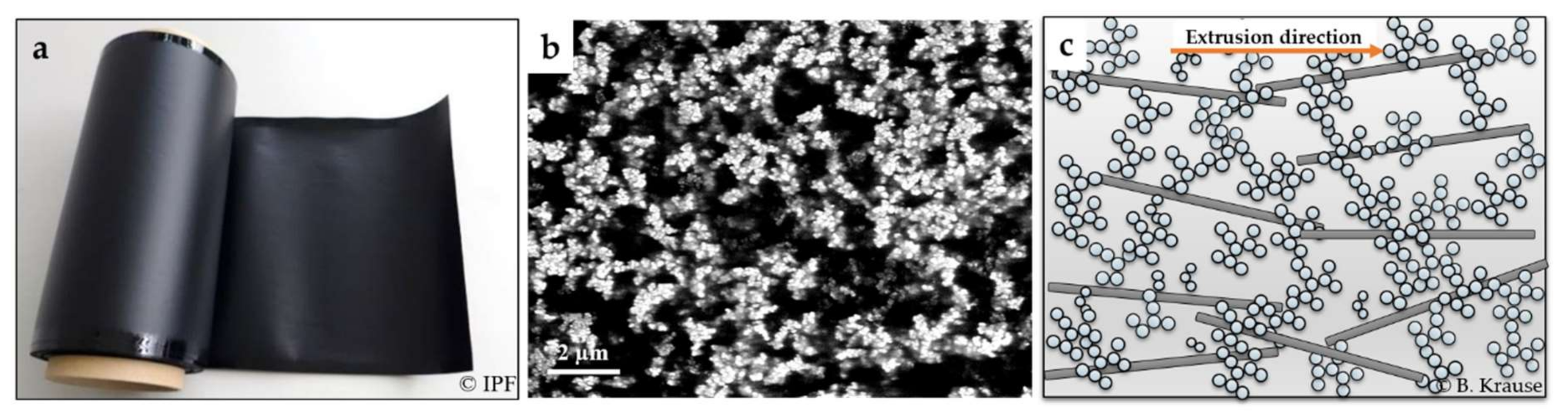
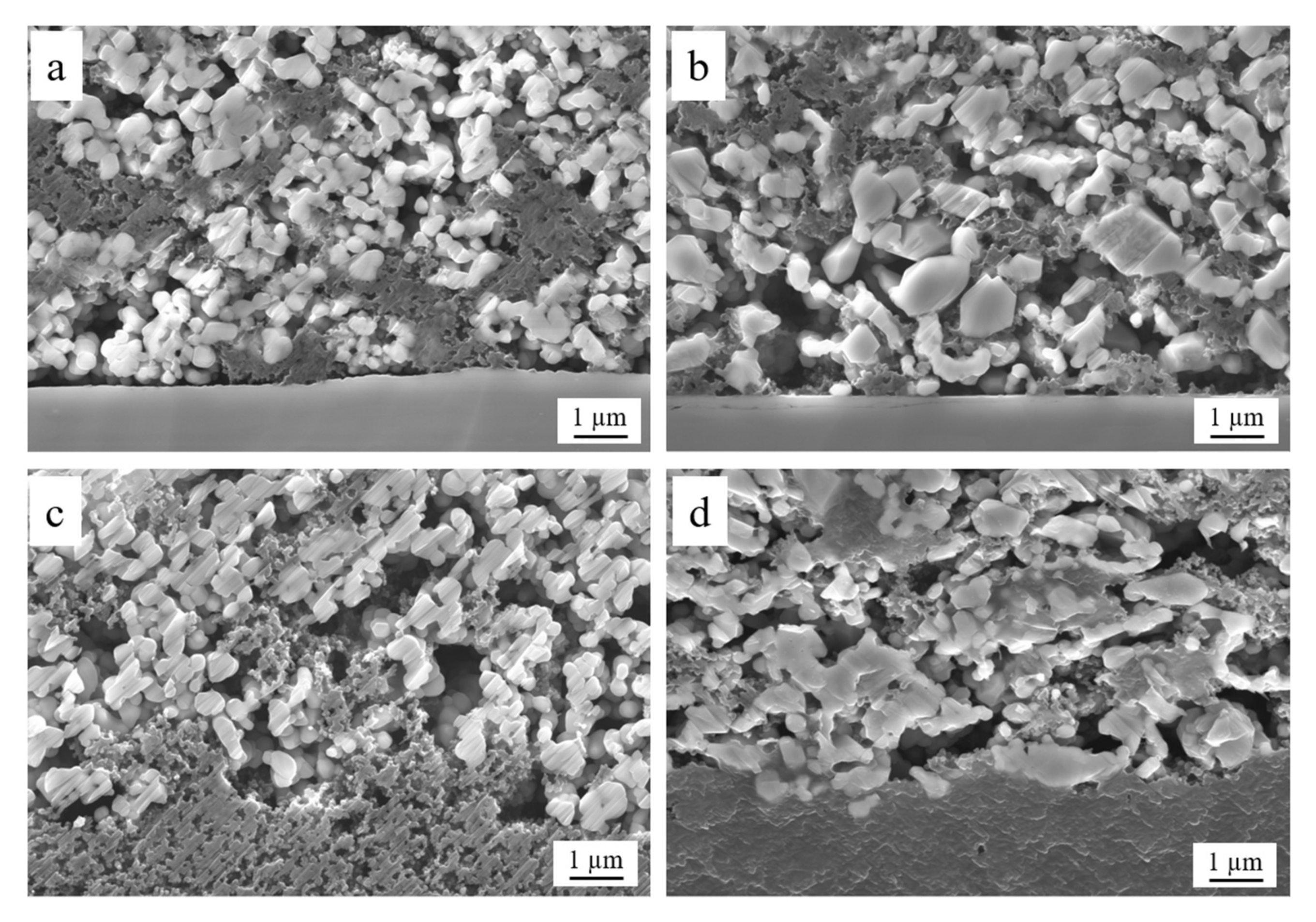
2.1. Characterization of the Polymer-Carbon Composite and Electrodes

Figure 1a shows the developed polymer-carbon composite foil (PCCF) after film extrusion. The process allows the handling in roll-to-roll process, which is state of the art in today´s battery electrode manufacturing. Due to the extrusion process, the PCCF shows at the edges a small shiny strip (~1 cm) with a different thickness and roughness, which can be cut off prior to the electrode coating process. Figure 1b shows the PCCF microstructure, where the carbon nanotube and carbon black filler particles are generally homogeneously distributed in the PVDF polymer matrix. In the SEM-CCI image, the 3 wt.-% CB dominates the appearance; however, an orientation of the CNT particles in the extrusion direction occurs. SEM-CCI images of foils with lower CB content show the discussed CNT filler orientation more clearly (Figure 5 in [23]. Due to the high aspect ratio of the CNTs, the particles rotate in the viscous melt during flowing through the extrusion die and are oriented in plane, whereas the small spherical carbon black particles are hardly oriented and thus connect the CNTs in the through-plane direction (see schematic Figure 1c). This particular microstructure will lead to differences in mechanical and electrical properties in dependence on PCCF orientation as discussed below and in Section 2.2.1.
The microstructure in Figure 1b may create the impression, that the PCCF is porous. However, this is not the fact, since the PCCF proved to be hermetically dense based on results of gas leakage test with helium (1.8 × 10⁻⁷ mbar·L/s) and air (1 × 10⁻¹² mbar·L/s, equals detection limit of equipment). With this hermetic density, the PCCF can separate cathode and anode half cells in bipolar cell architectures, where no liquid electrolyte will penetrate trough.
The mechanical properties of the PCCF collector in comparison to those of the battery grade Al collector are summarized in Table 1. The results show for PCCF higher values of the elastic modulus and tensile strength parallel to the extrusion direction compared to perpendicular to it, which is attributed to the orientation effect of the CNT particles during film extrusion. The elongation at break is comparable and independently of orientation. The Al collector, which is a strain-hardened aluminum foil (H18), shows higher tensile strength (>135 MPa according to [24]) and elastic modulus, but its elongation at break is lower compared to PCCF. Nevertheless, we demonstrated successfully the applicability of this PCCF foil in an industrial manufacturing machine (roll-to-roll coating) for battery electrodes [25]. In comparison to standard Al-foil, one adjustment needed was the implementation of special electrically driven rolls at the front end of the coater that push the PCCF without applying high pulling forces during the coating process, which will otherwise cause an unwanted elongation of the PCCF.
The surface topography and roughness of the extruded PCCF collector are shown in Figure 2. Over the scanned 600 µm × 600 µm area the maximum differences in height is 6 µm, which equals to 10% of thickness. The overall homogeneity of the PCCF surface is quite good; the roughness can be correlated to the existence of small agglomerates of CNT and carbon black filler particles. This residual roughness can be beneficial for the later electrode coating process, since highly smooth polymer surfaces are usually difficult to coat with functional films. Especially, the adhesion of coated films on smooth and dense fluorine-containing polymer surfaces is challenging, due to their low surface energy [26]. The positive effect of an increased collector roughness is also known from Al collector foils, where special etching techniques are applied to increase the Al surface roughness, which leads to a better electrode adhesion [27].
Table 2 summarizes the PCCF and Al collector materials used in this study. Prior to coating with electrodes, the PCCF was coated with a thin C-primer on both sides to reduce the electrical contact resistance between electrode and PCCF and to homogenize the electrical conductivity in plane at the interface to the active electrode layer. By comparing uncoated and C-primer coated PCCF, the C-primer film thickness and area weight were determined to be 7.5 ± 1.0 µm and 1.1 ± 0.1 mg/cm2 (both sides in sum).
Figure 3 shows the cross section of the C-primer coated on both sides of the PCCF and the interface microstructure between PCCF, C-primer and LTO electrode. In Figure 3a a variation of the PCCF thickness and C-primer layer thickness is visible. Such variations are common by using R&D laboratory equipment, but they can usually be avoided if industry relevant scale production and machinery are applied. Figure 3b,c show an excellent surface coverage and composite formation between C-primer and PCCF or active electrode layer, respectively.
Table 3 summarizes geometrical parameters and properties of the prepared LTO and LMNO electrode coatings on both types of current collectors. The initial porosity of the dried electrodes was 63 to 71 vol.-%, which was significantly reduced by the lamination densification down to ~40 vol.-%. Based on the information of the uncoated collector substrates (Table 2), the active electrode layer thickness was calculated to be 69 to 79 µm (LTO) and 63 to 64 µm (LMNO).
Figure 4 shows the interface between LTO and LMNO active electrodes on both current collectors. The interface microstructure between the C-primer of the PCCF and the active electrodes seems more interlocked in each other (Figure 4c,d) compared to the electrodes on the smooth Al collector (Figure 4a,b). Usually such carbon primer is not used in standard lithium-ion batteries with metal foil collectors, since it leads to additional processing steps and costs.

2.2. Electrical and Electrochemical Characterization

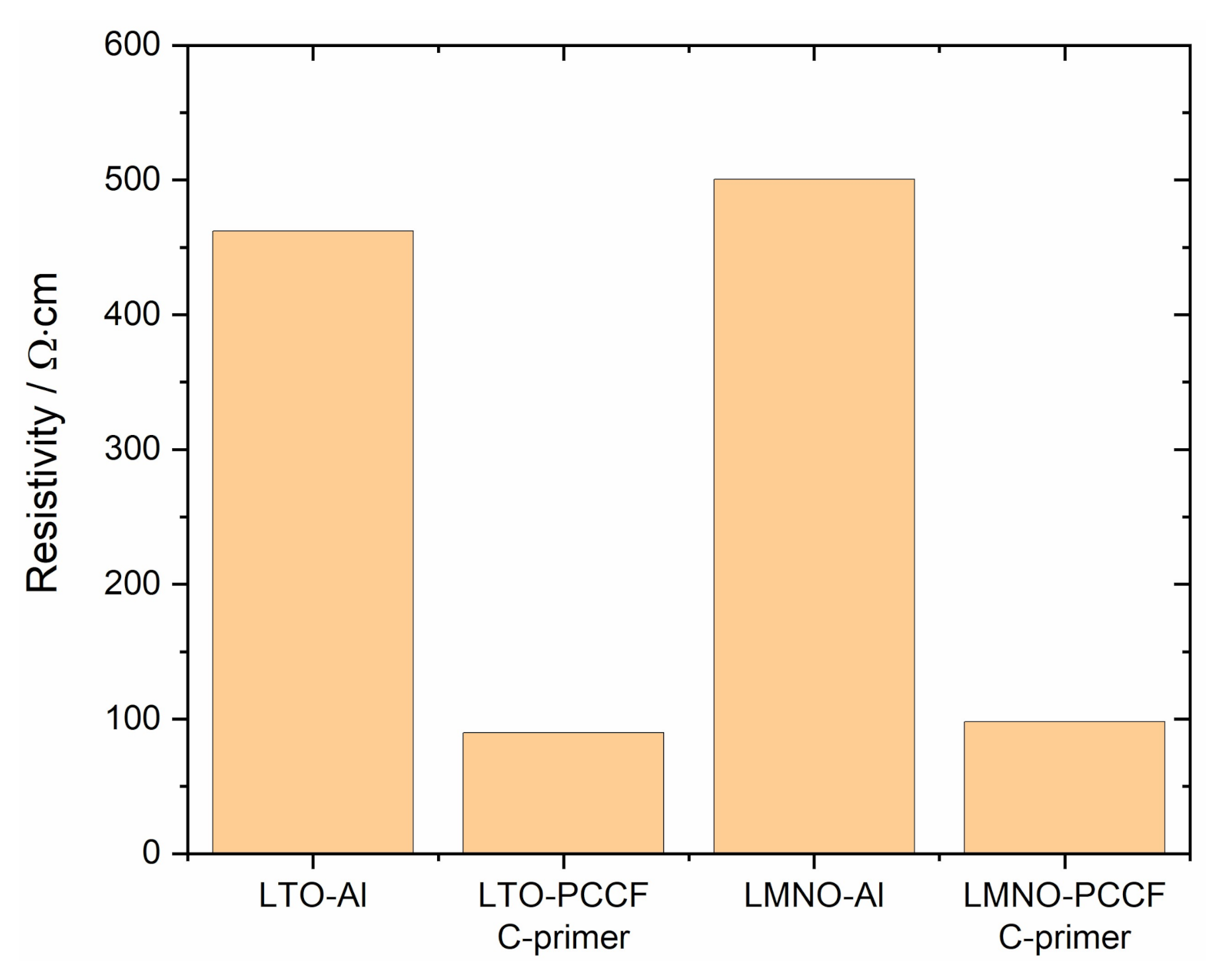
2.2.1. Electrical Properties and Advantage of Carbon Primer

Table 4 summarizes the electrical properties of the current collectors and prepared electrodes before the battery cell test.
The polymer composite shows low values of electrical resistivity of 0.7 Ω·cm in-plane parallel to the film extrusion direction. The resistivity in-plane perpendicular to the film extrusion direction was 2.7 Ω·cm. The resistivity measured through the film thickness, which is important for bipolar battery application, was 26 Ω·cm. As described in [22], carbon nanotubes are oriented mainly in in-plane direction due to their high aspect ratio. Therefore, the resistivity in-plane is much lower compared to through-plane. Especially for the MWCNTs used in this study it could be shown that the in-plane orientation in an extruded film is more pronounced than in a compressed molded plate. This is due to the melt flow and take-off forces during the film extrusion. In polymer composites filled solely with carbon black, only marginal anisotropy is determined due to the spherical shape of carbon black. No significant difference in CB orientation between pressed plate and extruded film was found. The quotient of in-plane and through-plane conductivity σ was calculated in [22] for the purpose of quantification of the different orientation degrees (see Table 5).
In the PCCF composite used in the present study with a mixed filler system, the advantages of both fillers can now be combined. Thus, for a composite with highly conductive CNTs, the formation of a conductive network can be expected even at a low CNT content. However, since this network develops primarily in-plane, the carbon black is supposed to form bridges between neighboring CNTs due to the low particle orientation and thus generates conductive paths through the plate (see Figure 1c). The higher in-plane conductivity compared to the through-plane values show that the formed conductive network is slightly more oriented in-plane even when using a mixed filler system. The importance of the CB for the conductivity through the plane (z) was described in Krause et al. [23]. The z-values of conductivity increase significantly with increasing addition of CB (1–4 wt.-%) to PVDF/1 wt.-% b-MWCNT. The quotients of electrical conductivities (Table 5, Table 2 in [23]) indicate that the addition of CB to CNTs leads to a significant lower orientation of the whole conductive network in the film. However, even after addition of CB, the orientation in the extrusion direction (x) is higher than that perpendicular to the extrusion direction (y), whereby the CB addition results in a slight decrease in σx/σy from 4 to 3.
The resistivity of the Al collector is several orders in magnitude lower compared to the PCCF, which is reasonable for a metal material (Table 4). Surprisingly, the through-thickness resistivity of LTO and LMNO electrodes on PCCF were by a factor of five lower compared to electrodes on Al collector (see comparison in Figure 5).
This was somewhat unexpected, since the measured resistivity of the bare PCCF was far higher compared to the Al collector. The measured electrode “through-thickness” resistance comprises a sum of collector bulk resistance, contact resistance between the coated films and electrode bulk resistance. The resistivity of the C-primer alone, prepared and measured as a bulk film, was determined to be 0.3 Ω·cm. This leads to the conclusion that the lateral in plane resistance on the surface of the C-primer coated PCCF-foil is rather low. The observed difference in electrical resistivity between electrodes based on Al or PCCF collector can be explained by a far lower contact resistance when using the developed C-primer in the case of PCCF collector. According to [28] the interfacial resistance accounts for a large portion of the whole impedance of an electrode without any treatments for the interfacial resistance reduction. One common procedure to reduce this interfacial resistance is the reduction of the electrode thickness by using a pressing technique, usually lamination or calander compression. However, this procedure leads to the reduction in pore size and volume, which causes the lithium-ion diffusivity resistance to increase [29,30]. Therefore, an optimized electrode porosity for most electrode material systems is around 35 vol.-% after densification, which is near to the 40 vol.% of the samples used in this study (see Table 3). Further, [28] demonstrated that a thin carbon under-coating layer, between the collector foil and the electrode film, can effectively decrease the impedance of the whole electrode. The microstructure of the electrodes on the Al collector in a cross section view (Figure 4a,b) shows, that at the interface between Al and electrode layer larger areas of “gaps”, with only limited and more isolated contact, are visible. On the other side, the interface region between C-primer film and electrodes on PCCF collector (Figure 4c,d) is much more cohesively and interlocked. The rather soft C-primer film should lead to a better compression behavior with the electrode microstructure during the lamination densification, which leads to an overall lower contact and electrode resistance, which is highly important for bipolar battery concepts. In state-of-the-art battery manufacturing with Al-foil collector calandering, instead of lamination technique, is normally used for electrode densification. Since some issues for PCCF during calandering were observed (crack formation due to foil thickness variation), a lamination technique was used in this work. The authors suspect, that lamination technique can be a proper densification method for bipolar battery electrodes and forming a battery stack of bipolar plates, since two different active materials will be coated on one collector foil. However, we admit that calandering could lead to better results for metal Al-foil collector, since it could benefit from deformation ability of Al-metal. Nevertheless, the observed difference in through-thickness resistance of this study is quite remarkable.

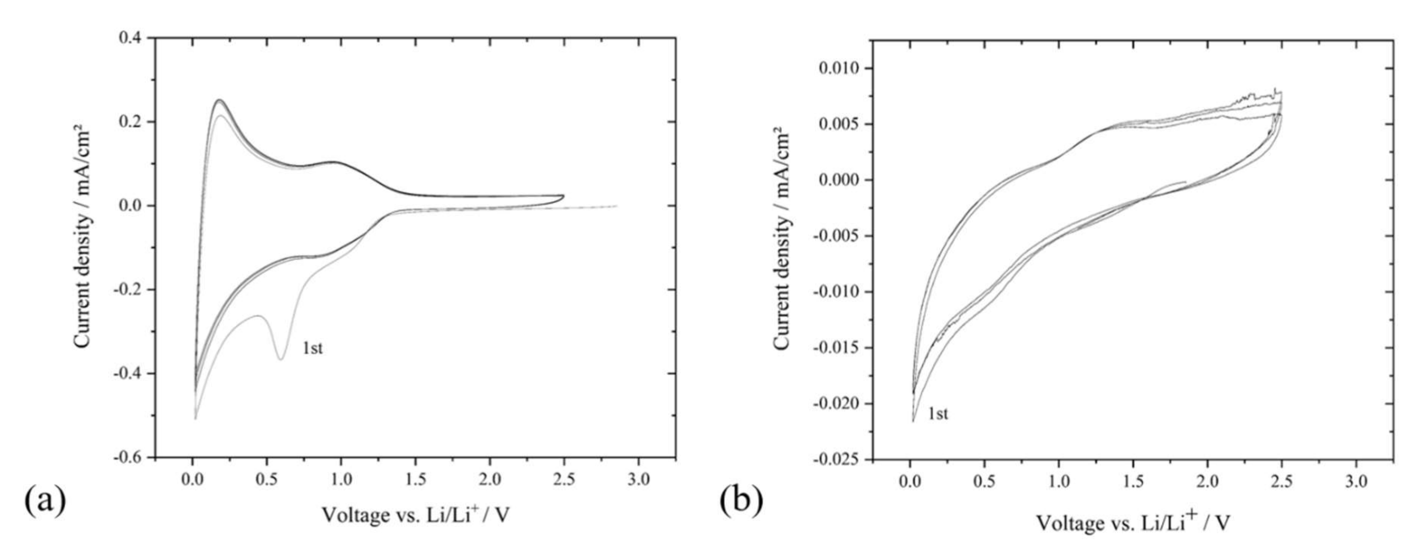
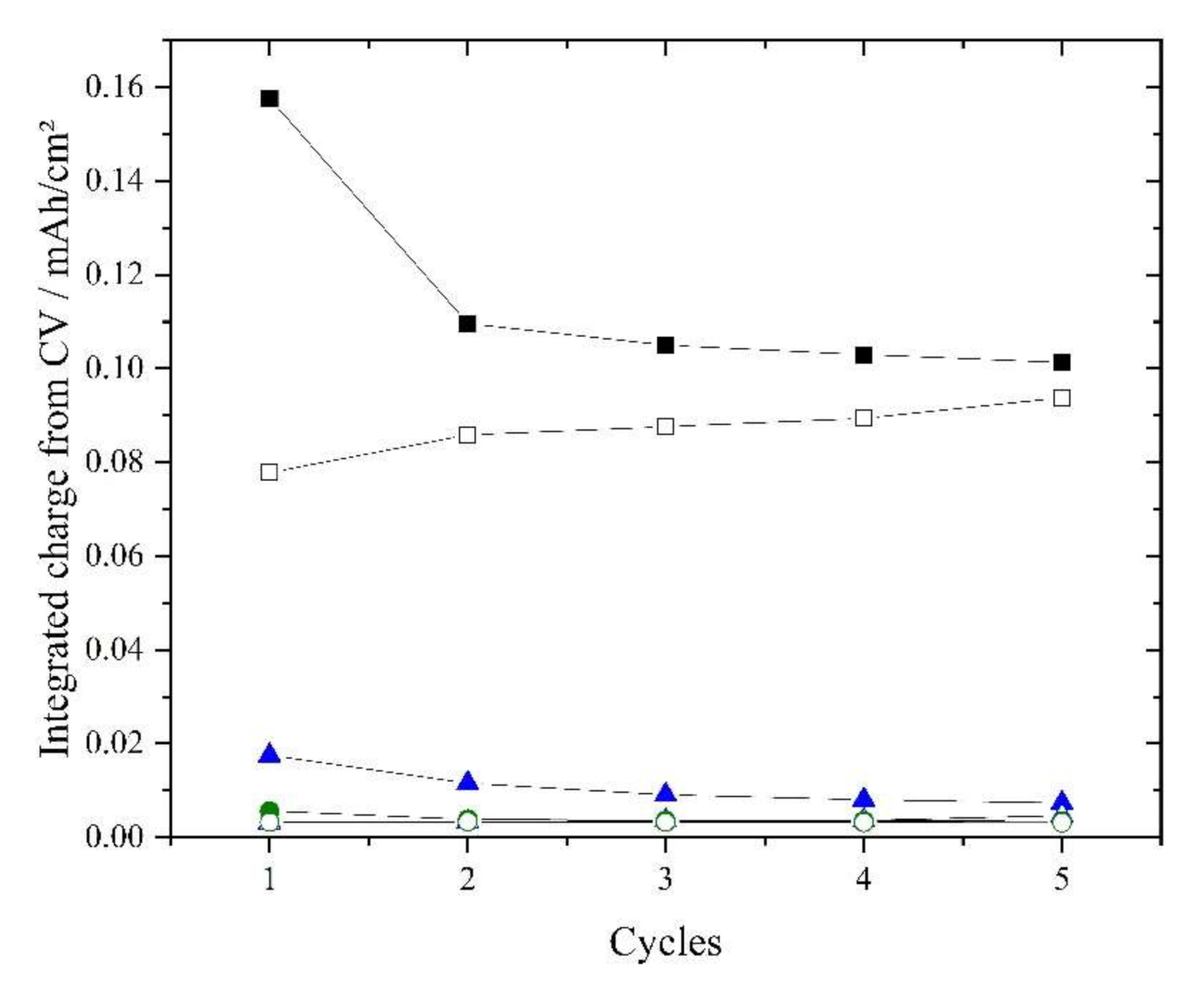
2.2.2. Electrochemical Stability of PCCF Collector between 0 V to 5 V

One important requirement for the use of current collector materials in lithium-ion batteries is their voltage stability in a wide range of potential window during battery cycling. In case of a cathode-anode combination like Lithium Nickel Manganese Cobalt Oxide (NMC) and graphite this is 3.0 to 4.3 V vs. Li/Li+ and in case of LMNO vs. graphite this is 3.0 to 5.0 V vs. Li/Li+. LSV and CV tests regarding reduction and oxidation stability were conducted to verify the electrochemical stability of PCCF collector. Figure 6a shows a LSV curve of the uncoated PCCF collector cycled versus metallic lithium.
The LSV curve in Figure 6a shows a near linear increase in current density up to 5.0 V vs. Li/Li+. The visible two slight humpbacks at 3.5 and 4.0 V seem not to have a great effect on the further trend. We conclude that such anomalies arise from a small capacitance charge at the PCCF and not from an electrochemical degradation reaction. Moreover the measured highest current density with 0.02 mA/cm2 is very low, underlining the fact that the PCCF is electrochemically stable up to 5.0 V vs. Li/Li+.The CV-curve in Figure 6b shows the current density of the PCCF collector cycled 10 times between 3.0 and 5.0 V vs. Li/Li+. The symmetrical shape of the curve indicates a capacity and no faradic reaction. The results demonstrate that the developed PCCF collector is compatible to the voltage range of NMC cathodes (approx. 4.3 V charging end potential) and also compatible to higher voltage materials like LMNO cathodes (5.0 V charging end potential), if long-term stable high-voltage liquid electrolytes are available.
Tests concerning the Li-ion intercalation into bare PCCF compared to C-primer coated PCCF collector were conducted to evaluate possible irreversible capacity losses due to Li-ion intercalation into carbon ingredients of PCCF (CNT-CB in PCCF as well as carbon black in C-primer layer).
In Figure 7a, the PCCF collector coated with C-primer shows two cathodic (reductive) peaks, which can be attributed to a solid electrolyte interface (SEI) formation (0.7 V) and a beginning of lithium intercalation (0 V). The first peak disappears after the first cycle, which supports the thesis for SEI formation. The following cycles show that the second peak slightly declines. The CV curve of PCCF collector without C-Primer (Figure 7b) shows a small intercalation peak at 0 V, but no affiliated de-intercalation peak. The comparison shows that the overall current density of the PCCF collector without C-primer coating is one order of magnitude lower (µA/cm2 range) than the C-primer coated PCCF (low mAh/cm2 range). It is suggested that a beginning of lithium intercalation into the C-Primer is visible, whereas the bare PCCF collector shows no intercalation behavior at all. To classify these observations, the CV-curves were integrated and the total amount of transported charge was calculated. Figure 8 shows these integrated negative and positive charge values from the oxidation and reduction parts of the CV curve.
For the PCCF collector with C-primer the charge values from reduction and oxidation tend to come close to each other after four cycles. A reversible intercalation and de-intercalation of 0.10 mAh/cm2 in each cycle was observed. The bare PCCF collector without C-primer shows charge values almost identical to a tested copper foil collector under identical conditions, with no intercalation effects. In summary we conclude that the C-primer coating is more dominant for a small Li-ion intercalation compared to the bare PCCF collector. The overall observed capacity losses due to Li-ion intercalation into C-primer are below 0.2 mAh/cm2. This is one magnitude lower compared to the area capacity of high energy (3–4 mAh/cm2) or high-power electrodes (0.5–1.5 mAh/cm2). A reduction of this effect can be expected by reducing the C-primer film thickness. Further, if an optimization of the surface microstructure of the PCCF could make the use of C-primer obsolete, it will avoid the observed capacity loss.

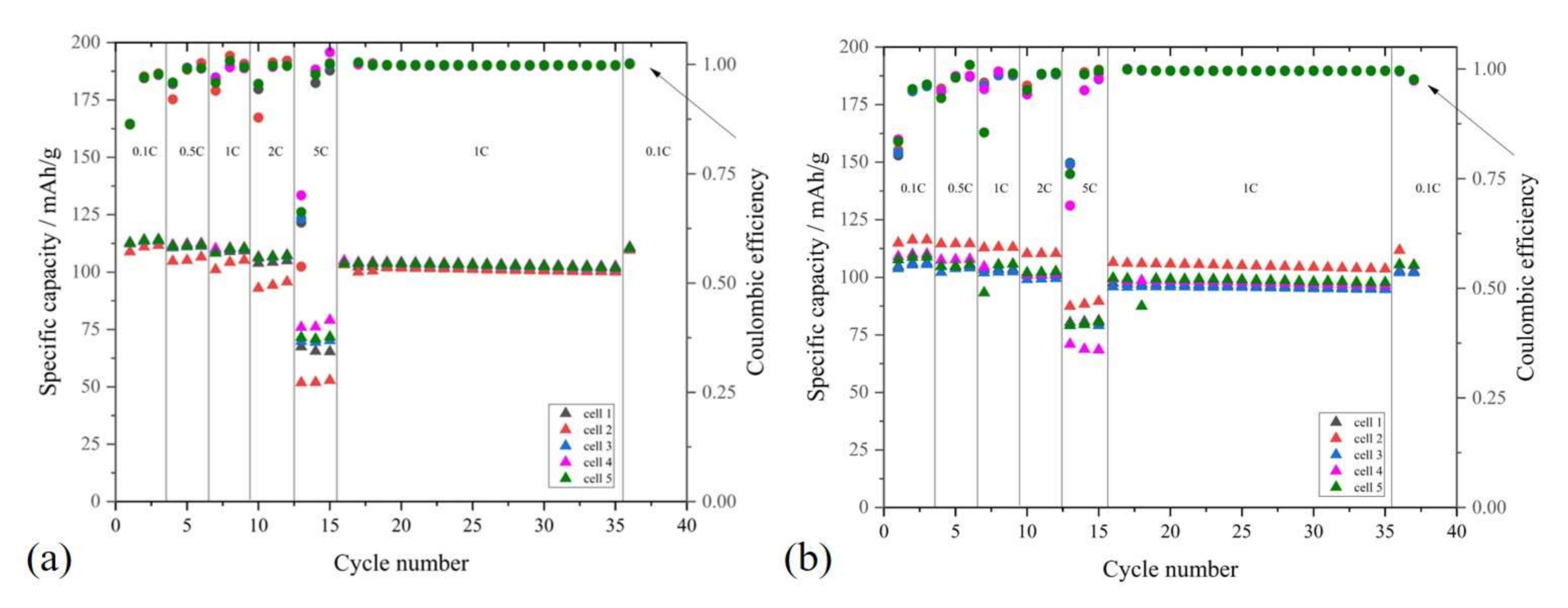
2.2.3. C-Rate Performance Test of LMNO and LTO on Al and PCCF Collector

In order to validate the functionality of the developed PCCF collector as an alternative current collector for Al foil, cycling tests with LMNO and LTO electrodes in monopolar half-cell configuration were conducted with performance tests from 0.1 to 5 C.
Figure 9 shows the cycling performance and of LTO on Al collector in comparison to LTO on PCCF-C-primer collector. The electrodes on Al collector show a reproducible capacity ranging from 167 mAh/g (0.1 C), 162 mAh/g (1 C) and 139 mAh/g (5 C) for higher C-rates. The cells with LTO on PCCF collector show 159 to 166 mAh/g (0.1 C), 153 to 164 mAh/g (1 C) and 108–127 mAh/g (5 C, with a slight decreasing trend). The coulombic efficiency in both tests, LTO on aluminum as well as LTO on PCCF, show high values above 0.99, which illustrates that no major side reaction is occurring. Single efficiency drops in both experiments, after changing to a 5 C cycle rate, are visible, which are attributed to mathematical artefacts from the efficiency calculation. During a constant 1 C cycling the coulombic efficiency stays constantly above 0.99. We observed that capacity values from the LTO electrodes on PCCF collector scatter more compared to Al collector. The reason is a larger deviation of the calculated electrode weight in the individual test cells, since the thickness of the prepared PCCF collector with nominal 70 µm thickness shows a higher thickness tolerance compared to the industrial 19 µm thick Al collector. This includes a possible thickness variation of 2 to 5 µm of the C-primer coating on PCCF. In sum, these deviations due to laboratory preparation methods will add up and lead to a slight variation of the calculated LTO mass, which was used to derive the collector cell capacities. It can be assumed, that by using scaled industrial manufacturing machines such deviations in collector thickness precision will be limited. The results demonstrate, that LTO electrodes on PCCF collector show comparable cell performance compared to electrodes on Al collector.
Figure 10 shows the cycling performance test of LMNO on Al collector in comparison to PCCF-C-primer collector. The electrodes on Al collector show capacity values of 114 mAh/g (0.1 C), 103 mAh/g (1 C) and 52 to 78 mAh/g (5 C). The cells of LMNO on PCCF collector show 103 to 116 mAh/g (0.1 C), 95 to 106 mAh/g (1 C) and 67 to 90 mAh/g (5 C). The prepared LMNO test cells show a scattering of capacities by a given C-rate and a capacity decline within 20 cycles at 1 C, independently of collector type. Since a non-commercial, self-developed LMNO active material was used in this study, we attribute the capacity fade to the degradation of the active material [31]. The coulombic efficiency in the beginning of each cycle after changing the C-rate shows noticeably scattering values, which are attributed to artefacts from the mathematical efficiency calculation. Additionally, we did not observe any differences in the voltage curves from the cycling experiments, between electrodes on Al collector or PCCF. This underlines the fact that the PCCF is equivalent to an Al collector in terms of the here tested cycling behavior of the electrodes. The detailed voltage profiles of one coin cell out of five from the measurements in Figure 9 and Figure 10 are shown in Figure S1 (in supplementary). For further development we propose long-term cycling studies to exclude effects, which might occur after many cycles and were out of scope for this work.
Table 6 summarizes the cell capacities at 0.1 C before and after a 20-cycle test at 1 C. The capacities as well as the cell resistance of the prepared samples are comparable between Al collector and PCCF collector. The observed lower electrode resistances for PCCF collector sheet samples (Table 4) has no visible influence on the overall cell resistance compared to Al collector, since the proportion to the total cell resistance is low (single digits of Ohms). The post-mortem disassembled cells show no visible degradation of the PCCF collector (Figures S2 and S3 in Supplementary).
Further, the observed capacity losses due to intercalation effects into the C-primer of PCCF collector (Figure 8) seem to be so small, that they show no visible influence on the overall cell capacities, which are several orders in magnitudes higher. Even possible electrochemical side reactions at high voltage of 5 V (see LSV test in Figure 6) seem to have no pronounced effect on the cycling performance of LMNO on PCCF collector.
The results show that the developed PCCF collector fulfills the electrochemical requirements to be used as an alternative current collector for lithium-ion batteries.

2.3. Discussion of PCCF as an Alternative Current Collector for Li-Ion Batteries

Table 7 compares the mass loading between standard Al and Cu collector and the developed PCCF polymer collector. The bulk density of the PCCF-C-primer collector is 1.4 g/cm3 and 44 to 48% lower in comparison to state-of-the-art Al foil with 2.5 to 2.7 g/cm3 and 84% lower compared to Cu foil with 8.9 g/cm3. However, due to a much lower Cu- and Al-foil thickness, the mass loading is higher for the PCCF collector manufactured in our laboratory. It can be assumed that progress in the manufacturing technology of such polymer collectors can lead to PCCF thicknesses in the range of 25 to 40 µm, which will decrease the mass loading of the collector to approx. 24% below Al foil. Further, if one day PCCF collectors with optimized surfaces without additional carbon primer coating are available, a potential saving in mass loading of 36% compared to state-of-the-art Al collector is possible. Compared to Cu foil, the developed PCCF of this study is comparable in mass loading and a PCCF optimization will lead to an even greater potential for mass saving compared to Al foil.
Concerning material costs for both current collector types, a rough estimation can be done based on prices for laboratory scale developments: Purchasing prices of Al-foil of 26.85 EUR/kg, Cu-foil of 66.74 EUR/kg and raw materials costs of PCCF collector with PVDF polymer powder and carbon additives of 42.20 EUR/kg and approx. 80 EUR/kg for processing of PCCF due to composite compounding and film extrusion steps (5 kg batch). Table 8 shows, that the developed PCCF polymer collector exceeds the price of a commercial Al-foil by a factor of 9 and compared to Cu-foil by a factor of 2. However, since only small-scale laboratory consumables and equipment were used in this study, it can be expected, that by industrial scaling the raw material prices, compounding and extrusion costs as well as the PCCF thickness can be significantly reduced (38 EUR/kg and 25 µm thickness) to achieve a comparable and competitive price competitive with Al-and Cu-foil.
In comparison to metal collectors, the developed PCCF collector is compatible to a large variety of anode and cathode materials due to his wide potential range stability (0 to ~5 V vs. Li/Li+). Further, since the PCCF is hermetically dense, it is suitable to be used in bipolar battery architectures, where alternative bimetal or carbon based collectors are usually facing issues of residual porosity and the possibility of internal battery short circuits [7,19]. One concern of using our developed PCCF collector is the ecologically impact for scaling to mass production. Regarding recycling of battery cell components, polyvinylidene fluoride (PVDF) normally decomposes during thermal treatment in volatile hydrogen fluoride, which can cause equipment corrosion and creates a potential environmental hazard. But recent studies indicate that the use of CaO as a reaction medium can avoid the release of hydrogen fluoride and reduce the processing costs during recycling [33]. Estimates about energy consumption of PCCF vs. Al collector for battery cell manufacturing are hard to assess. In state-of-the-art 10 Ah NMC cells, the Al cathode collector weights 6 to 16 times more than the PVDF binder in the cathode, depending if the cell is energy or power optimized. Another study regarding the energy consumption of Li-ion battery materials and production process [34], gives the information that the proportionally ratio in energy consumption for NMC-cathodes between Al (collector) and PVDF (binder for cathode) is 10 to 1 [35]. Based on these assumptions, we suppose that energy consumption for manufacturing of battery cells, where traditional Al collector is replaced by the developed PCCF collector (consists mainly of PVDF polymer), will be comparable.

3. Materials and Methods

3.1. Polymer-Carbon Collector Foil (PCCF)

A commercially available poly (vinylidene fluoride) (PVDF) was applied, namely Kynar720 (Arkema, Colombes Cedex, France) with a melt flow index of 5–29 g/10 min at 5.0 kg loading (230 °C). As the electrically conductive fillers, mixtures of branched multi-walled carbon nanotubes (b-MWCNTs) and carbon black (CB) were chosen. The b-MWCNT “CNS flakes” (Applied NanoStructured Solutions LLC, Baltimore, MD, USA) are coated with 3 wt.-% poly (ethylene)glycol and have a diameter of 14 ± 4 nm and length of ~70 µm (aspect ratio ~5000) [22]. The CB is a highly structured type of Ketjenblack EC600JD (Akzonobel, Cologne, Germany) with a BET surface area value of 1200 m2/g and a primary particle size d50 of 34 nm (according to the supplier). For the polymer-carbon composite a combination of 1.0 wt.-% b-MWCNT with 3 wt.-% CB was used to achieve an optimized electrical conductivity.
Compounding was done via melt mixing by using a laboratory twin-screw extruder ZE 25 (KraussMaffei Berstorff GmbH, Hannover, Germany) with a screw with L/D ratio of 48. The pre-mixed PVDF powder with both carbon-fillers was compounded at a temperature of 210–230 °C, a rotation speed of 200 rpm and a throughput of 5 kg/h. For homogenization, the composite was extruded again under the same conditions. The extruded strands were granulated into approx. 2 mm diameter pellets. Cast film extrusion was performed with these composite granules using a 30 mm single-screw extruder (DAVO GmbH & Co. Polyrema KG, Troisdorf, Germany) in combination with a cast film line (Dr. Collin GmbH, Maitenbeth, Germany). The width of the flat die was 30 cm, the gap width was set to 100 µm, and the mass temperature was 290 °C. The take-off velocity was set to 3.7 m/min. Rolls of polymer-carbon collector foil (PCCF) with a width of 22 cm, a thickness of 55 µm and lengths of 50 m were achieved.

3.2. LMNO, LTO and C-Primer Electrode Coatings

LiNi0.5Mn1.5O4 (LMNO) powder (PU110, synthesized by Fraunhofer IKTS described elsewhere [31]) and Li4Ti5O12 (LTO) powder (HOMBITEC® LTO5, Huntsman Pigments and Additives, Duisburg, Germany) were used along with carbon black (SUPER P® Li, Imerys Graphite & Carbon, Bironico, Switzerland) and water-based polyacrylate (PAA) cathode binder BA-310C or anode binder BA-210S (15 wt.-% polymer solid content, both from Fujian Blue Ocean & Black Stone Techn. Co LTD, Zhangzhou, China). For the carbon primer, the BA-210S binder was used. Coatings were applied on Al foil (Li-ion battery grade, EN AW 1085-L H18, Hydro Aluminum Rolled Products GmbH [24]) or PCCF (see 3.3.1) as current collectors. Prior to coating both current collector samples were cut to 12 × 12 cm2 size.
For preparation of the carbon primer (C-primer) BA-210S binder was mixed with carbon black powder in deionized water with a dissolver (Dispermat LC, VMA Getzmann, Reichshof, Germany) up to a powder solid content of 6.2 wt.-%. The ratio of carbon black/BA-210S was set to 68.4/31.6 wt.-%. The slurry showed a viscosity of 4.0 Pas at a shear rate of 20 s−1 at 20 °C. PCCF collector was coated on both sides by a manual film applicator (Model 360, ERICHSEN GmbH & Co. KG, Hemer, Germany) with 120 µm blade gap and 90 mm coating width. In between both coating steps, a drying step at 60 °C for 24 h was set.
For the LMNO slurry, carbon black was first dispersed by a dissolver (Dispermat LC, VMA Getzmann, Germany) in BA-310C and additional deionized water (powder solid content of 2.8 wt.-%) followed by mixing with LMNO powder up to a powder solid content of 30.5 wt.-%. The quantity ratio of LMNO/carbon black/BA-310C binder was set to 85/6/9 wt.-%. The LMNO slurry pH was 6.2 and viscosity of 0.9 Pas at a shear rate of 20 s−1 at 20 °C. For the LTO slurry, carbon black was first dispersed by dissolver in BA-210S and additional deionized water (powder solid content of 3.0 wt.-%) followed by mixing with LTO powder up to a powder solid content of 31.6 wt.-%. The quantity ratio of LTO/carbon black/BA-210S binder was set to 85/6/9 wt.-%. The LTO slurry pH was 8.3 and viscosity of 5.4 Pas at a shear rate of 20 s−1 at 20 °C. Both LMNO and LTO slurries were casted on Al-foil and C-primer pre-coated PCCF collector by a manual doctor blade film applicator (LBT304 from Jokob Weiß & Söhne, Sinsheim, Germay) with 400 µm blade gap. The films were dried at 60 °C in a laboratory drying cabinet for 24 h. After drying, half of the electrodes were densified by pressing in an isostatic laminator at 250 bar, 70 °C for 10 min (IL-4012PC from Pacific Trinetics Corp, Fremont, USA).

3.3. Material Characterization

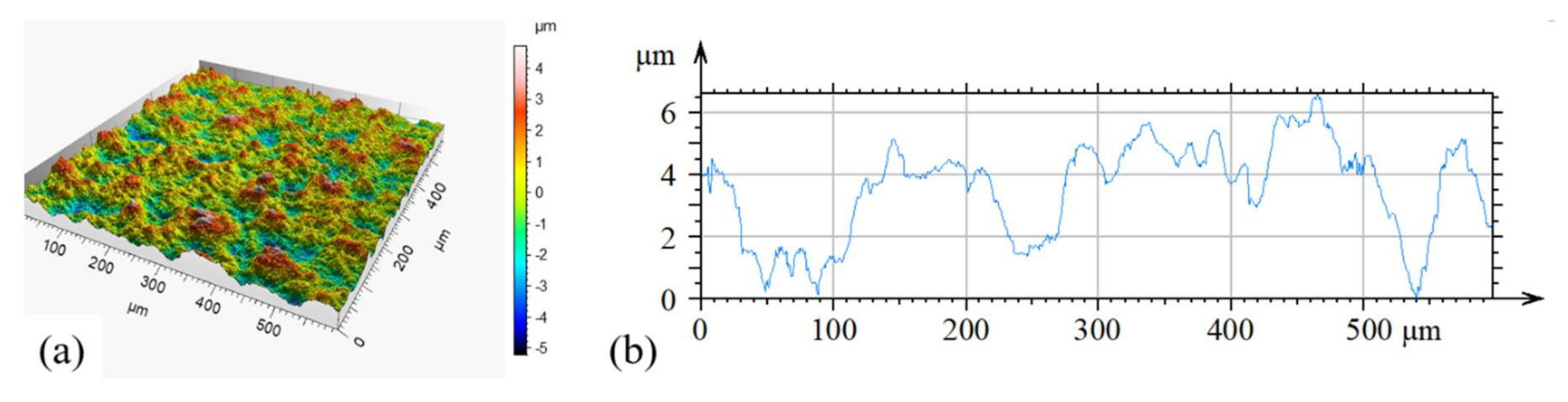
3.3.1. Polymer-Carbon Collector Foil (PCCF)

Tensile tests for determination of mechanical properties were performed with a tensile universal testing machine Z010 (ZwickRoell, Ulm, Germany) based on cut stripes of PCCF (length 115 mm, width 10 mm) with foil extrusion direction perpendicular or in extrusion direction and a displacement rate of 5 mm/min (according to DIN 53504/1A/5). The roughness and topography of the PCCF was investigated using a confocal 3D microscope µsurf (Nanofocus, Oberhausen, Germany), which derives a 3D image and the height profile. The characterization of filler dispersion in the PVDF composite by scanning electron microscopy (SEM) was performed on the foil surface using a Zeiss Ultra Plus microscope (Carl Zeiss AG, Oberkochen, Germany) in charge contrast imaging mode (CCI). To characterize the gas-tightness of the PCCF, a gas leak detector (air and helium) with PCCF sample size of 5 × 5 cm2 was used (PhoenixL300 Leybold GmbH, Collogne, Germany).

3.3.2. Electrode Coatings

The collector foils and the prepared electrodes were characterized regarding thickness and weight using a mechanical thickness gauge for films and paper and a precision balance. Based on the measured thickness (D in µm), weight (in mg) and sample area size (in cm2), values for area weight (AW = mass/area in mg/cm2) and density (ρ = AW·10/D in g/cm3) were calculated for current collectors and electrode coated samples. By subtraction of thickness and area weight of the current collector from the electrode coated samples, specific parameters (D, AW) were derived explicitly for the electrode film. By comparison of the electrode film density (ρfilm in g/cm3) with the theoretical density of the electrode raw materials (sum of active material, carbon black and binder: ρfilm,th in g/cm3) the electrode film porosity was estimated ((1-ρfilm,thfilm)·100 in vol.%). The electrode cross-section, prepared by ion polishing was characterized by SEM (Crossbeam NVISION 40, Carl Zeiss SMT, Oberkochen, Germany).

3.3.3. Electrical Measurements

The electrical resistance of the PCCF collector in-plane was measured by a 4-point measurement using an device developed by the authors (see detailed description of this method in [22]). Therefore, PCCF samples of 30 by 25 mm size where metallized on the sample surfaces by a thin film of silver paste to reduce the contact resistance during measurement.
To evaluate electrical performances of electrodes coated on the PCCF foil two-point through plane resistance measurements were carried out. For this, electrode samples of 4 × 4 cm2 size were clamped between two copper plungers with a graphite fleece in between. The plungers were pressed with a force of 402 N (equals to 2.5 bar) against each other, measured by a force measuring sensor. A constant voltage of 10.0 V was used to supply the force sensor and the output voltage was measured with a Keithley 2700 multimeter. The resistance was measured with a milliohmmeter (HP 4338A). The resistance is internally calculated by applying a 1 kHz alternating current, and the sample impedance at 1 kHz was measured, which is in that case equal to the ohmic resistance. Values of uncoated as well as with electrodes coated PCCF current collectors were compared.
To characterize the film resistance of the thin C-primer, reference specimens of 40 µm thick and laminated C-primer films were prepared on ceramic substrates by using the carbon primer slurry and a manual film applicator (procedure is described elsewhere [36]).

3.4. Electrochemical Characterization

The PCCF current collector as well as the prepared LMNO and LTO electrodes on Al-foil and PCCF were electrochemically tested in cycling charge-discharge and cyclic voltammetry experiments by using a coin cell setup. The assembly was conducted in an argon filled glove box with an atmosphere of O2 < 2 ppm and H2O < 2 ppm. All materials used for this assembly, as well as the electrodes were pre-dried in a vacuum oven at 105 °C at 40 mbar for 24 hrs to ensure a complete removal of water residues. Lithium chips of thickness 300 µm (Xiamen Tob New Energy Technology, Xiamen, China) were used as a counter electrode and 150 µL of the electrolyte LP40 (BASF, Ludwigshafen, Germany) was soaked into two separators (FS3002-23, Freudenberg Performance Materials Holding SE & Co. KG, Weinheim, Germany). The assembly of the coin cell was carried out with a crimp machine (MT-160D, MTI Corp., Richmont, CA, USA). All electrode samples used for cyclic voltammetry (CV) were assembled into El-Cell test cells (ECC-Standard, El-Cell GmbH, Hamburg, Germany) under the same conditions as the coin cells in the glove box. In CV tests, the PCCF-foil was measured against metallic lithium with a LP 40 soaked separator (Freudenberg). CV experiments were carried out by a potentiostat (VMP3, BioLogic, Seyssinet-Pariset, France) in a climate chamber at 30 °C. Charge and discharge cycling experiments were conducted with a Basytec CTS potentiostat (Basytec GmbH, Asselfingen, Germany) in the same climate chambers (CTS T-40/50, CTS GmbH, Hechingen, Germany) at 30 °C. LMNO electrodes were cycled between 5.0 and 3.5 V vs. Li/Li+ and LTO electrodes were cycled between 2.5 V and 1.0 V vs. Li/Li+ in coin cells. For the charge and discharge experiments, 5 identical coin cells were manufactured and measured simultaneously (referenced as cell 1–5 in each experiment), adding up to 20 coin cells. To evaluate a possible degradation of PCCF collector after cell cycling, a post-mortem analysis was done by disassembling of test cells and visual inspection.

4. Conclusions

A polymer-carbon composite current collector foil (PCCF) for bipolar lithium-ion battery applications is developed and evaluated in comparison to state-of-the-art Al-foil collector. The PCCF shows sufficient mechanical properties, which allow the processing of the PCCF collector in a roll-to-roll industrial electrode coater. The PCCF proved to be hermetical dense, which is important to avoid liquid electrolyte penetration through the collector. The applicability for lithium-ion batteries was studied based on water-processed LiNi0.5Mn1.5O4 (LMNO) cathode and Li4Ti5O12 (LTO) anode coatings with the integration of a thin carbon primer at the interface to the collector. Despite the fact that the laboratory-manufactured PCCF shows a much higher film thickness of 70 µm compared to Al-foil of 19 µm, the electrode resistance was measured to be by a factor of five lower compared to Al collector, which was attributed to the low contact resistance between PCCF, carbon primer and electrode microstructure. The PCCF-C-primer collector shows a sufficient voltage stability up to 5 V vs. Li/Li+ and low Li-intercalation losses into the carbon primer of the PCCF (~0.1 mAh/cm2), which makes him compatible to a wide range of anode and cathode active materials. Electrochemical cell tests demonstrate the applicability of the developed PCCF for LMNO and LTO electrodes, with no obvious disadvantage compared to Al collector. The advantage of a nearly 50% lower raw material density of the PCCF polymer collector compared to metal Al-foil along with expected improvements in collector thickness reduction and cost savings, due to a scaled industry manufacturing approach, will offer the possibility to significantly reduce the mass loading of the collector in the battery cell. Overall, the developed PCCF collector appears to be advantageous, especially for bipolar battery architectures, where a combination of the abovementioned properties is needed which cannot be fulfilled by today´s metal-, bimetal- or carbon-based collectors.

Supplementary Materials

The following are available online at https://0-www-mdpi-com.brum.beds.ac.uk/2313-0105/6/4/60/s1, Figure S1: Voltage profiles of measured coin cells from Figure 9 and Figure 10 (first three cycles at 0.1 C); Top left: LTO on PCCF, Top right LTO on Al-collector, Bottom left: LMNO on PCCF, Bottom right: LMNO on Al, Figure S2: Post-mortem picture of PCCF-foil of a LTO cell after cycling test according to Figure 9; Left: PCCF C-primer side in contact to LTO electrode after cycling, Right: Backside of the PCCF after cycling of LTO in coin cell, Figure S3: Post-mortem picture of PCCF-foil of a LMNO cell after cycling test according to Figure 10; Left: PCCF C-primer side in contact with LMNO electrode coating (some separator residue white) after cycling on coin cell; Right: Backside of the PCCF after cycling of LMNO in coin cell.

Author Contributions

Conceptualization, M.F. and M.C.; methodology, M.F., M.C., B.K., P.P.; validation, M.F. and M.C.; investigation, M.F., M.C., P.M., B.K.; writing—original draft preparation, M.F., M.C., K.K., B.K. and P.P.; writing—review and editing, M.F.; visualization, M.F., M.C., B.K. and P.P.; supervision, M.W. and A.M.; project administration, M.W. All authors have read and agreed to the published version of the manuscript.

Funding

This research was funded by German Federal Ministry of Education and Research (BMBF) project EMBATT2.0 No. 03XP0068G and No. 03XP0068E.

Acknowledgments

The authors thank the processing laboratory of IPF, headed by I. Kühnert, and especially F. Pursche for carrying out the melt compounding and film extrusion experiments. We thank O. Kobsch (IPF) for performing roughness measurements and S. Höhn (IKTS, Ceramography and Phase Analysis) for sample preparation and SEM analysis.

Conflicts of Interest

The authors declare no conflict of interest.

References

  1. Marsha, R.A.; Russell, P.G.; Reddy, T.B. Bipolar lithium-ion battery development. J. Power Sources 1997, 65, 133–141. [Google Scholar] [CrossRef]
  2. Jung, K.; Shin, H.; Park, M. Solid-State Lithium Batteries: Bipolar Design, Fabrication and Electrochemistry. ChemElectroChem 2019, 6, 3842–3859. [Google Scholar] [CrossRef]
  3. Iwakura, C.; Fukumoto, Y.; Inoue, H.; Ohashi, S.; Kobayashi, S.; Tada, H.; Abe, M. Electrochemical characterization of various metal collectors as a current collector of positive electrode for rechargeable lithium batteries. J. Power Sources 1997, 68, 301–303. [Google Scholar] [CrossRef]
  4. Whitehead, A.H.; Schreiber, M. Current Collectors for Positive Electrodes of Lithium-Based Batteries. J. Electrochem. Soc. 2005, 152, A2105–A2113. [Google Scholar] [CrossRef]
  5. Myung, S.-T.; Hitoshi, Y.; Sun, Y.-K. Electrochemical behavior and passivation of current collectors in lithium-ion batteries. J. Mater. Chem. 2011, 21, 9891–9911. [Google Scholar] [CrossRef]
  6. Stich, M.; Fritz, M.; Roscher, M.; Peipmann, R. Korrosionsverhalten von bipolaren Stromableitern für Lithium-Ionen-Batterien (Teil 1). Galvanotechnik 2018, 12, 2330–2336. [Google Scholar]
  7. Stich, M.; Fritz, M.; Roscher, M.; Peipmann, R. Korrosionsverhalten von bipolaren Stromableitern für Lithium-Ionen-Batterien (Teil 2). Galvanotechnik 2019, 1, 67–72. [Google Scholar]
  8. Beikai, Z. The Height that a Kind of Bipolar Template Transitionality Unit Lithium Battery of Cu-Al Bimetal and Its Series Connection Are Formed Forces down Changeable Internal Damp Battery Heap and Method for Packing. China Patent 104916864B, 16 January 2018. [Google Scholar]
  9. Culver, D.; Dyer, C.K.; Epstein, M.L. Modular Battery with Battery Cell Having Bimetallic End. U.S. Patent 20110200867, 18 August 2011. [Google Scholar]
  10. Hossain, S. Bipolar Lithium-Ion Rechargeable Battery. U.S. Patent 5595839, 21 January 1997. [Google Scholar]
  11. Braunovic, M.; Aleksandrov, N. Effect of electrical current on the morphology and kinetics of formation of intermetallic phases in bimetallic aluminum-copper joints. In Proceedings of the IEEE Holm Conference on Electrical Contacts, Pittsburgh, PA, USA, 27–29 September 1993; pp. 261–268. [Google Scholar] [CrossRef]
  12. Silveria, V.L.A.; Mury, A.G. Analysis of the behavior of bimetallic joints (Al /Cu). J. Microstruct. Sci. 1987, 14, 277–287. [Google Scholar]
  13. Abbasi, M.; Taheri, A.K.; Salehi, M.T. Growth rate of intermetallic compounds in Al/Cu bimetal produced by cold roll welding process. J. Alloy. Compd. 2001, 319, 233–241. [Google Scholar] [CrossRef]
  14. Fritsch, M.; Standke, G.; Heubner, C.; Langklotz, U.; Michaelis, A. 3D-cathode design with foam-like aluminum current collector for high energy density lithium-ion batteries. J. Energy Storage 2018, 16, 125–132. [Google Scholar] [CrossRef]
  15. Li, S. Corrosion of Aluminum Current Collector in Cost Effective Rechargeable Lithium-Ion Batteries. Dissertation, No.1384, University of Wisconsin-Milwaukee, USA. 2016. Available online: https://dc.uwm.edu/etd/1384 (accessed on 4 December 2020).
  16. Ma, T.; Xu, G.-L.; Li, Y.; Wang, L.; He, X.; Zheng, J.; Liu, J.; Engelhard, M.H.; Zapol, P.; Curtiss, L.A.; et al. Revisiting the Corrosion of the Aluminum Current Collector in Lithium-Ion Batteries. J. Phys. Chem. Lett. 2017, 8, 1072–1077. [Google Scholar] [CrossRef] [PubMed]
  17. Kim, W.S.; Cho, K.Y. Current Collectors for Flexible Lithium Ion Batteries: A Review of Materials. J. Electrochem. Sci. Technol. 2015, 6, 1–6. [Google Scholar] [CrossRef]
  18. Foreman, E.; Zakri, W.; Sanatimoghaddam, M.H.; Modjtahedi, A.; Pathak, S.; Kashkooli, A.G.; Garafolo, N.G.; Farhad, S. A Review of Inactive Materials and Components of Flexible Lithium-Ion Batteries. Adv. Sustain. Syst. 2017, 1, 1700061. [Google Scholar] [CrossRef]
  19. Wang, K.; Wu, Y.; Wu, H.; Luo, Y.; Wang, D.; Jiang, K.; Li, Q.; Li, Y.; Fan, S.; Wang, J. Super-aligned carbon nanotube films with a thin metal coating as highly conductive and ultralight current collectors for lithium-ion batteries. J. Power Sources 2017, 351, 160–168. [Google Scholar] [CrossRef]
  20. Evanko, B.; Yoo, S.J.; Lipton, J.; Chun, S.-E.; Moskovits, M.; Ji, X.; Boettcher, S.W.; Stucky, G.D. Stackable bipolar pouch cells with corrosion resistant current collectors enable high-power aqueous electrochemical energy storage. Energy Environ. Sci. 2018, 11, 2865–2875. [Google Scholar] [CrossRef]
  21. Krause, B.; Barbier, C.; Kunz, K.; Pötschke, P. Comparative study of singlewalled, multiwalled, and branched carbon nanotubes melt mixed in different thermoplastic matrices. Polymer 2018, 159, 75–85. [Google Scholar] [CrossRef]
  22. Kunz, K.; Krause, B.; Kretzschmar, B.; Juhasz, L.; Kobsch, O.; Jenschke, W.; Ulrich, M.; Pötschke, P. Direction dependent electrical conductivity of polymer/carbon filler composites. Polymers 2019, 11, 591. [Google Scholar] [CrossRef] [Green Version]
  23. Krause, B.; Kunz, K.; Kretzschmar, B.; Kühnert, I.; Pötschke, P. Effect of filler synergy and cast film extrusion parameters on extrudability and direction-dependent conductivity of PVDF/carbon nanotube/carbon black composites. Polymers 2020. Submitted for publication. [Google Scholar]
  24. Hampel, U.; Denkmann, V.; Siemen, A.; Eckhard, K.; Schenkel, W.; Eberhard, S.; Bögershausen, D. Chemically Treated Current Collector Foil Made of Aluminium or an Aluminium Alloy. U.S. Patent 9160006B2, 13 October 2015. [Google Scholar]
  25. Kunz, K.; de Limé, A.d.B.; Seeba, J.; Reuber, S.; Wolter, M.; Michaelis, A. Possibilities for Processing of All Solid State Batteries/Components as Pilot Plant Scale. Poster, Dresden Battery Days, 23–25 September 2019. Available online: https://www.energy-saxony.net/veranstaltungen/dresden-battery-days-23-25092019.html (accessed on 4 December 2020).
  26. Sacher, E. (Ed.) Metallization of Polymers 2; Springer: Boston, MA, USA, 2002; ISBN 978-1-4615-0563-1. [Google Scholar] [CrossRef]
  27. Nakanishi, S.; Suzuki, T.; Cui, Q.; Akikusa, J.; Nakamura, K. Effect of surface treatment for aluminum foils on discharge properties of lithium-ion battery. Trans. Nonferr. Met. Soc. China 2014, 24, 2314–2319. [Google Scholar] [CrossRef]
  28. Nara, H.; Mukoyama, D.; Shimizu, R.; Momma, T.; Osaka, T. Systematic analysis of interfacial resistance between the cathode layer and the current collector in lithium-ion batteries by electrochemical impedance spectroscopy. J. Power Sources 2019, 409, 139–147. [Google Scholar] [CrossRef]
  29. Heubner, C.; Nickol, A.; Seeba, J.; Reuber, S.; Junker, N.; Wolter, M.; Schneider, M.; Michaelis, A. Understanding thickness and porosity effects on the electrochemical performance of LiNi0.6Co0.2Mn0.2O2-based cathodes for high energy Li-ion batteries. J. Power Sources 2019, 419, 119–126. [Google Scholar] [CrossRef]
  30. Heubner, C.; Schneider, M.; Michaelis, A. Diffusion-Limited C-Rate: A Fundamental Principle Quantifying the Intrinsic Limits of Li-Ion Batteries. Adv. Energy Mater. 2020, 10, 1902523. [Google Scholar] [CrossRef] [Green Version]
  31. Seidel, M.; Kugaraj, M.; Nikolowski, K.; Wolter, M.; Kinski, I.; Jähnert, T.; Michaelis, A. Comparison of Electrochemical Degradation for Spray Dried and Pulse Gas Dried LiNi0.5Mn1.5O4. J. Electrochem. Soc. 2019, 166, A2860–A2869. [Google Scholar] [CrossRef]
  32. Kovachev, G.; Schröttner, H.; Gstrein, G.; Aiello, L.; Hanzu, I.; Martin, H.; Wilkening, R.; Foitzik, A.; Wellm, M.; Sinz, W.; et al. Analytical Dissection of an Automotive Li-Ion Pouch Cell. Batteries 2019, 5, 67. [Google Scholar] [CrossRef] [Green Version]
  33. Wang, M.; Tan, Q.; Liu, L.; Li, J.; Facile, A. Environmentally Friendly, and Low-Temperature Approach for Decomposition of Polyvinylidene Fluoride from the Cathode Electrode of Spent Lithium-ion Batteries. ACS Sustain. Chem. Eng. 2019, 7, 12799–12806. [Google Scholar] [CrossRef]
  34. Berga, H.; Zackrisson, M. Perspectives on environmental and cost assessment of lithium metal negative electrodes in electric vehicle traction batteries. J. Power Sources 2019, 415, 83–90. [Google Scholar] [CrossRef]
  35. Emilsson, E.; Dahllöf, L. Lithium-Ion Vehicle Battery Production—Status 2019 on Energy Use, CO2 Emissions, Use of Metals, Products Environmental Footprint, and Recycling; Report number C 444; IVL Swedish Environmental Research Institute Ltd.: Stockholm, Sweden, 2019; ISBN 978-91-7883-112-8. [Google Scholar]
  36. Nanomanufacturing—Key Control Characteristics—Part 4-3: Nano-Enabled Electrical Energy Storage—Contact and Coating Resistivity Measurements for Nanomaterials, DIN IEC/TS 62607-4-3:2018-07. 2018. Available online: https://0-dx-doi-org.brum.beds.ac.uk/10.31030/2534286 (accessed on 4 December 2020).
Figure 1. (a) Polymer-carbon composite foil (PCCF, width 22 cm); (b) top view of PCCF microstructure in SEM-CCI, composition PVDF/1.0 wt.-% b-MWCNT + 3 wt.-% CB; and (c) schematic of arrangement of the two kinds of carbon fillers in the PVDF matrix (cross-sectional view).
Batteries 06 00060 g001
Figure 2. (a) 3D-image of roughness of PCCF (600 × 600 µm) and (b) height profile.
Batteries 06 00060 g002
Figure 3. (a) Cross section of double side C-primer coated PCCF, (b) interface of C-primer to PCCF and (c) interface between LTO electrode to C-primer.
Batteries 06 00060 g003
Figure 4. Cross section of (a) LTO on Al, (b) LMNO on Al, (c) LTO on PCCF-C-primer and (d) LMNO on PCCF-C-primer.
Batteries 06 00060 g004
Figure 5. Resistivity of LTO and LMNO electrodes on Al and PCCF-C-primer collector (based on through-thickness measurement).
Batteries 06 00060 g005
Figure 6. Electrochemical stability of PCCF collector: (a) LSV with 0.5 mV/s and (b) CV scan in liquid electrolyte (LP40) up to 5.0 V vs. Li/Li+ 5 mV/s (plotted from 2nd cycle; additional drawn zero line to guide the readers eye).
Batteries 06 00060 g006
Figure 7. Electrochemical stability of (a) PCCF-C-primer collector and (b) bare PCCF collector. CV-curves between OCV and 0 V vs. Li/Li+ 1 mV/s.
Batteries 06 00060 g007
Figure 8. Sum of oxidation and reduction charges from CV test (Figure 7); black square: reduction of PCCF foil with C-primer; white square: oxidation of PCCF foil with C-primer; blue triangle: reduction of PCCF foil without C-primer, green triangle (is hiding under white dot curve): oxidation of PCCF foil without C-primer; green dot: reduction of copper foil; white dot: oxidation of copper foil.
Batteries 06 00060 g008
Figure 9. Cycling test of LTO electrodes on (a) Al (5 cells) and (b) PCCF-C-primer collector (5 cells).
Batteries 06 00060 g009
Figure 10. Cycling test of LMNO electrodes on (a) Al (5 cells) and (b) PCCF-C-primer collector (5 cells).
Batteries 06 00060 g010
Table 1. Mechanical properties of PCCF collector (55 µm) in comparison to Al-foil (19 µm).
Collector TypeEt. (MPa)σB (MPa)εB (%)
PCCF collector ‖2105 ± 15839 ± 13.9 ± 0.3
PCCF collector ⊥1557 ± 51831 ± 34.1 ± 0.9
Al-foil *145205 ± 2760146 ± 31.2 ± 0.1
‖: Parallel to extrusion direction; ⊥: perpendicular to extrusion direction; Et: E modulus; σB: tensile strength; εB: elongation at break. *1 Own measurement. Results are comparable to [24].
Table 2. Specification of PCCF and Al collector.
SampleMaterialSize (cm2)Thickness (µm)Area Weight (mg/cm2)
PCCFPVDF-carbon compositeroll55 ± 58.7 ± 0.8
PCCF + C-primerbatch of 9 sheets12 × 1670 ± 29.8 ± 0.1
Al collectorAl-alloy EN AW 1085-L H18roll19 ± 14.8 ± 0.3
Table 3. Parameters of prepared electrode films (12 × 12 cm2 size).
SampleThickness (µm)Area Weight (mg/cm2)Electrode Film
densification
(1)
before
(2)
after
SampleElectrode
film
SampleElectrode
film
Density (g/cm3)Porosity *3
(vol.-%)
(1)(2)(1)(2)(1,2)(1,2)theor.(1)(2)(1)(2)
LTO on Al *1127881086915.9411.132.771.031.616342
LTO on PCCF *22101491407923.1113.312.770.951.686639
LMNO on Al *1140831216416.9812.173.291.011.906942
LMNO on PCCF *21941331246321.8812.033.290.971.917142
*1 Al collector with 19 µm thickness and 4.81 mg/cm2 area weight; *2 PCCF/C-primer with 70 µm thickness and 9.80 mg/cm2 area weight; *3 calculated based on difference between geom. electrode film density and theoretical density of raw materials.
Table 4. Electrical properties of current collectors and electrodes.
ComponentDirectionResistivity (Ω·cm)
PCCF *1in-plane parallel and0.7
perpendicular to extrusion direction2.7
through-thickness26
C-primer *2in-plane0.3
Al-foil *3in-plane and through-thickness5.7 × 10−6
LTO on Althrough-thickness460
LTO on PCCF *490
LMNO on Al500
LMNO on PCCF *4100
*1 measured with Ag-paste to reduce contact resistance of measurement; *2 evaluated on 40 µm reference specimen on ceramic substrates; *3 evaluated on 1 cm wide and 20 cm long stripe, equals two times Al-bulk value; *4 with C-primer between PCCF and electrode coating.
Table 5. Comparison of the quotients of electrical conductivities σ measured in three directions for extruded films.
Filler Contentσx/σz (-) *σy/σz (-) *σx/σy (-) *
1 wt% b-MWCNT [22]166424
4 wt% CB [22]541
PCCF (1 wt% b-MWCNT + 3 wt% CB) [23]2683
* x—parallel to extrusion direction (in-plane), y—perpendicular to extrusion direction (in-plane), z—through-plane.
Table 6. Average capacities at 0.1 C and cell resistances (based on 3 test cells) of LTO and LMNO electrodes before and after cycling test (20 cycles at 1 C).
SampleAverage Capacity at 0.1 C Begin
of Cycling (mAh/g)
Average Capacity at 0.1 C End
of Cycling (mAh/g)
Average Cell Resistance Begin
of Cycling (Ω)
Average Cell Resistance End
of Cycling (Ω)
LTO on Al167 ± 0.6166 ± 0.539 ± 7.118 ± 1.0
LTO on PCCF165 ± 3.8163 ± 3.940 ± 10.618 ± 1.9
LMNO on Al114 ± 0.4102 ± 1.024 ± 6.115 ± 2.2
LMNO on PCCF108 ± 2.4104 ± 2.028 ± 2.420 ± 2.8
Table 7. Comparison of mass loading of Al- and Cu-foil compared to PCCF polymer collector.
Collector MaterialDensity
(g/cm3)
Typical Thickness
(µm)
Mass Loading
(mg/cm2)
Mass Loading Relative to Al *3 (%)
Al-foil2.5–2.720–30 *15.0–8.1100
Cu-foil8.99–18 *18.0–16.0160
PCCF-C-primer
(this study)
1.470 *29.8196
PCCF-C-primer
(potential)
1.4 to 1.5 *425 to 403.8 to 6.076
PCCF composite
(potential) *5
1.5820 to 303.2 to 4.764
*1 State-of-the-art thickness of Cu- and Al collector in industrial pouch cell [32]; *2 PVDF-collector with 55 µm coated on both sides by carbon primer with 7.5 µm thickness; *3 Based on thinnest version of each collector type; *4 depending on thickness and porosity of C-primer; *5 surface optimized PVDF-collector, which makes C-primer unnecessary.
Table 8. Comparison of estimated collector costs based on laboratory scale consumables.
ComponentPrice
(EUR/kg)
Thickness
(µm)
Density (g/cm3)Volume (cm3
@ 1 m2)
Mass (g
@ 1 m2)
Price (EURct for 1 m2)Price Factor Rel. to Al
Al collector26.85202.520501.341.0
Cu-collector66.74108.910895.944.4
PCCF-C-primer
(this study)
122.20701.4709811.988.9
PCCF-C-primer
(potential)
38.0251.425351.331.0
Publisher’s Note: MDPI stays neutral with regard to jurisdictional claims in published maps and institutional affiliations.

