Article

Comparison of Aqueous- and Non-Aqueous-Based Binder Polymers and the Mixing Ratios for Zn//MnO2 Batteries with Mildly Acidic Aqueous Electrolytes

1
Fraunhofer Institute for Solar Energy Systems ISE Battery Cell Technology, Department of Electrical Energy Storage, 79110 Freiburg, Germany
2
Chair for Electrical Energy Storage Systems, Institute for Photovoltaics, University of Stuttgart, 70569 Stuttgart, Germany
3
Faculty of Mechanical and Process Engineering, Offenburg University of Applied Sciences, 77652 Offenburg, Germany
4
Fraunhofer Institute for Solar Energy Systems ISE, Head of Department of Electrical Energy Storage, 79110 Freiburg, Germany
*
Author to whom correspondence should be addressed.
Submission received: 20 May 2021 / Revised: 12 June 2021 / Accepted: 15 June 2021 / Published: 18 June 2021
(This article belongs to the Special Issue Battery Systems and Energy Storage beyond 2020)

Abstract

:
Considering the literature for aqueous rechargeable Zn//MnO2 batteries with acidic electrolytes using the doctor blade coating of the active material (AM), carbon black (CB), and binder polymer (BP) for the positive electrode fabrication, different binder types with (non-)aqueous solvents were introduced so far. Furthermore, in most of the cases, relatively high passive material (CB+BP) shares ~30 wt% were applied. The first part of this work focuses on different selected BPs: polyacrylonitrile (PAN), carboxymethyl cellulose (CMC), styrene butadiene rubber (SBR), cellulose acetate (CA), and nitrile butadiene rubber (NBR). They were used together with (non-)aqueous solvents: DI-water, methyl ethyl ketone (MEK), and dimethyl sulfoxide (DMSO). By performing mechanical, electrochemical and optical characterizations, a better overall performance of the BPs using aqueous solvents was found in aqueous 2 M ZnSO4 + 0.1 M MnSO4 electrolyte (i.e., BP LA133: 150 mAh·g−1 and 189 mWh·g−1 @ 160 mA·g−1). The second part focuses on the mixing ratio of the electrode components, aiming at the decrease of the commonly used passive material share of ~30 wt% for an industrial-oriented electrode fabrication, while still maintaining the electrochemical performance. Here, the absolute CB share and the CB/BP ratio are found to be important parameters for an application-oriented electrode fabrication (i.e., high energy/power applications).

1. Introduction

The research on aqueous battery technologies for stationary applications such as the aqueous rechargeable zinc-ion battery (ARZIB) is getting more and more attention. The ARZIB technology combines inherent safety, environmental friendliness, material abundance, low active material costs, and promising cycling stabilities. This publication focuses on the Zn//MnO2 chemistry with zinc on the negative electrode side and manganese dioxide on the positive electrode side, together with an acidic ZnSO4 + MnSO4-based electrolyte.
Recent publications show different ways of fabrication procedures for the positive electrode with doctor blade coating on a current collector foil, electrodeposition of the active material or pasting of the electrode material (summary in Supplementary Figure S1) [1,2,3,4,5,6,7,8,9,10,11,12,13,14,15,16,17,18,19,20,21,22,23,24]. As the literature shows, the doctor blade coating is the most prominent fabrication procedure. For this, an electrode slurry with active material (MnO2, AM), a conductive agent such as carbon black (CB), and a binder polymer (BP) in different fractions, most commonly 70/20/10 wt% (AM/CB/BP), is coated on the current collector sheet using a doctor blade [4,5,8,9,10,13,14,25,26,27,28].
Different polymer binders such as LA133 (based on polyacrylonitrile (PAN)), carboxymethyl cellulose (CMC), styrene butadiene rubber (SBR), polytetrafluoroethylene (PTFE), and polyvinylidene fluoride (PVDF) based on different solvents such as DI-water or non-aqueous N-methyl-2-pyrrolidone (NMP) were used in the literature so far ( summary in Supplementary Figure S1) [3,23]. Generally, an aqueous slurry processing enables inexpensive, safe, and environmentally friendly fabrication of the positive electrode. Still, a better understanding of the relation between the binder solvent (aqueous/non-aqueous) and the aqueous electrolyte, together with the reaction mechanism of ARZIBs, can enable a targeted electrode fabrication and an improved cell performance.
For a reasonable and application-oriented electrode fabrication, the consideration of the underlying reaction mechanism of the ARZIB cell chemistry is of high importance: So far, the reaction mechanism for the positive electrode seems to be a combination of multi-step chemical reactions such as a Zn2+ intercalation [12,26,27,28,29,30,31,32,33,34,35,36], a H+/Zn2+-Co-intercalation [17,20,37,38,39], a dissolution of the MnO2 active material loading and their re-deposition on the positive electrode surface together with the deposition of pre-dissolved Mn2+ ions from the electrolyte (as far as MnSO4 is pre-dissolved in the electrolyte) [19,33,37,40,41]. The reactions are often accompanied by a pH-dependent zinc hydroxide sulfate (ZHS) formation [14,19,28,33,37,39,40,41,42,43,44]. Furthermore, the formation of inert ZnxMnyOz-species (i.e., ZnMn2O4) on the positive electrode were introduced in the recent literature [11,39,40]. For the negative electrode, there is a reversible Zn plating/stripping at the zinc electrode [9,14,20,42,45,46] as a consequence of the acidic pH value in accordance to the potential-pH diagrams for zinc [36,47]. This is in contrast to the alkaline Zn//MnO2 batteries with the formation of irreversible Zn phases [36,48,49].
In consideration of the different characteristics (intercalation and conversion reactions) of the reaction mechanism, there are various requirements for the positive electrode. For example:
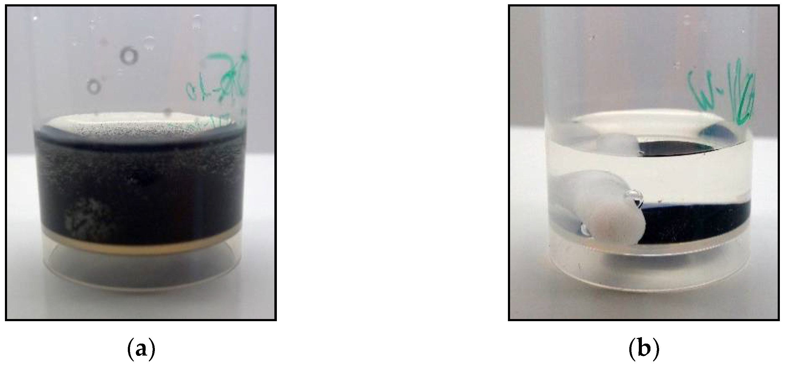
  • Stability of the binder polymer in aqueous electrolyte (no peeling of the coating from the current collector due to dissolution or strong swelling of the binder polymer).
  • Porosity of the coating for high specific surface area to provide a high (electrochemically active) surface area.
  • Wetting of the coating by the aqueous electrolyte to enable deposition and intercalation processes of the dissolved components of the electrolyte.
  • Advantageous transport characteristics of the porous electrode for the ions and electrons.
Herein, selected BPs (polyacrylonitrile (PAN), carboxymethyl cellulose (CMC), styrene butadiene rubber (SBR), cellulose acetate (CA), nitrile butadiene rubber (NBR)) with aqueous and non-aqueous solvents (DI-water, methyl ethyl ketone (MEK), and dimethyl sulfoxide (DMSO), for details see Section 4.1. Materials) are compared by applying a mechanical stress test (MST) on the positive electrode sheet and rate capability tests (RCT), together with electrochemical impedance spectroscopy (EIS) measurements, on experimental battery cells. The experimental results are compared with SEM+EDX images of cross-sections of pristine and cycled electrode sheets, giving further insights into the homogeneity, material distribution and morphology of the coatings. Furthermore, the mixing ratio of the electrode components is systematically investigated by using a ternary plot visualization to evaluate the influence of the different shares of the positive electrode ingredients on the mechanical stability of the coating and the cycling performance. Finally, recommendations for the selection of the binder polymer and the mixing ratios for the utilization in ARZIBs are made.
This study, besides well-known binder polymers such as CMC, SBR and LA133, also considers new BP/solvent combinations such as PAN+DMSO, NBR+MEK and CA+MEK for the utilization in ARZIBs.
As there are only few publications dealing with a comparison of different binder polymers for ARZIBs in literature (to our knowledge, only [4]), this publication is intended to provide a basis for comparing different BP/solvent combinations as well as different mixing ratios for the positive electrode fabrication. Hereby, the focus is set on NMP-free solvents, as NMP-free processing enables lower safety precautions (note: reproductive toxicity of NMP) and a clean-room-free processing, lowering the production costs and being a decisive advantage over the lithium-ion battery technology.

2. Results and Discussion

2.1. Binder Polymer Variation

For the binder polymer (BP) variation, different BPs based on aqueous solutions or dispersions, as well as non-aqueous solutions, were investigated. Since an aqueous electrolyte is used in the cell, the mechanical stability and structural integrity, especially of those electrodes produced with an aqueous binder preparation, were of interest.
In the following, the BPs based on aqueous solvent preparations are summarized as aqueous electrodes, whereas the BPs based on non-aqueous solvent preparations are summarized as non-aqueous electrodes.

2.1.1. Mechanical Stress Test (MST)

For the evaluation of the stability and structural integrity of the electrode coating with different BPs, the electrode coins were first mechanically tested by applying a mechanical stress test (MST).
Interestingly, after the MST, the aqueous electrode coatings are washed off and dissolved in DI-water (see Table 1a–d) leading to a turbidity of the solution (see Figure 1a). For the electrolyte solution, the MST shows no dissolution of the coating. Only the PVP binder flakes off the current collector in the electrolyte solution, but still does not dissolve. In contrast, the non-aqueous electrode coatings are stable in both DI-water and electrolyte solutions (see Table 1e–g and Figure 1b). The results of the MST follow the observations seen in Chang et al. (2020) for the non-aqueous binder (here: PVDF+NMP) and the aqueous CMC binder [4].
For the aqueous binders, the different behaviour in DI-water and electrolyte solution could be referred to the reduced solvation free energy of the water molecules in consequence of the ZnSO4 and MnSO4 addition in the electrolyte ([50] and Supplementary Figure S12), retarding and reducing the BP dissolution: Instead of a dissolution, the BP could only swell while still maintaining the structural integrity of the coating.
For the non-aqueous binders, as was expected, both the DI-water and the aqueous electrolyte solution are not affecting the structural integrity of the coating during the MST. Furthermore, in consequence of the non-aqueous processing of the coating, no swelling of the coating should occur here, in contrast to the previous aqueous binder coatings.
Based on the observations of the MST, a different behaviour during the cycling of the aqueous and non-aqueous electrodes in the aqueous ZnSO4/MnSO4 electrolyte is expected and shown in the following section.

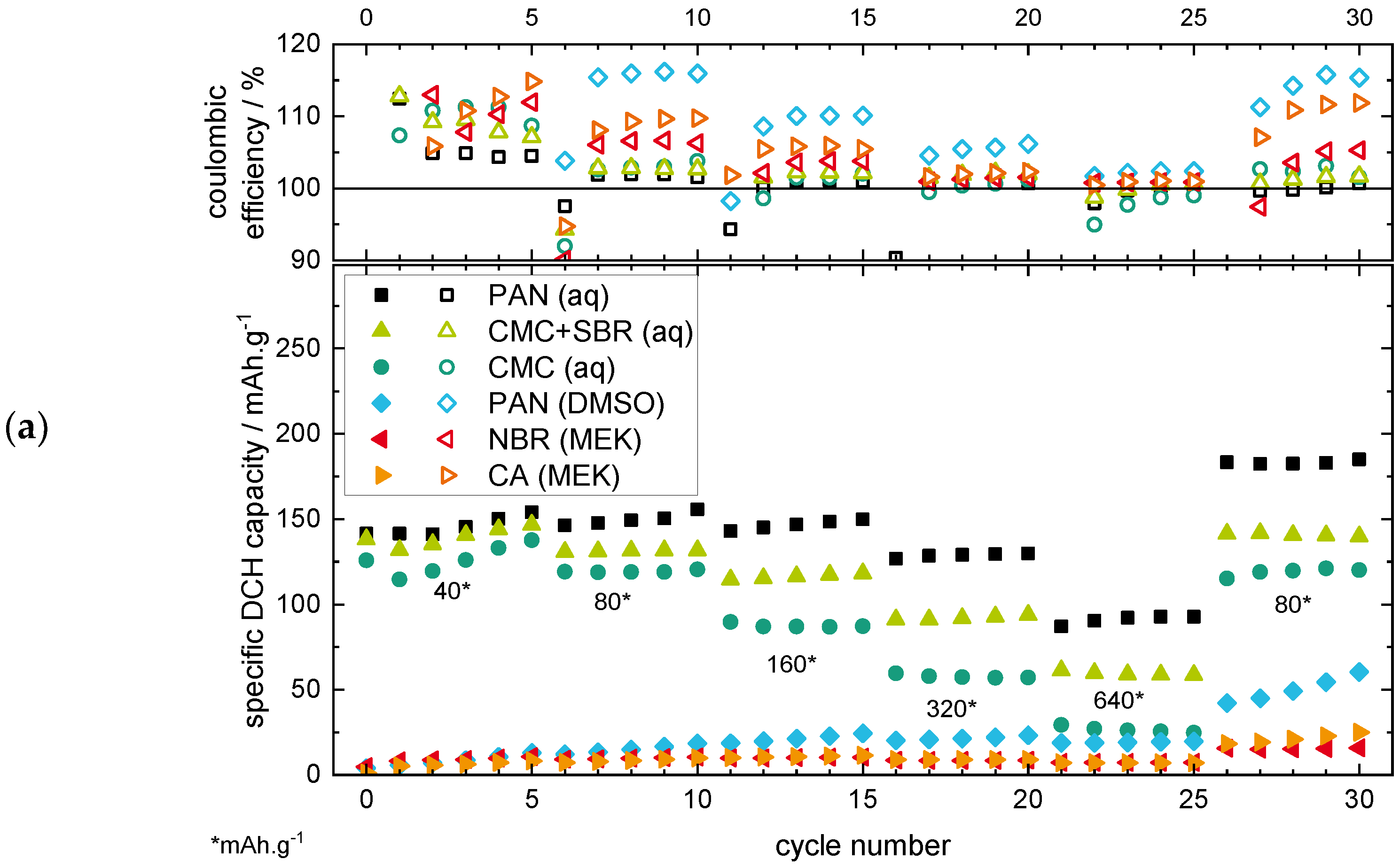
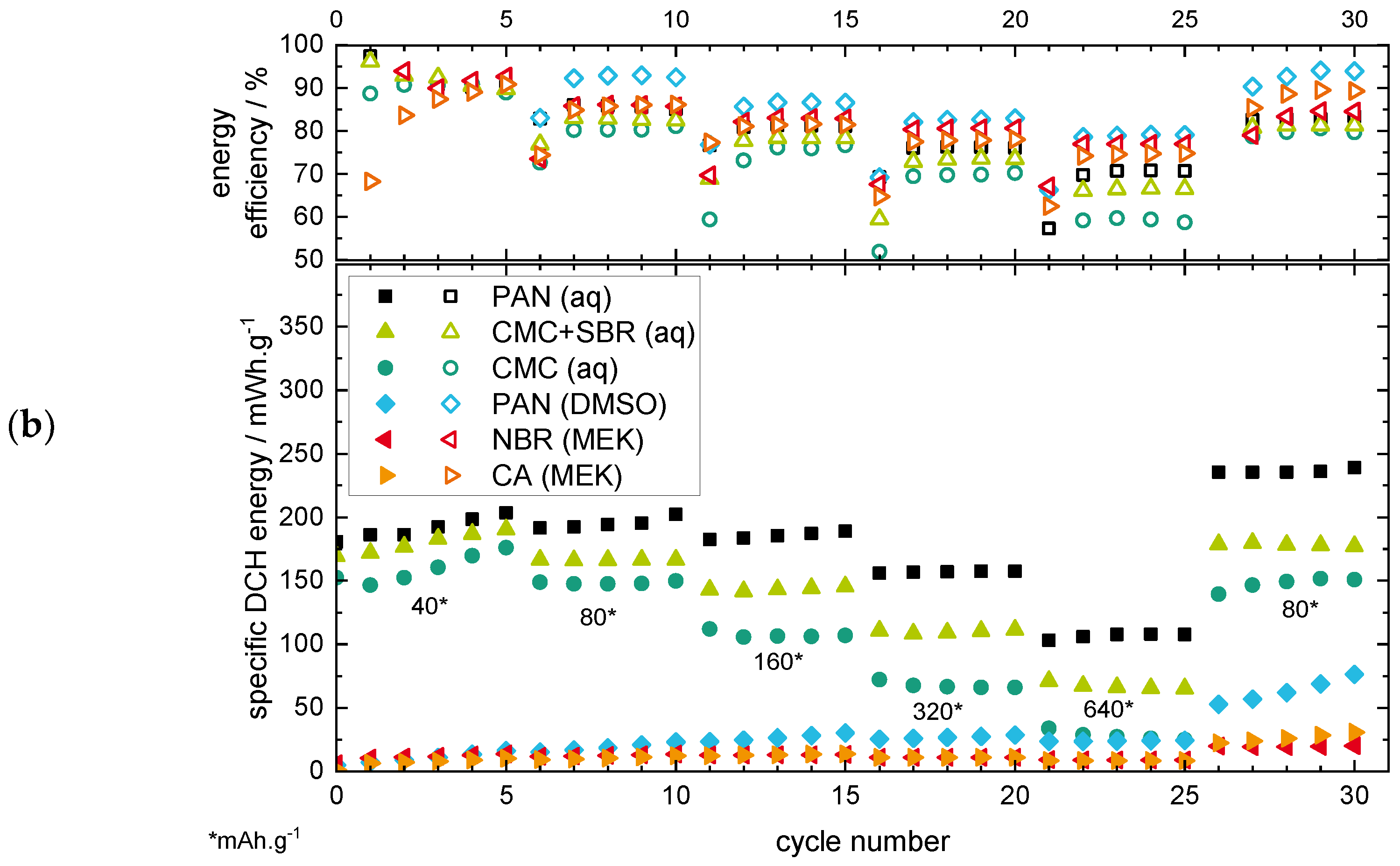
2.1.2. Rate Capability Test (RCT)

For the evaluation of the electrochemical performance of the electrode coatings with different BPs and solvents (see Table 2), a rate capability test (RCT) was performed under various current rates. The current rates are given in mA·g−1 based on the active material mass loading. The RCT results are shown by plotting both the specific discharge (DCH) capacity as well as the specific discharge energy, together with the efficiency values, over the cycle number, which allows a more in-depth analysis of the effects of the different binder types.
The results of the RCT with specific capacities (see Figure 2a) shows significantly higher capacity values for all the aqueous binders compared to the non-aqueous binders.
The aqueous PAN-based electrode shows the highest specific capacity for all current rates with ~150 mAh·g−1 at 40 mA·g−1 and ~90 mAh·g−1 at 640 mA·g−1. Both the CMC+SBR and the CMC binders show lower capacity values, with the lowest values for the pure CMC binder. The better performance of the CMC binder with SBR addition could be related to the better adhesion of the coating on the current collector, as well as a better flexibility of the coating through the addition of the SBR elastomer [51]. The PVP binder, which showed a flaking off the current collector in the MST, was not able to finish the RCT, which can be related to the low stability of the electrode coating (see RCT results in Supplementary Figure S6). Therefore, the PVP binder will not be discussed further in the following sections.
The non-aqueous binders show low-capacity values <20 mAh·g−1 in the first cycles, but interestingly it is with an increasing trend, even if the current rate increases. This is especially prevalent during the last cycles with 80 mA·g−1, as the increasing discharge capacity trend becomes clearly visible. This behaviour can be related to the surface deposition/dissolution of MnO2 as the predominant reaction mechanism for the non-aqueous electrode, whereby a growing MnO2 surface layer could be formed on the positive electrode [19,33,37,40,41]. The lower overall discharge capacity of the non-aqueous binders compared to the aqueous binders could be related to the observations of the MST results of the previous section, where a swelling and wetting of the electrodes in the electrolyte was suggested for the aqueous but not (or to a lesser extent) for the non-aqueous electrode coatings. In consequence, the MnO2 active material loading of the electrode coating could only become available for the aqueous binders by dissolution/deposition processes during charging/discharging, leading to additional capacity. This suggestion is confirmed by the latest literature for ARZIBs [19,33,37,40,41]. For the non-aqueous binders, the active material loading could mainly be isolated by the binder.
The coulombic efficiencies (CE, see Figure 2a) for all the binder types are located above or at ~100%, which again can be related to the MnO2 deposition/dissolution process. The dissolution of the MnO2 active material loading as well as the additionally deposited MnO2 could lead to an additional discharge capacity, which results in CE values >100%. The CE values for the non-aqueous binders are generally located above the values for the aqueous binders, indicating a more dominant MnO2 deposition/dissolution mechanism. This could be related to the inactivity of the isolated MnO2 loading within the positive electrode coating, as no swelling of the binder is suggested (see MST section), which could enable a material deposition/dissolution only on the surface of the electrode with better efficiency values.
The RCT results showing the specific energy (see Figure 2b) additionally reveal the effects of overpotentials during charge/discharge by also considering the potential value (besides the capacity value, see the equation in Supplementary Figure S5) of the particular cycle. As the energy output of a battery system is of even higher importance for the application than only the capacity output, this way of plotting can be regarded as being a more application-oriented plot. For the specific energy plots, the comparison of the aqueous/non-aqueous binder types show the same characteristics as the specific capacity plots. Nevertheless, distinctions in terms of the energy efficiency (EE) values are noticeable: the EE values decrease for increasing current rates. This indicates an increasing inner resistance and overpotential of the cell [52]. For the non-aqueous binders, the energy efficiency values are generally located above the values of the aqueous binders, as seen before in the capacity plot, again indicating a more dominant MnO2 deposition/dissolution mechanism.
In Figure 3, the potential curves for the 10th and 30th cycle, respectively, each with the current rate of 80 mA·g−1, are shown for the non-aqueous binders. Generally, the shape of the discharge curves of all binder/solvent combinations show two potential plateaus divided by a potential bend (see exemplarily Figure 3, marker 1). The charge curve again shows two potential plateaus (see Supplementary Figure S11 for more details). The potential curves of the non-aqueous binders (see Figure 3b) each have a significant increase in the specific capacities compared to the aqueous binders (see Figure 3a). Nevertheless, the potential curves characteristics stay the same, as the characteristic potential bend for ARZIBs (with MnO2 active material) indicates (see Figure 3, marker 1). The potential curves also show that the capacity increase from the 10th to the 30th cycle is the highest for both of the PAN-based electrodes (aqueous and non-aqueous), which could explain the good overall performance of the aqueous PAN-based electrode in the RCT (see Figure 2a).
By performing SEM+EDX characterizations (see Figure 4), the cross-sections of electrode coatings of PAN (aq) and PAN (DMSO), prepared by ion-polishing, were compared in a pristine state and in discharged state after the RCT procedure (post-mortem state). This way, the influence of an aqueous and non-aqueous BP could be investigated in more detail.
For both the pristine PAN (aq) and (DMSO) electrodes, the MnO2 particles (coloured green) and the CB content (coloured orange) show comparable morphology characteristics such as the homogeneity, the porosity, and the material distribution (see Supplementary Figure S7 for EDX images of the single elements, respectively).
Interestingly, after the RCT procedure (post-mortem) in the discharged state, both electrodes show a surface layer deposition, which is thicker for the PAN (aq) electrode and could be attributed to a MnO2 deposition (see Figure 4d,h, marker 1), as described in the previous literature [19,33,37,40,41]. Furthermore, both electrodes in a post-mortem state (discharged state) show a new flake structure inside the electrode coating (see Figure 4c,d,g,h, circle), which is not visible in the pristine state (see Figure 4a,b,e,f). This could be attributed to ZHS precipitations filling the pores of the electrode coating, as described in the previous literature [14,19,33,37,40,41,42,43,44]. However, this precipitation seems to be less distinctive for the PAN (DMSO) coating. This could be explained by the previously mentioned assumption of less wetting of the electrode coating by the electrolyte and thus a smaller active inner surface, as the CB-containing, electrically conductive coating could mainly act as an electrochemically active surface. Hence, this could result in a lower capacity by the dissolution of the (mostly unavailable) MnO2 active material loading during discharge, compared to the PAN (aq) coating. The flake structure (see Figure 4c, marker 2) on the surface of the electrode can be referred to the separator with electrolyte salt residues, which was stuck on the electrode coating surface (possibly due to the aforementioned MnO2 deposition).
Altogether, the comparison of the SEM+EDX images in a pristine and post-mortem (discharged) state could confirm the existence of a MnO2 deposition during the charge steps, which takes place both in the pores of the electrode coating (if available, depending on the binder/solvent combination, as previously discussed) as well as on the surface of the electrode. In the following discharge steps, the previous MnO2 deposition dissolves again, releasing capacity, which should be higher for those electrodes whose MnO2 active material loading is available for the deposition/dissolution mechanism (here: PAN (aq) electrode coating, see RCT results). Due to efficiency reasons of the dissolution, MnO2 deposition residues seem to stay, leading to an accumulating MnO2 (surface) deposition layer (here: thicker surface layer for PAN (aq) than for PAN (DMSO) coating).
For a better understanding of the MnO2 deposition/dissolution mechanism, further SEM+EDX characterizations of cross-sections of the positive electrode coatings in different states of charge should be carried out to further prove the latter assumptions of this study.
To underline the findings of the RCT tests for the aqueous and non-aqueous electrodes, the electrical impedance spectroscopy (EIS) measurements of the positive electrode (vs. Zn/Zn2+ reference) were analysed for the PAN (aq) and PAN (DMSO) binder in a charged (CH) and discharged (DCH) state to compare the effects of the different solvent categories as an example (for all the EIS results, see Supplementary Figure S8). The choice of these two binder combinations allowed for a direct comparison of the influence of the non-aqueous solvent (DI-water vs. DMSO) without the influence of the binder polymer (here, the LA133 binder is considered as a PAN-based binder since the specification of PAN in the safety data sheet is >95 wt% of solid content). In Figure 5, the EIS results of the positive electrode are shown.
For the different PAN binder solvents and state of charges, the following qualitative interpretations of the Nyquist plot can be made:
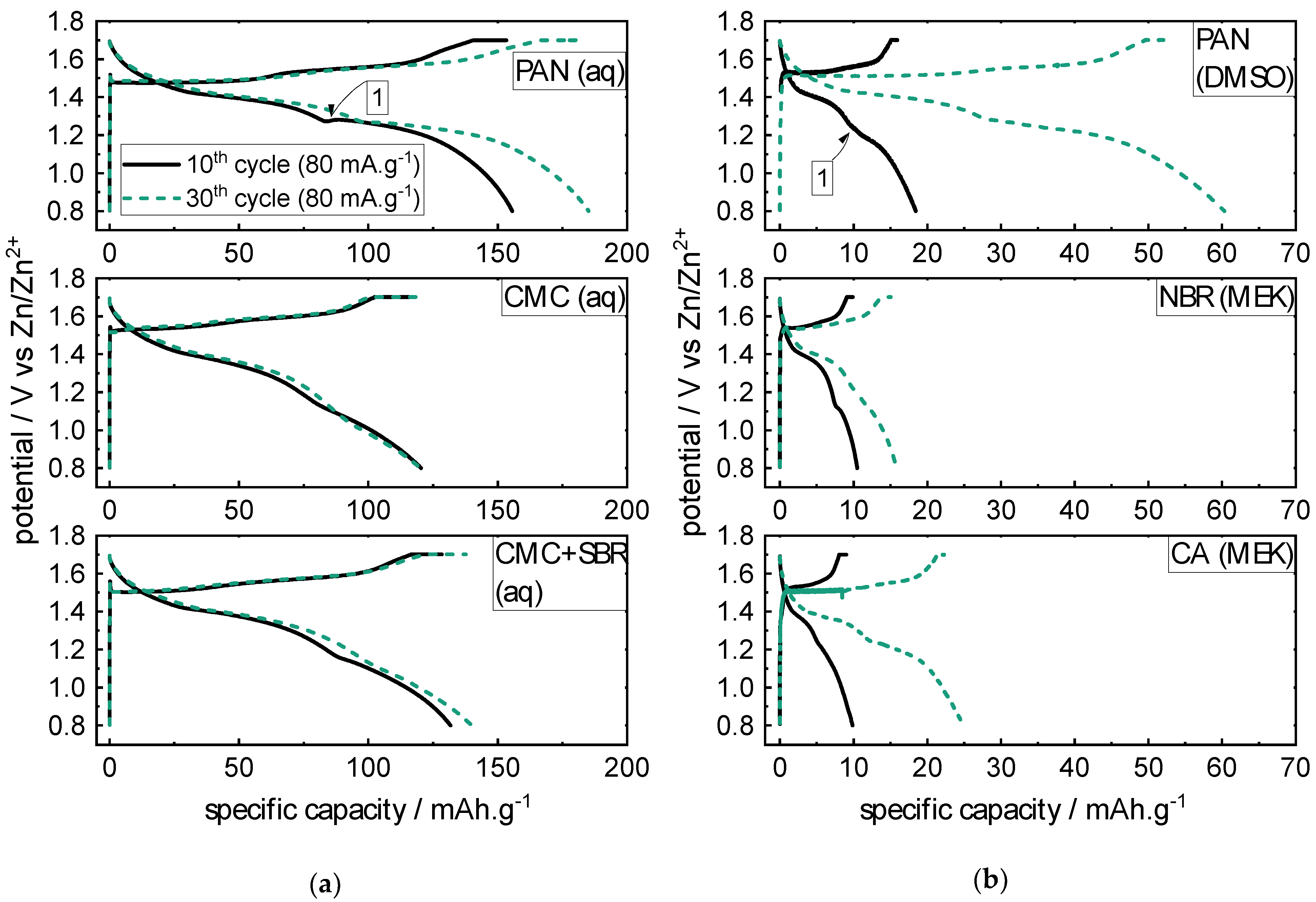
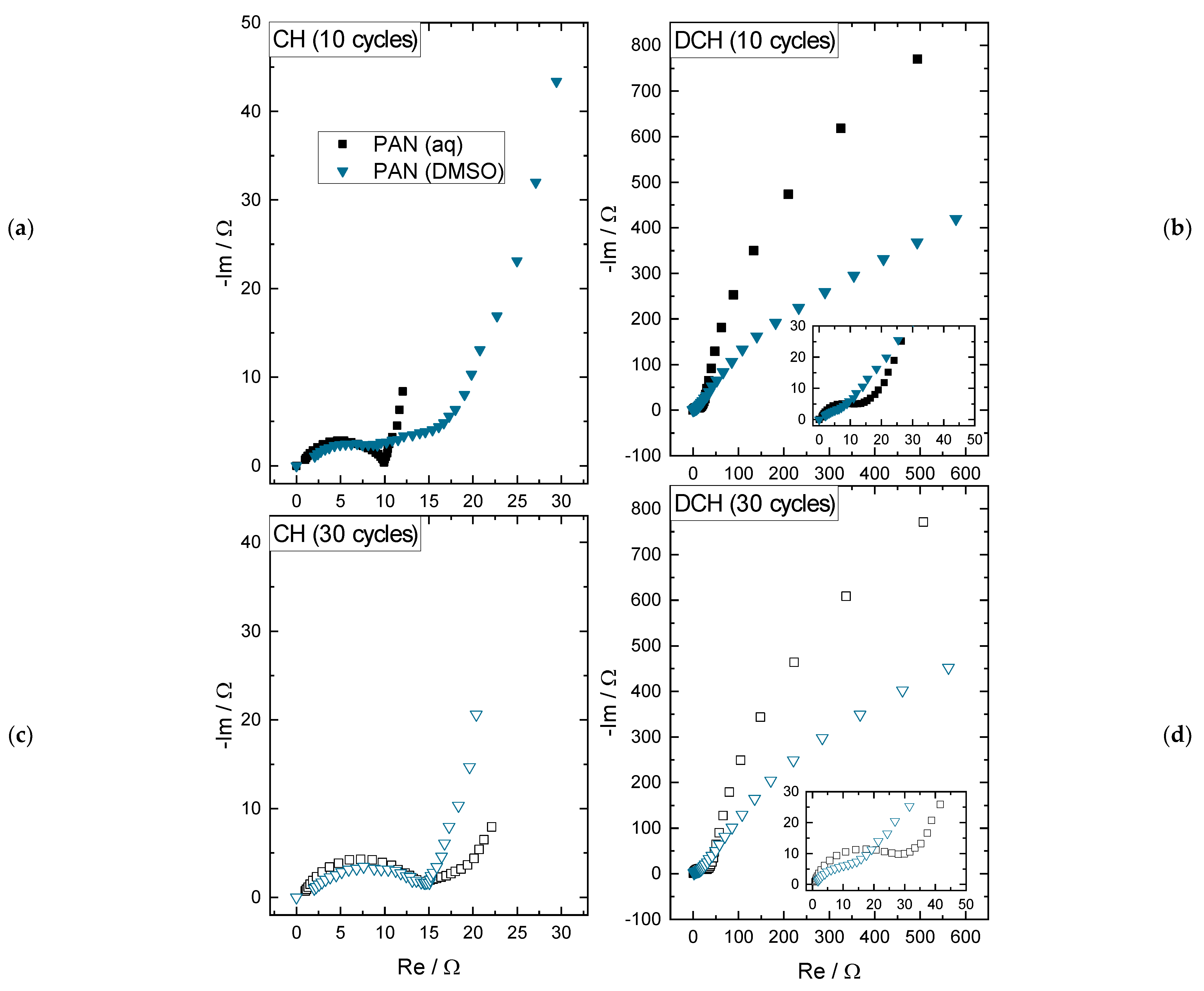
  • In charged state after 10 cycles (see Figure 5a), there is a lower impedance for the PAN (aq) than for the PAN (DMSO) electrode: The double layer (DL) capacity and the charge transfer (CT) resistance of the PAN (aq) binder are both clearly visible as a semi-circle, whereas the DL capacity and CT resistance of the electrode PAN (DMSO) binder is stretched, which indicates a higher CT resistance and could refer to the inactive and isolated MnO2 active material particles in the electrode coating.
  • In charged state after 30 cycles (see Figure 5c), the impedance spectra show quite comparable semi-circles, again representing the DL capacity and the CT resistance. This could be explained by the growing deposition layer of MnO2 on the positive electrode surface of the PAN (DMSO) coating. This assumption is supported by the capacity increase of the PAN (DMSO) electrode in Figure 2a.
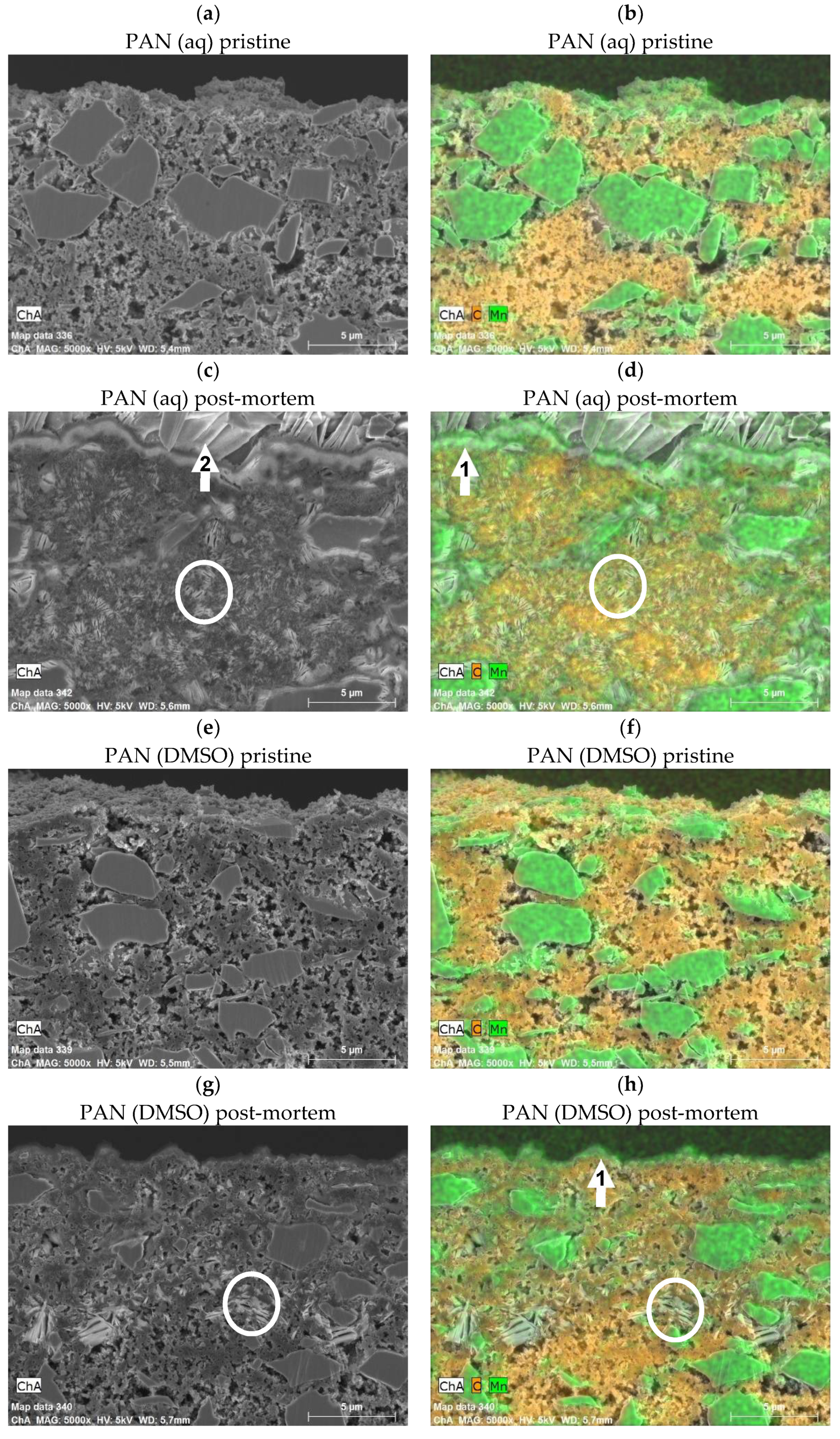
  • In discharged state after 10 and 30 cycles (see Figure 5b,d), the overall impedances increase by about two orders of magnitude for both PAN (aq) and PAN (DMSO). This can be explained by the precipitation of ZHS as a consequence of the MnO2 dissolution, as discussed in [19]. The precipitation results in a new DL capacity with a higher CT resistance, which is shown by the large low frequency half circle. Still, the impedance spectra for the lower impedance values are visible (see insets in Figure 5b,d), which were previously discussed for the charged state representing the MnO2 active material layer. Relating to the PAN (DMSO) binder, the capacitive part of the impedance spectra is still below the PAN (aq) spectra, which can be explained by the thinner MnO2 deposition layer and less ZHS precipitation (less wetting of the coating), resulting in lower specific capacity values (see Figure 2a).
Altogether, the comparison of the aqueous/non-aqueous electrodes generally shows higher discharge capacities/energies for the aqueous binders, which is related to the availability of the MnO2 active material loading. The MnO2 active material loading is not available in the non-aqueous electrodes, as the electrolyte should not lead to an electrode coating swelling as suggested, in contrast, for the aqueous electrodes. Nevertheless, the non-aqueous electrodes show increasing discharge capacities/energies with proceeding cycles, underlining the major role of MnO2 deposition/dissolution processes (also on the surface of the electrode) for the ZIB with ZnSO4/MnSO4-based electrolytes being introduced in the recent literature.
As the aqueous PAN-based LA133 binder shows the best cycling results, this binder was chosen for the mixing ratio variation shown in the following section.

2.2. Mixing Ratio Variation

Beside the variation of the BP itself (with fixed mixing ratios of AM/CB/BP 70/20/10 wt%), the influence of different mixing ratios was systematically investigated. The goal of the variation was to improve the energy density of the positive electrode. Therefore, this variation aimed at finding an advantageous mixing ratio with maximized active material share while still maintaining the electrochemical performance (i.e., the electrical conductivity driven by the CB content). The investigated mixing rations are graphically summarized using a ternary plot visualization in Figure 6.
The following criteria were considered for the positive electrode coatings:
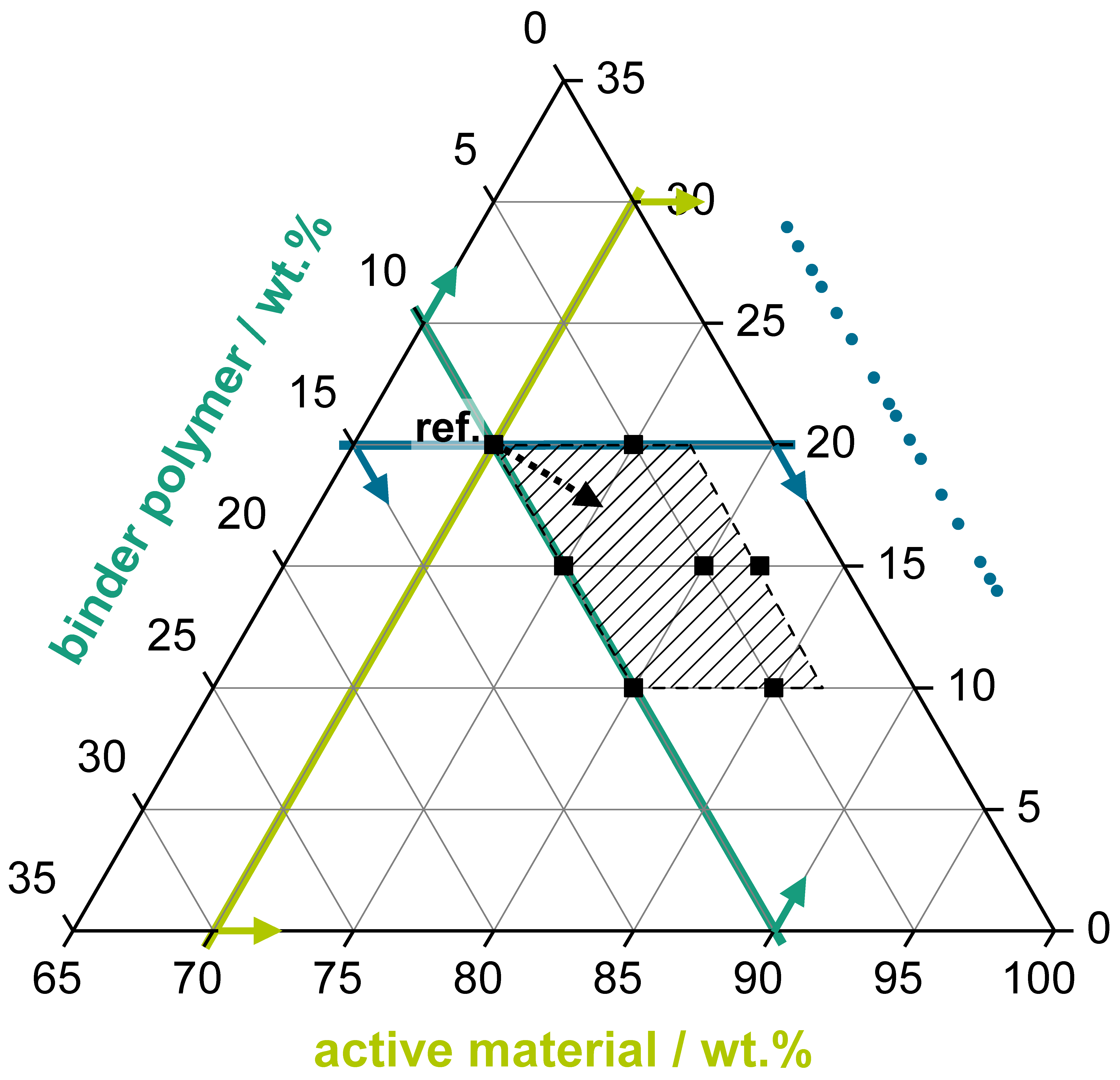
  • An active material proportion as high as possible to reduce the share of the passive materials (carbon black, binder polymer) in the electrode coating.
  • A binder polymer proportion as low as possible to reduce the share of a passive and electrically non-conducting coating component.
  • A carbon black proportion as low as possible, while still enabling a sufficient electrical conductivity of the coating.
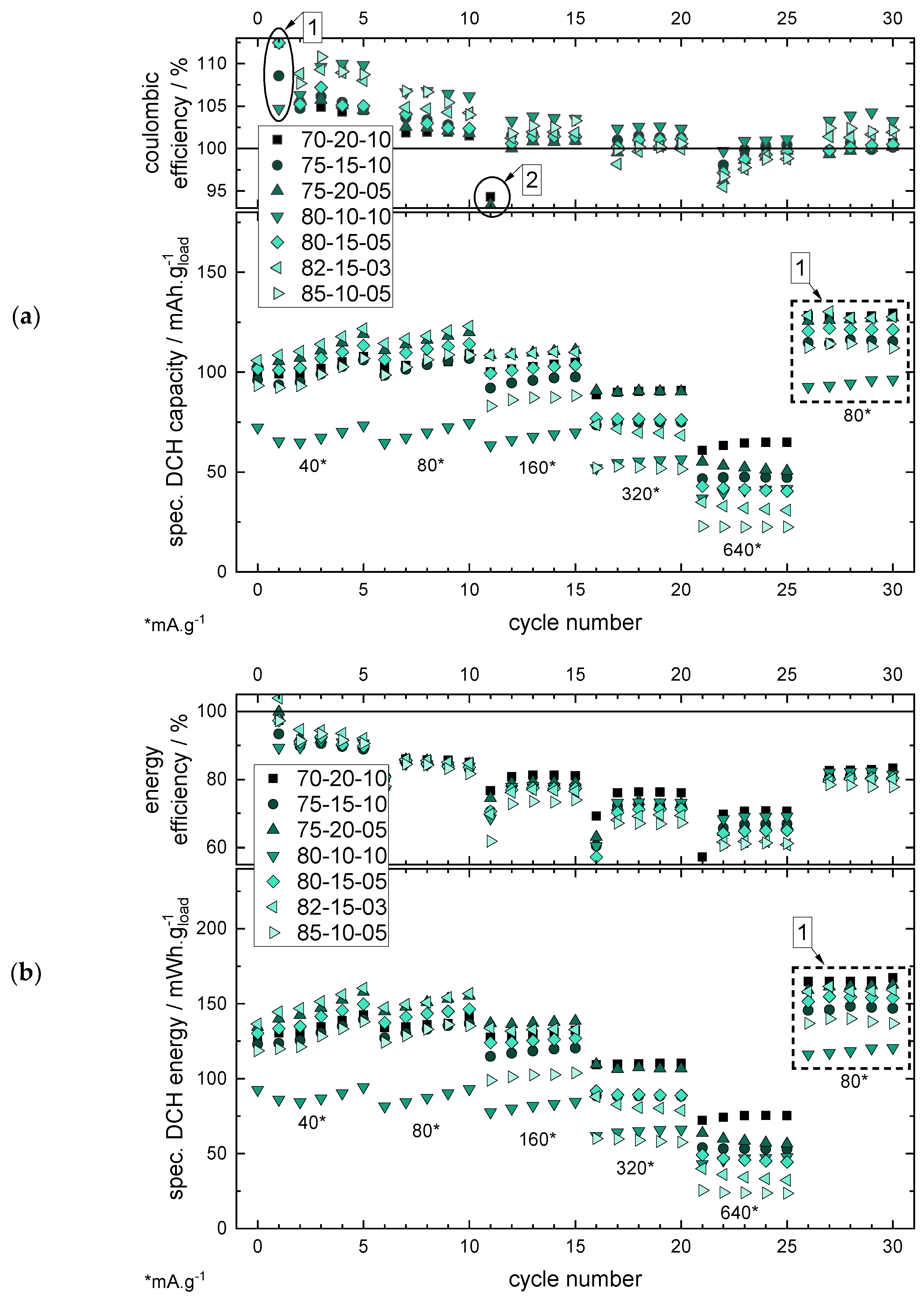
  • Good cycling performance in the RCT considering different application fields such as high-power (current rates >1 C, here: >160 mA·g−1 based on an experimentally determined capacity of ~160 mAh·g−1 of MnO2) and high-energy (<1C, here: <160 mA·g1) applications.
In Figure 7, the results of the RCT are shown by plotting the specific capacities and energies for different current rates over the cycle number. Here, the specific values were calculated by dividing the absolute capacity values by the total mass loading of the electrode (AM, CB, and BP, instead of only considering the AM mass loading as for the binder polymer variation in Section 2.1). This calculation method was chosen to be able to identify the influences of the different mixing ratios of the electrode coatings on the resulting capacity and energy values, respectively.
The results of the RCT with the specific discharge capacities (see Figure 7a) show that a low polymer binder percentage of 3 wt% is possible in the electrode coating, still enabling a cycling with a discharge capacity of ~140 mAh·g−1 @ 40 mA·g−1. Nevertheless, the CB share, especially, and its ratio to the BP share has a high influence on the current rate stability:
  • Lowering the CB share allows reducing the BP share.
  • Reducing the CB share without reducing the BP share results in poor cycling behaviour due to insufficient conductivity within the electrode.
Therefore, a higher ratio of CB to BP improves the performance, as for the 75/20/05 mixture with a CB/BP ratio of 4 (20 wt% divided by 5 wt%) the performance for all current rates is significantly better compared to the 80/10/10 mixture with a CB/BP ratio of 1 (10 wt% divided by 10 wt%). For the other mixtures with ratio values between 1.5 to 3, the performances are located between the above-mentioned mixtures. The interpretation of the results by analysing the CB/BP ratio can be explained as the lower the CB/BP ratio, the lower the electrical conductivity of the electrode coating—resulting in a higher share of electrically isolating BP.
This observation leads to the differentiation of the interpretation of different CB shares depending on the application, i.e., high-power (HP) and high-energy (HE) applications.
  • For HP applications, a CB share of >15 wt% is necessary to still enable a good RCT capacity also at higher current rates >320 mA·g−1. The CB/BP ratio should be >2 (see 70/20/10 or 75/20/05).
  • For HE applications, an AM loading as high as possible is important for lower the specific costs of the battery, and therefore lower CB loadings are preferable. Considering this, a CB loading of 10 wt% and a CB/BP-ratio of ~2 (s. 85/10/05) still enables a good cycle performance at lower current rates <160 mA·g−1.
The RCT showing the specific discharge energies (see Figure 7b) also considers the potential, in addition to the capacity value, which provides a better insight into the inner resistance of the battery cell during cycling (see the previous section and Supplementary Figure S11). Although basically showing the same characteristics of the results of the different mixing ratios as the capacity representation (regarding the order of the different electrode material compositions, see marker 1), slight differences of the capacity vs. energy level order of the different mixture ratios can be observed, especially for the last RCT step with 80 mA·g−1, herein for the PAN (aq) binder as an example. The differences of the order of capacity/energy plots can refer to the different potential plateau levels during cycling, which is only considered by the energy representation (see the equation in Supplementary Figure S5).
Basically, this type of energy representation is introduced as a useful and more application-oriented alternative to the established capacity representation. This applies, in particular, to the aqueous battery chemistries such as the ARZIB technology with significant distinctions in the potential plateaus as a consequence of various cell constructions, as the literature shows.
Finally, it must be noted that the results were generated with the aqueous PAN-based LA133 binder. For other binder polymers, the results could differ. Still, the characteristics of the variation of the mixing ratio of the electrode components should stay comparable.

3. Conclusions

3.1. Binder Variation

Mechanical stress tests of the positive electrode coatings revealed the maintenance of the structural integrity of the coatings based on aqueous binders in the electrolyte solution but not in DI-water, in comparison to the non-aqueous binders showing a stability in both DI-water and electrolyte. This could refer to the lower solvation free energy of the water molecules in the electrolyte in consequence of the ZnSO4 and MnSO4 addition, stabilizing the aqueous binders.
Rate capability tests (RCT) showed a lower capacity/energy of the positive electrodes for the binder polymers with non-aqueous solvents compared to those with aqueous solvents, with the best results achieved for the aqueous binder PAN. This could be explained by the availability of the MnO2 active material loading of the coating: The aqueous binders allow a swelling of the coating by the electrolyte in contrast to the non-aqueous binders. The coating swelling makes the active material loading available for MnO2 deposition/dissolution mechanisms in relation to the suggested reaction mechanism of the ARZIB, resulting in higher capacity/energy values. Still, the non-aqueous binders show an increasing capacity/energy with the proceeding cycle number. This could be explained by a MnO2 deposition/dissolution mechanism on the electrode surface being confirmed by SEM+EDX characterizations of electrode cross sections. EIS measurements show that the characteristics of the spectra of the non-aqueous binder (here: PAN (DMSO)) in the charged state also changes by increasing the cycle number, which might indicate a growing MnO2 deposition layer for proceeding cycling.

3.2. Mixing Ratio Variation

Considering the results, the optimized mixing ratios must be chosen following the favoured application of the battery. Here, the absolute carbon black (CB) share of the coating and the ratio of the CB and the binder polymer (CB/BP-ratio) shares were investigated as important parameters for the electrode coatings of ARZIBs. For a CB share ≤15 wt% and CB/BP-ratios ≤2, the cycling performance decreases, whereas for a CB share >15 wt% and CB/BP-ratios >2 and up to 5, the cycling performance increases, respectively, also for high current rates. Therefore, higher CB shares qualify the positive electrode for usage in high-power applications, while reduced CB shares (but high active material shares) are suitable for high-energy applications. Furthermore, in terms of an industrial production approach, the proportion of the passive materials (CB+BP) was successfully reduced to 15 wt% in total, and the BP proportion to 3 wt%, still enabling the cycling of these battery cells.
This study sheds light on the influence of the binder polymer/solvent combination on the cell performance of ARZIBs through comparing (non-)aqueous solvents, as well as on the influence of the mixing ratio by minimizing the passive material share of the positive electrode. The results of this study can be used for application-oriented cell fabrication of ARZIBs.

4. Materials and Methods

4.1. Materials

For the positive electrode preparation, manganese dioxide (AM, Manganese(IV) oxide, 99.9% (metals basis), 325 mesh powder, Alfa Aesar, Heysham, United Kingdom), Carbon black (CB, Carbon black, acetylene, 100% compressed, 99.9+%, Alfa Aesar, Heysham, United Kingdom), binder polymer (BP) and solvent were mixed in different combinations in a speed mixer (DAC 150.1 FVZ-K, Hauschild and Co.KG, Hamm, Germany) at 3000 rpm for 2 min. Subsequently, the positive electrode aqueous slurry was homogenized in a three-roll mill (EXAKT 80E, EXAKT Advanced Technologies GmbH, Norderstedt, Germany) with a final roll gap of 10 µm to control and unify the particle sizes. Due to the evaporation and security characteristics of the solvents, the non-aqueous slurries were homogenized for 30 min at least at 2000 rpm in a laboratory dissolver (DISPERMAT CN10, VMA-GETZMANN GmbH, Reichshof, Germany) instead of being processed in the three-roll mill. The slurry was coated with a doctor blade and 200 µm wet layer thickness on a stainless-steel foil (1.4301/AISI 304, thickness 25 µm, TBJ Industrieteile GmbH, Leipzig, Germany). The AM mass loading was ~2.5–4.6 mg/cm−2 and the electrode coating thickness ~40 µm (see Supplementary Figure S10). Afterwards, the coating was dried for 24 h at 40 °C. Then, 16 mm coins were used as positive electrodes. As the negative electrode, a 25 µm thick zinc foil with the diameter of 16 mm was used (zinc foil 99.95%, Goodfellow GmbH, Hamburg, Germany). The separator (18 mm diameter) was made of glass fibre filter (Whatman® GF/A, Cytiva Europe GmbH, Freiburg, Germany). For the electrolyte, zinc sulfate heptahydrate (AnalaR NORMAPUR® Reag. Ph.Eur., ACS for analysis, VWR International GmbH, Darmstadt, Germany) and manganese sulfate tetrahydrate (99%, metal basis, Alfa Aesar, Heysham, United Kingdom) were used. A zinc wire (99.9% pure zinc wire, Goodfellow GmbH, Hamburg, Germany) was used as the reference electrode.
For the BP study, the following binders have been investigated:
  • LA133 (polyacrylonitrile (PAN)-based aqueous binder dispersion, GELON LIB Group, Linyi, China)
  • SBR (styrene-butadiene rubber, SSBR 100, aqueous suspension, Targray, Kirkland, QC, Canada)
  • CMC (carboxymethyl cellulose, average MW ~250,000, degree of substitution 0.9, sodium salt, powder, Sigma-Aldrich, Merck KgaA, Darmstadt, Germany)
  • PVP (polyvinylpyrrolidone, MW 1,300,000, powder, Alfa Aesar, Heysham, United Kingdom)
  • CA (cellulose acetate, MW ~100,000, powder, Acros Organics, Thermo Fisher Scientific, New Brunswick, NJ, USA)
  • NBR (nitrile butadiene rubber, acrylonitrile 37–39 wt%, chunk, Sigma-Aldrich, Merck KgaA, Darmstadt, Germany)
  • PAN (polyacrylonitrile, copolymer 99.5% AN/0.5% MA, MW 230,000, powder, Goodfellow GmbH, Hamburg, Germany)
For the slurry preparation, aqueous and non-aqueous binder solutions/suspensions were prepared: For the aqueous slurry preparation, DI-water and for the non-aqueous slurry preparation, methyl ethyl ketone (MEK, for NBR and CA) or dimethyl sulfoxide (DMSO, for PAN) were used. The binder preparations are listed in Table 2.
In order to evaluate the material shares of active material, conductive agent and binder polymer, different mixing ratios were tested. For this purpose, the PAN-based aqueous LA133 was used exemplarily as the binder. The share combinations listed in Table 3 have been tested.

4.2. Cell Assembly

Cells were assembled using EL-Cell® ECC-Aqu experimental cells. A glass fibre separator with a diameter 18 mm was used. Two hundred µL of an aqueous electrolyte containing 2 M ZnSO4 and 0.1 M MnSO4 was used (pH~4). The zinc wire was used as the reference electrode in the EL-Cell® ECC-Aqu. As the current collector on the positive electrode, an 18 mm stainless steel coin was used. As the current collector on the negative electrode, an 18 mm copper coin was used. The cell setup is shown in Supplementary Figure S2.

4.3. Characterization Methods

The cell cycling was performed by making a rate capability test (RCT) with 5 cycles, each at 40, 80, 160, 320, 640, and 80 mA·g1 (related to active material loading of the manganese dioxide electrode) from 0.8 to 1.7 V with a VMP3 potentiostat from Biologic Science Instruments, Seyssinet-Pariset, France. The charging process included a constant current (CC) step followed by a constant voltage (CV) step until 10% of the current in the CC-step was reached. The discharge process was performed at CC. EIS measurements were performed between 10 kHz and 20 mHz at 1.7, 1.25 and 0.8 V cell voltage after the five 80 mA·g1 charge/discharge cycles, respectively. The test plan procedure is shown in detail in Supplementary Figure S3.
For the mechanical stress test (MST), the electrode coins were put into a transparent PP beaker (20 mL, ø31 × 48 mm) filled with the same amount (~10 mL) of either DI-water or electrolyte solution together with a magnetic stirring bar on top of the electrode sheet. The stirring bar (PTFE, cylindrical, length 20 mm) was operated for 60 s at 200 rpm, respectively. The experimental setup is visualized in Supplementary Figure S4.
For analysing the distribution of the different components in the positive electrode, SEM-EDX images were realized with selected positive electrodes. The positive electrodes were dipped into deionized water and dried overnight before being ion polished. The cutting edges were prepared by ion milling (IM4000 Ion Milling System, Hitachi High-Tech Europe GmbH, Mannheim, Germany) and characterized by SEM (Zeiss Auriga 60, Carl Zeiss Microscopy Deutschland GmbH, Oberkochen, Germany) and EDX (Bruker Quantax XFlash 6160, Bruker Corporation, Billerica, USA).

Supplementary Materials

The following are available online at https://0-www-mdpi-com.brum.beds.ac.uk/article/10.3390/batteries7020040/s1, Figure S1: Overview of the experimental cell setup inside the EL-Cell® ECC aqu, Figure S2: Graphical overview of the test plan procedure for the rate capability test of the herein tested cells, Figure S3: Experimental setup of the mechanical stress test with a magnetic stirring bar in a PP beaker (20 mL, ø31 × 48 mm) filled with ~ 10 mL of liquid, Figure S4: RCT results including the PVP (aq) binder polymer, which is not finishing the RCT due to stability issues of the electrode coating (s. MST), Figure S5: Potential curves including the PVP binder, which was not able to finish the RCT, Figure S6: Comparison of the PAN (aq) and the PAN (DMSO) coating in pristine state. MnO2 particles are coloured green, carbon black is coloured orange, Figure S7: Comparison of the PAN (aq) and the PAN (DMSO) coating in post mortem state. MnO2 particles are coloured green, carbon black is coloured orange, Figure S8: Overview of the EIS spectra for all investigated binder polymers in charged (CH) and discharged (DCH) state after 10 and 30 cycles, respectively, Figure S9: Diagrams of the RCT showing the specific capacity and energy, respectively, together with the efficiency values, Figure S10: SEM+EDX images of the coating with aqueous LA133 (PAN-based) binder with the mixing ration 70/20/10 (AM/CB/BP, wt%) in pristine state. The electrode thickness is ~40 µm, Figure S11: SEM+EDX images of the coating with aqueous LA133 (PAN-based) binder with the mixing ration of 80/15/05 (AM/CB/BP, wt%) in pristine state. The electrode thickness is ~40 µm. (green coloured = MnO2 particles, orange coloured = carbon black (CB)), Figure S12: Comparison of the 70/20/10 and 80/15/05 binders in pristine state. For the 80/15/05 coating, smaller distances of the MnO2 active material particles (coloured green) and a more compact visual impression of the coating could be assumed, which could be referred to the lower CB content and the lower overall passive material (CB+BP) share (20 wt% instead of 30 wt% for the 70/20/10 coating), Figure S13: Overview over the charge/discharge curves of the 10th cycle (80 mA·g−1) of the RCT shown in Figure S4 for the binder variation (a) and mixing variation (b) with insets showing the IR drops directly after the switchover from charge to discharge (marker 1) and the first potential plateau during discharge (marker 2), Table S1: Brief literature research on binder materials, solvents, mixing ratios and current collectors. This literature search was carried out as an example and does not claim to be complete, Table S2: Detailed Overview of the test plan procedure for the RCT.

Author Contributions

Conceptualization, O.F.; methodology, O.F., S.I. and C.B.; validation, O.F., S.I. and C.B.; formal analysis, O.F.; investigation, S.I., C.B. and O.F.; data curation, O.F. and S.I.; writing—original draft preparation, O.F.; writing—review and editing, H.G., S.I., C.B., K.P.B. and D.B.; visualization, O.F.; supervision, D.B., K.P.B. and D.S.; project administration, D.B. All authors have read and agreed to the published version of the manuscript.

Funding

This research received no external funding.

Data Availability Statement

The data presented in this study are available on request from the corresponding author.

Acknowledgments

Oliver Fitz acknowledges the German Federal Environmental Foundation (Deutsche Bundesstiftung Umwelt, DBU) and Christian Bischoff acknowledges the Heinrich Böll Foundation for the support. We thank Volker Kübler for carrying out the SEM+EDX characterizations.

Conflicts of Interest

The authors declare no conflict of interest.

References

  1. Biswal, A.; Tripathy, B.C.; Subbaiah, T.; Meyrick, D.; Minakshi, M. Electrodeposition of manganese dioxide: Effect of quaternary amines. J. Solid State Electrochem. 2013, 17, 1349–1356. [Google Scholar] [CrossRef] [Green Version]
  2. Biswal, A.; Tripathy, B.C.; Subbaiah, T.; Meyrick, D.; Minakshi, M. Dual effect of anionic surfactants in the electrodeposited MnO2 trafficking redox ions for energy storage. J. Electrochem. Soc. 2015, 162, A30–A38. [Google Scholar] [CrossRef] [Green Version]
  3. Song, M.; Tan, H.; Chao, D.; Fan, H.J. Recent advances in Zn-ion batteries. Adv. Funct. Mater. 2018, 28, 1802564. [Google Scholar] [CrossRef]
  4. Chang, H.J.; Rodríguez-Pérez, I.A.; Fayette, M.; Canfield, N.L.; Pan, H.; Choi, D.; Li, X.; Reed, D. Effects of water-based binders on electrochemical performance of manganese dioxide cathode in mild aqueous zinc batteries. Carbon Energy 2020. [Google Scholar] [CrossRef]
  5. Olbasa, B.W.; Fenta, F.W.; Chiu, S.-F.; Tsai, M.-C.; Huang, C.-J.; Jote, B.A.; Beyene, T.T.; Liao, Y.-F.; Wang, C.-H.; Su, W.-N.; et al. High-rate and long-cycle stability with a dendrite-free zinc anode in an aqueous Zn-Ion battery using concentrated electrolytes. ACS Appl. Energy Mater. 2020, 3, 4499–4508. [Google Scholar] [CrossRef]
  6. Pan, H.; Ellis, J.; Li, X.; Nie, Z.; Chang, H.J.; Reed, D. Electrolyte effect on the electrochemical performance of mild aqueous zinc-electrolytic manganese dioxide batteries. ACS Appl. Mater. Interfaces 2019. [Google Scholar] [CrossRef]
  7. Palaniyandy, N.; Kebede, M.A.; Raju, K.; Ozoemena, K.I.; Le Roux, L.; Mathe, M.K.; Jayaprakasam, R. α-MnO2 nanorod/onion-like carbon composite cathode material for aqueous zinc-ion battery. Mater. Chem. Phys. 2019, 230, 258–266. [Google Scholar] [CrossRef]
  8. Guo, X.; Li, J.; Jin, X.; Han, Y.; Lin, Y.; Lei, Z.; Wang, S.; Qin, L.; Jiao, S.; Cao, R. A hollow-structured manganese oxide cathode for stable Zn-MnO2 batteries. Nanomaterials 2018, 8, 301. [Google Scholar] [CrossRef] [Green Version]
  9. Xu, D.; Li, B.; Wei, C.; He, Y.-B.; Du, H.; Chu, X.; Qin, X.; Yang, Q.-H.; Kang, F. Preparation and characterization of MnO2/acid-treated CNT nanocomposites for energy storage with zinc ions. Electrochim. Acta 2014, 133, 254–261. [Google Scholar] [CrossRef]
  10. Bischoff, C.; Fitz, O.; Schiller, C.; Gentischer, H.; Biro, D.; Henning, H.-M. Investigating the impact of particle size on the performance and internal resistance of aqueous zinc ion batteries with a manganese sesquioxide cathode. Batteries 2018, 4, 44. [Google Scholar] [CrossRef] [Green Version]
  11. Chamoun, M.; Brant, W.R.; Tai, C.-W.; Karlsson, G.; Noréus, D. Rechargeability of aqueous sulfate Zn/MnO2 batteries enhanced by accessible Mn2+ ions. Energy Storage Mater. 2018, 15, 351–360. [Google Scholar] [CrossRef]
  12. Zhang, N.; Cheng, F.; Liu, J.; Wang, L.; Long, X.; Liu, X.; Li, F.; Chen, J. Rechargeable aqueous zinc-manganese dioxide batteries with high energy and power densities. Nat. Commun. 2017, 8, 405. [Google Scholar] [CrossRef] [Green Version]
  13. Jiang, B.; Xu, C.; Wu, C.; Dong, L.; Li, J.; Kang, F. Manganese sesquioxide as cathode material for multivalent zinc ion battery with high capacity and long cycle life. Electrochim. Acta 2017, 229, 422–428. [Google Scholar] [CrossRef]
  14. Pan, H.; Shao, Y.; Yan, P.; Cheng, Y.; Han, K.S.; Nie, Z.; Wang, C.; Yang, J.; Li, X.; Bhattacharya, P.; et al. Reversible aqueous zinc/manganese oxide energy storage from conversion reactions. Nat. Energy 2016, 1, 16039. [Google Scholar] [CrossRef]
  15. Islam, S.; Alfaruqi, M.H.; Mathew, V.; Song, J.; Kim, S.; Kim, S.; Jo, J.; Baboo, J.P.; Pham, D.T.; Putro, D.Y.; et al. Facile synthesis and the exploration of the zinc storage mechanism of β-MnO2 nanorods with exposed (101) planes as a novel cathode material for high performance eco-friendly zinc-ion batteries. J. Mater. Chem. A 2017, 5, 23299–23309. [Google Scholar] [CrossRef]
  16. Poyraz, A.S.; Laughlin, J.; Zec, Z. Improving the cycle life of cryptomelane type manganese dioxides in aqueous rechargeable zinc ion batteries: The effect of electrolyte concentration. Electrochim. Acta 2019, 305, 423–432. [Google Scholar] [CrossRef]
  17. Huang, J.; Wang, Z.; Hou, M.; Dong, X.; Liu, Y.; Wang, Y.; Xia, Y. Polyaniline-intercalated manganese dioxide nanolayers as a high-performance cathode material for an aqueous zinc-ion battery. Nat. Commun. 2018, 9, 2906. [Google Scholar] [CrossRef] [PubMed]
  18. Zeng, X.; Liu, J.; Mao, J.; Hao, J.; Wang, Z.; Zhou, S.; Ling, C.D.; Guo, Z. Toward a reversible Mn4+/Mn2+ redox reaction and dendrite-free Zn anode in near-neutral aqueous Zn/MnO2 batteries via salt anion chemistry. Adv. Energy Mater. 2020, 10, 1904163. [Google Scholar] [CrossRef]
  19. Guo, X.; Zhou, J.; Bai, C.; Li, X.; Fang, G.; Liang, S. Zn/MnO2 battery chemistry with dissolution-deposition mechanism. Mater. Today Energy 2020, 16, 100396. [Google Scholar] [CrossRef]
  20. Sun, W.; Wang, F.; Hou, S.; Yang, C.; Fan, X.; Ma, Z.; Gao, T.; Han, F.; Hu, R.; Zhu, M.; et al. Zn/MnO2 battery chemistry with H+ and Zn2+ coinsertion. J. Am. Chem. Soc. 2017, 139, 9775–9778. [Google Scholar] [CrossRef]
  21. Hou, Z.; Dong, M.; Xiong, Y.; Zhang, X.; Ao, H.; Liu, M.; Zhu, Y.; Qian, Y. A high-energy and long-life aqueous Zn/birnessite battery via reversible water and Zn2+ coinsertion. Small 2020, 16, e2001228. [Google Scholar] [CrossRef]
  22. Jia, H.; Wang, Z.; Tawiah, B.; Wang, Y.; Chan, C.-Y.; Fei, B.; Pan, F. Recent advances in zinc anodes for high-performance aqueous Zn-ion batteries. Nano Energy 2020, 70, 104523. [Google Scholar] [CrossRef]
  23. Ming, J.; Guo, J.; Xia, C.; Wang, W.; Alshareef, H.N. Zinc-ion batteries: Materials, mechanisms, and applications. Mater. Sci. Eng. R Rep. 2019, 135, 58–84. [Google Scholar] [CrossRef]
  24. Biswal, A.; Chandra Tripathy, B.; Sanjay, K.; Subbaiah, T.; Minakshi, M. Electrolytic manganese dioxide (EMD): A perspective on worldwide production, reserves and its role in electrochemistry. RSC Adv. 2015, 5, 58255–58283. [Google Scholar] [CrossRef]
  25. Xu, C.; Li, B.; Du, H.; Kang, F. Energetic zinc ion chemistry: The rechargeable zinc ion battery. Angew. Chem. Int. Ed. Engl. 2012, 51, 933–935. [Google Scholar] [CrossRef] [PubMed]
  26. Lee, B.; Yoon, C.S.; Lee, H.R.; Chung, K.Y.; Cho, B.W.; Oh, S.H. Electrochemically-induced reversible transition from the tunneled to layered polymorphs of manganese dioxide. Sci. Rep. 2014, 4, 6066. [Google Scholar] [CrossRef] [Green Version]
  27. Lee, B.; Lee, H.R.; Kim, H.; Chung, K.Y.; Cho, B.W.; Oh, S.H. Elucidating the intercalation mechanism of zinc ions into α-MnO2 for rechargeable zinc batteries. Chem. Commun. 2015, 51, 9265–9268. [Google Scholar] [CrossRef]
  28. Han, S.-D.; Kim, S.; Li, D.; Petkov, V.; Yoo, H.D.; Phillips, P.J.; Wang, H.; Kim, J.J.; More, K.L.; Key, B.; et al. Mechanism of Zn insertion into nanostructured δ-MnO2: A nonaqueous rechargeable Zn metal battery. Chem. Mater. 2017, 29, 4874–4884. [Google Scholar] [CrossRef]
  29. Alfaruqi, M.H.; Gim, J.; Kim, S.; Song, J.; Jo, J.; Kim, S.; Mathew, V.; Kim, J. Enhanced reversible divalent zinc storage in a structurally stable α-MnO2 nanorod electrode. J. Power Sources 2015, 288, 320–327. [Google Scholar] [CrossRef]
  30. Alfaruqi, M.H.; Islam, S.; Gim, J.; Song, J.; Kim, S.; Pham, D.T.; Jo, J.; Xiu, Z.; Mathew, V.; Kim, J. A high surface area tunnel-type α-MnO2 nanorod cathode by a simple solvent-free synthesis for rechargeable aqueous zinc-ion batteries. Chem. Phys. Lett. 2016, 650, 64–68. [Google Scholar] [CrossRef]
  31. Alfaruqi, M.H.; Mathew, V.; Gim, J.; Kim, S.; Song, J.; Baboo, J.P.; Choi, S.H.; Kim, J. Electrochemically induced structural transformation in a γ-MnO2 cathode of a high capacity zinc-ion battery system. Chem. Mater. 2015, 27, 3609–3620. [Google Scholar] [CrossRef]
  32. Xu, C.; Chiang, S.W.; Ma, J.; Kang, F. Investigation on zinc ion storage in alpha manganese dioxide for zinc ion battery by electrochemical impedance spectrum. J. Electrochem. Soc. 2012, 160, A93–A97. [Google Scholar] [CrossRef]
  33. Qiu, C.; Zhu, X.; Xue, L.; Ni, M.; Zhao, Y.; Liu, B.; Xia, H. The function of Mn2+ additive in aqueous electrolyte for Zn/δ-MnO2 battery. Electrochim. Acta 2020, 351, 136445. [Google Scholar] [CrossRef]
  34. Khamsanga, S.; Pornprasertsuk, R.; Yonezawa, T.; Mohamad, A.A.; Kheawhom, S. δ-MnO2 nanoflower/graphite cathode for rechargeable aqueous zinc ion batteries. Sci. Rep. 2019, 9, 8441. [Google Scholar] [CrossRef] [Green Version]
  35. Ko, J.S.; Sassin, M.B.; Parker, J.F.; Rolison, D.R.; Long, J.W. Combining battery-like and pseudocapacitive charge storage in 3D MnOx @carbon electrode architectures for zinc-ion cells. Sustain. Energy Fuels 2018, 2, 626–636. [Google Scholar] [CrossRef]
  36. Alfaruqi, M.H.; Islam, S.; Putro, D.Y.; Mathew, V.; Kim, S.; Jo, J.; Kim, S.; Sun, Y.-K.; Kim, K.; Kim, J. Structural transformation and electrochemical study of layered MnO2 in rechargeable aqueous zinc-ion battery. Electrochim. Acta 2018, 276, 1–11. [Google Scholar] [CrossRef]
  37. Huang, Y.; Mou, J.; Liu, W.; Wang, X.; Dong, L.; Kang, F.; Xu, C. Novel insights into energy storage mechanism of aqueous rechargeable Zn/MnO2 batteries with participation of Mn2+. Nano Micro Lett. 2019, 11, 860. [Google Scholar] [CrossRef] [Green Version]
  38. Zhao, Q.; Chen, X.; Wang, Z.; Yang, L.; Qin, R.; Yang, J.; Song, Y.; Ding, S.; Weng, M.; Huang, W.; et al. Unravelling H+/Zn2+ synergistic intercalation in a novel phase of manganese oxide for high-performance aqueous rechargeable battery. Small 2019, 15, e1904545. [Google Scholar] [CrossRef] [PubMed]
  39. Gao, X.; Wu, H.; Li, W.; Tian, Y.; Zhang, Y.; Wu, H.; Yang, L.; Zou, G.; Hou, H.; Ji, X. H+-insertion boosted α-MnO2 for an aqueous Zn-ion battery. Small 2020, 16, e1905842. [Google Scholar] [CrossRef] [PubMed]
  40. Li, L.; Hoang, T.K.A.; Zhi, J.; Han, M.; Li, S.; Chen, P. Functioning mechanism of the secondary aqueous Zn-β-MnO2 battery. ACS Appl. Mater. Interfaces 2020, 12, 12834–12846. [Google Scholar] [CrossRef]
  41. Mateos, M.; Makivic, N.; Kim, Y.-S.; Limoges, B.; Balland, V. Accessing the two-electron charge storage capacity of MnO2 in mild aqueous electrolytes. Adv. Energy Mater. 2020, 10, 2000332. [Google Scholar] [CrossRef]
  42. Lee, B.; Seo, H.R.; Lee, H.R.; Yoon, C.S.; Kim, J.H.; Chung, K.Y.; Cho, B.W.; Oh, S.H. Critical role of pH evolution of electrolyte in the reaction mechanism for rechargeable zinc batteries. ChemSusChem 2016, 9, 2948–2956. [Google Scholar] [CrossRef] [PubMed]
  43. Li, Y.; Wang, S.; Salvador, J.R.; Wu, J.; Liu, B.; Yang, W.; Yang, J.; Zhang, W.; Liu, J.; Yang, J. Reaction mechanisms for long-life rechargeable Zn/MnO2 batteries. Chem. Mater. 2019. [Google Scholar] [CrossRef] [Green Version]
  44. Wang, J.; Wang, J.-G.; Liu, H.; Wei, C.; Kang, F. Zinc ion stabilized MnO2 nanospheres for high capacity and long lifespan aqueous zinc-ion batteries. J. Mater. Chem. A 2019, 7, 13727–13735. [Google Scholar] [CrossRef]
  45. Atkins, P.; de Paula, J. Physical Chemistry, 9th ed.; W. H. Freeman and Company: New York, NY, USA, 2010; ISBN 9781429218122. [Google Scholar]
  46. Kim, S.H.; Oh, S.M. Degradation mechanism of layered MnO2 cathodes in Zn/ZnSO4/MnO2 rechargeable cells. J. Power Sources 1998, 72, 150–158. [Google Scholar] [CrossRef]
  47. Pourbaix, M. Atlas of Electrochemical Equilibria in Aqueous Solutions, 2nd ed.; National Association of Corrosion Engineers: Houston, TX, USA, 1974; ISBN 0915567989. [Google Scholar]
  48. Minakshi, M.; Appadoo, D.; Martin, D.E. The anodic behavior of planar and porous zinc electrodes in alkaline electrolyte. Electrochem. Solid State Lett. 2010, 13, A77. [Google Scholar] [CrossRef]
  49. Lim, M.B.; Lambert, T.N.; Chalamala, B.R. Rechargeable alkaline zinc–manganese oxide batteries for grid storage: Mechanisms, challenges and developments. Mater. Sci. Eng. R Rep. 2021, 143, 100593. [Google Scholar] [CrossRef]
  50. Franks, F. Aqueous Solutions of Simple Electrolytes; Springer: Boston, MA, USA, 1973; ISBN 9781468429558. [Google Scholar]
  51. Wang, R.; Feng, L.; Yang, W.; Zhang, Y.; Zhang, Y.; Bai, W.; Liu, B.; Zhang, W.; Chuan, Y.; Zheng, Z.; et al. Effect of different binders on the electrochemical performance of metal oxide anode for lithium-ion batteries. Nanoscale Res. Lett. 2017, 12, 575. [Google Scholar] [CrossRef] [PubMed] [Green Version]
  52. Bard, A.J.; Faulkner, L.R. Electrochemical Methods and Applications, 2nd ed.; Wiley: Hoboken, NJ, USA, 2001; ISBN 0-471-04372-9. [Google Scholar]
Figure 1. Example side views of the beakers after the MST with an aqueous (here: PAN-based LA133, (a) and non-aqueous (here: CA (MEK), (b) electrode coating in DI-water, respectively. For the aqueous coatings, the MST leads to a dissolution of the coatings and a turbidity of the solutions (the stirring bar is still inside the beaker but not visible anymore), whereas the non-aqueous coatings show no damages.
Batteries 07 00040 g001
Figure 2. Results of the RCT plotting the specific discharge (DCH) capacity (a) and energy (b) under variation of the current rate over the cycle number for the non-aqueous electrode coatings.
Batteries 07 00040 g002aBatteries 07 00040 g002b
Figure 3. Overview over the potential curves of the aqueous (a) and non-aqueous (b) binder polymers for the 10th and 30th cycle, each with the current rate of 80 mA·g−1.
Batteries 07 00040 g003
Figure 4. SEM and EDX images of the PAN (aq) electrode in a pristine (a,b) and post-mortem (c,d, discharged state) state, and the PAN (DMSO) electrode in a pristine (e,f) and post-mortem (g,h, discharged state) state. The MnO2 particles are coloured green, and the carbon black is coloured orange, respectively. For the post-mortem state, the PAN (aq) and PAN (DMSO) both show a MnO2 surface deposition, but with a thinner layer thickness for the PAN (DMSO) electrode.
Batteries 07 00040 g004
Figure 5. Results of the EIS measurements of the positive electrode for charged (CH, 1.7 V vs. Zn/Zn2+) and discharged (DCH, 0.8 V vs. Zn/Zn2+) state following both the 80 mA·g−1-RCT-steps after 10 and 30 cycles, respectively.
Batteries 07 00040 g005
Figure 6. Graphical scheme with the mixing ratios being tested using the ternary plot visualization. The black squares represent the seven different mixing ratios of Table 3.
Batteries 07 00040 g006
Figure 7. Specific discharge (DCH) capacity (a) and energy (b) with the efficiency values, respectively, for the investigated mixing ratios (the mixing ratios are given in the order AM/CB/BP and in wt%). The markers 1 and 2 show the efficiency values of the first cycle and after a change of the current rate, respectively, whereas they do not represent a typical efficiency value for the chosen current rate (see Supplementary Figure S9).
Batteries 07 00040 g007
Table 1. Mechanical stress test of the electrode coatings with different binder polymers in DI-water and electrolyte (2 M ZnSO4 + 0.1 M MnSO4), respectively.
Binder (aq)DI-WaterElectrolyteBinder (non-aq)DI-WaterElectrolyte
(a) 
PAN
Batteries 07 00040 i001 Batteries 07 00040 i002
(e) 
PAN (DMSO)
Batteries 07 00040 i009 Batteries 07 00040 i010
(b) 
CMC/SBR
Batteries 07 00040 i003 Batteries 07 00040 i004
(f) 
NBR (MEK)
Batteries 07 00040 i011 Batteries 07 00040 i012
(c) 
CMC
Batteries 07 00040 i005 Batteries 07 00040 i006
(g) 
CA (MEK)
Batteries 07 00040 i013 Batteries 07 00040 i014
(d) 
PVP
Batteries 07 00040 i007 Batteries 07 00040 i008
Table 2. Overview of the slurry preparations with aqueous- and non-aqueous-based binder polymer (BP), active material (AM), and carbon black (CB).
#Ratio AM/CB/BPBinder #1Binder #2SolventComment
170/20/10PAN (LA133) DI-wateraqueous suspension
270/20/10CMC DI-wateraqueous solution
370/20/1050 wt% CMC50 wt% SBRDI-wateraqueous solution/suspension
470/20/10PAN DMSOsolution
570/20/10NBR MEKsolution
670/20/10CA MEKsolution
Table 3. Overview over the mixing ratios being tested using LA133 as the BP.
#NameActive Material (AM)/wt%Carbon Black (CB)/wt%Binder Polymer (BP)/wt%CB/BP Ratio
170/20/107020102
275/20/05752054
375/15/107515101.5
480/15/05801553
580/10/108010101
682/15/03821535
785/10/05851052
Publisher’s Note: MDPI stays neutral with regard to jurisdictional claims in published maps and institutional affiliations.

