
Analysis and Investigation of Thermal Runaway Propagation for a Mechanically Constrained Lithium-Ion Pouch Cell Module

 , , ,
, , ,  and
and
Abstract
:1. Introduction
2. Experimental
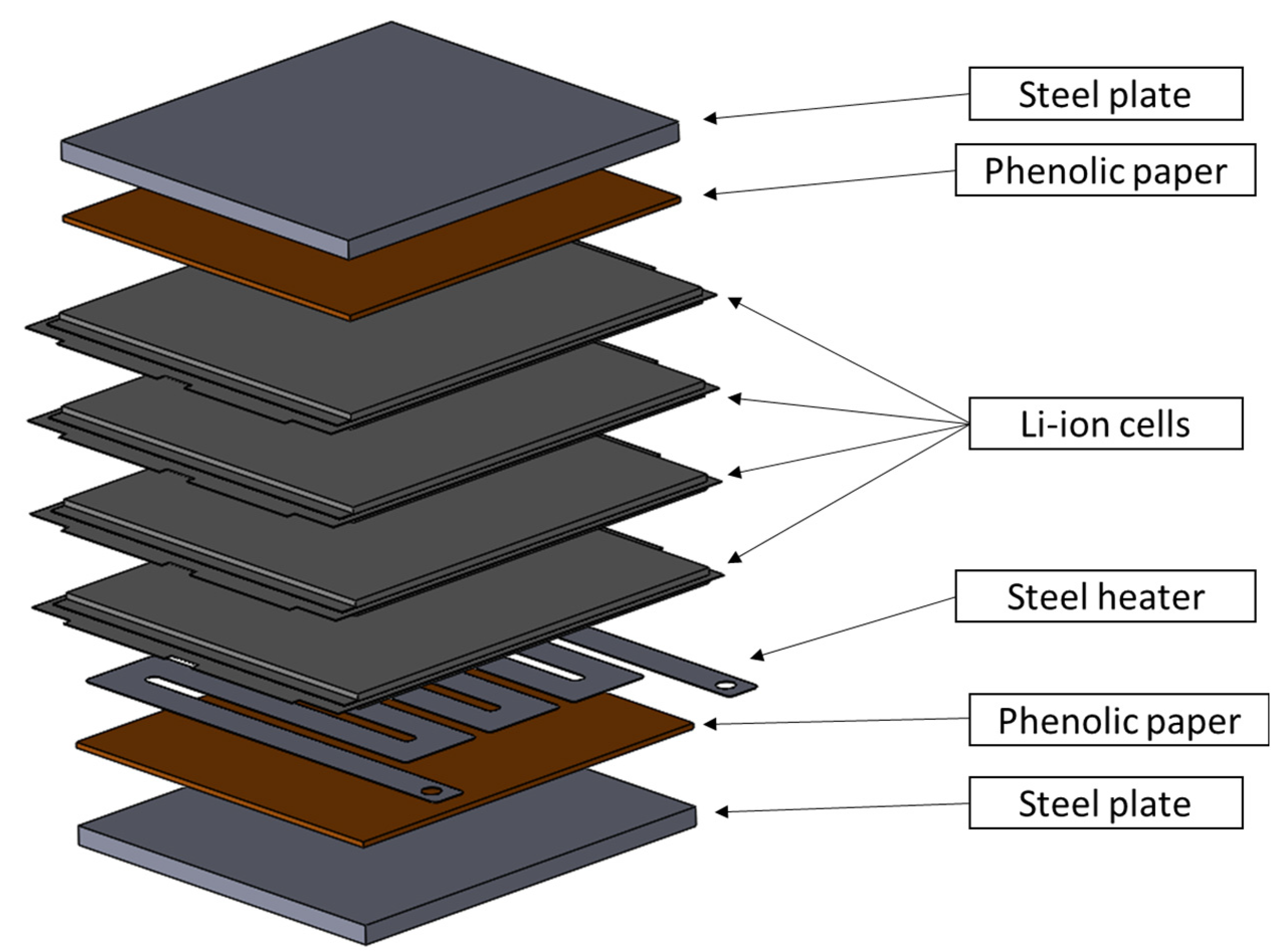
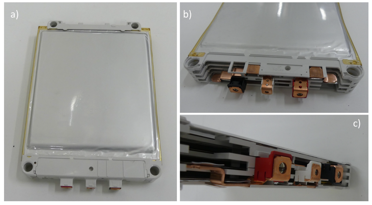
2.1. Samples Description
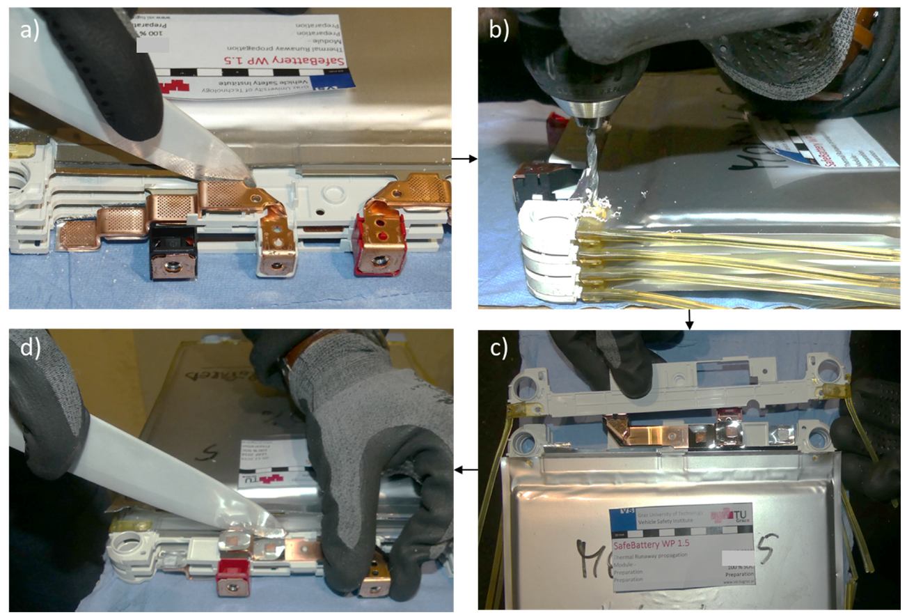
2.2. Samples Preparation
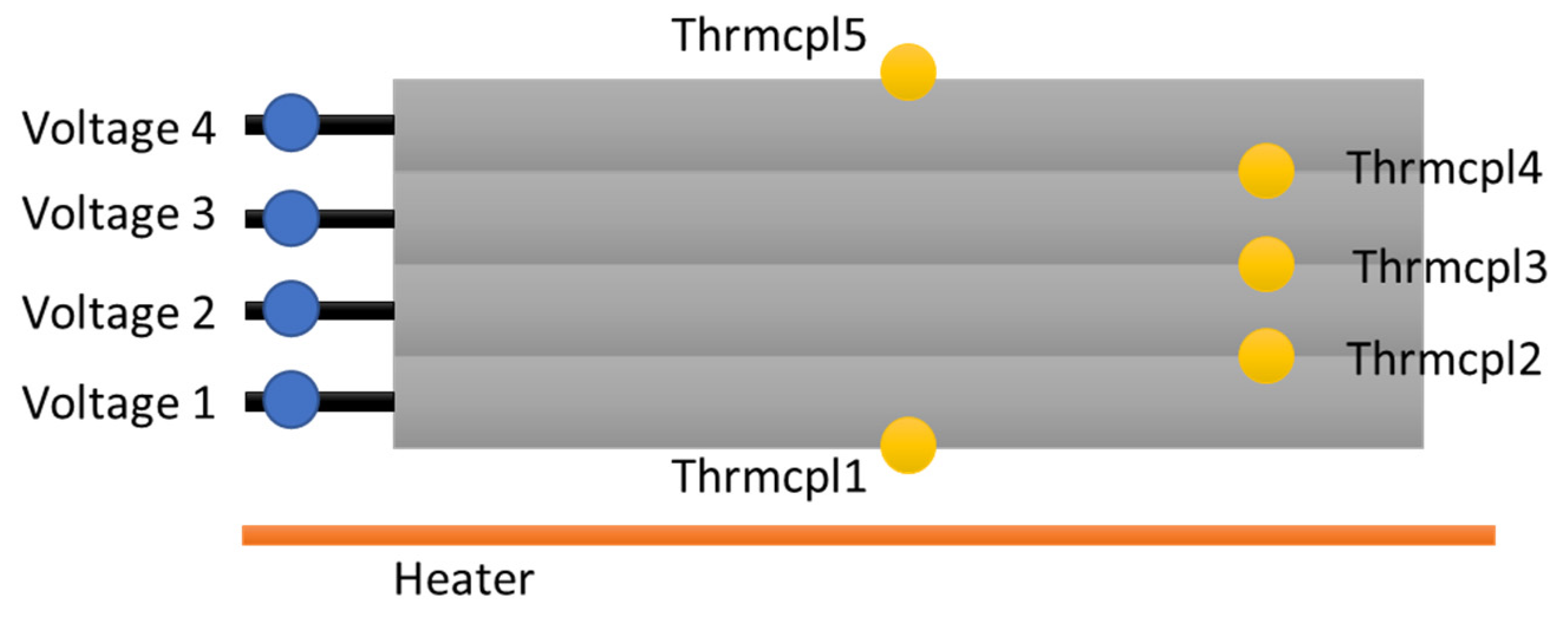
2.3. Equipment and Sensors
2.4. Test Setup and Procedure
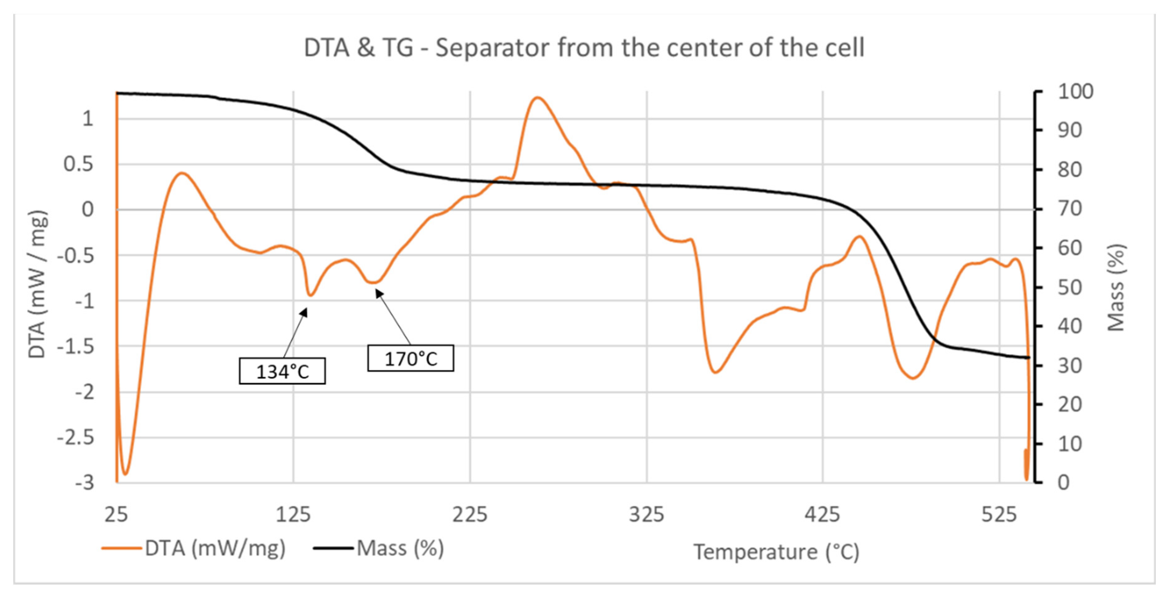
2.5. Analysis of the Separator with Differential Scanning Calorimeter
3. Results
3.1. DSC Analysis of Separator
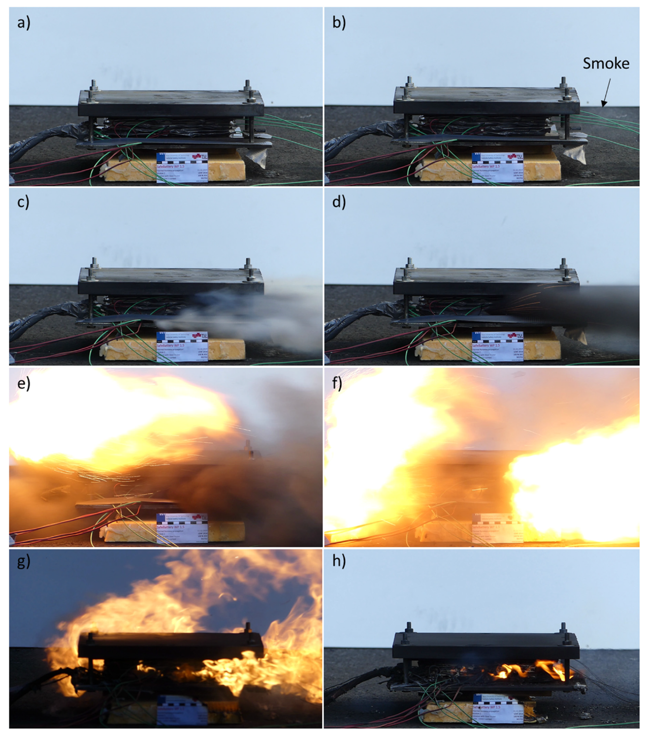
3.2. Observable TR Phases
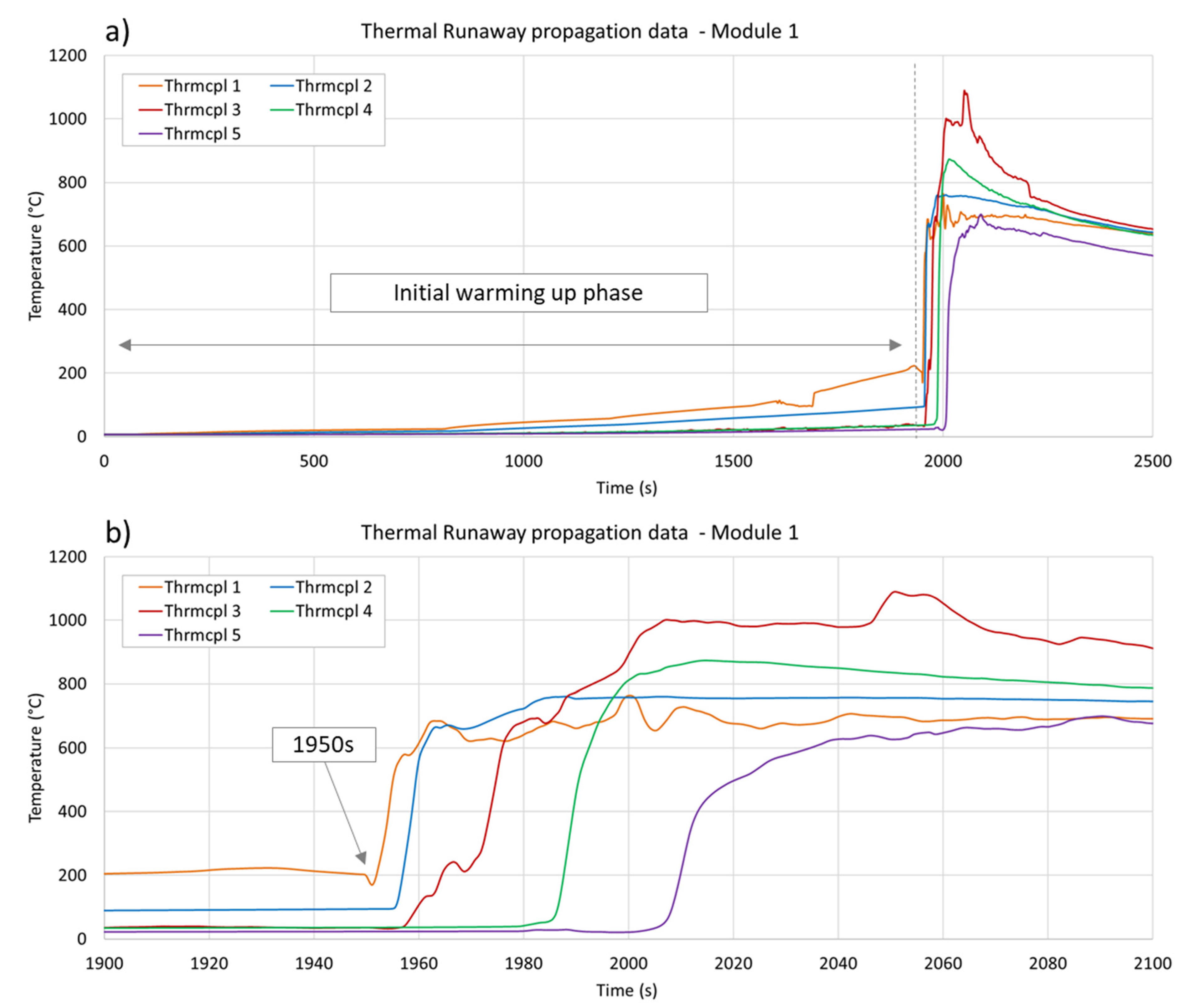
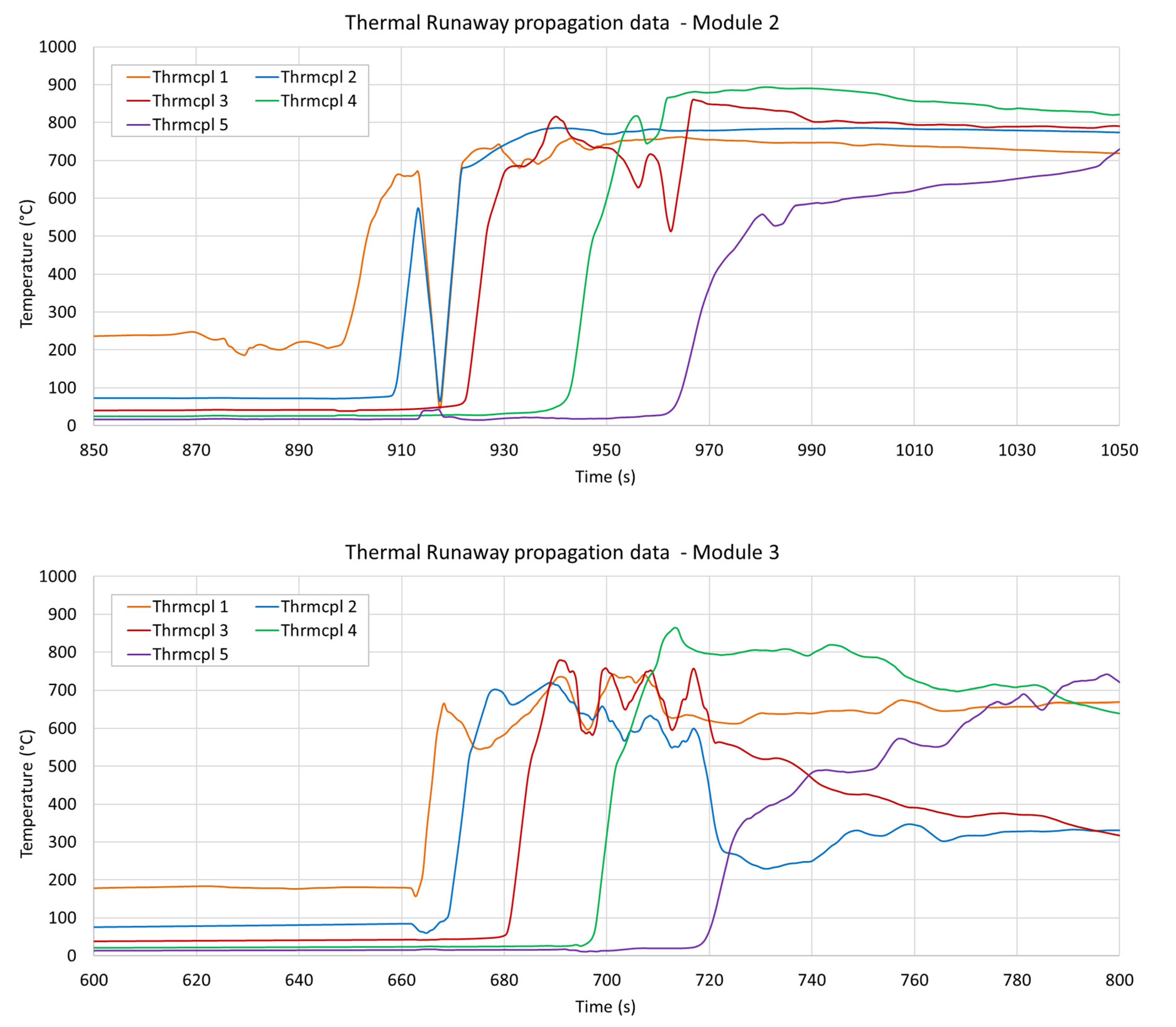
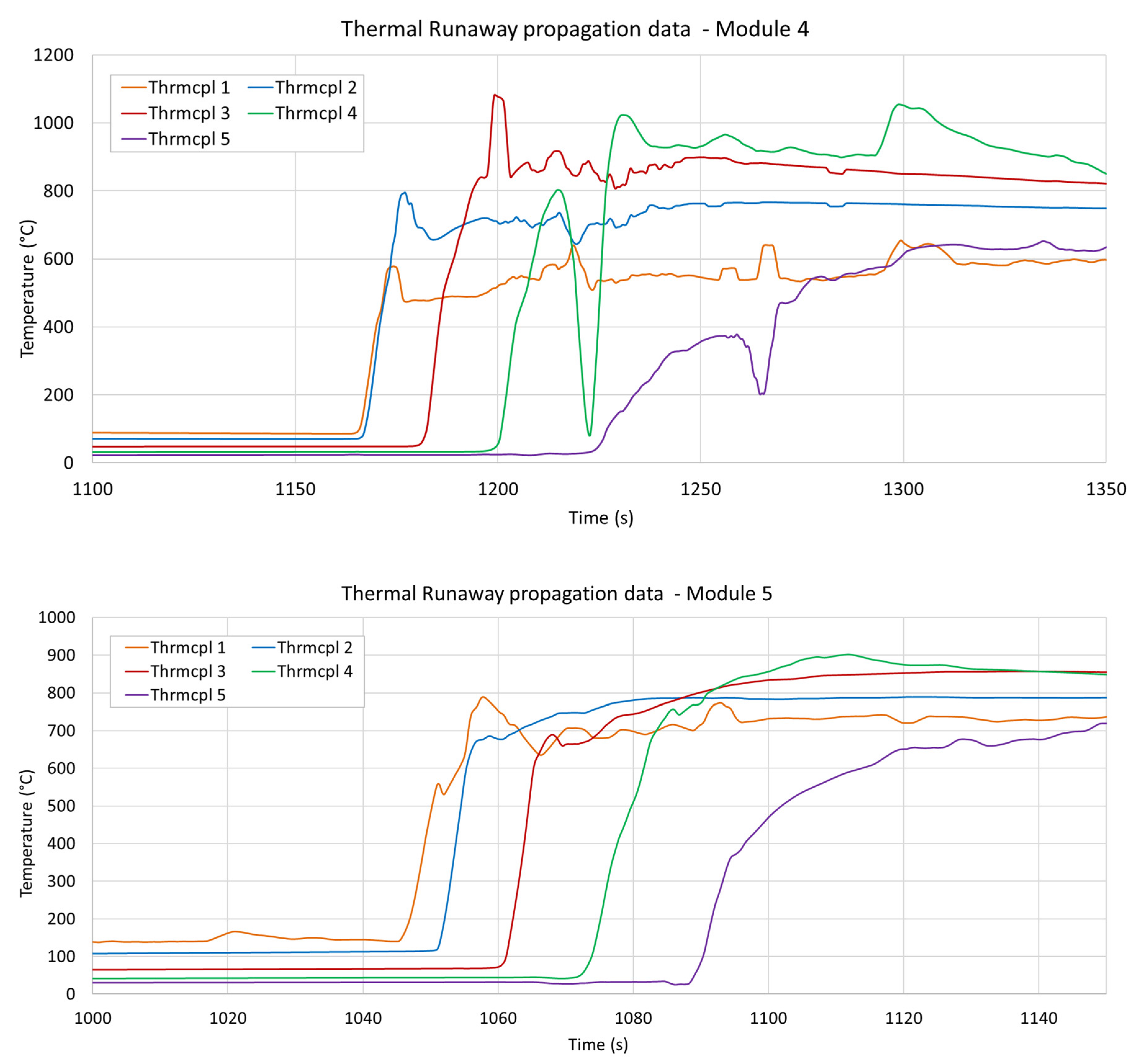
3.3. Temperature Measurements
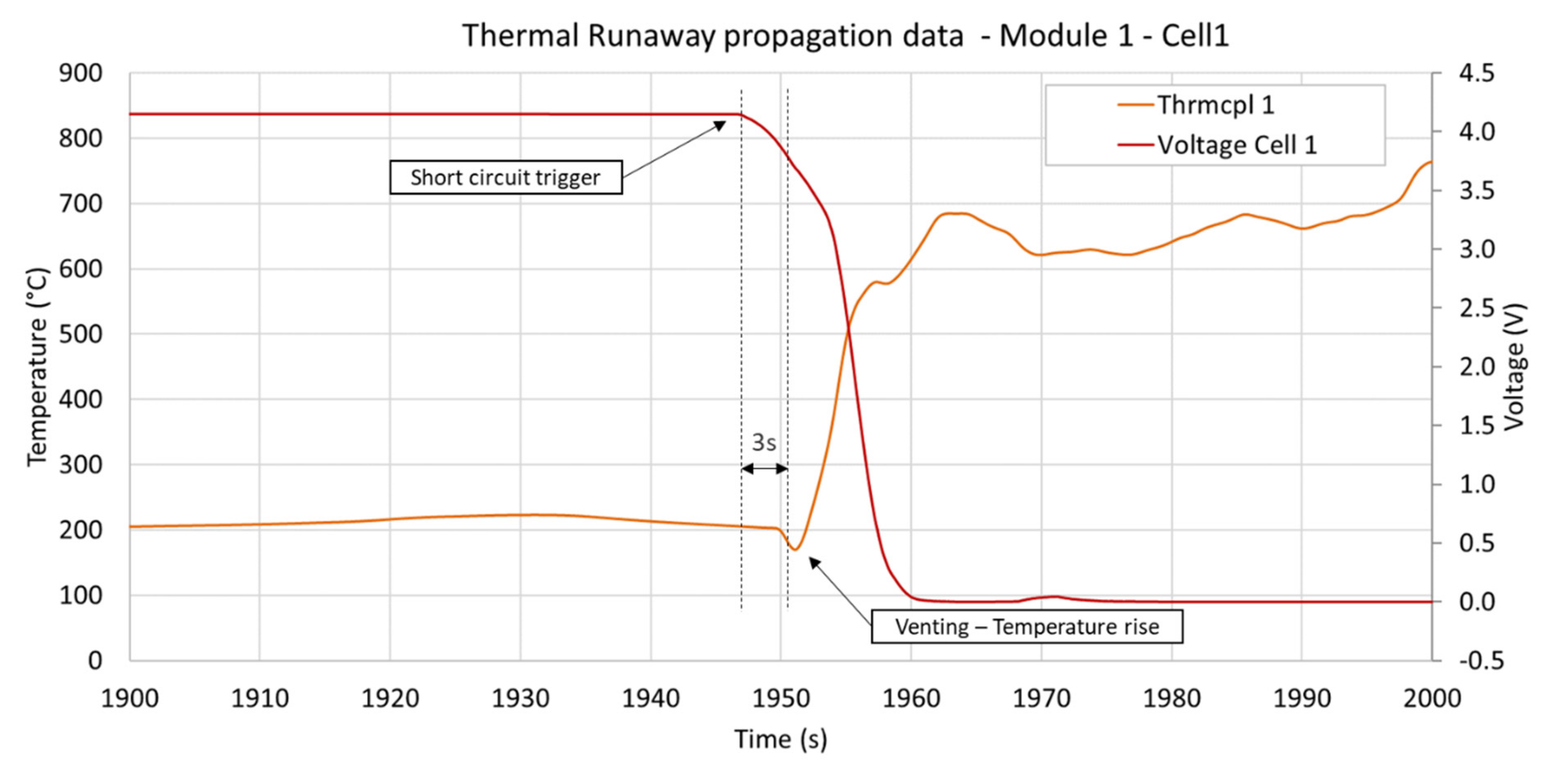
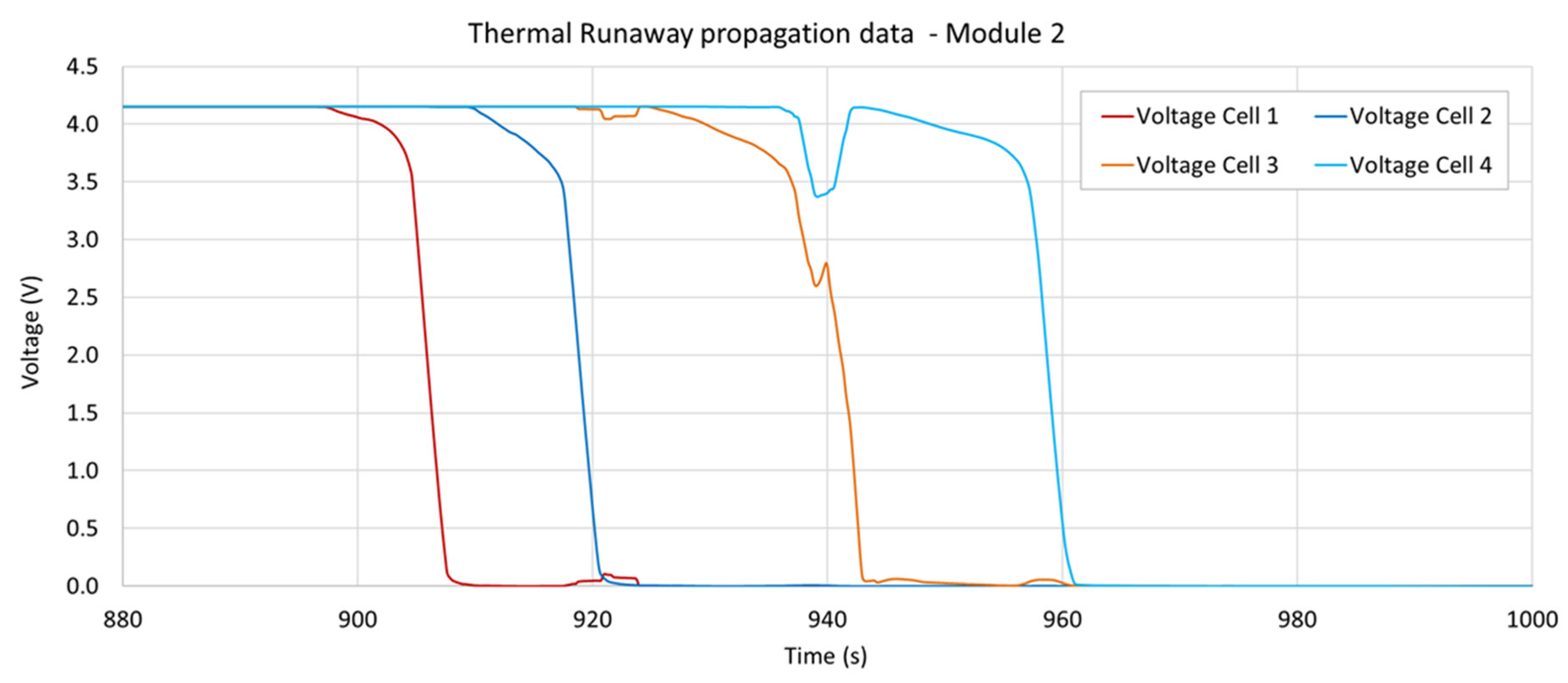
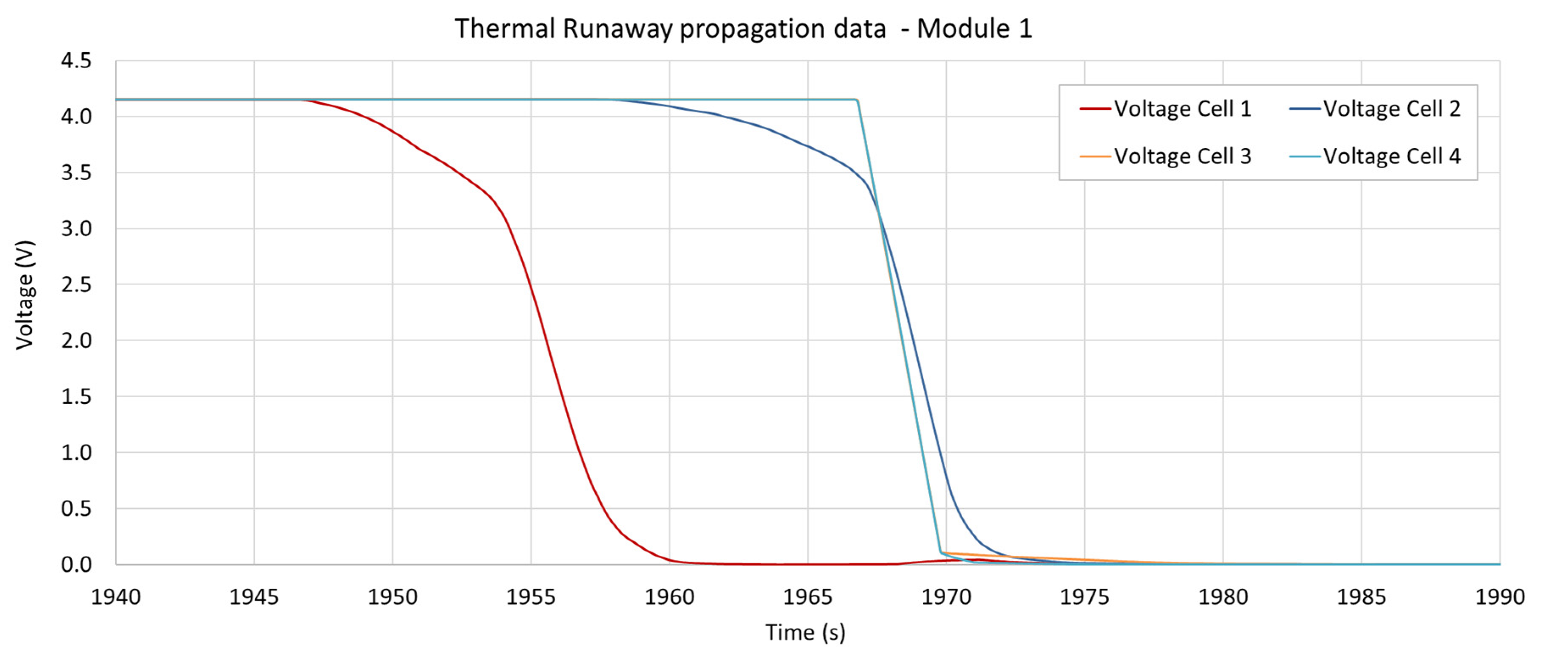
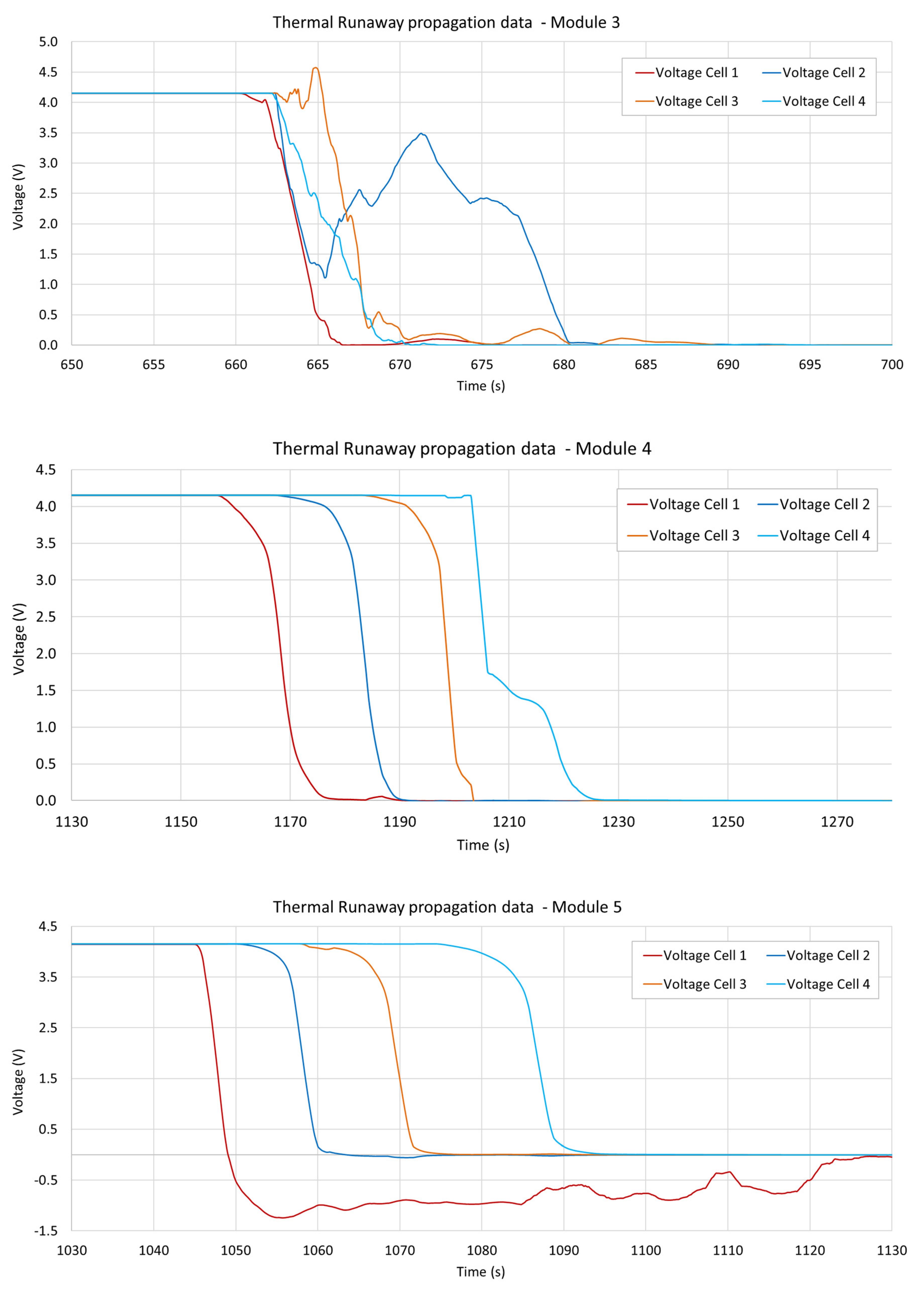
3.4. Voltage Measurements
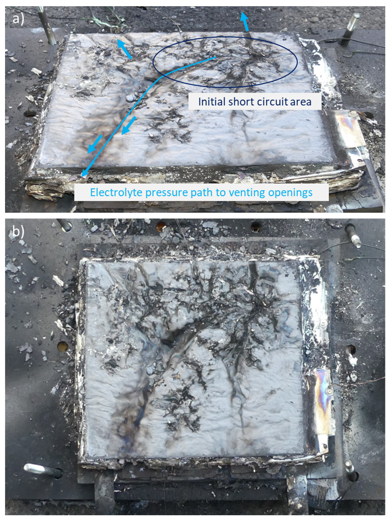
3.5. Postmortem Inspection
4. Results Discussion
5. Conclusions
Author Contributions
Funding
Institutional Review Board Statement
Data Availability Statement
Acknowledgments
Conflicts of Interest
Appendix A


References
- Global Registry. Global Technical Regulation on the Electric Vehicle Safety (EVS), ECE-United Nations. 2018. Available online: https://unece.org/ (accessed on 31 March 2021).
- Baird, A.R.; Archibald, E.J.; Marr, K.C.; Ezekoye, O.A. Explosion hazards from lithium-ion battery vent gas. J. Power Sources 2020, 446, 227257. [Google Scholar] [CrossRef]
- Feng, X.; Zheng, S.; Ren, D.; He, X.; Wang, L.; Cui, H.; Liu, X.; Jin, C.; Zhang, F.; Xu, C.; et al. Investigating the thermal runaway mechanisms of lithium-ion batteries based on thermal analysis database. Appl. Energy 2019, 246, 53–64. [Google Scholar] [CrossRef]
- Feng, X.; Ouyang, M.; Liu, X.; Lu, L.; Xia, Y.; He, X. Thermal runaway mechanism of lithium ion battery for electric vehicles: A review. Energy Storage Mater. 2018, 10, 246–267. [Google Scholar] [CrossRef]
- Lei, B.; Zhao, W.; Ziebert, C.; Uhlmann, N.; Rohde, M.; Seifert, H.J. Experimental Analysis of Thermal Runaway in 18650 Cylindrical Li-Ion Cells Using an Accelerating Rate Calorimeter. Batteries 2017, 3, 14. [Google Scholar] [CrossRef] [Green Version]
- Mao, B.; Huang, P.; Chen, H.; Wang, Q.; Sun, J. Self-heating reaction and thermal runaway criticality of the lithium ion battery. Int. J. Heat Mass Transf. 2020, 149, 119178. [Google Scholar] [CrossRef]
- Mukai, T.; Sakai, T.; Yanagida, M. Thermal Runaway Mechanism and High Safety Technology of Lithium Ion Battery. J. Surf. Finish. Soc. Jpn. 2019, 70, 301–307. [Google Scholar] [CrossRef]
- Zhong, G.; Mao, B.; Wang, C.; Jiang, L.; Xu, K.; Sun, J.; Wang, Q. Thermal runaway and fire behavior investigation of lithium ion batteries using modified cone calorimeter. J. Therm. Anal. Calorim. 2019, 135, 2879–2889. [Google Scholar] [CrossRef]
- Cheng, X.; Li, T.; Ruan, X.; Wang, Z. Thermal Runaway Characteristics of a Large Format Lithium-Ion Battery Module. Energies 2019, 12, 3099. [Google Scholar] [CrossRef] [Green Version]
- Feng, X.; Fang, M.; He, X.; Ouyang, M.; Lu, L.; Wang, H.; Zhang, M. Thermal runaway features of large format prismatic lithium ion battery using extended volume accelerating rate calorimetry. J. Power Sources 2014, 255, 294–301. [Google Scholar] [CrossRef]
- Li, H.; Chen, H.; Zhong, G.; Wang, Y.; Wang, Q. Experimental study on thermal runaway risk of 18650 lithium ion battery under side-heating condition. J. Loss Prev. Process. Ind. 2019, 61, 122–129. [Google Scholar] [CrossRef]
- Wang, Z.; Yang, H.; Li, Y.; Wang, G.; Wang, J. Thermal runaway and fire behaviors of large-scale lithium ion batteries with different heating methods. J. Hazard. Mater. 2019, 379, 120730. [Google Scholar] [CrossRef] [PubMed]
- Kriston, A.; Kersys, A.; Antonelli, A.; Ripplinger, S.; Holmstrom, S.; Trischler, S.; Döring, H.; Pfrang, A. Initiation of thermal runaway in Lithium-ion cells by inductive heating. J. Power Sources 2020, 454, 227914. [Google Scholar] [CrossRef]
- Feng, X.; He, X.; Ouyang, M.; Lu, L.; Wu, P.; Kulp, C.; Prasser, S. Thermal runaway propagation model for designing a safer battery pack with 25Ah LiNixCoyMnzO2 large format lithium ion battery. Appl. Energy 2015, 74–91. [Google Scholar] [CrossRef]
- Huang, P.; Ping, P.; Li, K.; Chen, H.; Wang, Q.; Wen, J.; Sun, J. Experimental and modeling analysis of thermal runaway propagation over the large format energy storage battery module with Li4Ti5O12 anode. Appl. Energy 2016, 183, 659–673. [Google Scholar] [CrossRef]
- Larsson, F.; Anderson, J.; Andersson, P.; Mellander, B.-E. Thermal Modelling of Cell-to-Cell Fire Propagation and Cascading Thermal Runaway Failure Effects for Lithium-Ion Battery Cells and Modules Using Fire Walls. J. Electrochem. Soc. 2016, 163, A2854–A2865. [Google Scholar] [CrossRef]
- Said, A.O.; Lee, C.; Stoliarov, S.I.; Marshall, A.W. Comprehensive analysis of dynamics and hazards associated with cascading failure in 18650 lithium ion cell arrays. Appl. Energy 2019, 248, 415–428. [Google Scholar] [CrossRef]
- Tao, C.; Li, G.; Zhao, J.; Chen, G.; Wang, Z.; Qian, Y.; Cheng, X.; Liu, X. The investigation of thermal runaway propagation of lithium-ion batteries under different vertical distances. J. Therm. Anal. Calorim. 2020, 155, 401. [Google Scholar] [CrossRef]
- Wang, Z.; Mao, N.; Jiang, F. Study on the effect of spacing on thermal runaway propagation for lithium-ion batteries. J. Therm. Anal. Calorim. 2019, 10, 430. [Google Scholar] [CrossRef]
- Sun, L.; Wei, C.; Guo, D.; Liu, J.; Zhao, Z.; Zheng, Z.; Jin, Y. Comparative Study on Thermal Runaway Characteristics of Lithium Iron Phosphate Battery Modules Under Different Overcharge Conditions. Fire Technol. 2020, 3, 43. [Google Scholar] [CrossRef]
- Huang, L.; Zhang, Z.; Wang, Z.; Zhang, L.; Zhu, X.; Dorrell, D.D. Thermal runaway behavior during overcharge for large-format Lithium-ion batteries with different packaging patterns. J. Energy Storage 2019, 25, 100811. [Google Scholar] [CrossRef]
- Wang, Z.; Liu, K.; Liu, J.; Luo, Q.; Ma, C. Influence of the charging and discharging of the 18650 lithium-ion battery thermal runaway. J. Loss Prev. Process. Ind. 2017. [Google Scholar] [CrossRef]
- Ma, X.; Zhu, C.; Xie, Z.; Xie, C.; Wang, W.; Zheng, J.; Mu, D.; Wu, B. Progress in Thermal Modeling for Lithium-ion Battery. DEStech Trans. Environ. Energy Earth Sci. 2019. [Google Scholar] [CrossRef]
- Gao, T.; Wang, Z.; Chen, S.; Guo, L. Hazardous characteristics of charge and discharge of lithium-ion batteries under adiabatic environment and hot environment. Int. J. Heat Mass Transf. 2019, 141, 419–431. [Google Scholar] [CrossRef]
- Liu, X.; Stoliarov, S.I.; Denlinger, M.; Masias, A.; Snyder, K. Comprehensive calorimetry of the thermally-induced failure of a lithium ion battery. J. Power Sources 2015, 280, 516–525. [Google Scholar] [CrossRef]
- Golubkov, A.W.; Scheikl, S.; Planteu, R.; Voitic, G.; Wiltsche, H.; Stangl, C.; Fauler, G.; Thaler, A.; Hacker, V. Thermal runaway of commercial 18650 Li-ion batteries with LFP and NCA cathodes—Impact of state of charge and overcharge. RSC Adv. 2015, 5, 57171–57186. [Google Scholar] [CrossRef] [Green Version]
- Spotnitz, R.M.; Franklin, J. Abuse behavior of high-power, lithium-ion cells. J. Power Sources 2003, 113, 81–100. [Google Scholar] [CrossRef]
- Kovachev, G.; Schröttner, H.; Gstrein, G.; Aiello, L.; Hanzu, I.; Wilkening, H.M.R.; Foitzik, A.; Wellm, M.; Sinz, W.; Ellersdorfer, C. Analytical Dissection of an Automotive Li-Ion Pouch Cell. Batteries 2019, 5, 67. [Google Scholar] [CrossRef] [Green Version]


| Observable Phenomena | Temperature Range (External) | |
|---|---|---|
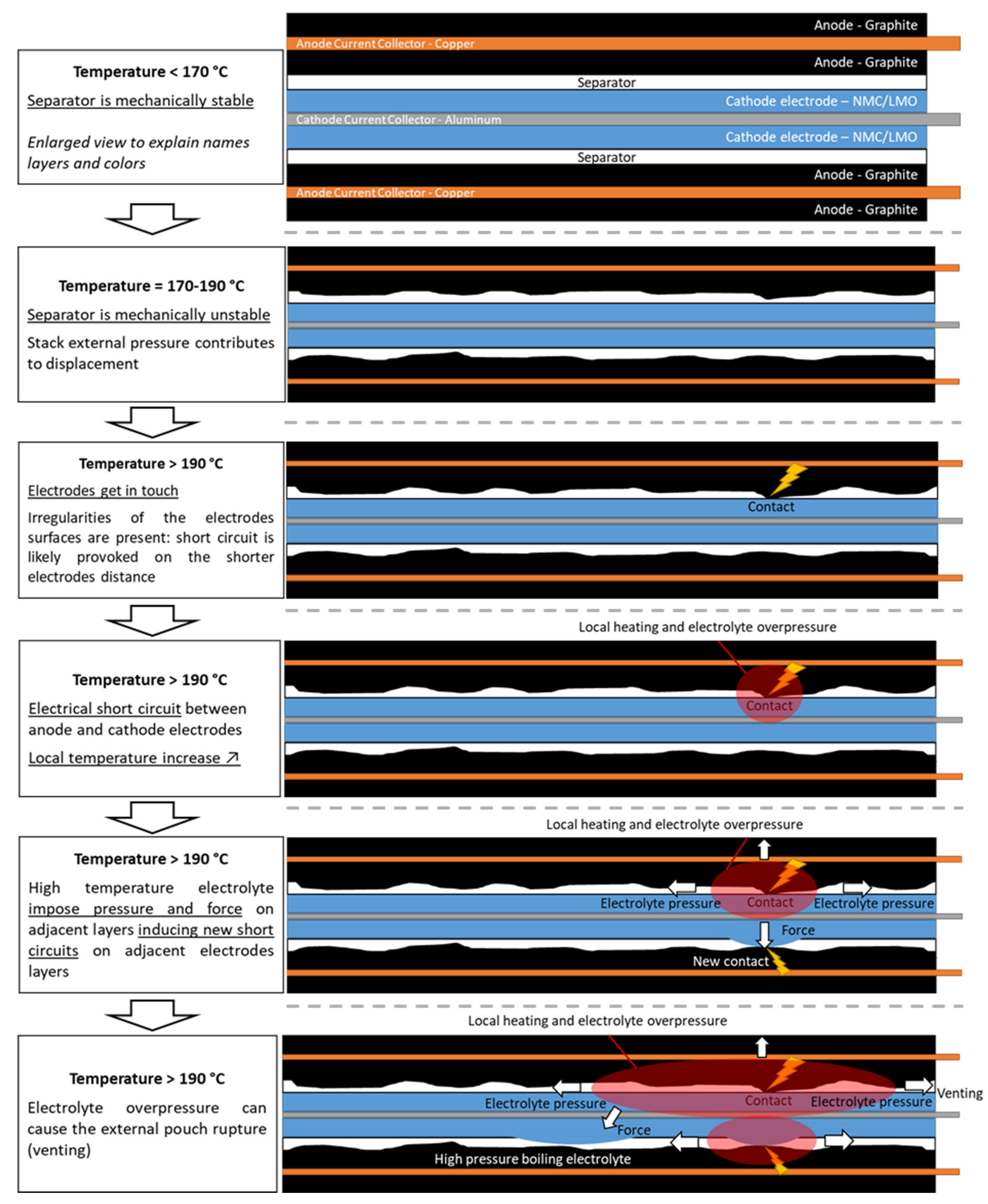
| Phase 1 | No visible effect | <170 °C |
| Phase 2 | Slight smoke release, possible electrolyte leakage, impulsive and discontinuous increase of internal pressure | 170–190 °C |
| Phase 3 | Fast swelling, fast increase of internal pressure and temperature | 190–220 °C |
| Phase 4 | Pouch bag opens, gas venting, decrease of internal pressure, decompression could cause instantaneous temperature drop | >220 °C |
| Phase 5 | Gas venting, sparks initiate the combustion of vented gas | >220 °C |
| Phase 6 | Deep short circuit and gas combustion, triggering of next cells | - |
| Phase 7 | Rise of temperature and pressure is over, system starts to decrease its temperature, uncombusted materials are still present | - |
| Phase 8 | All active materials are combusted, system cools down slowly | - |
| TR Triggering Propagation Time—Based on Voltage Drops | ||||
|---|---|---|---|---|
| Cell 1 | Cell 2 | Cell 3 | Cell 4 | |
| Module 1 | 1947.4 s | 1958.8 s (+11.4) | LoC | LoC |
| Module 2 | 897.9 s | 909.9 s (+12.0) | 924.4 s (+14.5) | 941.9 s (+17.5) |
| Module 3 | 660.5 s | LoC | LoC | LoC |
| Module 4 | 1157.4 s | 1168.3 s (+10.9) | 1184.4 s (+16.1) | 1203.1 s (+18.7) |
| Module 5 | 1045.3 s | 1051.1 s (+5.8) | 1062.3 s (+11.2) | 1075.0 s (+12.7) |
Publisher’s Note: MDPI stays neutral with regard to jurisdictional claims in published maps and institutional affiliations. |
© 2021 by the authors. Licensee MDPI, Basel, Switzerland. This article is an open access article distributed under the terms and conditions of the Creative Commons Attribution (CC BY) license (https://creativecommons.org/licenses/by/4.0/).
Share and Cite
Aiello, L.; Hanzu, I.; Gstrein, G.; Ewert, E.; Ellersdorfer, C.; Sinz, W. Analysis and Investigation of Thermal Runaway Propagation for a Mechanically Constrained Lithium-Ion Pouch Cell Module. Batteries 2021, 7, 49. https://0-doi-org.brum.beds.ac.uk/10.3390/batteries7030049
Aiello L, Hanzu I, Gstrein G, Ewert E, Ellersdorfer C, Sinz W. Analysis and Investigation of Thermal Runaway Propagation for a Mechanically Constrained Lithium-Ion Pouch Cell Module. Batteries. 2021; 7(3):49. https://0-doi-org.brum.beds.ac.uk/10.3390/batteries7030049
Chicago/Turabian StyleAiello, Luigi, Ilie Hanzu, Gregor Gstrein, Eduard Ewert, Christian Ellersdorfer, and Wolfgang Sinz. 2021. "Analysis and Investigation of Thermal Runaway Propagation for a Mechanically Constrained Lithium-Ion Pouch Cell Module" Batteries 7, no. 3: 49. https://0-doi-org.brum.beds.ac.uk/10.3390/batteries7030049