
Current Developments and Challenges in the Recycling of Key Components of (Hybrid) Electric Vehicles

Abstract
:1. Introduction
2. Background
2.1. Key Components of (H)EVs
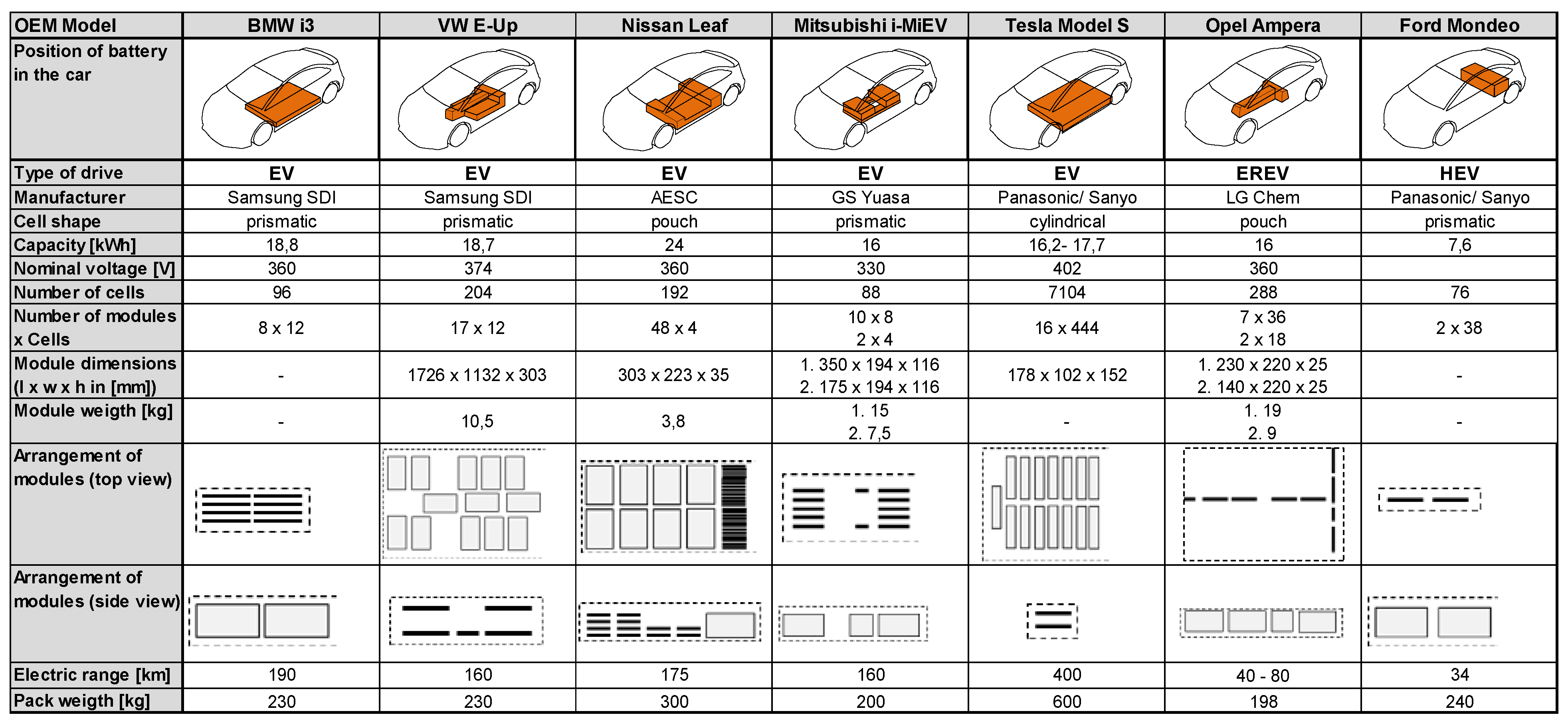
2.1.1. Traction Batteries

Nickel-Metal Hydride Cells
Lithium Ion Cells
Cathode Materials

| Material | Capacity (Ah/kg) | Operating Voltage (V) | Energy Density (Wh/kg) |
|---|---|---|---|
| NCA (LiNi0.8Co0.15Al0.05O2) | 200 | 3.7 | 740 |
| LCO (LiCoO2) | 160 | 3.9 | 624 |
| NMC (LiNi0.33Mn0.33Co0.33O2) | 160 | 3.7 | 592 |
| LMO (LiMn2O4) | 100 | 4.1 | 410 |
| LFP (LiFePO4) | 160 | 3.4 | 544 |
Anode Materials
Electrolytes and Separators
Battery Management System and Thermal Management
Material Compositions of Traction Batteries
| Cell type | NMC | NCA | LFP |
|---|---|---|---|
| Battery Cells | |||
| Total | 630 | 598 | 530 |
| Active cathode material | 191 | 175 | 173 |
| Lithium | 14 | 13 | 7.6 |
| Cobalt | 39 | 16 | 0 |
| Nickel | 39 | 86 | 0 |
| Manganese | 36 | 0 | 0 |
| Aluminum | 0 | 2.5 | 0 |
| Iron | 0 | 0 | 61 |
| Phosphorus | 0 | 0 | 34 |
| Oxygen | 63 | 58 | 70 |
| Cathode foil (aluminum) | 39 | 40 | 34 |
| Electrolyte | 114 | 101 | 85 |
| Separator | 54 | 50 | 43 |
| Active anode material (carbon) | 140 | 131 | 111 |
| Anode foil (copper) | 66 | 70 | 60 |
| Cell casing (aluminum) | 21 | 20 | 17 |
| Others | 6 | 10 | 8.5 |
| Total | 370 | 402 | 470 |
| Wiring | 21 | 50 | 64 |
| Copper | 13 | 30 | 38 |
| Battery Infrastructure | |||
| Aluminum | 1.4 | 10 | 13 |
| Stainless steel | 7 | 10 | 13 |
| Frame & Casing | 313 | 342 | 395 |
| Plastics | 107 | 81 | 102 |
| Stainless steel | 206 | 261 | 293 |
| Others (including BMS) | 36 | 10 | 11 |
2.1.2. Electric Drive Motors
| (H)EV | Sales | Type | Motor Type |
|---|---|---|---|
| Nissan LEAF | 30200 | EV | PM [22] |
| Chevrolet Volt | 18805 | HEV | PM [23] |
| Tesla Model S * | 17300 | EV | IM [24] |
| Toyota Prius PHV | 13264 | HEV | PM [25] |
| Ford Fusion Energi | 11550 | HEV | PM [26] |
| Ford C-Max Energi | 8433 | HEV | PM [26] |
| BMW i3 ** | 6092 | EV/HEV | PM [24] |
| smart ED | 2594 | EV | PM [22] |
| Ford Focus Electric | 1964 | EV | PM [25] |
| Fiat 500e * | 1793 | EV | IM [22] |
| Cadillac ELR | 1310 | HEV | PM [23] |
| Toyota RAV4 EV | 1184 | EV | IM [24] |
| Chevrolet Spark EV | 1145 | EV | PM [27] |
| Total | 119710 | ||
| Worldwide | 320713 |
| Material | PM-Motor in EVs; 80 kW | PM-Motor in HEVs; 20 kW |
|---|---|---|
| (kg) | (kg) | |
| Steel | 34.8 | 23.1 |
| Aluminum | 14.1 | 4.7 |
| Magnets | 2.1 | 1.4 |
| Cast Iron | 3.0 | 0 |
| Copper | 8.5 | 6.4 |
| Polymers | 0 | 0.6 |
| Elastomers | 0 | 0.1 |
| Liquids | 0 | 7.7 |
| In Total | 62.5 | 44.0 |
2.1.3. Power Electronics
- The inverter converts the direct current of the battery to alternating current (AC) for operation of the electric motor.
- The DC voltage converter supplies the on-board electrical system (low volt auxiliary consumers) with low voltages.
- Some vehicle concepts also foresee an additional DC converter which converts the battery voltage to a higher voltage before converting it to AC for the electric motor by a downstream inverter.
- The power electronics also comprises printed circuit boards with control electronics.
- Additionally, an onboard-charger with an AC-DC converter is used in BEV and PHEV as a link between the external grid and battery.
- Casing and cooling (mainly aluminum) (50%–60%)
- Power semiconductor module board (1.5%–3%)
- Several printed circuit boards with small electronic components (5%–7%)
- Large capacitors (mainly film capacitors) (7%–20%)
- Inductors (5%–10%)
- Mounting material, wiring, others (15%–25%)
| Element | Average Content |
|---|---|
| Cu | 33.1% |
| Au | 313 ppm |
| Ag | 625 ppm |
| Pd | 31 ppm |
| Ta | 0.29% |
| Sb | 157 ppm |
| Sn | 0.93% |
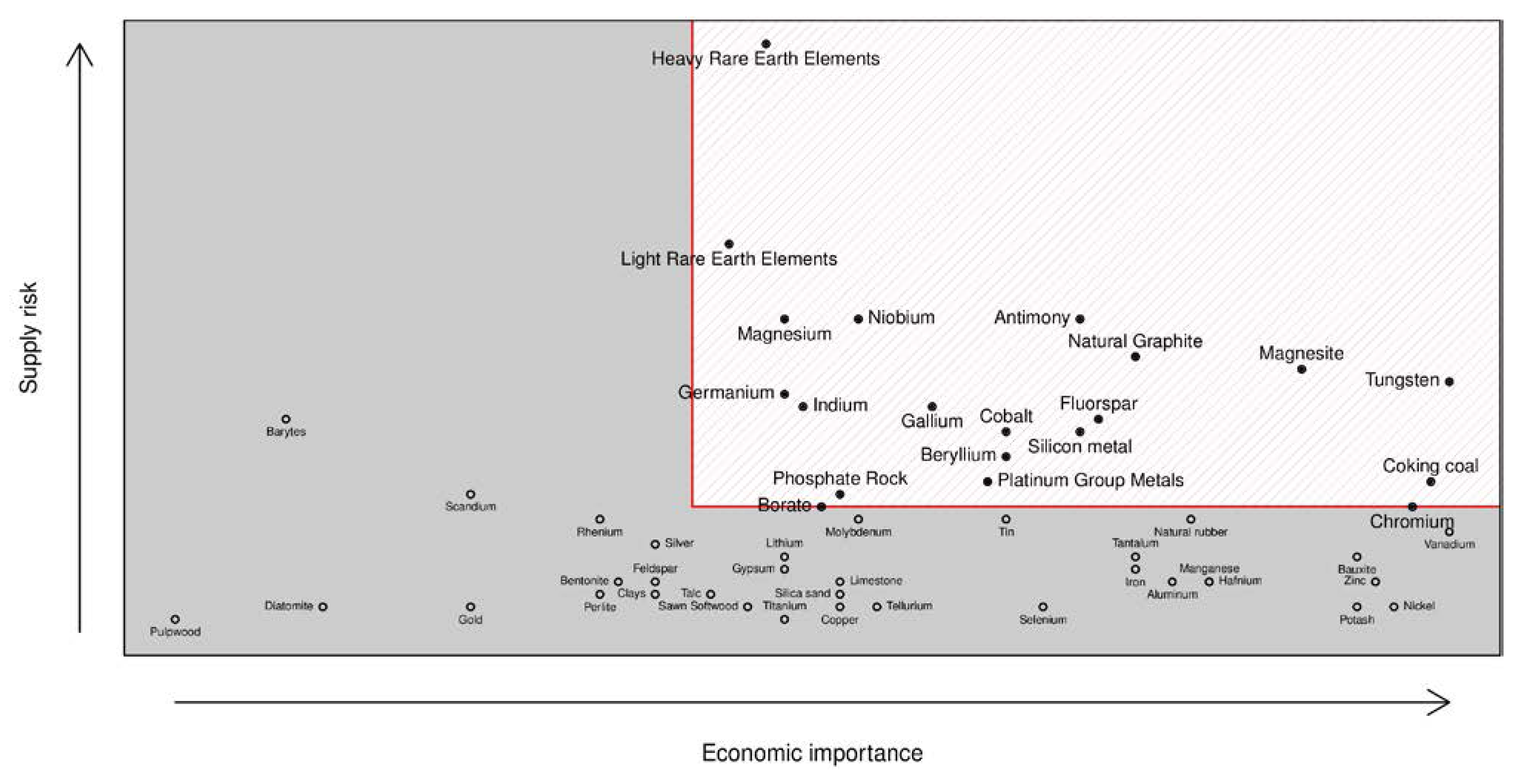
2.2. Criticality of Raw Materials

2.3. Legal Framework in the European Union
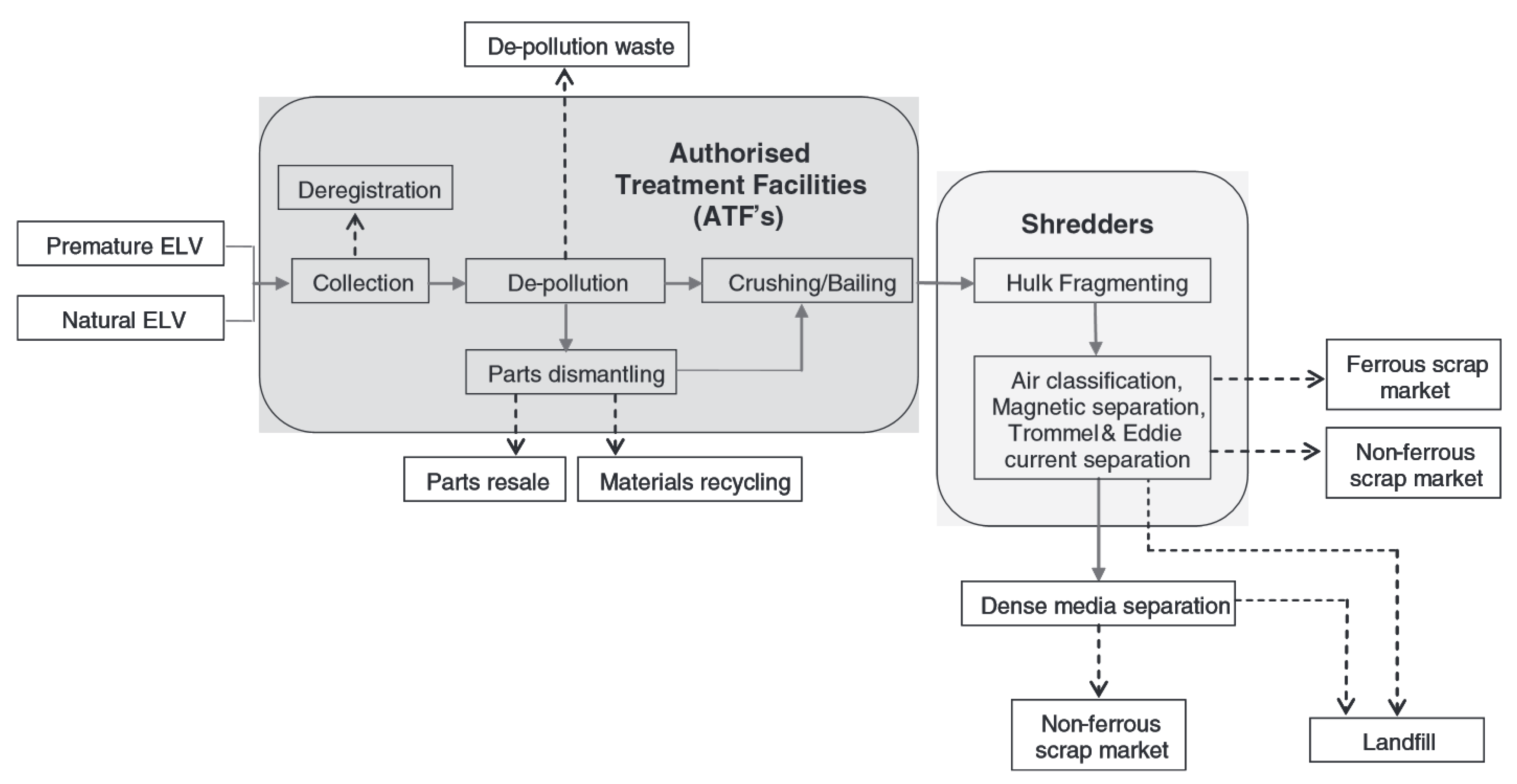
2.4. State-of-the-Art Vehicle Recycling

3. Necessary Changes in the Pretreatment of End-of-Life Vehicles through Electromobility
3.1. Disassembly of Traction Batteries
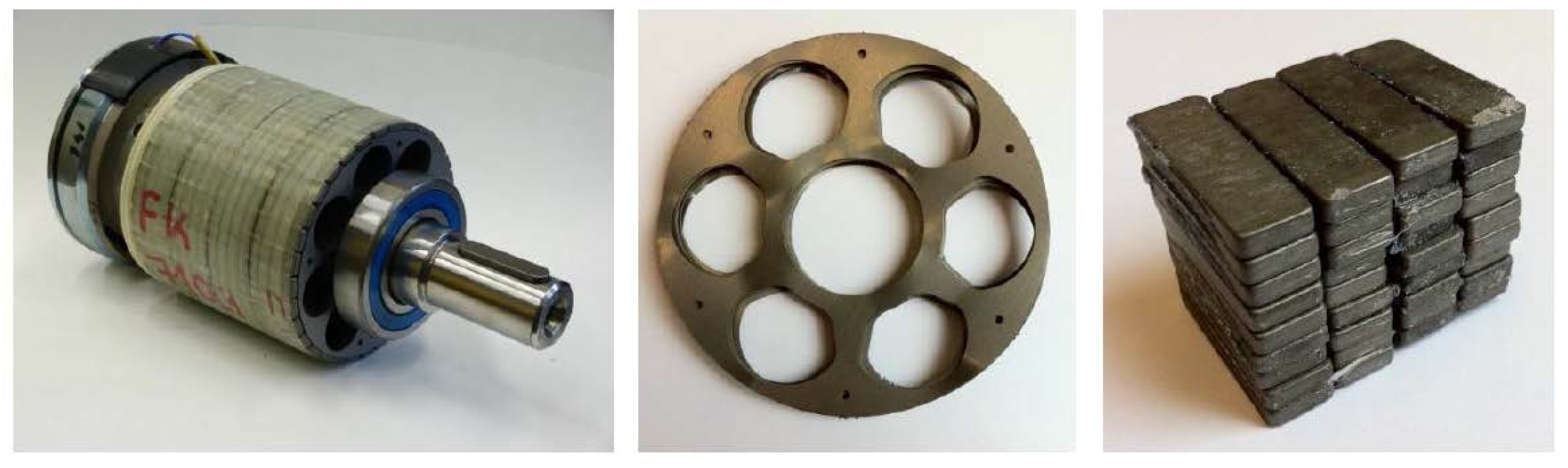
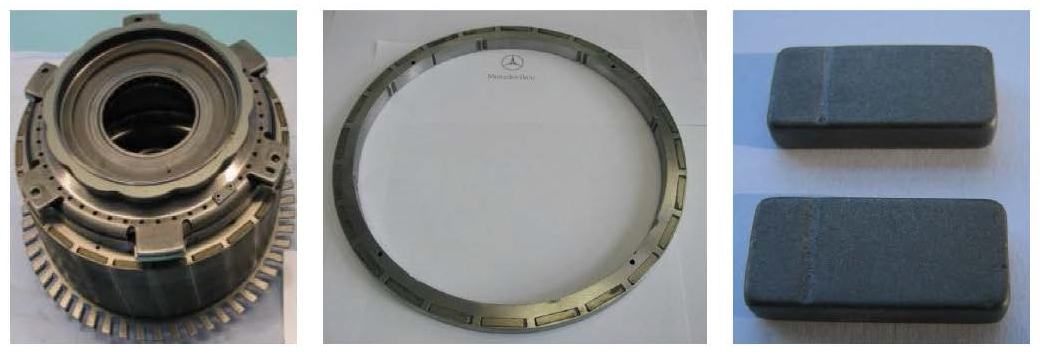
3.2. Disassembly of Electric Motors
3.3. Disassembly of Power Electronics
4. Selected Recycling Processes for Traction Batteries, Electric Drive Motors and Power Electronics
4.1. Traction Batteries
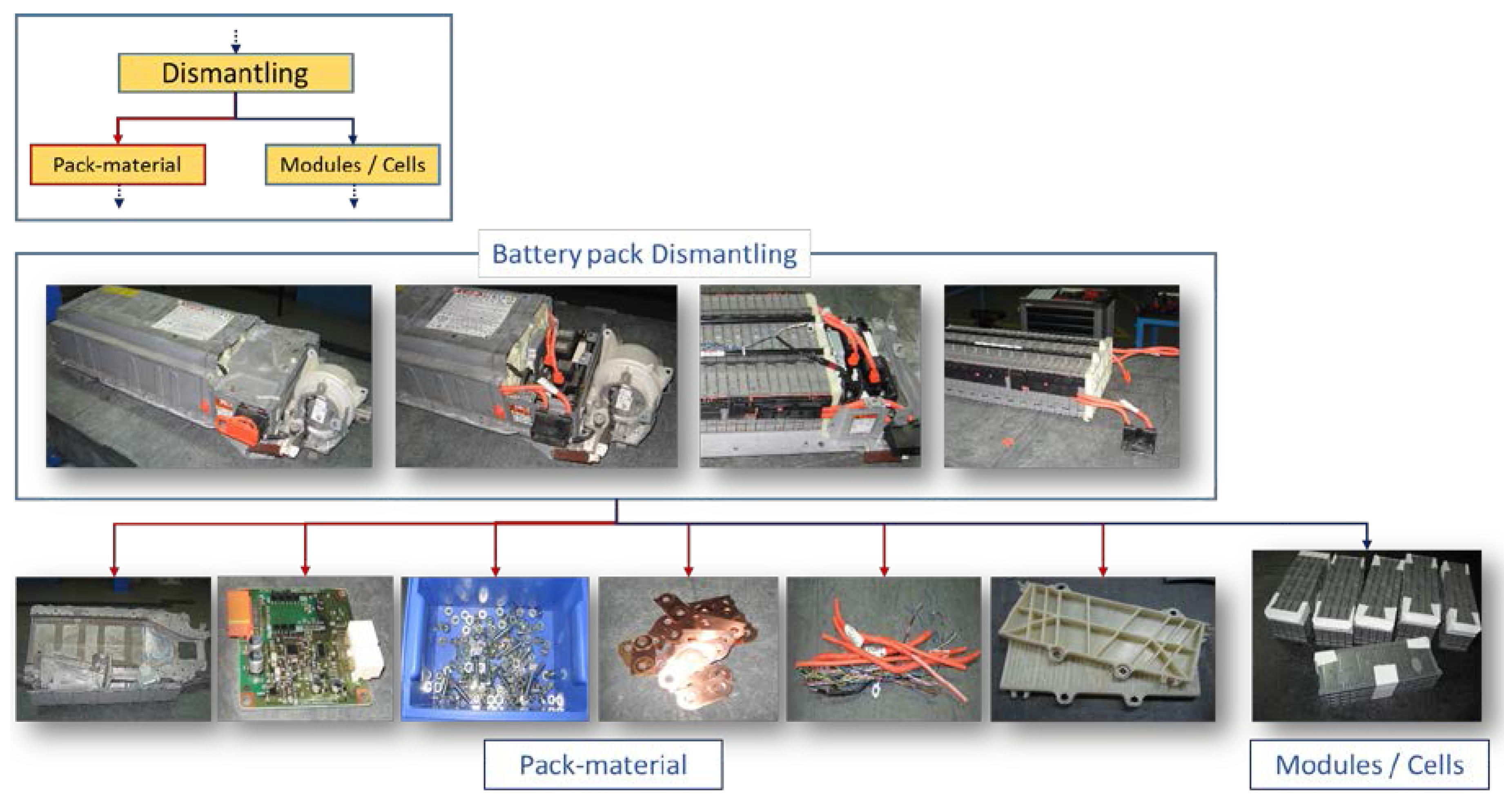
4.1.1. Dismantling

4.1.2. Battery Cell Recycling Processes
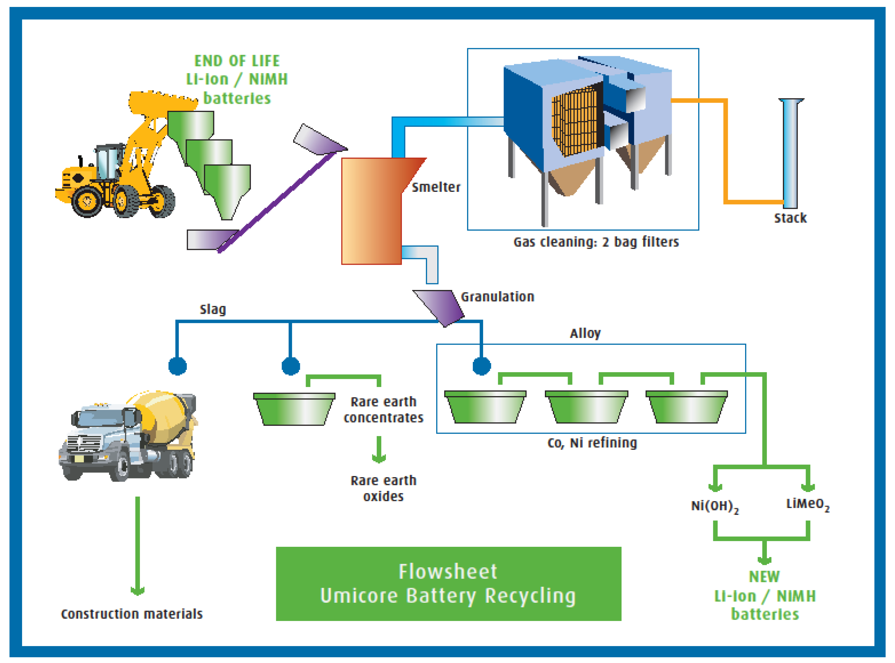
Umicore Battery Recycling Process

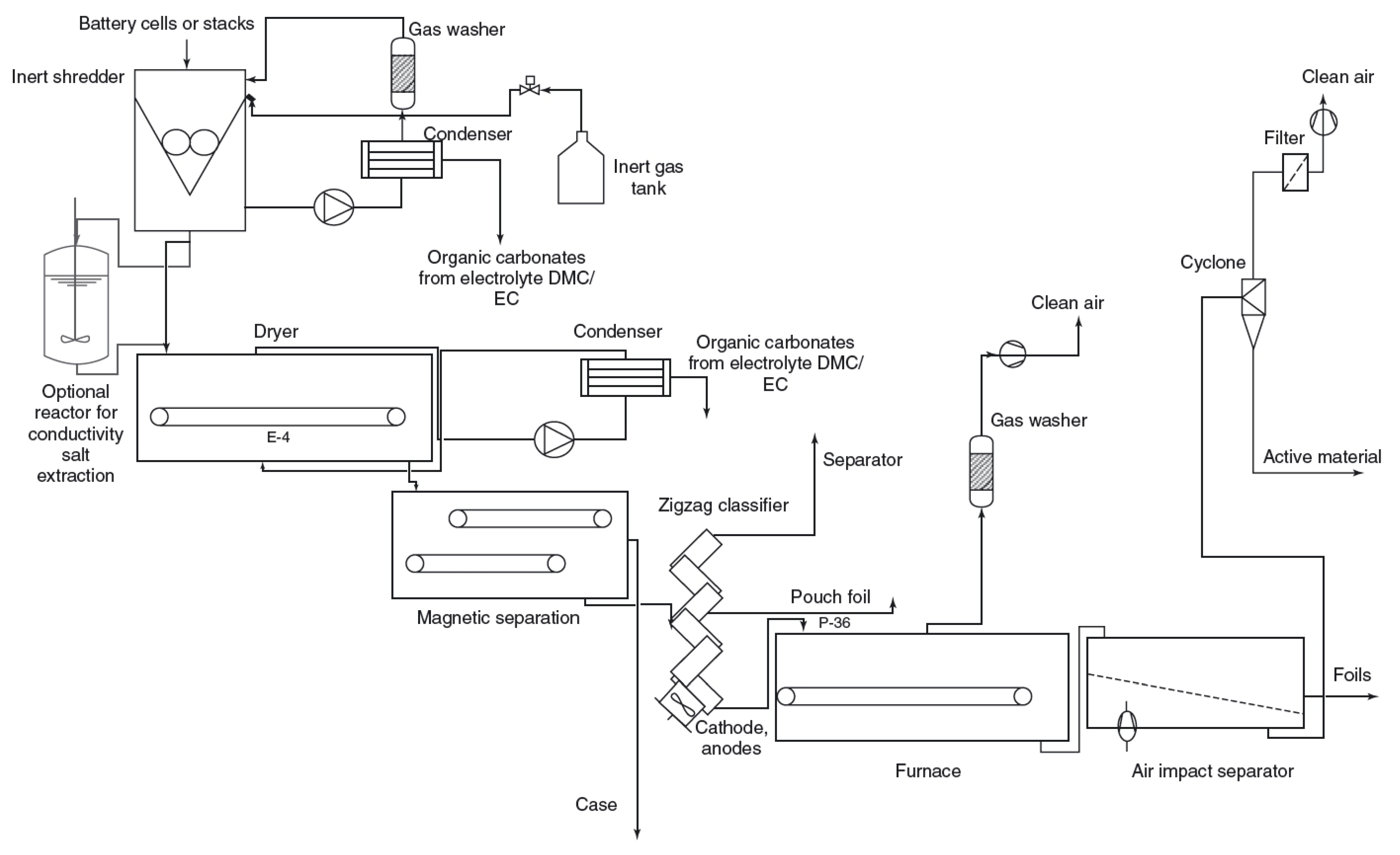
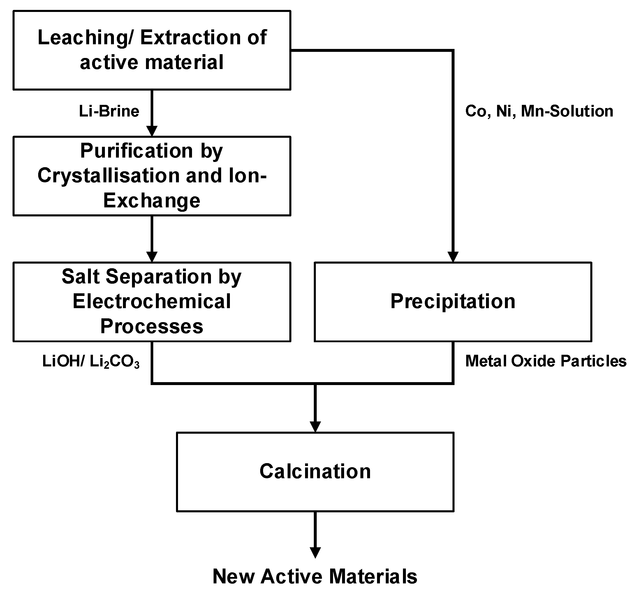
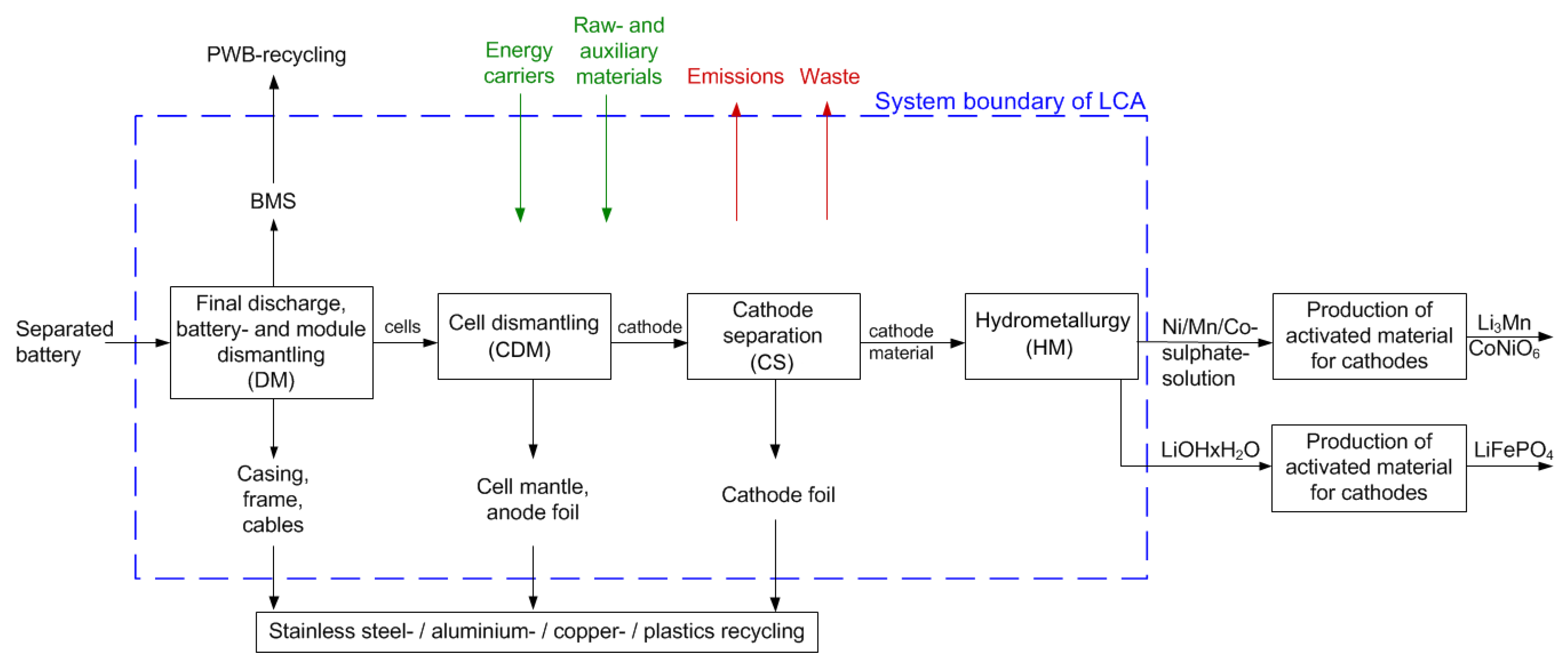
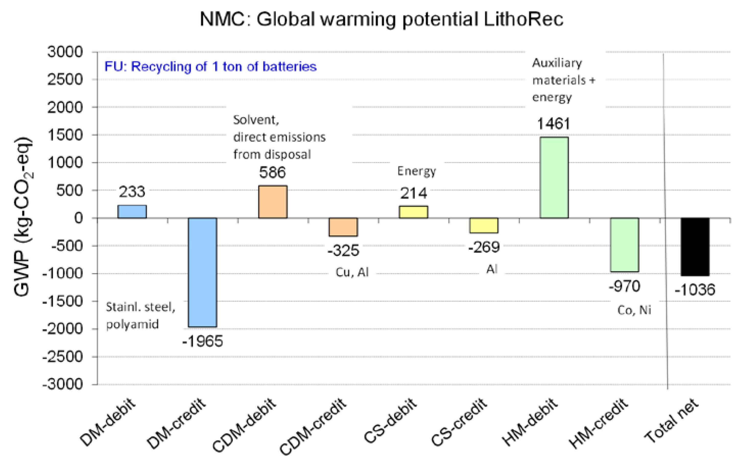
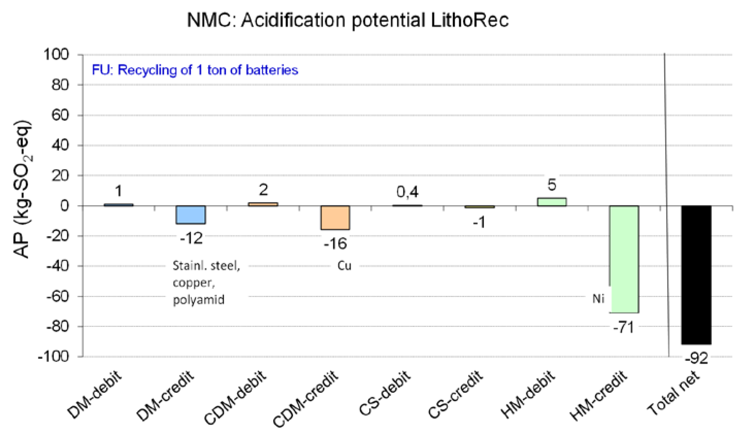
LithoRec Process


- Suitable starting material for cathode production (Co-/Ni-/MnSO4 in mixed dilution, LiOH)
- Further valuable products (Cu, Al, stainless steel, plastics) from the battery casing, etc.


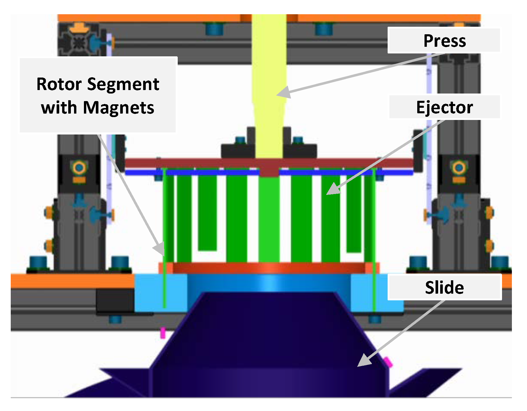
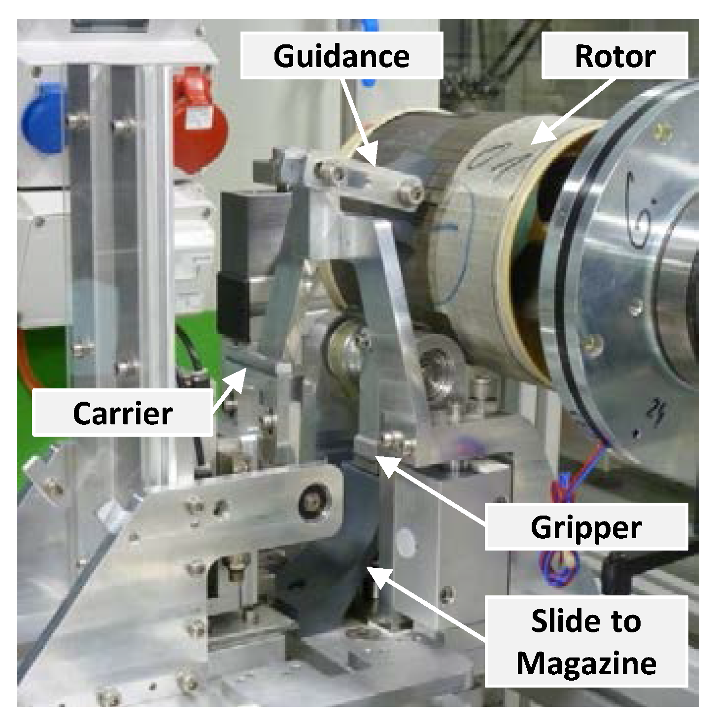
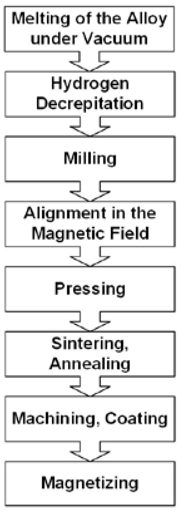
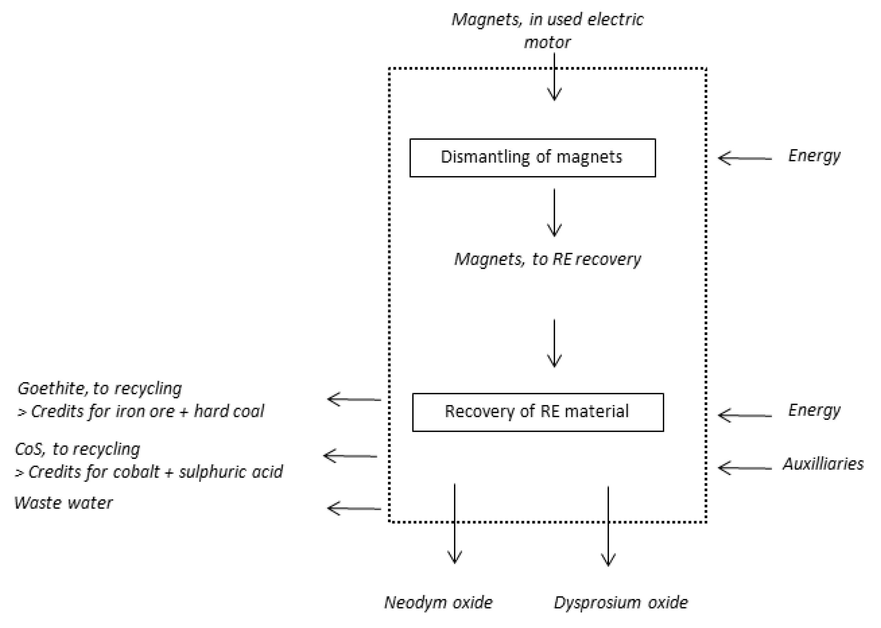
4.2. Electric Drive Motors


| Element | Mass Percentage |
|---|---|
| Fe | 67 |
| B | 1 |
| Co | 2 |
| Nd | 20 |
| Dy | 10 |
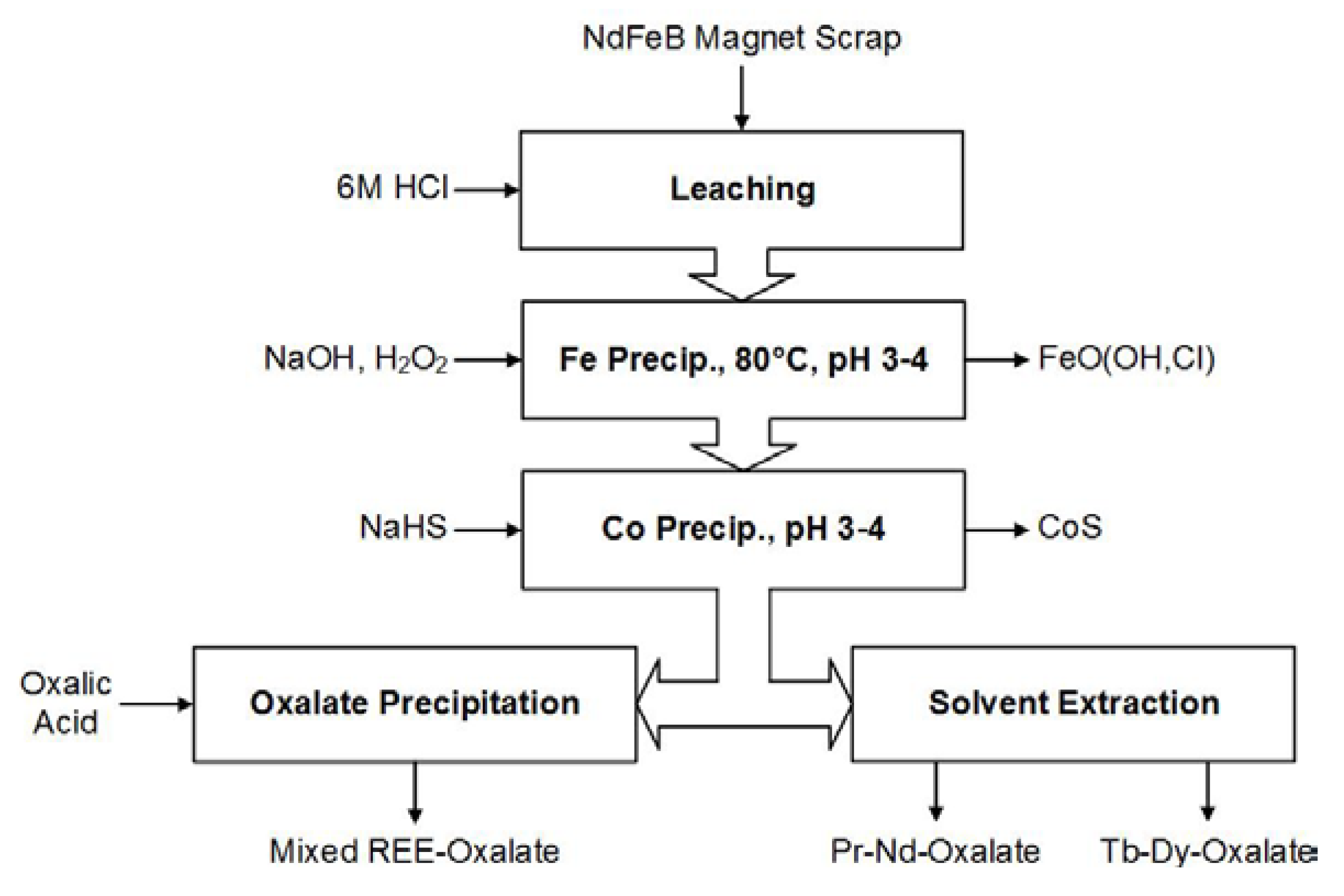
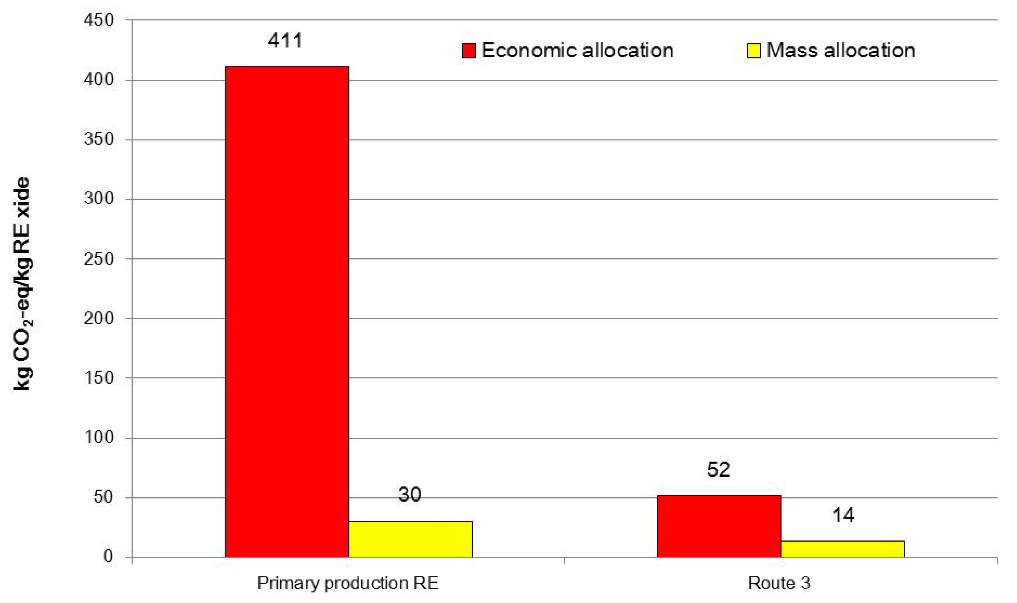
| Allocation approach | Nd | Dy |
|---|---|---|
| (kg CO2-eq./kg REE) | ||
| Economic allocation ** | 131 | 1159 |
| Mass allocation | 35 | 35 |

4.3. Power Electronics
5. Discussion and Conclusions
Acknowledgments
Author Contributions
Conflicts of Interest
References
- Khajepour, A.; Fallah, M.S.; Goodarzi, A. Electric and Hybrid Vehicles. Technologies, Modeling and Control: A Mechatronic Approach; Wiley: Chichester, UK, 2014. [Google Scholar]
- Pistoia, G. Electric and Hybrid Vehicles. Power Sources, Models, Sustainability, Infrastructure and the Market, 1st ed.; Elsevier: Amsterdam, the Netherlands, 2010. [Google Scholar]
- Warner, J. Lithium-Ion Battery Packs for EVs. In Lithium-Ion Batteries; Elsevier: Amsterdam, the Netherlands, 2014; pp. 127–150. [Google Scholar]
- Vuorilehto, K. Materialien und Funktion. In Handbuch Lithium-Ionen-Batterien; Korthauer, R., Ed.; Springer Berlin Heidelberg: Berlin, Germany, 2013; pp. 21–29. [Google Scholar]
- Treffer, F. Entwicklung Eines Realisierbaren Recyclingkonzeptes für die Hochleistungsbatterien Zukünftiger Elektrofahrzeuge: Lithium-Ionen Batterierecycling Initiative—LiBRi. Final Research Report. 2011. Available online: http://edok01.tib.uni-hannover.de/edoks/e01fb12/727409611.pdf. (accessed on 16 September 2015).
- Bast, U. Recycling von Komponenten und Strategischen Metallen aus Elektrischen Fahrantrieben: MORE (Motor Recycling). Final Research Report. 2014. Available online: http://edok01.tib.uni-hannover.de/edoks/e01fb15/826920594.pdf (accessed on 16 September 2015).
- European Commission. Report on Critical Raw Materials for the EU. 2014. Available online: http://ec.europa.eu/DocsRoom/documents/10010/attachments/1/translations/en/renditions/native (accessed on 16 September 2015).
- Angerer, G.; Marscheider-Weidemann, F.; Wendl, M.; Wietschel, M. Lithium für Zukunftstechnologien: Nachfrage und Angebot unter besonderer Berücksichtigung der Elektromobilität; Frauenhofer ISI: Karlsruhe, Germany, 2009; Available online: http://www.isi.fraunhofer.de/isi-wAssets/docs/n/de/publikationen/Lithium_fuer_Zukunftstechnologien.pdf (accessed on 16 September 2015).
- Öko-Institut e.V.; Institut für sozial-ökologische Forschung. OPTUM: Optimierung der Umweltentlastungspotenziale von Elektrofahrzeugen: Integrierte Betrachtung von Fahrzeugnutzung und Energiewirtschaft; Final Report: Berlin, Germany, 2011; Available online: http://www.oeko.de/oekodoc/1342/2011–004-de.pdf (accessed on 16 September 2015).
- Kühn, A.; Novinsky, P.; Schade, W. GLOMO—Global Mobility Model. Available online: http://publica.fraunhofer.de/documents/N-307006.html (accessed on 16 September 2015).
- Natkunarajhah, N.; Scharf, P. The variety of lithium-ion battery designs in xEV and their impact on the disassembly process. In Proceedings of the Advanced Automotive & Stationary Battery Conference, Mainz, Germany, 26–29 January 2015.
- Hanisch, C.; Diekmann, J.; Stieger, A.; Haselrieder, W.; Kwade, A. Recycling of Lithium-Ion Batteries. In Handbook of Clean Energy Systems; Yan, J., Ed.; John Wiley & Sons, Ltd.: Chichester, UK, 2015; pp. 2865–2888. [Google Scholar]
- Köhler, U. Aufbau von Lithium-Ionen-Batteriesystemen. In Handbuch Lithium-Ionen-Batterien; Korthauer, R., Ed.; Springer Berlin Heidelberg: Berlin, Germany, 2013; pp. 95–106. [Google Scholar]
- Huang, Z.; Du, G. Nickel-based batteries for medium- and large-scale energy storage. In Advances in Batteries for Medium and Large-Scale Energy Storage; Elsevier: Amsterdam, the Netherlands, 2015; pp. 73–90. [Google Scholar]
- Graf, C. Kathodenmaterialien für Lithium-Ionen-Batterien. In Handbuch Lithium-Ionen-Batterien; Korthauer, Ed.; Springer Berlin Heidelberg: Berlin, Germany, 2013; pp. 31–44. [Google Scholar]
- Wurm, C.; Öttinger, O.; Wittkämper, S.; Zauter, R.; Vuorilehto, K. Anodenmaterialien für Lithium-Ionen-Batterien. In Handbuch Lithium-Ionen-Batterien; Korthauer, R., Ed.; Springer Berlin Heidelberg: Berlin, Germany, 2013; pp. 45–60. [Google Scholar]
- Hartnig, C.; Schmidt, M. Elektrolyte und Leitsalze. In Handbuch Lithium-Ionen-Batterien; Korthauer, R., Ed.; Springer Berlin Heidelberg: Berlin, Germany, 2013; pp. 61–77. [Google Scholar]
- Weber, C.J.; Roth, M. Separatoren. In Handbuch Lithium-Ionen-Batterien; Korthauer, R., Ed.; Springer Berlin Heidelberg: Berlin, Germany, 2013; pp. 79–93. [Google Scholar]
- Buchert, M.; Jenseits, W.; Merz, C.; Schüler, D. Verbundprojekt: Entwicklung Eines Realisierbaren Recyclingkonzepts für die Hochleistungsbatterien zukünftiger Elektrofahrzeuge—LiBRi: Teilprojekt: LCA der Recyclingverfahren. Final Report. Darmstadt, Germany, 2011. Available online: http://www.erneuerbar-mobil.de/de/projekte/foerderprojekte-aus-dem-konjunkturpaket-ii-2009-2011/batterierecycling/abschlussberichte-recycling/lca-analyse-libri.pdf (accessed on 16 September 2015).
- Hofman, T. Hybrid drive train technologies for vehicles. In Alternative Fuels and Advanced Vehicle Technologies for Improved Environmental Performance; Elsevier: Amsterdam, the Netherlands, 2014; pp. 567–581. [Google Scholar]
- De Santiago, J.; Bernhoff, H.; Ekergård, B.; Eriksson, S.; Ferhatovic, S.; Waters, R.; Leijon, M. Electrical Motor Drivelines in Commercial All-Electric Vehicles: A Review. IEEE Trans. Veh. Technol. 2012, 61, 475–484. [Google Scholar] [CrossRef]
- Chau, K.T. Pure electric vehicles. In Alternative Fuels and Advanced Vehicle Technologies for Improved Environmental Performance; Elsevier: Cambridge, MA, USA, 2014; pp. 655–684. [Google Scholar]
- Matthé, R.; Eberle, U. The Voltec System—Energy Storage and Electric Propulsion. In Lithium-Ion Batteries; Elsevier: Amsterdam, the Netherlands, 2014; pp. 151–176. [Google Scholar]
- Widmer, J.D.; Martin, R.; Kimiabeigi, M. Electric vehicle traction motors without rare earth magnets. Sustain. Mater. Technol. 2015, 3, 7–13. [Google Scholar] [CrossRef]
- Orecchini, F.; Santiangeli, A.; Dell’Era, A. EVs and HEVs Using Lithium-Ion Batteries. In Lithium-Ion. Batteries; Elsevier: Amsterdam, the Netherlands, 2014; pp. 205–248. [Google Scholar]
- Hutchinson, T.; Burgess, S.; Herrmann, G. Current hybrid-electric powertrain architectures: Applying empirical design data to life cycle assessment and whole-life cost analysis. Appl. Energy 2014, 119, 314–329. [Google Scholar] [CrossRef]
- Schieffer, T.; Jeffers, M.A.; Hawkins, S.; Heisel, A.; Leahy, C.; Rapa, E.; Twarog, C. Spark EV Propulsion System Integration. In Proceedings of the SAE 2014 World Congress & Exhibition, Warrendale, PA, USA, 8–10 April 2014.
- Inside EVs. 2014 Monthly Sales Chart for the Major Plug-in Automakers. 2015. Available online: http://insideevs.com/monthly-plug-in-sales-scorecard/ (accessed on 16 September 2015).
- Kara, H.; Chapman, A.; Crichton, T.; Willis, P.; Morley, N. Lanthanide Resources and Alternatives. A report for the Department for Transport and the Department for Business, Innovation and Skills. 2010. Available online: http://www.oakdenehollins.co.uk/media/205/lanthanide_resources_and_alternatives_may_2010.pdf (accessed on 16 September 2015).
- Katter, M. Entwicklungstrends bei Pulvermetallurgisch Hergestellten Seltenerd-Dauermagneten. In Proceedings of the Workshop Magnetwerkstoffe—Vom Design bis zum Recycling, Bremen, Germany, 19–20 May 2015.
- Federal Institute for Geosciences and Natural Resources. Preismonitor. May 2015. Available online: http://www.deutsche-rohstoffagentur.de/EN/Themen/Min_rohstoffe/Produkte/Preisliste/cpl_15_04.pdf;jsessionid=9A61EBD61E6233799578A87A817D765F.1_cid292?__blob=publicationFile&v=3 (accessed on 16 September 2015).
- Liu, R.; Sun, X.; Gong, J.; Guo, S. Comparison of different arrangement of magnets for the purpose of reducing magnet usage in designing an IPM motor for Electric Vehicles. In Proceedings of the IEEE Transportation Electrification Conference and Expo, Asia-Pacific (ITEC Asia-Pacific), Beijing, China, 31 August–3 September 2014; pp. 1–5.
- Willard, M. Stronger, Lighter, and More Energy Efficient: Challenges of Magnetic Material Development for Vehicle Electricification. In Frontiers of Engineering; Reports on Leading-Edge Engineering from the 2012 Symposium, National Academy of Engineering; The National Academies Press: Washington, DC, USA, 2013. [Google Scholar]
- Morimoto, S.; Ooi, S.; Inoue, Y.; Sanada, M. Experimental Evaluation of a Rare-Earth-Free PMASynRM with Ferrite Magnets for Automotive Applications. IEEE Trans. Ind. Electron. 2014, 61, 5749–5756. [Google Scholar] [CrossRef]
- Matsuhashi, D.; Matsuo, K.; Okitsu, T.; Ashikaga, T.; Mizuno, T. Comparison study of various motors for EVs and the potentiality of a ferrite magnet motor. In Proceedings of the International Power Electronics Conference (IPEC-Hiroshima 2014 ECCE-ASIA), Hiroshima, Japan, 18–21 May 2014; pp. 1886–1891.
- Stancu, C.; Ward, T.; Rahman, K.; Dawsey, R.; Savagian, P. Separately excited synchronous motor with rotary transformer for hybrid vehicle application. In Proceedings of the IEEE Energy Conversion Congress and Exposition (ECCE), Pittsburgh, PA, USA, 14–18 September 2014; pp. 5844–5851.
- Ruff, B.; Li, W.; Venkatasubramanian, R.; Mast, D.; Sowani, A.; Schulz, M.; Harned, T.J. Development of Lightweight Sustainable Electric Motors. In Nanotube Superfiber Materials; Elsevier: Oxford, UK, 2014; pp. 595–626. [Google Scholar]
- Jain, M.; Williamson, S.S. Suitability analysis of in-wheel motor direct drives for electric and hybrid electric vehicles. In Proceedings of the Electrical Power & Energy Conference (EPEC), Montreal, QC, Canada, 22–23 October 2009; pp. 1–5.
- Murata, S. Innovation by in-wheel-motor drive unit. Veh. Syst. Dyn. 2012, 50, 807–830. [Google Scholar] [CrossRef]
- Muttana, S.B.; Dey, R.K.; Sardar, A. Trends in Lightweighting of BEVs: A Review of Strategies. Auto. Tech. Rev. 2014, 3, 18–23. [Google Scholar] [CrossRef]
- Spath, D.; Rothfuss, F.; Hermann, F.; Voigt, S.; Brand, M.; Fischer, S.; Ernst, T.; Loleit, M. Structure Study BWe Mobile 2011: Baden-Württemberg on the Way to Electromobility. 2011. Available online: http://www.e-mobilbw.de/files/e-mobil/content/DE/Service/Publikationen/e-papers/e_mobil_structure_study_en/files/mobile/index.html#1 (accessed on 16 September 2015).
- Schüler, D. Division Infrastructure & Enterprises, Oeko-Institut e. V.—Institute for Applied Ecology, Darmstadt, Germany Personal communication. , 2015.
- Grasshoff, T. Einen Schritt voraus: Aufbau-und Verbindungstechnik optimiert Leistungselektronik. Elektron. J. 2011, 2, 12–14. [Google Scholar]
- Eckardt, S. Roundtable im Hochhaus: Galliumnitrid und Siliziumkarbid im Vergleich. Elektron. J. 2011, 2, 16–21. [Google Scholar]
- Shenai, K.; Dudley, M.; Davis, R.F. Current Status and Emerging Trends in Wide Bandgap (WBG) Semiconductor Power Switching Devices. ECS J. Solid State Sci. Technol. 2013, 2, 3055–3063. [Google Scholar] [CrossRef]
- Fraunhofer Institute for Integrated Systems and Device Technology. Günstigere Elektrofahrzeuge Durch Motorintegrierte Leistungselektronik; Start für Projekt EMiLE: Erlangen, Germany, 2013. [Google Scholar]
- Elsner, H. Zinn: Angebot und Nachfrage bis 2020. DERA Rohstoffinformationen, 20; Bundesanstalt für Geowissenschaften und Rohstoffe, Ed.; Berlin, 2014. Available online: http://www.bgr.bund.de/DE/Gemeinsames/Produkte/Downloads/DERA_Rohstoffinformationen/rohstoffinformationen-20.pdf?__blob=publicationFile&v=7 (accessed on 16 September 2015).
- US Geological Survey. Mineral Commodity Summaries 2015. US Geological Survey, 2015. Available online: http://0-dx-doi-org.brum.beds.ac.uk/10.3133/70140094 (accessed on 16 September 2015). [Google Scholar]
- British Geological Survey. Cobalt. Comodity Profile. 2009. Available online: http://www.bgs.ac.uk/downloads/start.cfm?id=1400 (accessed on 16 September 2015).
- Minor Metals Trade Association. Cobalt Market Overview. Available online: http://www.mmta.co.uk/cobalt-market-overview (accessed on 7 April 2015).
- Eurostat. Energy, Transport and Enivonment Indicators; Publications Office of the European Union: Luxenbourg, Luxembourg, 2014. [Google Scholar]
- Edwards, C.; Coates, G.; Leaney, P.G.; Rahimifard, S. Implications of the End-of-Life Vehicles Directive on the vehicle recovery sector. J. Eng. Manuf. 2006, 220, 1211–1216. [Google Scholar] [CrossRef] [Green Version]
- Sakai, S.-I.; Yoshida, H.; Hiratsuka, J.; Vandecasteele, C.; Kohlmeyer, R.; Rotter, V.S.; Passarini, F.; Santini, A.; Peeler, M.; Li, J.; et al. An international comparative study of end-of-life vehicle (ELV) recycling systems. J. Mater. Cycles Waste Manag. 2014, 16, 1–20. [Google Scholar] [CrossRef]
- Vermeulen, I.; van Caneghem, J.; Block, C.; Baeyens, J.; Vandecasteele, C. Automotive shredder residue (ASR): Reviewing its production from end-of-life vehicles (ELVs) and its recycling, energy or chemicals’ valorisation. J. Hazard. Mater. 2011, 190, 8–27. [Google Scholar] [CrossRef] [PubMed]
- Kohlmeyer, R.; Groke, M.; Sander, K.; Bergamos, M. Perspektiven der zunehmenden Fahrzeugelektronik für das Altfahrzeugrecycling. In Recycling und Rohstoffe; Goldmann, D., Thomé-Kozmiensky, K.J., Eds.; TK-Verlag Karl Thomé-Kozmiensky: Neuruppin, Germany, 2015; pp. 183–205. [Google Scholar]
- Holzhauer, R. Altauto-Demontage: Bisherige Entwicklungen und Realität. In Recycling und Rohstoffe; Thomé-Kozmiensky, K.J., Goldmann, D., Eds.; TK-Verlag Karl Thomé-Kozmiensky: Neuruppin, Germany, 2015; pp. 151–171. [Google Scholar]
- Ferrão, P.; Nazareth, P.; Amaral, J. Strategies for Meeting EU End-of-Life Vehicle Reuse/Recovery Targets. J. Ind. Ecol. 2006, 10, 77–93. [Google Scholar] [CrossRef]
- Martens, H. Recyclingtechnik; Spektrum Akademischer Verlag: Heidelberg, Germany, 2011. [Google Scholar]
- Ciacci, L.; Morselli, L.; Passarini, F.; Santini, A.; Vassura, I. A comparison among different automotive shredder residue treatment processes. Int. J. Life Cycle Assess. 2010, 15, 896–906. [Google Scholar] [CrossRef]
- Widmer, R.; Du, X.; Haag, O.; Restrepo, E.; Wäger, P.A. Scarce Metals in Conventional Passenger Vehicles and End-of-Life Vehicle Shredder Output. Environ. Sci. Technol. 2015, 2. [Google Scholar] [CrossRef] [PubMed]
- Passarini, F.; Ciacci, L.; Santini, A.; Vassura, I.; Morselli, L. Auto shredder residue LCA: Implications of ASR composition evolution. J. Clean. Prod. 2012, 23, 28–36. [Google Scholar] [CrossRef]
- Ahmed, N.; Wenzel, H.; Hansen, J.B. Characterization of Shredder Residues generated and deposited in Denmark. Waste Manag. 2014, 34, 1279–1288. [Google Scholar] [CrossRef] [PubMed]
- Lieberwirth, H.; Krampitz, T. Entwicklungstendenzen für den Einsatz von Leichtbauwerkstoffen im Fahrzeugbau und Auswirkungen auf das Recycling. In Recycling und Rohstoffe; Thomé-Kozmiensky, K.J., Goldmann, D., Eds.; TK-Verlag Karl Thomé-Kozmiensky: Neuruppin, Germany, 2015; pp. 208–218. [Google Scholar]
- Pehlken, A.; Kalverkamp, M. Kaskadennutzung im Automobil: Realität oder Zukunftsmusik? In Recycling und Rohstoffe; Thomé-Kozmiensky, K.J., Goldmann, D., Eds.; TK-Verlag Karl Thomé-Kozmiensky: Neuruppin, Germany, 2015; pp. 174–181. [Google Scholar]
- Blume, T.; Walther, M. The End-of-life Vehicle Ordinance in the German Automotive Industry—Corporate Sense Making Illustrated. J. Clean. Prod. 2013, 56, 29–38. [Google Scholar] [CrossRef]
- Gradin, K.T.; Luttropp, C.; Björklund, A. Investigating improved vehicle dismantling and fragmentation technology. J. Clean. Prod. 2013, 54, 23–29. [Google Scholar] [CrossRef]
- Kwade, A.; Bärwald, G. Recycling von Lithium-Ionen-Batterien; Final Report; Braunschweig, Germany, 2012; Available online: http://www.erneuerbar-mobil.de/de/projekte/foerderprojekte-aus-dem-konjunkturpaket-ii-2009–2011/batterierecycling/abschlussberichte-recycling/abschlussbericht-lithorec.pdf (accessed on 16 September 2015).
- Hörnig, G. Recycling von NdFeB-Magneten aus elektrischen Antrieben—Das Projekt MORE. In Recycling und Rohstoffe; Thomé-Kozmiensky, K.J., Goldmann, D., Eds.; TK-Verlag Karl Thomé-Kozmiensky: Neuruppin, Germany, 2015. [Google Scholar]
- Tytgat, J.; Treffer, F. Recycling of Li-ion and NiMH batteries from electric vehicles: Technology and impact on life cycle. In Proceeding of the Belgian Platform on Electrical Vehicles, Brussels, Belgium, 31 March 2011.
- Friedrich, B. Rückgewinnung der Wertstoffe aus zukünftigen Li-Ion-basierten Automobil-Batterien: Lithium-Ionen-Batterie (LIB2015). Final Report. 2012. Available online: http://edok01.tib.uni-hannover.de/edoks/e01fb13/769010806.pdf (accessed on 16 September 2015).
- Vezzini, A. Manufacturers, Materials and Recycling Technologies. In Lithium-Ion Batteries; Elsevier: Oxford, UK, 2014; pp. 529–551. [Google Scholar]
- Tytgat, J. Li-Ion and NiMH Battery Recycling at Umicore: Strategic Choices. ERTRAC Expert Workshop: Brussels, 19 June 2009. Available online: http://www.smart-systems-integration.org/public/electric-vehicle/battery-workshop-documents/presentations/Jan%20Tytgat%20Umicore.pdf/at_download/file (accessed on 9 July 2015).
- Elwert, T.; Goldmann, D.; Schirmer, T.; Strauß, K. Recycling of lithium ion traction batteries: The LiBRi project. In Proceedings of the European Mineral Resources Conference, Leoben, Austria, 19–21 September 2012; pp. 575–603.
- Schmid, D.; Zur-Lage, L. Perspektiven für das Recycling von Altfahrzeugen—Moderne Fahrzeuge und angepasste Recyclingverfahren. In Recycling und Rohstoffe, Band 7; Thomé- Kozmiensky, K.J., Goldmann, D., Eds.; TK-Vlg: Neuruppin, Germany, 2014. [Google Scholar]
- Hanisch, C. Recycling of Lithium-Ion. Batteries; Lion-Engineering. 14 June 2014. Available online: http://www.lion-eng.de/images/pdf/Recycling-of-Lithium-Ion-Batteries-LionEngineering.pdf%20 (accessed on 16 September 2015).
- Hoyer, C. Strategische Planung des Recyclings von Lithium-Ionen-Batterien aus Elektrofahrzeugen in Deutschland; Springer Fachmedien Wiesbaden: Wiesbaden, Germany, 2015. [Google Scholar]
- Hanisch, C.; Haselrieder, W.; Kwade, A. Verfahren zum Wiedergewinnen von Aktivmaterial aus Einer Galvanischen Zelle und Aktivmaterial-Separationsanlage, Insbesondere Aktivmetall-Separationsanlage. Available online: https://data.epo.org/publication-server/rest/v1.0/publication-dates/20150930/patents/EP2742559NWB1/document.pdf (accessed on 16 September 2015).
- Grützke, M.; Mönnighoff, X.; Horsthemke, F.; Kraft, V.; Winter, M.; Nowak, S. Extraction of lithium-ion battery electrolytes with liquid and supercritical carbon dioxide and additional solvents. RSC Adv. 2015, 5, 43209–43217. [Google Scholar] [CrossRef]
- Jäckel, H.-G.; Wuschke, L.; Peuker, U.A. Probleme der Aufbereitung metallhaltiger Werkstoffverbunde aus lithiumhaltigen Geräten und Batterien. Chem. Ing. Tech. 2014, 86, 806–813. [Google Scholar] [CrossRef]
- Buchert, M.; Jenseits, W.; Merz, C.; Schüler, D. Ökobilanz zum, Recycling von Lithium-Ionen-Batterien (LithoRec); Final Report: Darmstadt, 2011; Available online: http://www.erneuerbar-mobil.de/de/projekte/foerderprojekte-aus-dem-konjunkturpaket-ii-2009–2011/batterierecycling/abschlussberichte-recycling/lca-analyse-lithorec.pdf (accessed on 16 September 2015).
- Walachowicz, F.; March, A.; Fiedler, S.; Buchert, M.; Sutter, J.; Merz, C. Recycling von Elektromotoren—MORE: Ökobilanz der Recyclingverfahren; Final Report: Darmstadt, Germany, 2014; Available online: http://de.slideshare.net/AndrewMarch/morelcaendberichtfinal17okt2014 (accessed on 16 September 2015).
- Klier, T.; Risch, F.; Franke, J. Disassembly strategies for recovering valuable magnet material of electric drives. In Proceedings of the 2013 3rd International Electric Drives Production Conference (EDPC), Nürnberg, Germany, 29–30 October 2013; pp. 1–3.
- Klier, T.; Risch, F.; Franke, J. Disassembly, recycling, and reuse of magnet material of electric drives. In Proceedings of the 2013 IEEE International Symposium on Assembly and Manufacturing (ISAM), Xi’an, China, 30 July 30–2 August 2013; pp. 88–90.
- MORE Consortium. “MORE”—A Project on Recycling of Components and Strategic Metals of Electric Drive Motors; Final Presentation of the Research Project; MORE Consortium: München, Germany, 2015. [Google Scholar]
- Graedel, T.E.; Allwood, J.; Birat, J.-P.; Buchert, M.; Hagelüken, C.; Reck, B.K.; Sibley, S.F.; Sonnemann, G. Recycling Rates of Metals; United Nations Environment Programme: Nairobi, Kenya, 2011. [Google Scholar]
- Binnemans, K.; Jones, P.T.; Blanpain, B.; van Gerven, T.; Yang, Y.; Walton, A.; Buchert, M. Recycling of rare earths: A critical review. J. Clean. Prod. 2013, 51, 1–22. [Google Scholar] [CrossRef]
- Elwert, T.; Goldmann, D.; Schmidt, F.; Stollmaier, R. Hydrometallurgical recycling of sintered NdFeB magnets. World Metall. 2013, 66, 209–219. [Google Scholar]
- Elwert, T.; Goldmann, D.; Römer, F. Separation of lanthanides from NdFeB magnets on a mixer-settler plant with PC-88A. World Metall. 2014, 67, 287–296. [Google Scholar]
- Elwert, T. Entwicklung eines hydrometallurgischen Recyclingverfahrens für NdFeB-Magnete. Papierflieger: Clausthal-Zellerfeld, Germany, 2015. [Google Scholar]
- Van Schaik, A.; Reuter, M.A. Material-Centric (Aluminum and Copper) and Product-Centric (Cars, WEEE, TV, Lamps, Batteries, Catalysts) Recycling and DfR Rules. In Handbook of Recycling: State-of-the-Art for Practitioners, Analysts, and Scientists; Worrell, E., Reuter, M., Eds.; Elsevier: Waltham, UK, 2014; pp. 307–378. [Google Scholar]
© 2015 by the authors; licensee MDPI, Basel, Switzerland. This article is an open access article distributed under the terms and conditions of the Creative Commons Attribution license (http://creativecommons.org/licenses/by/4.0/).
Share and Cite
Elwert, T.; Goldmann, D.; Römer, F.; Buchert, M.; Merz, C.; Schueler, D.; Sutter, J. Current Developments and Challenges in the Recycling of Key Components of (Hybrid) Electric Vehicles. Recycling 2016, 1, 25-60. https://0-doi-org.brum.beds.ac.uk/10.3390/recycling1010025
Elwert T, Goldmann D, Römer F, Buchert M, Merz C, Schueler D, Sutter J. Current Developments and Challenges in the Recycling of Key Components of (Hybrid) Electric Vehicles. Recycling. 2016; 1(1):25-60. https://0-doi-org.brum.beds.ac.uk/10.3390/recycling1010025
Chicago/Turabian StyleElwert, Tobias, Daniel Goldmann, Felix Römer, Matthias Buchert, Cornelia Merz, Doris Schueler, and Juergen Sutter. 2016. "Current Developments and Challenges in the Recycling of Key Components of (Hybrid) Electric Vehicles" Recycling 1, no. 1: 25-60. https://0-doi-org.brum.beds.ac.uk/10.3390/recycling1010025