Boron-Based Neutron Scintillator Screens for Neutron Imaging
by
William Chuirazzi
1,*, 
Aaron Craft
1,
Burkhard Schillinger
2,
Steven Cool
3 and
Alessandro Tengattini
4,5 1
Advanced Post-Irradiation Examination Department, Idaho National Laboratory, Idaho Falls, ID 83401, USA
2
Heinz Maier-Leibnitz Zentrum (FRM II) and Faculty for Physics E21, Heinz Maier-Leibnitz Zentrum (FRM II), Technische Universität München, 85748 Garching, Germany
3
DMI/Reading Imaging, Reading, MA 01867, USA
4
Le Centre National de la Recherche Scientifique (CNRS), Université Grenoble Alpes, Grenoble INP, 3SR, 38000 Grenoble, France
5
Institut Laue-Langevin (ILL), 71 Avenue des Martyrs, 38000 Grenoble, France
*
Author to whom correspondence should be addressed.
J. Imaging 2020, 6(11), 124; https://0-doi-org.brum.beds.ac.uk/10.3390/jimaging6110124
Submission received: 27 October 2020
/
Revised: 12 November 2020
/
Accepted: 16 November 2020
/
Published: 19 November 2020
(This article belongs to the Special Issue Neutron Imaging)
Abstract
:In digital neutron imaging, the neutron scintillator screen is a limiting factor of spatial resolution and neutron capture efficiency and must be improved to enhance the capabilities of digital neutron imaging systems. Commonly used neutron scintillators are based on 6LiF and gadolinium oxysulfide neutron converters. This work explores boron-based neutron scintillators because 10B has a neutron absorption cross-section four times greater than 6Li, less energetic daughter products than Gd and 6Li, and lower γ-ray sensitivity than Gd. These factors all suggest that, although borated neutron scintillators may not produce as much light as 6Li-based screens, they may offer improved neutron statistics and spatial resolution. This work conducts a parametric study to determine the effects of various boron neutron converters, scintillator and converter particle sizes, converter-to-scintillator mix ratio, substrate materials, and sensor construction on image quality. The best performing boron-based scintillator screens demonstrated an improvement in neutron detection efficiency when compared with a common 6LiF/ZnS scintillator, with a 125% increase in thermal neutron detection efficiency and 67% increase in epithermal neutron detection efficiency. The spatial resolution of high-resolution borated scintillators was measured, and the neutron tomography of a test object was successfully performed using some of the boron-based screens that exhibited the highest spatial resolution. For some applications, boron-based scintillators can be utilized to increase the performance of a digital neutron imaging system by reducing acquisition times and improving neutron statistics.
1. Introduction
1.1. Background
Neutron imaging is a nondestructive examination technique that measures neutron transmission to examine a sample’s internal structure. This technique has been used in a variety of studies, including those of nuclear fuels and materials [1,2,3,4,5,6], cultural heritage objects [7,8,9], fuel cells [10,11,12,13,14], turbine blades [15,16,17], and many others. Digital neutron imaging techniques are now an essential capability for any state-of-the-art neutron imaging facility [18]. The most common digital neutron imaging system consists of a digital camera optically coupled to a neutron-sensitive scintillator screen.
A critical component of digital neutron imaging systems is the neutron scintillator, because the scintillator dictates the neutron capture efficiency and is a limiting factor in spatial resolution. Common scintillator screens for thermal and cold neutron imaging utilize either a 6Li(n,α)3H reaction due to its large neutron absorption cross-section and relatively large reaction energy, or a Gd(n,γ + ICe−) reaction because of gadolinium’s high neutron absorption cross-section [19,20,21,22,23]. Although these scintillator screens are the state of the art in the digital neutron imaging community, the continual improvement of neutron scintillators are necessary to meet the ever-higher user demands for increased spatial resolution to examine smaller samples and increased detection efficiency to decrease measurement time.
Boron-based screens offer a promising alternative to existing 6Li- and Gd-based neutron scintillator screens for a number of reasons. First, the thermal neutron cross-section of 10B (3840 b) is approximately four times greater than that of 6Li (980 b), as shown in Figure 1, which should increase the neutron detection efficiency for a comparable 6Li-based screen. Second, the daughter products created by neutron absorption of 10B have less total energy (2.31 MeV or 2.79 MeV) than those of 6Li (4.78 MeV) and Gd (7.937 MeV or 8.536 MeV), and the lower energy from a 10B(n,α)7Li reaction is distributed on heavier daughter products compared to a 6Li(n,α)3H reaction. The lower energy and larger size of the daughter products reduces the range the daughter products will travel, a fundamental limiting factor of a screen’s spatial resolution, potentially enabling borated scintillator screens to exhibit higher spatial resolution compared to the screens created with 6Li or Gd. Additionally, 10B has a lower γ-ray sensitivity than gadolinium due to its lower atomic number. Scintillator screens with a boron converter can theoretically be made much thinner than current 6Li- and Gd-based screens, while exhibiting superior neutron detection efficiency to 6Li scintillator screens, improved γ-ray insensitivity over Gd scintillator screens, and improved spatial resolution. The combination of 10B’s improved neutron detection efficiency, spatial resolution, and γ-ray insensitivity could potentially provide a high-performance neutron scintillator.
Boron-based neutron scintillators for neutron imaging applications were conceived as early as the 1950s [24,25] and their superior neutron detection efficiency has been documented [26]. Glass scintillators [27,28], scintillators with a mixture of neutron absorbing materials [29,30], and plastic scintillators [31,32,33,34] have all utilized boron for neutron detection in different contexts. Despite their usefulness in other applications, previous studies have generally concluded that boron-based scintillator screens’ poor light output prevented them from becoming a viable scintillator for neutron imaging [35,36,37]. However, Nakamura et al.’s work [38] suggests smaller boron particles may increase light output performance. More recent efforts by other colleagues in the neutron imaging field have recently explored using 10B/CsI:Tl scintillator screens for neutron imaging [39].
The working hypothesis of this study is that the low probability of 10B’s daughter products to escape from the boron-containing particle and arrive as a scintillating particle is the likely cause of the low light output observed in previous investigations of boron-based neutron scintillator screens. This work aims to use smaller boron converter particles to enhance light output. The goal of this investigation is to benefit the broader neutron imaging community by exploring boron-based scintillator screens that may deliver improved neutron detection efficiency, light output, and potentially spatial resolution.
1.2. Theory of Boron-Based Scintillator Screens
The range of daughter products created when a neutron interacts with a neutron converter is one of the limiting factors of a scintillator screen’s spatial resolution. When a thermal neutron (0.025 eV) is absorbed by 10B, a 10B(n,α)7Li reaction occurs with a 94% branching ratio of producing a 7Li particle in an excited state (Equation (1)) and a 6% branching ratio of producing a 7Li in the ground state (Equation (2)), with an average reaction energy of 2.34 MeV. The daughter products of 10B have less energy than those created by thermal neutron interactions with 6Li (Equation (3)) and Gd (Equations (4) and (5)), causing them to deposit energy more locally to the interaction site and improve the theoretical spatial resolution limit. Additionally, 10B’s daughter products are more massive and deposit their energy over a shorter range than those of 6Li:
Natural gadolinium, which consists of seven stable isotopes, has a total thermal neutron cross-section of 48,800 barns. Two isotopes that have high thermal neutron capture cross-sections and a relatively high natural abundance are 155Gd (60,900 b, 14.8% abundance) and 157Gd (254,000 b, 15.7% abundance) [40]. As shown in Equations (4) and (5), gadolinium neutron absorption reactions produce prompt γ-rays and internal conversion electrons (ICe−), which also produce secondary characteristic X-rays and Auger electrons, including Coster–Kronig electrons. The γ-rays represent 99% of the Q-value energy [41], but the emitted electrons deposit their energy more locally than photons. Thus, the response of a gadolinium oxysulfide scintillator (e.g., GOS, Gd2O2S, informally known as Gadox) to thermal neutron capture is a combination of the effects of emitted photons and electrons. Different GOS scintillators (such as GOS:Tb, GOS:Pr, GOS:Eu) have different properties, such as peak light emission, photons/MeV, and decay time. These properties can be matched to the specific application requirements to maximize performance. Thermal neutron capture by 157Gd, for example, releases an average of 3.288 photons including prompt and secondary γ-rays and X-rays with energies ranging from 10s of eV up to several MeV and a mean energy of 2.394 MeV [42,43]. This same reaction also releases ICe− with energies ranging from 29 keV to 6.9 MeV, with the most intense discrete ICe− emissions of 29 and 71 keV [40,43,44]. The range of a 71 keV ICe− in gadolinium is approximately 20 µm [45]. Goorley and Nikjoo have compiled a more complete table of gadolinium spectral photon emissions [43].
Less energetic daughter products help improve spatial resolution because they have a shorter range in the surrounding material. The probability that the daughter products will escape the boron converter particles and reach the scintillator particles decreases with increasing converter particle size. When the converter particles themselves prevent daughter products from reaching the scintillator material and producing photons, the light output of the scintillator screen is reduced despite any apparent improvement in the detection efficiency from using 10B compared to 6Li. Thus, the converter particle size could explain the poor light output reported by previous studies on borated scintillator screens.
A Transmission of Ions in Matter (TRIM) simulation [46] calculated the ranges of the daughter products from the neutron absorption reactions of interest in the boron and lithium-based scintillator screens. TRIM does not account for isotopic information, so natural elemental abundances were used in the calculation. The range of internal conversion electrons in GOS scintillator screens was calculated using the Penetration and Energy Loss of Positrons and Electrons (PENELOPE) software (Version) [47]. Table 1 lists the daughter particles in the converter material, the converter material densities used for the simulation, and the resulting daughter product ranges, which are also displayed in Figure 2.
These simulations show 6Li daughter products traveling through LiF, as well as 10B daughter products traveling through a layer of B2O3, NaB5O8, or BN. The densities of NaB5O8 and Na10B5O8 were essential to analyzing the imaging results, but the density of anhydrous NaB5O8 was not available in the literature. The density of its hydrous form, Na2O·5(B2O3)·10(H2O) (i.e., NaB5H10O13), is known (with natB, 1.707 g/cm3 [48]; with 10B, 1.67 g/cm3). The density of Na10B5O8 was experimentally measured to be approximately 2.02 g/cm3, fixing the density of natural NaB5O8 at 2.06 g/cm3.
The triton from 6Li(n,α)3H has a range of 62.7 μm, which can easily escape a ~10 µm diameter converter particle to deposit most of its 2.78 MeV energy into the surrounding scintillator material. However, the 10B daughters deposit their energy almost an order of magnitude closer to the event origin than the 3H from 6Li. Thus, the majority of daughter products from a 10B(n,α)7Li reaction in a 10 µm diameter particle would not escape the particle to interact with any surrounding material, demonstrating the need for smaller boron particles to maximize the probability of conversion from absorbed neutrons in the converter to photon production from surrounding scintillator material.
The neutrons transmitted through a sample carry attenuation information about the sample, which are converted to photons by the scintillator, and read by a digital camera and sampled into pixels to form an image. Thus, the neutron counting statistics dictate image quality as long as the camera detects enough light to represent the number of neutrons absorbed in the scintillator screen.
Scintillators with a higher detection efficiency can offer shorter acquisition times and improved image quality (e.g., signal-to-noise ratio, SNR). Scintillator screens containing one or more effective converter materials detect neutrons by attenuating them through absorption, so screens that absorb more neutrons demonstrate increased neutron detection efficiency. Neutron attenuation is described by the Beer–Lambert law, shown in Equation (6), where ϕ0 is the initial neutron flux and ϕ(t) is the neutron flux after attenuation through a material of thickness, t, and total attenuation macroscopic cross-section, ΣTotal. The total attenuation cross-section (ΣTotal) is the sum of the scattering and absorption cross-sections (Σs and Σa, respectively). For the strongly absorbing materials considered here, Σa >> Σs, meaning the attenuation is driven by absorption and scattering effects are negligible, and ΣTotal ≈ Σa. Thus, a screen’s detection efficiency is the neutron attenuation fraction, (t)/ϕ0:
Calculated neutron detection efficiencies of various scintillator materials are listed in Table 2 and displayed in Figure 3. The attenuation curves for both thermal and cold neutrons show that gadolinium-based scintillators have the highest neutron detection efficiency. However, they have a large daughter product energy and are also sensitive to γ-rays. 10B-based scintillators have a significantly higher attenuation than 6Li scintillators, so a thinner borated scintillator screen can maintain the same detection efficiency as a thicker 6Li screen, further improving resolution by minimizing the potential for photon diffusion within the screen. This suggests that 10B-based screens should exhibit higher detection efficiency than 6Li-based screens, lower γ-ray sensitivity than gadolinium-based screens, and improved spatial resolution compared to both gadolinium-based and 6Li-based screens.
2. Materials and Methods
This study was divided into two phases, beginning with the initial scoping measurements of a narrow set of screen variations that informed the creation of a broader variety of screens for more detailed measurements. The following sections describe the scintillator screens created as part of this work along with the methods employed to characterize their performance.
2.1. Scintillator Screens
The purpose of this study was to conduct a combinatorial study of boron-based neutron scintillators to determine if (1) borated scintillator screens could offer improved neutron imaging capabilities compared to current widely-used screens and (2) which parameters produced the best performing screens.
2.1.1. Scintillator Screen Compositions
A total of 25 different boron-based scintillator screens were evaluated as part of the initial scoping studies, which are listed in Table 3. The results of this experiment allowed for a down-selection of scintillator screen parameters that informed the second phase of borated scintillator screen design and evaluation. All screens employed a ZnS:Cu scintillator and had an active area of 50 mm × 50 mm. Four screens layered the scintillator and converter materials separately, while the rest had a mixture of scintillator and converter material particles. These scoping studies included a larger variety of converter materials, and only the top few performing converters were pursued further in subsequent testing.
The second phase of this work examined 50 different boron-based scintillator screens, which are listed in Table 4. At least two of each screen variety were fabricated and tested to reduce any anomalous effects from fabrication. Some additional screens were fabricated with a single thickness for the acquisition of test images. This study utilized a total of 118 borated scintillator screens and six different 6LiF screens. Except for a few cases that used a 1.8 mm-thick first-surface mirror (FSM), all screens were mounted on 63 mm × 63 mm square aluminum substrates that were 1 mm thick.
Additional substrate materials were also tested. The active area of scintillator and converter material measured 50 mm × 50 mm and a ZnS:Cu scintillator was used for each screen. The ZnS:Cu scintillator was chosen because cameras used in this study have a higher quantum efficiency in the wavelengths emitted from ZnS:Cu than for ZnS:Ag. Screen performance was measured for sensors with a varying converter material (10B2O3, natBN, and Na10B5O8), scintillator median particle size (11.5 and 4.7 μm), converter-to-scintillator (boron atom to ZnS molecule) mix ratio (2:1, 1:1, and 1:2), and sensor substrate (FSM, matte black aluminum, polished aluminum, matte finish aluminum, broad-spectrum white polymer-coated aluminum, and broad-spectrum white polymer sheet adhered to aluminum). While the natBN and Na10B5O8 scintillator materials were obtained commercially, the 10B2O3 was fabricated specifically for this project using a precursor of 10B-enriched boric acid (H310BO3) and basic chemical and material processes.
Three separate types of scintillator screens were tested during this study. First, wedged screens consisting of mixed converter and scintillator material were tested to determine the impact of scintillator layer thickness on imaging performance. Second, screens with separate scintillator and converter layers as wedges of each layer, referred to as double wedge scintillator screens, were fabricated with the two wedges deposited in perpendicular directions so that a single double-wedged screen represents the full range of thicknesses for both the converter and scintillator materials. Third, screens with a thin, single-thickness scintillator layer were used to test some boron-based screens for neutron radiography.
2.1.2. Wedged Scintillator Screens
Screen thickness is one of the most impactful parameters that determines the performance of a scintillator screen. To determine screen performance as a function of thickness, one could fabricate multiple screens with a range of discrete thicknesses, measure the performance of each, and then interpolate between the data points. However, this is expensive and time-consuming.
This work simultaneously studies a continuous range of thicknesses using a wedged scintillator screen, where scintillator layer thickness varies continuously across the screen, as described in previous work [49]. The wedged screens were fabricated by first depositing a nominally 300 μm-thick scintillator layer onto the substrate. Then, a rigid blade was used to scrape the scintillator layer away until the target high and low thicknesses were reached with a monotonic gradient in between them. A jig was used to keep the blade at the proper angle. The resulting screens had a nominal maximum thickness of 300 μm that decreased to a thin layer a few microns thick. The as-fabricated scintillator thickness deposited on the substrate was measured with two different commercial coating thickness gauges that use eddy current probes. The measurements from both gauges were taken at the thicker portion of the screen and averaged together to produce a maximum as-fabricated thickness. A schematic of the wedged scintillator design emphasizing the wedge shape (exaggerated, not to scale) is shown in Figure 4. In total, 84 wedged screens were part of this study.
Figure 5 shows a photograph of a representative wedged screen taken with an oblique light applied to enhance the appearance of the surface texture in the picture. Multiple surface defects can be seen in these prototype screens, but these discontinuities are accounted for in the post-processing of experimental data [49]. The thicker section of the wedge is at the top of the image, with the thickness decreasing continuously toward the bottom of the screen.
2.1.3. Double-Wedged Scintillator Screens
Mixing the converter and scintillator particles is feasible for white converter particles because they do not absorb the light emitted from the scintillator like a dark-colored material would. This study tested the performance of dark boron-containing converters, including 10B4C and 10B metal, but separated them into a distinct layer from the scintillator in the form of a double-wedged scintillator screen. The converter layer was deposited directly onto an aluminum substrate and the thickness ranged from 100 µm to a few microns. The scintillator layer was deposited on top of the converter layer and varied from 300 μm to a few microns thick. The thickest parts of the two wedges were placed perpendicularly to each other, so each position of the scintillator screen represented a different combination of converter and scintillator layer thickness. This approach allowed a continuous range of thickness combinations to be assessed using a single screen. Nine separate double-wedged screens were included in this study. A double-wedged screen is displayed in Figure 6. The scintillator thickness varies from top (thicker) to bottom (thinner), while the converter is thickest on the right and decreases toward the left of the screen.
2.1.4. High-Resolution Scintillator Screens
Boron-based screens with uniformly thick scintillator coatings deposited as thin as possible were also explored in this study. The scintillator layers for these screens all had target maximum thicknesses of ≤ 20 μm. Light dispersion within the scintillator layer is a source of image unsharpness, so thin screens should exhibit higher spatial resolution. This part of the study explored the feasibility of achieving higher spatial resolution by exploiting boron’s increased neutron detection efficiency to offset the lower light output of a thinner screen. Figure 7 displays a photograph of a high-resolution screen under oblique lighting to emphasize screen texture. The missing portion of the coating was caused by the insufficient adhesion of the coating to the substrate during a delicate scraping operation to make the wedged thickness profile. However, this defect did not prohibit measurements because it is outside the central field of view (FOV) of the screen.
2.2. Neutron Source and Instrumentation
The measurements for this study were taken using the ANTARES cold neutron beam located at the FRM II reactor [50]. All radiographs were acquired with a neutron flux of 5.7 × 10⁷ n/cm2/s at the sample position and a length-to-diameter ratio (L/D) of 540, where L is the beamline length measured from the aperture to the image plane and D is the effective diameter of the aperture. A 1 mm-thick cadmium filter was placed in the beamline to filter thermal neutrons for the testing of the screens’ sensitivity to epithermal neutrons. ANTARES has two imaging systems, one with a larger FOV and another for high resolution applications. The large FOV system uses an Andor iKon-L camera (Andor iKon-L, Oxford Instruments, Belfast, UK). The high-resolution imaging system utilizes an Andor Neo camera (Andor Neo, Oxford Instruments, Belfast, UK). The peak light emission of the ZnS:Cu used in this study is ~530 nm, which matches well with the camera used to study light output, as the camera has > 90% quantum efficiency between ~480 and ~710 nm with a peak near 550 nm [51]. The large FOV system was used to simultaneously characterize multiple screens for detection efficiency and light output, and the high-resolution system was used for resolution testing and neutron tomography.
2.3. Testing Methodology
The goal of this study was to characterize the performance of a variety of boron-based scintillator screens to understand how different screen parameters affected the final imaging performance. Previous reports of low light output were a concern, so initial scoping studies focused on identifying borated screens that produced sufficient light output for neutron imaging applications and down-selecting the boron converter chemical form to the few most promising candidates for a subsequent set of screens and measurements. The second phase of testing measured the detection efficiency and light yield of the candidate scintillator screens for a wider variety of screen parameters. Spatial resolution was quantified by taking a radiograph of a 1 cm-wide, 75 µm-thick gadolinium strip and calculating the modulation transfer function (MTF) from the edge profile.
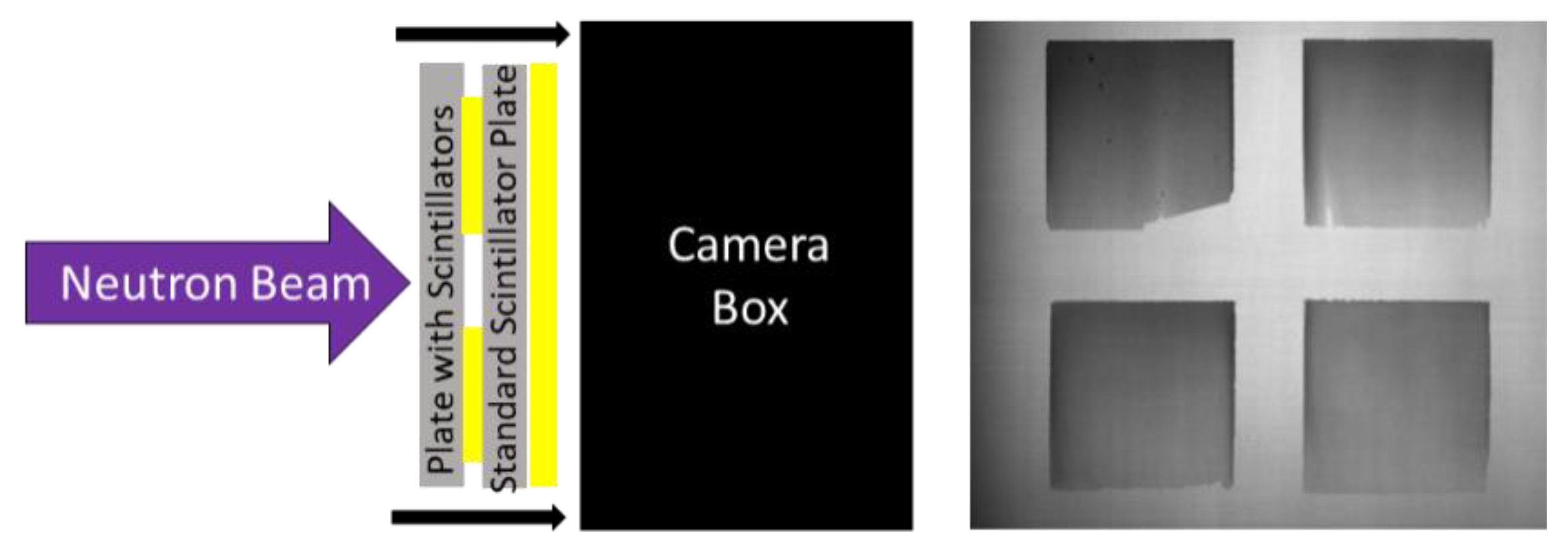
Light output and detection efficiency were measured using previously developed methodology [49]. The larger FOV imaging system was used for these measurements because four screens could be simultaneously measured in a single radiograph. First, radiographs were acquired with the borated screens optically coupled directly to the imaging system to measure the relative light output of each screen. For cold neutron radiographs, this consisted of a single six-second exposure. Epithermal testing was performed by acquiring five 20 s exposures and summing them together. A diagram of this measurement and a sample radiograph from it are displayed in Figure 8.
Once the radiograph measuring the light yield of the screens was captured, the borated screens were removed from the imaging system and a common 6LiF/ZnS:Cu screen was mounted to the imaging system. An open beam image was acquired for the post-process correction of subsequent radiographs. The borated screens were then placed on the source-side of the 6LiF/ZnS:Cu screen and a radiograph of the borated screens was acquired to measure the detection efficiency of each screen. Figure 9 shows a schematic of this setup, as well as a representative radiograph of this measurement. There was a gap of only 8 mm between the image plane and the borated screens, so the magnification effects were negligible. This procedure was performed for the double- and single-wedged screens with the cold neutron beam. Epithermal measurements using the same process with a cadmium-filtered beam were also conducted with the single wedge screens.
2.4. Data Processing
A median filter (3 × 3-pixel radius) was applied to all images to reduce noise in the radiographs used to measure relative light output and detection efficiency. All radiographs were open-beam and dark-field corrected. Acquisition times were six seconds for the images taken in the unfiltered cold beam. For the epithermal (i.e., cadmium-filtered) beam, a set of five 20-second images were taken for each measurement and summed together. Spatial resolution images were integrated over ten seconds. A python code was written to correlate data from both the light-yield and detection-efficiency measurements for each screen. Once correlated, relative light yield and detection efficiency as a function of scintillator layer thickness was calculated. A separate python script calculated the effective spatial resolution in terms of MTF. More details on the measurement procedure and data analysis methods can be found in Chuirazzi et al. [49].
3. Results
3.1. Results of Initial Scoping Studies
The light outputs of the first set of borated neutron scintillator screens was measured, which are shown in Figure 10. Scintillator screens with layered converter and scintillator material produced minimal light output. The performance of sensors with a converter and scintillator mixture varied based on the converter material and mix ratios. More converter means less scintillator, and vice versa. Too much converter means there is not enough scintillator to produce photons, and too much scintillator means there is not enough converter to absorb the neutrons. There will be an optimal mixture ratio. Thus, the light output does not necessarily change monotonically with the mix ratio.
The highest performing screens in these initial scoping measurements included 10B2O3, natBN, and Na10B5O8. The light output of the 10B2O3 screens was notably higher for screens on FSM than for a matte black aluminum substrate, indicating that further study of substrate variations may be warranted. Results of this testing informed the fabrication of additional boron-based scintillator screens. This second generation of screens focused on 10B2O3, natBN, and Na10B5O8 converter materials.
3.2. Additional Testing
Converter material, converter grain size, converter-to-scintillator mix ratio, and substrate material were all varied to investigate their impact on the scintillator screens’ performance. The results of the data taken in the cold neutron beam are reported first, followed by epithermal neutron results. Duplicate screens were fabricated with the same combination of screen parameters, and the results of duplicate screens were averaged to reduce the effects of any outliers. Relative light yield is normalized to the single brightest screen to facilitate a relative comparison between all screens.
3.2.1. Cold Neutron Results
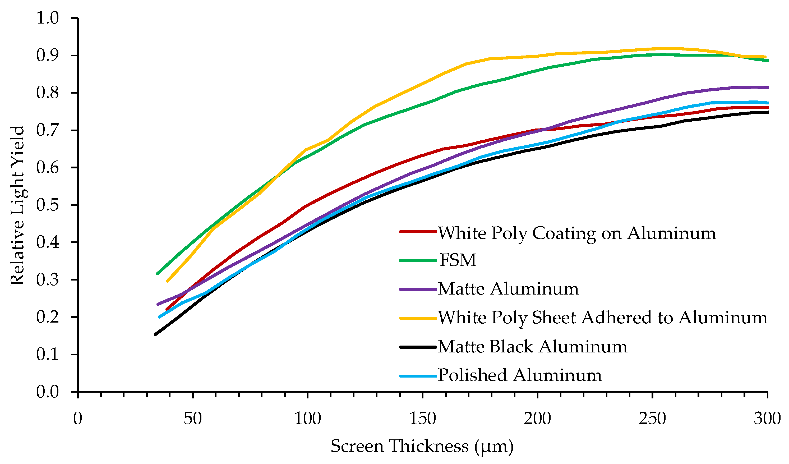
Figure 11 shows relative light yield as a function of screen thickness for the same 10B2O3(1:1)ZnS:Cu scintillator composition deposited on various substrates. Reflective materials such as white poly and a first surface mirror (FSM) increase light output because they simply reflect photons originally traveling away from the camera back toward the camera. However, photons reflected off the substrate undergo further diffusion in the scintillator material with the increased path-length, degrading the spatial resolution. The matte black backing absorbs photons so they do not reflect back and contribute to the image, which reduces light output but can improve spatial resolution. These measurements show that a reflective substrate can increase the relative light yield by > 20% compared to a matte black substrate.
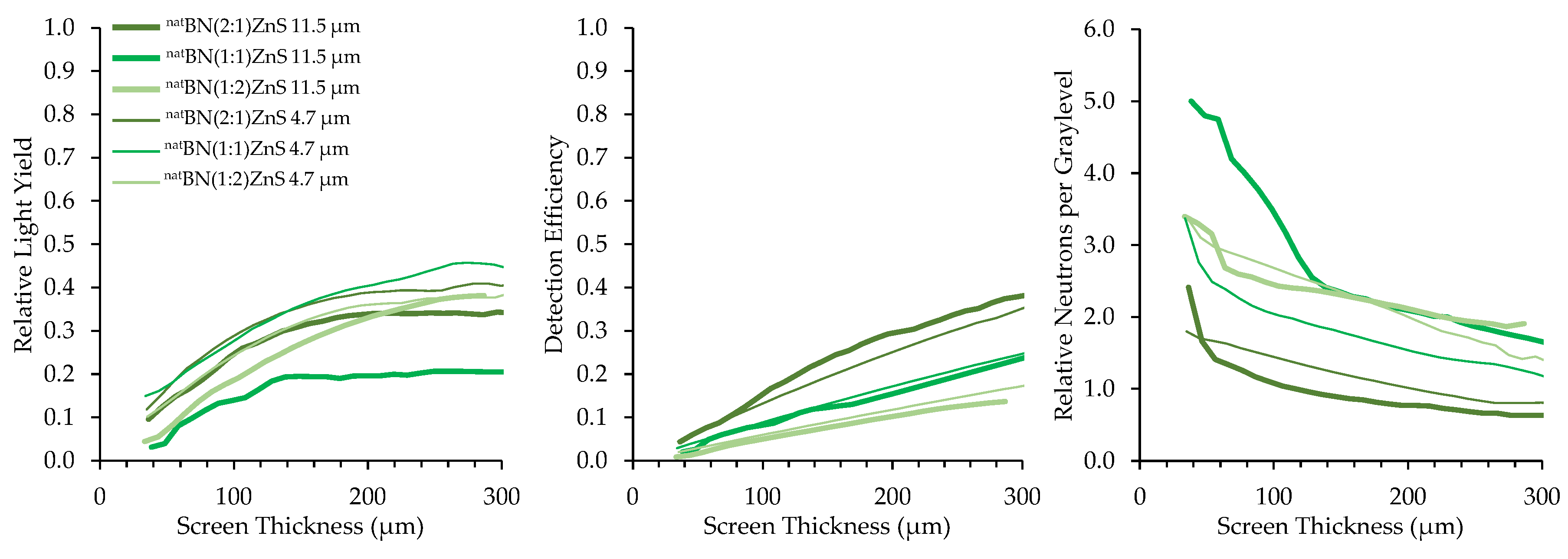
Converter materials of natBN, 10B2O3, and Na10B5O8 were mixed with ZnS:Cu scintillator material in B:ZnS atomic ratios of 2:1, 1:1, and 1:2. Results of borated screens with different converter materials, scintillator particles, and scintillator particle size are displayed in Figure 12, Figure 13 and Figure 14. All screens in these results were mounted on a matte black substrate to remove effects of photon reflection by the substrate.
Relative neutrons per graylevel, which is the ratio of the detection efficiency to the relative light yield, provides a measure of how many neutrons are represented in a grayscale value and a useful measure to compare screen performance. Detection efficiency scales with the amount of boron converter material, simply due to the increased macroscopic absorption cross-section of the converter–scintillator mixture. However, the screens with higher detection efficiency exhibited fewer photons produced per detected neutron because an increase in the amount of boron decreases the amount of phosphor material, inhibiting photon production.
Two sizes of scintillator particles, 11.5 and 4.7 μm, were used in the fabrication of the screens. However, there was not a consistent trend in the performance of screens with different sized scintillator particles. Detection efficiency was not affected by scintillator particle size because the bulk boron concentration of the mixture is independent of scintillator particle size. Optical examination did not reveal any differences in homogeneity between screens with different scintillator particle sizes.
A comparison of the performance of the different neutron converters with a 2:1 mix ratio, mounted to a polished aluminum substrate, is shown in Figure 15. 10B2O3 produced the highest light output while Na10B5O8 provided the best detection efficiency. The natBN contained unenriched boron, which explains its relatively poor performance compared to the other screens that used enriched 10B. However, based solely on the limited amount of 10B present in naturally occurring boron (19.9% 10B, 80.1% 11B), 10BN may be superior to 10B2O3 and Na10B5O8 if it were available for future testing.
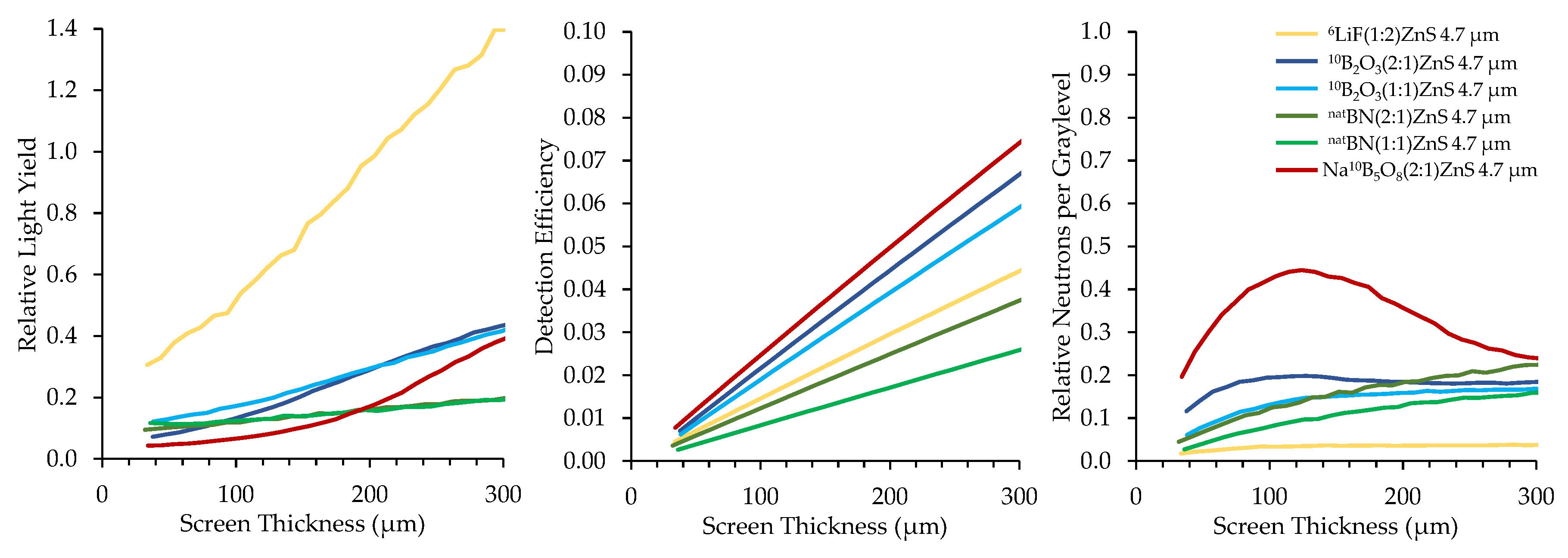
The top performing boron-based screens were compared with a 6LiF/ZnS:Cu screen comprised of a 1:2 (6LI:ZnS) mix ratio under cold neutron exposure, for which the results are summarized in Figure 16. All scintillator screens had a matte black backing.
The 6LiF-based screens produce significantly higher relative light yield than the boron-based screens, which is to be expected based on the higher reaction energy and longer range of 6Li’s daughter products. However, the boron-based screens exhibit a much higher detection efficiency than the 6Li-based screen, with some screens demonstrating 125% higher neutron detection efficiency for the same thickness. Their higher detection efficiency enables boron screens to provide improved neutron counting statistics, potentially accelerating image acquisition times proportionally to the improvement in detection efficiency.
The metric of relative neutrons per graylevel indicates that all boron-based scintillator screens correlate with improved neutron statistics compared to 6LiF screens. These measurements show that 6LiF screens are brighter, but the brightness is not caused by the detection of additional neutrons. Borated scintillator screens that are thinner than 6LiF could offer the same neutron detection efficiency but improved resolution. These results align with theoretical predictions and justify the further exploration of boron-based scintillators in neuron imaging applications.
3.2.2. Epithermal Neutron Results
The absorption cross-section of 10B is also higher than that of 6Li in the epithermal energy range, suggesting that 10B may exhibit superior performance in epithermal neutron imaging applications. Epithermal neutron imaging is useful when examining large, dense samples because epithermal neutrons have greater penetration than thermal neutrons, usually at the expense of contrast [52]. Epithermal neutron imaging is used to examine both archeological artifacts [53,54] as well as nuclear fuels [4,55], among other objects. The epithermal region, which overlaps with the resonance region, contains many absorption resonances for different materials. These resonances can be exploited using pulsed neutrons and time-of-flight techniques to determine the isotopic composition of a material [56]. Neutron scintillator screens with an improved detection efficiency for epithermal neutrons could also be useful in resonance imaging techniques [57,58,59].
In this work, a 1 mm-thick sheet of cadmium was placed in the neutron beam to absorb thermal neutrons, leaving primarily epithermal neutrons. Borated scintillator screen performance was measured under epithermal neutron exposure following the same procedure as with the unfiltered neutron beam. Figure 17 shows the top performing boron-based scintillators compared to a common 6LiF scintillator. The 6LiF scintillator exhibited superior light output compared to the borated screens under epithermal neutron exposure, as was the case with cold neutrons. However, the boron-based screens exhibit a much higher detection efficiency than the 6Li-based screen, with some screens exhibiting 67% higher epithermal neutron detection efficiency for the same thickness. Epithermal neutron tomography can take more than a day to acquire a full set of projections, but these results show that boron-based screens have the potential to reduce the time necessary for an epithermal neutron tomography by approximately 60%. Additionally, the relative neutrons per graylevel is significantly higher for the boron-based scintillators than for the 6LiF scintillator, which could indicate improved SNR for the images produced using the boron-based scintillators.
3.2.3. Spatial Resolution
Spatial resolution of the high-resolution boron screens was measured using the high-resolution imaging system at ANTARES. The effective pixel pitch of this system was 57 pixels/mm (17.5 µm/pixel), corresponding to a Nyquist frequency of 28.5 lp/mm. Figure 18 shows the MTF results for the high-resolution screens, which consisted of thinly deposited (10–20 μm) scintillator layers with 4.7 μm median scintillator particle size. The spatial resolution of all high resolution screens is displayed in Table 5 and the MTF curves of the top two performers, a layered 10B4C/ZnS screen and a natBN/ZnS screen, are displayed in Figure 18. Discrepancies in the spatial resolution for screens of the same material can be attributed to variations in the already the thin (≤20 μm) target scintillator layer thickness. At thin scintillator layers, a slight variation in the amount of deposited scintillator material or surface defects can drastically affect screen performance.
3.2.4. Neutron Computed Tomography
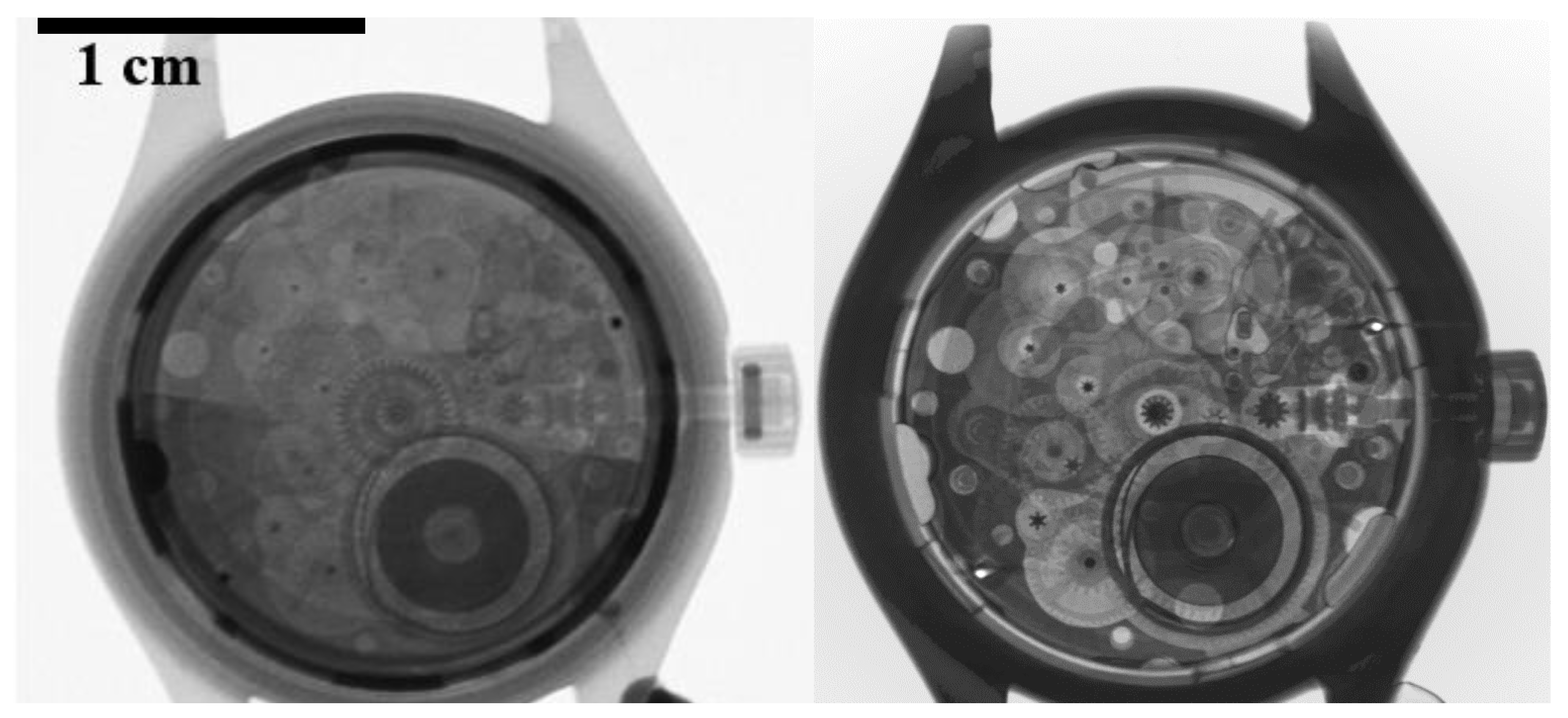
Radiographs were acquired with some of the high-resolution scintillator screens. These screens were chosen based on their promising performance, but also for the relatively uniform surface texture in the central field of view of the screens. Figure 19 (left) shows a radiograph of a small mechanical wristwatch acquired using a thin 10B2O3/ZnS:Cu screen. A set of 1229 radiographs was acquired for neutron computed tomography, and the resulting 3D rendering of the wristwatch is displayed in the right side of Figure 19. The mechanical gears inside the watch are clearly visible, demonstrating that these prototype screens are feasible to use in neutron radiography and tomography applications.
4. Discussion
Boron-based scintillator screens demonstrated superior neutron detection efficiency for both cold and epithermal neutron applications when compared to widely used 6LiF/ZnS neutron scintillator screens. Borated screens demonstrated up to 125% higher cold neutron detection efficiency and 67% higher epithermal neutron detection efficiency than representative 6LiF screens. Although borated screens produce less light output than representative 6LiF screens, the borated screens deliver improved neutron counting statistics compared to representative 6LiF screens. The higher neutron detection efficiency of boron-based screens offers the potential for higher quality neutron images and lower acquisition times. Epithermal neutron tomography acquisition time can potentially be reduced from days to hours, depending on the application.
Thin boron-based scintillator screens were measured to compare their spatial resolution performance. While some of the boron-based screens provided relatively high-resolution performance, the resolution performance was limited by the Nyquist limit of the imaging system employed in this study. Further measurements should be pursued using a neutron imaging system with a higher Nyquist limit to determine the spatial resolution potential of boron-based screens.
The top performing screens successfully produced a useful tomographic reconstruction of a test object. Boron-based screens may be able to deliver improved spatial resolution over common widely used screens based on the fundamental properties of the neutron absorption daughter products of 10B compared to those of 6Li. Provided an imaging setup has sufficient light sensitivity, boron-based neutron scintillators can provide improved neutron detection statistics. The higher neutron detection efficiency of boron-based screens stands to benefit the world-wide neutron imaging community by increasing neutron counting statistics and reducing measurement times.
Author Contributions
Conceptualization, W.C., A.C., S.C., and B.S.; methodology, W.C. and A.C.; formal analysis, W.C. and A.C.; investigation, W.C., A.C., B.S., A.T.; resources, S.C.; data curation, W.C.; writing—original draft preparation, W.C.; writing—review and editing, W.C., A.C., B.S., S.C. and A.T.; visualization, W.C.; supervision, A.C.; project administration, A.C.; funding acquisition, A.C. All authors have read and agreed to the published version of the manuscript.
Funding
Work funded through the INL Laboratory Directed Research & Development (LDRD) Program under DOE Idaho Operations Office Contract DE-AC07-05ID14517. LDRD Project ID# 20A44-200FP.
Acknowledgments
This work is based upon experiments performed at the ANTARES instrument operated by FRM II at Heinz Maier-Leibnitz Zentrum (MLZ), Garching, Germany. The authors would like to thank the FRM II staff as well as Amanda Smolinski for their assistance during the measurement process. DMI/Reading Imaging fabricated and prepared the various materials (e.g., the anhydrous 10B converter compounds and scintillators) and the coating formulations, fabricated the sensors used in this study, and measured the Na10B5O8 density.
Conflicts of Interest
The authors declare no conflict of interest.
References
- Lehmann, E.H.; Vontobel, P.; Hermann, A. Non-destructive analysis of nuclear fuel by means of thermal and cold neutrons. Nucl. Instrum. Methods Phys. Res. A 2003, 515, 745–759. [Google Scholar] [CrossRef]
- Sim, C.-M.; Kim, T.; Oh, H.S.; Kim, J.C. Measurement of Ballooning Gap Size of Irradiated Fuels Using Neutron Radiography Transfer Method and HV Image Filter. J. Korean Soc. Nondestruct. Test. 2013, 33, 212–218. [Google Scholar] [CrossRef] [Green Version]
- Tremsin, A.S.; Vogel, S.C.; Mocko, M.; Bourke, M.A.M.; Yuan, V.; Nelson, R.O.; Brown, D.W.; Feller, W.B. Non-destructive studies of fuel pellets by neutron resonance absorption radiography and thermal neutron radiography. J. Nucl. Mater. 2013, 440, 633–646. [Google Scholar] [CrossRef]
- Craft, A.E.; Wachs, D.M.; Okuniewski, M.A.; Chichester, D.L.; Williams, W.J.; Papaioannou, G.C.; Smolinski, A.T. Neutron Radiography of Irradiated Nuclear Fuel at Idaho National Laboratory. Phys. Procedia 2015, 69, 483–490. [Google Scholar] [CrossRef] [Green Version]
- Tremsin, A.S.; Craft, A.E.; Papaioannou, G.C.; Smolinski, A.T.; Boulton, N.M.; Ruddell, M.A.; Littell, B.J.; Riley, K.D. On the possibility to investigate irradiated fuel pins non-destructively by digital neutron radiography with a neutron-sensitive microchannel plate detector with Timepix readout. Nucl. Instrum. Methods Phys. Res. Sect. A Accel. Spectrometers Detect. Assoc. Equip. 2019, 927, 109–118. [Google Scholar] [CrossRef]
- Schulthess, J.; Woolstenhulme, N.; Craft, A.; Kane, J.; Boulton, N.; Chuirazzi, W.; Winston, A.; Smolinski, A.; Jensen, C.; Kamerman, D.; et al. Non-Destructive Post-irradiation Examination Results of the First Modern Fueled Experiments in TREAT. J. Nucl. Mater. 2020, 541, 152442. [Google Scholar] [CrossRef]
- Lehmann, E.H.; Vontobel, P.; Deschler-Erb, E.; Soares, M. Non-invasive studies of objects from cultural heritage. Nucl. Instrum. Methods Phys. Res. Sect. A Accel. Spectrometers Detect. Assoc. Equip. 2005, 42, 68–75. [Google Scholar] [CrossRef]
- Rant, J.; Milič, Z.; Istenič, J.; Knific, T.; Lengar, I.; Rant, A. Neutron radiography examination of objects belonging to the cultural heritage. Appl. Radiat. Isot. 2006, 64, 7–12. [Google Scholar] [CrossRef]
- Mannes, D.; Schmid, F.; Frey, J.; Schmidt-Ott, K.; Lehmann, E. Combined Neutron and X-ray Imaging for Non-invasive Investigations of Cultural Heritage Objects. Phys. Procedia 2015, 69, 653–660. [Google Scholar] [CrossRef] [Green Version]
- Iranzo, A.; Boillat, P.; Rosa, F. Validation of a three dimensional PEM fuel cell CFD model using local liquid water distributions measured with neutron imaging. Int. J. Hydrogen Energy 2014, 39, 7089–7099. [Google Scholar] [CrossRef]
- Makowska, M.G.; Strobl, M.; Lauridsen, E.M.; Frandsen, H.L.; Tremsin, A.S.; Kardjilov, N.; Manke, I.; Kelleher, J.F.; Theil Kuhn, L. Effect of stress on NiO reduction in solid oxide fuel cells: A new application of energy-resolved neutron imaging. J. Appl. Crystallogr. 2015, 48, 401–408. [Google Scholar] [CrossRef] [Green Version]
- Cochet, M.; Forner-Cuenca, A.; Manzi, V.; Siegwart, M.; Scheuble, D.; Boillat, P. Novel Concept for Evaporative Cooling of Fuel Cells: An Experimental Study Based on Neutron Imaging. Fuel Cells 2018, 18, 619–626. [Google Scholar] [CrossRef]
- Cho, J.I.S.; Neville, T.P.; Trogadas, P.; Meyer, Q.; Wu, Y.; Ziesche, R.; Boillat, P.; Cochet, M.; Manzi-Orezzoli, V.; Shearing, P.; et al. Visualization of liquid water in a lung-inspired flow-field based polymer electrolyte membrane fuel cell via neutron radiography. Energy 2019, 170, 14–21. [Google Scholar] [CrossRef]
- Kulkarni, N.; Meyer, Q.; Hack, J.; Jervis, R.; Iacoviello, F.; Ronaszegi, K.; Adcock, P.; Shearing, P.R.; Brett, D.J.L. Examining the effect of the secondary flow-field on polymer electrolyte fuel cells using X-ray computed radiography and computational modelling. Int. J. Hydrogen Energy 2019, 44, 1139–1150. [Google Scholar] [CrossRef]
- Koerner, S.; Schillinger, B.; Vontobel, P.; Rauch, H. A neutron tomography facility at a low power research reactor. Nucl. Instrum. Methods Phys. Res. Sect. A Accel. Spectrometers Detect. Assoc. Equip. 2001, 471, 69–74. [Google Scholar] [CrossRef]
- Sim, C.M.; Oh, H.S.; Kim, T.J.; Lee, Y.S.; Kim, Y.K.; Kwak, S.S.; Hwang, Y.H. Detecting Internal Hot Corrosion of In-service Turbine Blades Using Neutron Tomography with Gd Tagging. J. Nondestruct. Eval. 2014, 33, 493–503. [Google Scholar] [CrossRef]
- Peetermans, S.; Lehmann, E.H. Simultaneous neutron transmission and diffraction imaging investigations of single crystal nickel-based superalloy turbine blades. NDT E Int. 2016, 79, 109–113. [Google Scholar] [CrossRef]
- Lehmann, E.H. Neutron imaging facilities in a global context. J. Imaging 2017, 3, 52. [Google Scholar] [CrossRef] [Green Version]
- Stedman, R. Scintillator for thermal neutrons using Li6F and ZnS (Ag). Rev. Sci. Instrum. 1960, 31, 1156. [Google Scholar] [CrossRef]
- Mantler-Niederstätter, F.; Bensch, F.; Grass, F. An extremely thin scintillation detector for thermal neutrons. Nucl. Instrum. Methods 1977, 142, 463–466. [Google Scholar] [CrossRef]
- Knoll, G.F. Radiation Detection and Measurements, 3rd ed.; Wiley and Sons: Hoboken, NJ, USA, 2000; ISBN 0471073385. [Google Scholar]
- Katagiri, M.; Sakasai, K.; Matsubayashi, M.; Nakamura, T.; Kondo, Y.; Chujo, Y.; Nanto, H.; Kojima, T. Scintillation materials for neutron imaging detectors. Nucl. Instrum. Methods Phys. Res. A 2004, 529, 274–279. [Google Scholar] [CrossRef]
- Crha, J.; Vila-Comamala, J.; Lehmann, E.; David, C.; Trtik, P. Light Yield Enhancement of 157-Gadolinium Oxysulfide Scintillator Screens for the High-Resolution Neutron Imaging. MethodsX 2019, 6, 107–114. [Google Scholar] [CrossRef] [PubMed]
- Sun, K.H.; Malmberg, P.R.; Pecjak, F.A. High-Efficiency Slow-Neutron Scintillation Counters. Nucleonics 1956, 14, 46–49. [Google Scholar]
- McGonnagle, W.J. Symposium on Physics and Nondestructive Testing; Argonne National Laboratory: Argonne, IL, USA, 1960; ANL-6346.
- Kojima, T.; Katagiri, M.; Tsutsui, N.; Imai, K.; Matsubayashi, M.; Sakasai, K. Neutron scintillators with high detection efficiency. Nucl. Instrum. Methods Phys. Res. Sect. A Accel. Spectrometers Detect. Assoc. Equip. 2004, 529, 325–328. [Google Scholar] [CrossRef]
- Katagiri, M.; Sakasai, K.; Matsubayashi, M.; Kojima, T. Neutron/γ-ray discrimination characteristics of novel neutron scintillators. Nucl. Instrum. Methods Phys. Res. Sect. A Accel. Spectrometers Detect. Assoc. Equip. 2004, 529, 317–320. [Google Scholar] [CrossRef]
- Ishii, M.; Kuwano, Y.; Asai, T.; Asaba, S.; Kawamura, M.; Senguttuvan, N. Boron based oxide scintillation glass for neutron detection. Nucl. Instrum. Methods Phys. Res. A Accel. Spectrometers Detect. Assoc. Equip. 2005, 537, 282–285. [Google Scholar] [CrossRef]
- Czirr, J.B.; Macgillivray, G.M.; Macgillivray, R.R.; Seddon, P.J. Performance and characteristics of a new scintillator. Nucl. Instrum. Methods Phys. Res. Sect. Accel. Spectrometers Detect. Assoc. Equip. 1999, 424, 15–19. [Google Scholar] [CrossRef]
- Williams, A.M.; Beeley, P.A.; Spyrou, N.M. Response of a lithium gadolinium borate scintillator in monoenergetic neutron fields. Radiat. Prot. Dosim. 2004, 110, 497–502. [Google Scholar] [CrossRef]
- Normand, S.; Mouanda, B.; Haan, S.; Louvel, M. Discrimination methods between neutron and gamma rays for boron loaded plastic scintillators. Nucl. Instrum. Methods Phys. Res. Sect. A Accel. Spectrometers Detect. Assoc. Equip. 2002, 484, 342–350. [Google Scholar] [CrossRef]
- Britvich, G.I.; Vasil’chenko, V.G.; Gilitsky, Y.V.; Chubenko, A.P.; Kushnirenko, A.E.; Mamidzhanyan, E.A.; Pavluchenko, V.P.; Pikalov, V.A.; Romakhin, V.A.; Soldatov, A.P.; et al. A neutron detector on the basis of a boron-containing plastic scintillator. Nucl. Instrum. Methods Phys. Res. Sect. A Accel. Spectrometers Detect. Assoc. Equip. 2005, 550, 343–358. [Google Scholar] [CrossRef]
- Mahl, A.; Yemam, H.A.; Stuntz, J.; Remedes, T.; Sellinger, A.; Greife, U. Bis(pinacolato)diboron as an additive for the detection of thermal neutrons in plastic scintillators. Nucl. Instrum. Methods Phys. Res. A 2016, 816, 96–100. [Google Scholar] [CrossRef] [Green Version]
- Mahl, A.; Yemam, H.A.; Fernando, R.; Koubek, J.T.; Sellinger, A. 10B enriched plastic scintillators for application in thermal neutron detection. Nucl. Inst. Methods Phys. Res. A 2018, 880, 1–5. [Google Scholar] [CrossRef]
- Verhaeghe, J.L.; Thielens, G.; Creten, W.L. Preparation and properties of a boron containing scintillator for the detection of slow neutrons. Appl. Sci. Res. Sect. B 1962, 10, 247–256. [Google Scholar] [CrossRef]
- Brenizer, J.S.; Berger, H.; Stebbings, C.T.; Gillies, G.T. Performance characteristics of scintillators for use in an electronic neutron imaging system for neutron radiography. Rev. Sci. Instrum. 1997, 68, 3371–3379. [Google Scholar] [CrossRef]
- McMillan, J.E.; Cole, A.J.; Kirby, A.; Marsden, E. Thermal neutron scintillators using unenriched boron nitride and zinc sulfide. J. Phys. Conf. Ser. 2015, 620, 012011. [Google Scholar] [CrossRef] [Green Version]
- Nakamura, T.; Katagiri, M.; Tsutsui, N.; Toh, K.; Rhodes, N.; Schooneveld, E.; Ooguri, H.; Noguchi, Y.; Sakasai, K.; Soyama, K. Development of a ZnS/10B2O3 scintillator with low- afterglow phosphor Development of a ZnS/10B2O3 scintillator with low-afterglow phosphor. Int. Work. Neutron Opt. Detect. 2014, 528, 1–8. [Google Scholar]
- Miller, S.R.; Marshall, M.S.J.; Wart, M.; Crha, J.; Trtik, P.; Nagarkar, V.V. High Resolution Thermal Neutron Imaging with 10Boron/CsI:Tl Scintillator Screen. IEEE Trans. Nucl. Sci. 2020, 9499, 1–5. [Google Scholar]
- Van Delinder, K.W.; Khan, R.; Gräfe, J.L. Neutron activation of gadolinium for ion therapy: A Monte Carlo study of charged particle beams. Sci. Rep. 2020, 10, 1–11. [Google Scholar] [CrossRef]
- Miller, G.A.; Hertel, N.E.; Wehring, B.W.; Horton, J.L. Gadolinium neutron capture therapy. Nucl. Technol. 1993, 103, 320–331. [Google Scholar] [CrossRef]
- Kandlakunta, P.; Cao, L.R.; Mulligan, P. Measurement of internal conversion electrons from Gd neutron capture. Nucl. Instrum. Methods Phys. Res. Sect. A Accel. Spectrometers Detect. Assoc. Equip. 2013, 705, 36–41. [Google Scholar] [CrossRef]
- Goorley, T.; Nikjoo, H. Electron and photon spectra for three gadolinium-based cancer therapy approaches. Radiat. Res. 2000, 154, 556–563. [Google Scholar] [CrossRef]
- Abdushukurov, D.A.; Abduvokhldov, M.A.; Bondarenko, D.V.; Mumlnov, K.K.; Toshov, T.A.; Chlstyakov, D.Y. Modeling the registration efficiency of thermal neutrons by gadolinium foils. J. Instrum. 2007, 2, 04001. [Google Scholar] [CrossRef] [Green Version]
- Berger, M.J.; Coursey, J.S.; Zucker, M.A.; Chang, J. Stopping-Power and Range Tables For Electrons, Protons, and Helium Ions; NIST Physics Laboratory: Gaithersburg, MD, USA, 2017.
- Ziegler, J.F.; Ziegler, M.D.; Biersack, J.P. SRIM-The stopping and range of ions in matter (2010). Nucl. Instrum. Methods Phys. Res. Sect. B Beam Interact. Mater. Atoms 2010, 268, 1818–1823. [Google Scholar] [CrossRef] [Green Version]
- Salvat, F.; Fernandez-Varea, J.M.; Sempau, J. PENELOPE-2006: A code system for Monte Carlo simulation of electron and photon transport. Work. Proc. 2006, 4, 6222. [Google Scholar]
- Detail Information of NaB5H10O1; Catalyst Hub. Available online: http://www.catalysthub.net/materials.php?id=1830324,2016 (accessed on 27 October 2020).
- Chuirazzi, W.; Craft, A. Measuring Thickness-Dependent Relative Light Yield and Detection Efficiency of Scintillator Screens. J. Imaging 2020, 6, 56. [Google Scholar] [CrossRef]
- Schulz, M.; Schillinger, B. ANTARES: Cold neutron radiography and tomography facility. J. Large-Scale Res. Facil. JLSRF 2015, 1, 8–11. [Google Scholar] [CrossRef] [Green Version]
- Andor, iKon-L Series iKon-L Series. Available online: https://andor.oxinst.com/products/ikon-xl-and-ikon-large-ccd-series/ikon-l-936 (accessed on 12 February 2020).
- Schillinger, B.; Craft, A.E. Epithermal Neutron Radiography and Tomography on Large and Strongly Scattering Samples. Mater. Res. Proc. 2020, 15, 142–148. [Google Scholar]
- Schooneveld, E.M.; Tardocchi, M.; Gorini, G.; Kockelmann, W.; Nakamura, T.; Perelli Cippo, E.; Postma, H.; Rhodes, N.; Schillebeeckx, P. A new position-sensitive transmission detector for epithermal neutron imaging. J. Phys. D Appl. Phys. 2009, 42, 152003. [Google Scholar] [CrossRef]
- Cippo, E.P.; Borella, A.; Gorini, G.; Kockelmann, W.; Moxon, M.; Postma, H.; Rhodes, N.J.; Schillebeeckx, P.; Schoonenveld, E.M.; Tardocchi, M.; et al. Imaging of cultural heritage objects using neutron resonances. J. Anal. At. Spectrom. 2011, 26, 992–999. [Google Scholar] [CrossRef]
- Vogel, S.C. A Review of Neutron Scattering Applications to Nuclear Materials. ISRN Mater. Sci. 2013, 2013, 1–24. [Google Scholar] [CrossRef] [Green Version]
- Vogel, S.C.; Bourke, M.A.M.; Craft, A.E.; Harp, J.M.; Kelsey, C.T.; Lin, J.; Long, A.M.; Losko, A.S.; Hosemann, P.; McClellan, K.J.; et al. Advanced Postirradiation Characterization of Nuclear Fuels Using Pulsed Neutrons. Jom 2020, 72, 187–196. [Google Scholar] [CrossRef]
- Tremsin, A.S.; McPhate, J.B.; Vallerga, J.V.; Siegmund, O.H.W.; Kockelmann, W.; Schooneveld, E.M.; Rhodes, N.J.; Bruce Feller, W. High resolution neutron resonance absorption imaging at a pulsed neutron beamline. IEEE Trans. Nucl. Sci. 2012, 59, 3272–3277. [Google Scholar] [CrossRef]
- Tremsin, A.S.; Kockelmann, W.; Pooley, D.E.; Feller, W.B. Spatially resolved remote measurement of temperature by neutron resonance absorption. Nucl. Instrum. Methods Phys. Res. Sect. A Accel. Spectrometers Detect. Assoc. Equip. 2015, 803, 15–23. [Google Scholar] [CrossRef] [Green Version]
- Dangendorf, V.; Laczko, G.; Kersten, C. Fast neutron resonance radiography in a pulsed neutron beam. arXiv 2003, arXiv:nucl-ex/0301001v1. [Google Scholar]
Figure 1.
Microscopic absorption cross-section of 10B and 6Li from the Evaluated Nuclear Data File (ENDF/B-VIII) cross-section libraries.
Figure 1.
Microscopic absorption cross-section of 10B and 6Li from the Evaluated Nuclear Data File (ENDF/B-VIII) cross-section libraries.

Figure 2.
Transmission of Ions in Matter (TRIM) simulated daughter product path length in various converter materials. The 10B(n,α)7Li daughter products deposit their energy more locally than the 6Li(n,α)3H daughter products. This demonstrates that 10B-based scintillators offer an improved theoretical spatial resolution limit compared to 6Li-based screens.

Figure 3.
Calculated attenuation fraction for the thermal (top) and cold neutrons (bottom) in different scintillator materials.
Figure 3.
Calculated attenuation fraction for the thermal (top) and cold neutrons (bottom) in different scintillator materials.

Figure 4.
Schematic of a wedged scintillator concept [49].
Figure 4.
Schematic of a wedged scintillator concept [49].

Figure 5.
Photograph of a wedged scintillator screen with an oblique light applied to enhance the appearance of the surface texture. The screen shown is a 10B2O3 neutron converter in a 1:1 (10B:ZnS) mix ratio with a ZnS:Cu scintillator with 11.5 μm median particle size.
Figure 5.
Photograph of a wedged scintillator screen with an oblique light applied to enhance the appearance of the surface texture. The screen shown is a 10B2O3 neutron converter in a 1:1 (10B:ZnS) mix ratio with a ZnS:Cu scintillator with 11.5 μm median particle size.
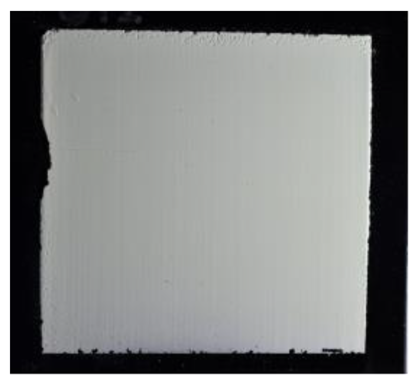
Figure 6.
Photograph of a double-wedged scintillator screen consisting of a boron carbide converter (10B4C) and a ZnS:Cu scintillator with 11.5 μm median particle size.
Figure 6.
Photograph of a double-wedged scintillator screen consisting of a boron carbide converter (10B4C) and a ZnS:Cu scintillator with 11.5 μm median particle size.
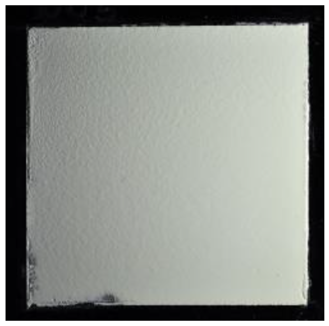
Figure 7.
Photograph of a high-resolution scintillator screen consisting of a 10B2O3 neutron converter in a 1:1 (10B:ZnS) mix ratio with a ZnS:Cu scintillator with 4.7 μm median particle size.
Figure 7.
Photograph of a high-resolution scintillator screen consisting of a 10B2O3 neutron converter in a 1:1 (10B:ZnS) mix ratio with a ZnS:Cu scintillator with 4.7 μm median particle size.

Figure 8.
Schematic diagram showing the light yield measurement of the borated screens (left). A representative radiograph showing the light output from four borated screens (right).
Figure 8.
Schematic diagram showing the light yield measurement of the borated screens (left). A representative radiograph showing the light output from four borated screens (right).
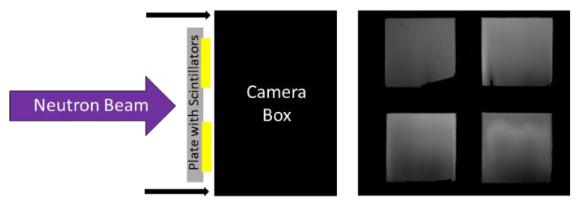
Figure 9.
Schematic diagram of the detection efficiency measurement (left) and a representative radiograph of four borated screens obtained with this setup (right).
Figure 9.
Schematic diagram of the detection efficiency measurement (left) and a representative radiograph of four borated screens obtained with this setup (right).

Figure 10.
The measured relative light output of borated neutron scintillator screens from the initial scoping studies.
Figure 10.
The measured relative light output of borated neutron scintillator screens from the initial scoping studies.
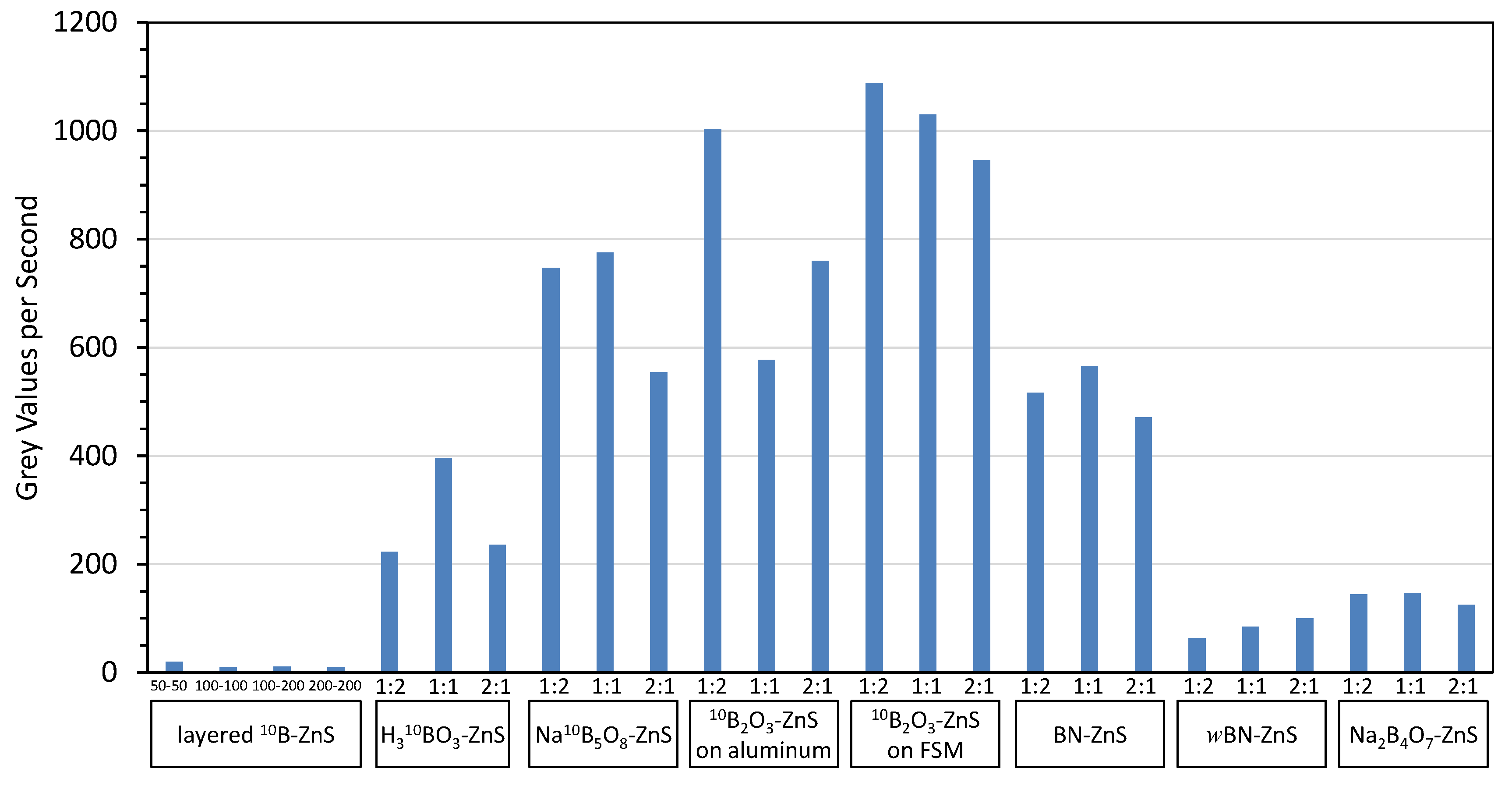
Figure 11.
Relative light yield as a function of thickness for a 10B2O3(1:1)ZnS:Cu scintillator composition deposited onto various substrates.
Figure 11.
Relative light yield as a function of thickness for a 10B2O3(1:1)ZnS:Cu scintillator composition deposited onto various substrates.

Figure 12.
Results for 10B2O3 screens with different mix ratios and scintillator particle sizes.

Figure 13.
Results for natBN screens with different mix ratios and scintillator particle sizes.

Figure 14.
Results for Na10B5O8 screens with different mix ratios and scintillator particle sizes.
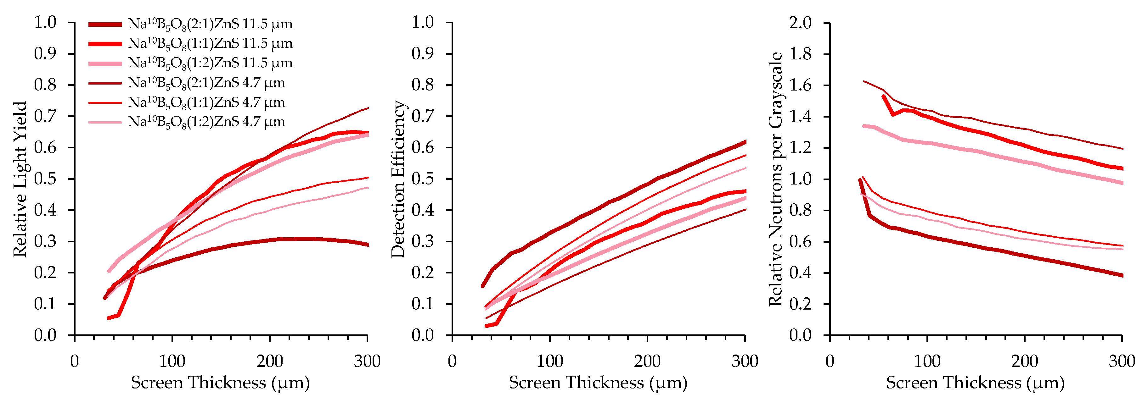
Figure 15.
Results for neutron scintillator screens with different neutron converters.
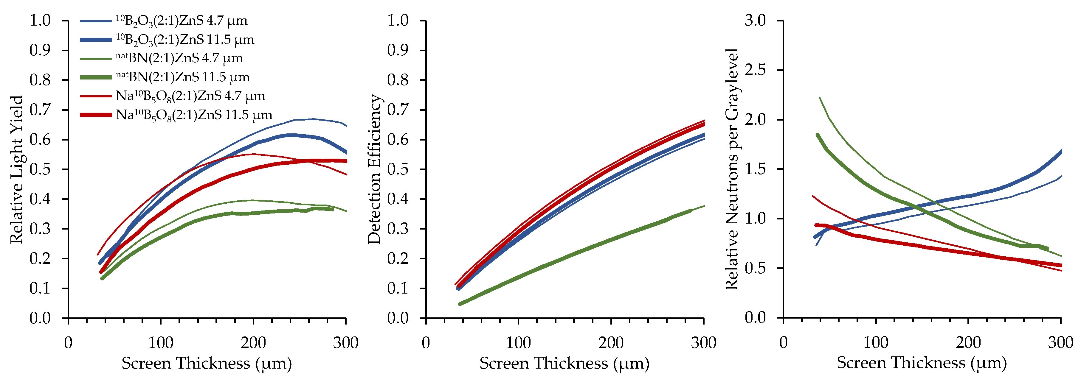
Figure 16.
Top-performing boron-based screens under a cold neutron beam compared to a 6LiF:ZnS screen.
Figure 16.
Top-performing boron-based screens under a cold neutron beam compared to a 6LiF:ZnS screen.
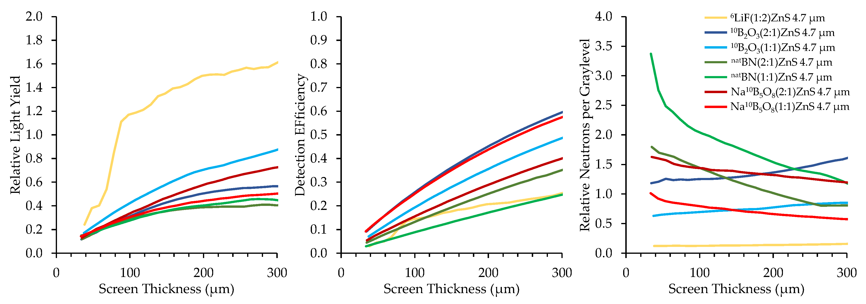
Figure 17.
Top-performing boron-based screens under an epithermal neutron beam compared to a 6LiF:ZnS screen.
Figure 17.
Top-performing boron-based screens under an epithermal neutron beam compared to a 6LiF:ZnS screen.

Figure 18.
MTF curves of high-resolution scintillators with the best spatial resolution. The boron carbide screen is layered with ZnS, while the boron nitride screen is mixed with the ZnS scintillator.
Figure 18.
MTF curves of high-resolution scintillators with the best spatial resolution. The boron carbide screen is layered with ZnS, while the boron nitride screen is mixed with the ZnS scintillator.
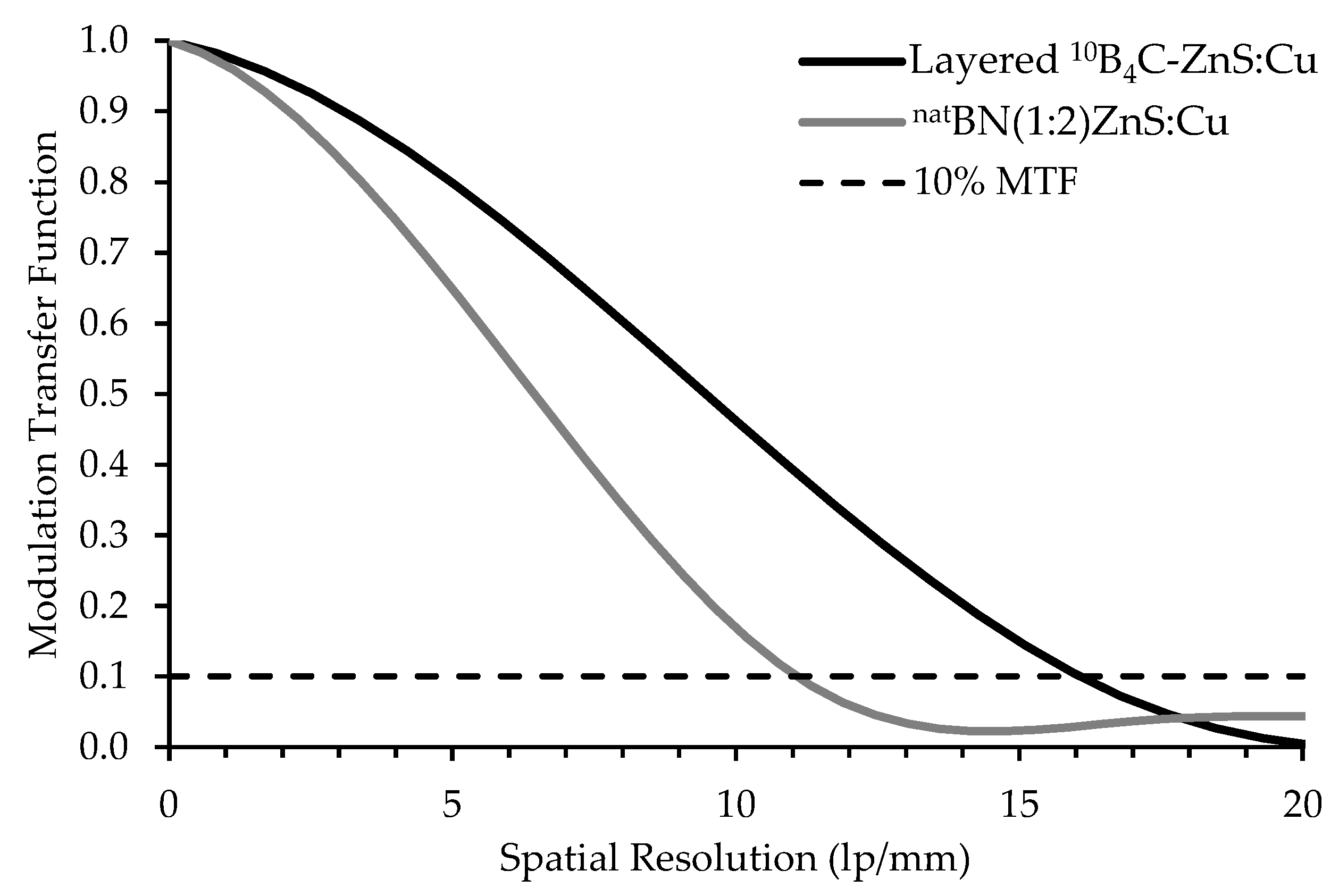
Figure 19.
A neutron radiograph (left) and a cut-away of a 3D tomographic reconstruction (right) of a mechanical wristwatch.
Figure 19.
A neutron radiograph (left) and a cut-away of a 3D tomographic reconstruction (right) of a mechanical wristwatch.


Table 1.
Simulated converter daughter product range in converter medium.
| Converter | Density (g/cm3) | Daughter Product Range | |||
|---|---|---|---|---|---|
| 7Li (1.01 MeV) | α (1.78 MeV) | 7Li (0.84 MeV) | α (1.47 MeV) | ||
| B2O3 | 2.46 | 2.45 µm | 4.84 µm | 2.19 µm | 3.97 µm |
| NaB5O8 | 2.06 | 2.98 µm | 5.88 µm | 2.66 µm | 4.82 µm |
| BN | 2.10 | 2.61 µm | 5.21 µm | 2.34 µm | 4.24 µm |
| 3H (2.73 MeV) | α (2.05 MeV) | ||||
| LiF | 2.64 | 62.7 µm | 6.04 µm | ||
| ICe− (29 keV) | ICe− (71 keV) | ||||
| 157Gd2O2S:Tb | 7.32 | 1.31 µm | 5.46 µm | ||
Table 2.
Total macroscopic cross-section, mean free path, and the 20% absorption thickness of different borated scintillator screens compared to 6LiF and GOS screens.
Table 2.
Total macroscopic cross-section, mean free path, and the 20% absorption thickness of different borated scintillator screens compared to 6LiF and GOS screens.
| Scintillator Mixture | Σtotal | Mean Free Path (µm) | 20% Absorption Thickness (µm) | |||
|---|---|---|---|---|---|---|
| (cm−1) | ||||||
| Thermal | Cold | Thermal | Cold | Thermal | Cold | |
| 6LiF:ZnS (1:2) | 12.8 | 28.5 | 780 | 350 | 174 | 78 |
| natBN:ZnS (1:1) | 14.3 | 32.0 | 700 | 313 | 156 | 70 |
| 6LiF:ZnS (1:1) | 17.8 | 39.7 | 562 | 252 | 125 | 56 |
| Na10B5O8:ZnS (1:1) | 41.5 | 92.4 | 241 | 108 | 54 | 24 |
| 10B2O3:ZnS (1:1) | 52.9 | 118 | 189 | 85 | 42 | 19 |
| 10BN:ZnS (1:1) | 69.6 | 156 | 144 | 64 | 32 | 14 |
| Gd2O2S (Gadox) | 799 | 1467 | 13 | 6.8 | 2.8 | 1.5 |
Table 3.
Parameters of screens used in initial scoping studies.
| Substrate | Converter Material | Atomic Ratio (B:ZnS) | Thickness (µm) |
|---|---|---|---|
| Aluminum | 10B-enriched boron powder | layered | 5050 |
| Aluminum | 10B-enriched boron powder | layered | 100,100 |
| Aluminum | 10B-enriched boron powder | layered | 200,100 |
| Aluminum | 10B-enriched boron powder | layered | 200,200 |
| Aluminum | 10B-enriched Boric Acid | 2:1 | 200 |
| Aluminum | 10B-enriched Boric Acid | 1:1 | 200 |
| Aluminum | 10B-enriched Boric Acid | 1:2 | 200 |
| Aluminum | 10B-enr. Sodium Pentaborate | 2:1 | 200 |
| Aluminum | 10B-enr. Sodium Pentaborate | 1:1 | 200 |
| Aluminum | 10B-enr. Sodium Pentaborate | 1:2 | 200 |
| Aluminum | Boron Oxide (B2O3) | 2:1 | 200 |
| Aluminum | Boron Oxide (B2O3) | 1:1 | 200 |
| Aluminum | Boron Oxide (B2O3) | 1:2 | 200 |
| 1.9 mm FSM | Boron Oxide (B2O3) | 2:1 | 200 |
| 1.9 mm FSM | Boron Oxide (B2O3) | 1:1 | 200 |
| 1.9 mm FSM | Boron Oxide (B2O3) | 1:2 | 200 |
| Aluminum | Boron Nitride (BN) | 2:1 | 200 |
| Aluminum | Boron Nitride (BN) | 1:1 | 200 |
| Aluminum | Boron Nitride (BN) | 1:2 | 200 |
| Aluminum | Wurtzite-Boron Nitride (w-BN) | 2:1 | 200 |
| Aluminum | Wurtzite-Boron Nitride (w-BN) | 1:1 | 200 |
| Aluminum | Wurtzite-Boron Nitride (w-BN) | 1:2 | 200 |
| Aluminum | Anhydrous Sodium Tetraborate | 2:1 | 200 |
| Aluminum | Anhydrous Sodium Tetraborate | 1:1 | 200 |
| Aluminum | Anhydrous Sodium Tetraborate | 1:2 | 200 |
Table 4.
Scintillator screen parameter combinations of second testing phase.
| Particle Size (µm) | Phosphor Maximum Thickness | Converter Material | Converter Thickness (µm) | Converter to Scintillator At. Ratio (B:ZnS) | Converter to Scintillator Weight Ratio | Substrate Surface Finish | Notes |
|---|---|---|---|---|---|---|---|
| 11.5 | 300 | 10B metal | 100 | - | - | matte black | double Wedge |
| 4.7 | 300 | 10B metal | 100 | - | - | matte black | double Wedge |
| 11.5 | 300 | 10B4C | 100 | - | - | matte black | double Wedge |
| 4.7 | 300 | 10B4C | 100 | - | - | matte black | double Wedge |
| 11.5 | 300 | 10B2O3 | - | 2:1 | 1:2.5 | matte black | single wedge |
| 11.5 | 300 | 10B2O3 | - | 1:1 | 1:4 | matte black | single wedge |
| 11.5 | 300 | 10B2O3 | - | 1:2 | 1:7 | matte black | single wedge |
| 4.7 | 300 | 10B2O3 | - | 2:1 | 1:2.5 | matte black | single wedge |
| 4.7 | 300 | 10B2O3 | - | 1:1 | 1:4 | matte black | single wedge |
| 4.7 | 300 | 10B2O3 | - | 1:2 | 1:7 | matte black | single wedge |
| 11.5 | 300 | Na10B5O8 | - | 2:1 | 1:2.3 | matte black | single wedge |
| 11.5 | 300 | Na10B5O8 | - | 1:1 | 1:3.5 | matte black | single wedge |
| 11.5 | 300 | Na10B5O8 | - | 1:2 | 1:6.1 | matte black | single wedge |
| 4.7 | 300 | Na10B5O8 | - | 2:1 | 1:2.3 | matte black | single wedge |
| 4.7 | 300 | Na10B5O8 | - | 1:1 | 1:3.5 | matte black | single wedge |
| 4.7 | 300 | Na10B5O8 | - | 1:2 | 1:6.1 | matte black | single wedge |
| 11.5 | 300 | natBN | - | 2:1 | 1:3.1 | matte black | single wedge |
| 11.5 | 300 | natBN | - | 1:1 | 1:5.1 | matte black | single wedge |
| 11.5 | 300 | natBN | - | 1:2 | 1:9.2 | matte black | single wedge |
| 4.7 | 300 | natBN | - | 2:1 | 1:3.1 | matte black | single wedge |
| 4.7 | 300 | natBN | - | 1:1 | 1:5.1 | matte black | single wedge |
| 4.7 | 300 | natBN | - | 1:2 | 1:9.2 | matte black | single wedge |
| 11.5 | 300 | 10B2O3 | - | 2:1 | 1:2.5 | polished | single wedge |
| 11.5 | 300 | 10B2O3 | - | 1:1 | 1:4 | polished | single wedge |
| 11.5 | 300 | 10B2O3 | - | 1:2 | 1:7 | polished | single wedge |
| 4.7 | 300 | 10B2O3 | - | 2:1 | 1:2.5 | polished | single wedge |
| 4.7 | 300 | 10B2O3 | - | 1:1 | 1:4 | polished | single wedge |
| 4.7 | 300 | 10B2O3 | - | 1:2 | 1:7 | polished | single wedge |
| 11.5 | 300 | Na10B5O8 | - | 2:1 | 1:2.3 | polished | single wedge |
| 11.5 | 300 | Na10B5O8 | - | 1:1 | 1:3.5 | polished | single wedge |
| 11.5 | 300 | Na10B5O8 | - | 1:2 | 1:6.1 | polished | single wedge |
| 4.7 | 300 | Na10B5O8 | - | 2:1 | 1:2.3 | polished | single wedge |
| 4.7 | 300 | Na10B5O8 | - | 1:1 | 1:3.5 | polished | single wedge |
| 4.7 | 300 | Na10B5O8 | - | 1:2 | 1:6.1 | polished | single wedge |
| 11.5 | 300 | natBN | - | 2:1 | 1:3.1 | polished | single wedge |
| 11.5 | 300 | natBN | - | 1:1 | 1:5.1 | polished | single wedge |
| 11.5 | 300 | natBN | - | 1:2 | 1:9.21 | polished | single wedge |
| 4.7 | 300 | natBN | - | 2:1 | 1:3.1 | polished | single wedge |
| 4.7 | 300 | natBN | - | 1:1 | 1:5.1 | polished | single wedge |
| 4.7 | 300 | natBN | - | 1:2 | 1:9.2 | polished | single wedge |
| 11.5 | 300 | 10B2O3 | - | 1:1 | 1:4 | white poly coating | single wedge |
| 11.5 | 300 | 10B2O3 | - | 1:1 | 1:4 | FSM | single wedge |
| 11.5 | 300 | 10B2O3 | - | 1:1 | 1:4 | matte | single wedge |
| 11.5 | 300 | 6LiF | - | 1:2 | 1:9.2 | matte black | single wedge |
| 6.7 | 300 | 6LiF | - | 1:2 | 1:9.2 | matte black | single wedge |
| 4.7 | 300 | 6LiF | - | 1:2 | 1:9.2 | matte black | single wedge |
| 11.5 | 300 | 6LiF | - | 1:2 | 1:9.2 | matte | single wedge |
| 6.7 | 300 | 6LiF | - | 1:2 | 1:9.2 | matte | single wedge |
| 4.7 | 300 | 6LiF | - | 1:2 | 1:9.2 | matte | single wedge |
| 11.5 | 300 | 10B2O3 | - | 1:1 | 1:4 | white poly sheet | single wedge |
| 4.7 | 20 | 10B2O3 | - | 2:1 | 1:2.5 | matte black | |
| 4.7 | 20 | 10B2O3 | - | 1:1 | 1:4 | matte black | |
| 4.7 | 20 | 10B2O3 | - | 1:2 | 1:7 | matte black | |
| 4.7 | 20 | Na10B5O8 | - | 2:1 | 1:2.3 | matte black | |
| 4.7 | 20 | Na10B5O8 | - | 1:1 | 1:3.5 | matte black | |
| 4.7 | 20 | Na10B5O8 | - | 1:2 | 1:6.1 | matte black | |
| 4.7 | 20 | natBN | - | 2:1 | 1:5.7 | matte black | |
| 4.7 | 20 | natBN | - | 1:1 | 1:10.4 | matte black | |
| 4.7 | 20 | natBN | - | 1:2 | 1:19.9 | matte black | |
| 4.7 | 20 | pure 10B | 10 | - | - | matte black | layered |
| 4.7 | 20 | 10B4C | 10 | - | - | matte black | layered |
Table 5.
Effective spatial resolution for uniform thickness screens.
| Converter Material | Converter to Scintillator Atomic Ratio (Boron atom to ZnS:Cu) | Resolution at 10% Modulation Transfer Function (MTF) (lp/mm) |
|---|---|---|
| 10B2O3 | 2:1 | 10.6 |
| 10B2O3 | 2:1 | 7.6 |
| 10B2O3 | 1:1 | 9.6 |
| 10B2O3 | 1:1 | 9.6 |
| 10B2O3 | 1:2 | 7.4 |
| 10B2O3 | 1:2 | 7.3 |
| 10NaB5O8 | 2:1 | 10.5 |
| 10NaB5O8 | 2:1 | 8.8 |
| 10NaB5O8 | 1:1 | 10.2 |
| 10NaB5O8 | 1:1 | 9.9 |
| 10NaB5O8 | 1:2 | 7.6 |
| 10NaB5O8 | 1:2 | 8.2 |
| natBN | 2:1 | 4.8 |
| natBN | 2:1 | 9.7 |
| natBN | 1:1 | 8.3 |
| natBN | 1:1 | 6.7 |
| natBN | 1:2 | 6.6 |
| natBN | 1:2 | 15.2 |
| Layered 10B4C | 10 μm 10B4C, 20 μm ZnS:Cu | 16.0 |
Publisher’s Note: MDPI stays neutral with regard to jurisdictional claims in published maps and institutional affiliations. |
© 2020 by the authors. Licensee MDPI, Basel, Switzerland. This article is an open access article distributed under the terms and conditions of the Creative Commons Attribution (CC BY) license (http://creativecommons.org/licenses/by/4.0/).
Share and Cite
MDPI and ACS Style
Chuirazzi, W.; Craft, A.; Schillinger, B.; Cool, S.; Tengattini, A. Boron-Based Neutron Scintillator Screens for Neutron Imaging. J. Imaging 2020, 6, 124. https://0-doi-org.brum.beds.ac.uk/10.3390/jimaging6110124
AMA Style
Chuirazzi W, Craft A, Schillinger B, Cool S, Tengattini A. Boron-Based Neutron Scintillator Screens for Neutron Imaging. Journal of Imaging. 2020; 6(11):124. https://0-doi-org.brum.beds.ac.uk/10.3390/jimaging6110124
Chicago/Turabian StyleChuirazzi, William, Aaron Craft, Burkhard Schillinger, Steven Cool, and Alessandro Tengattini. 2020. "Boron-Based Neutron Scintillator Screens for Neutron Imaging" Journal of Imaging 6, no. 11: 124. https://0-doi-org.brum.beds.ac.uk/10.3390/jimaging6110124
Note that from the first issue of 2016, this journal uses article numbers instead of page numbers. See further details here.