
Geometry Calibration of a Modular Stereo Cone-Beam X-ray CT System

 , , ,
, , ,  and
and
Abstract
:1. Introduction
2. Methodology
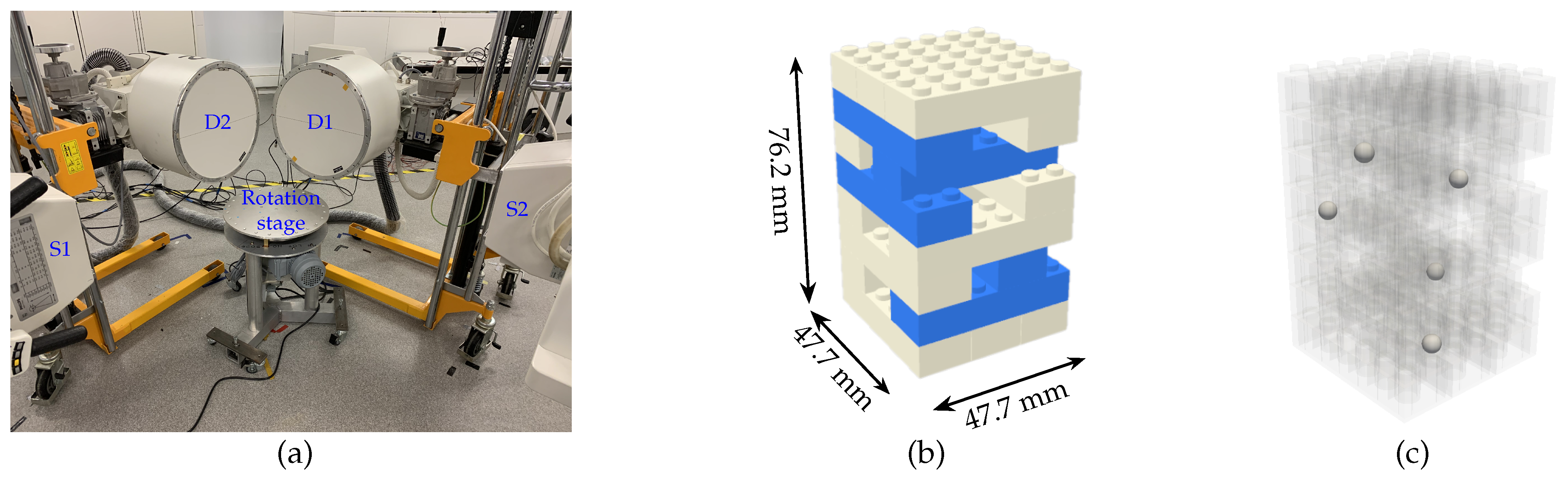
2.1. 3DYMOX System
2.2. LEGO Calibration Phantom
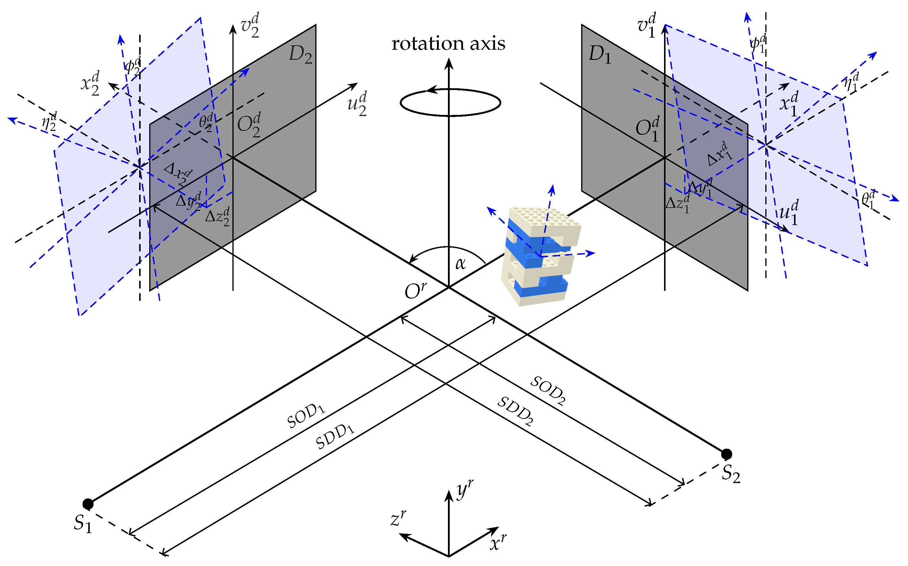
2.3. Stereo Geometry Parameters
2.4. Geometry Calibration
3. Experiments and Results
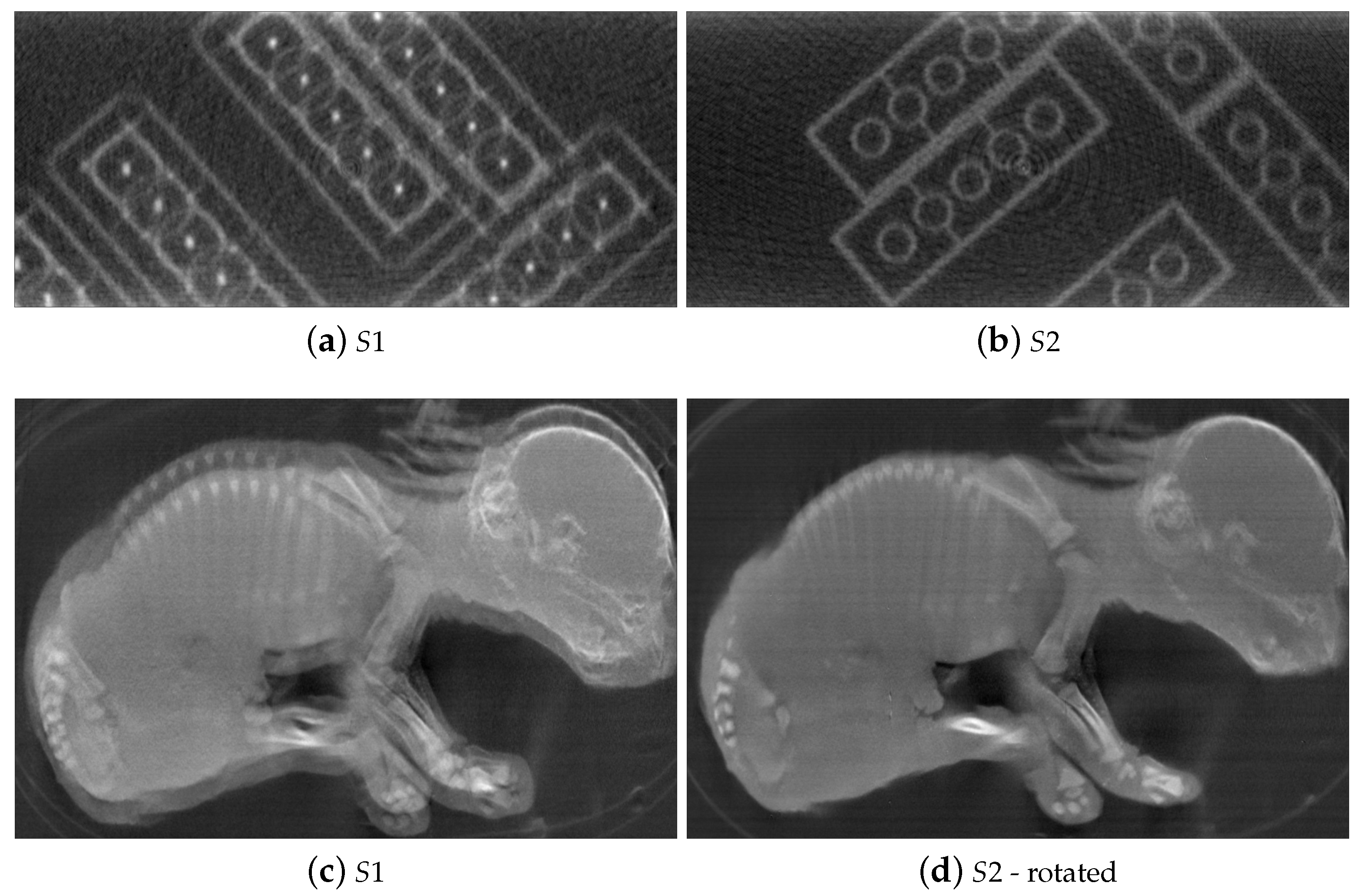
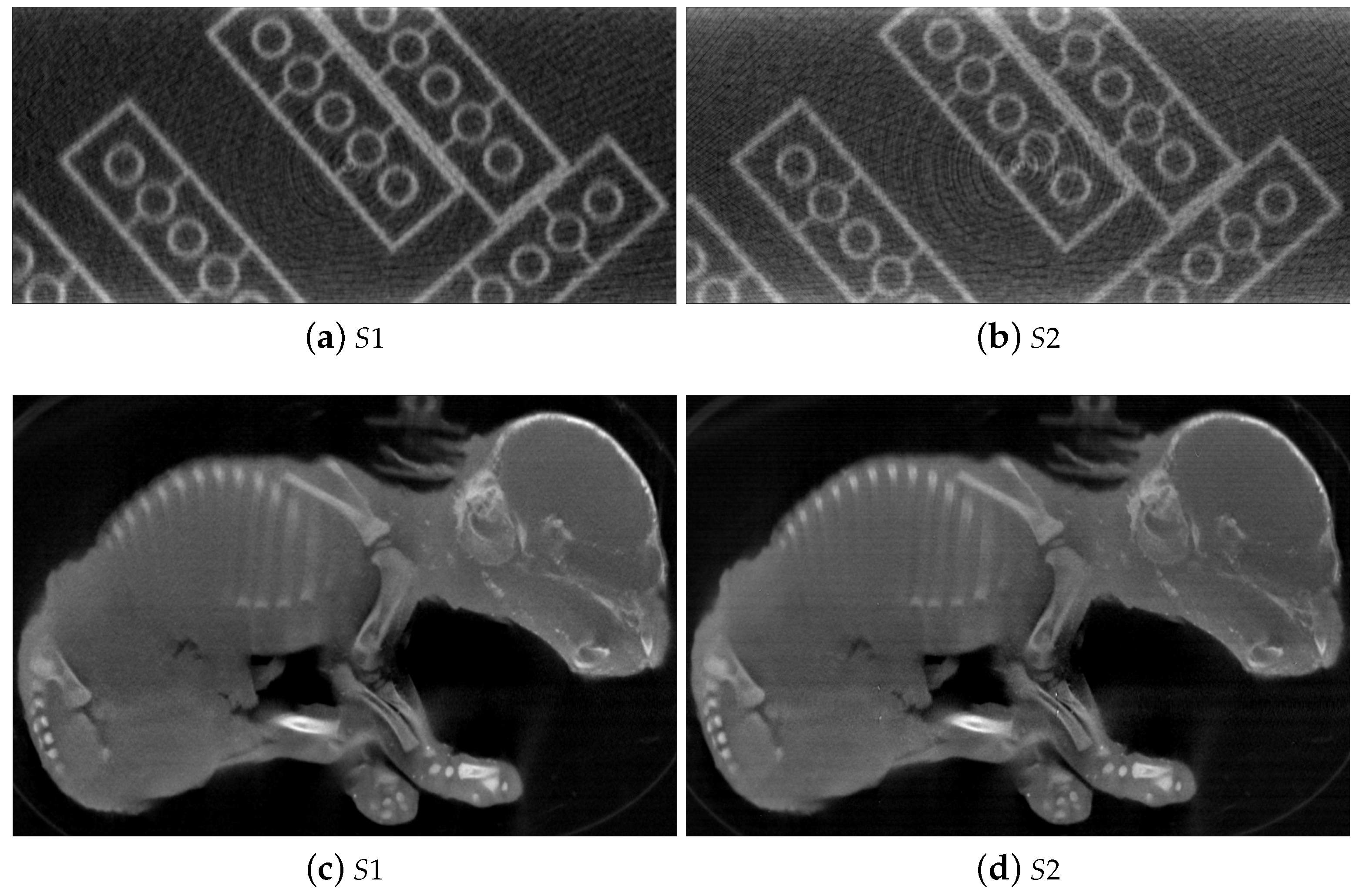
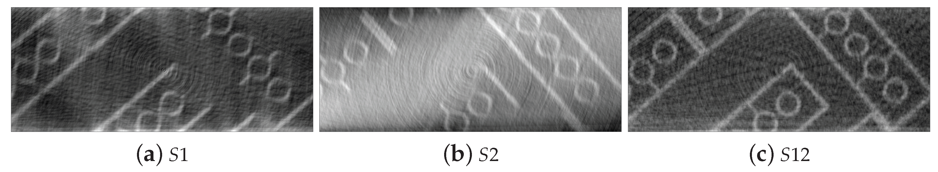
3.1. Experiment with Simulated Data
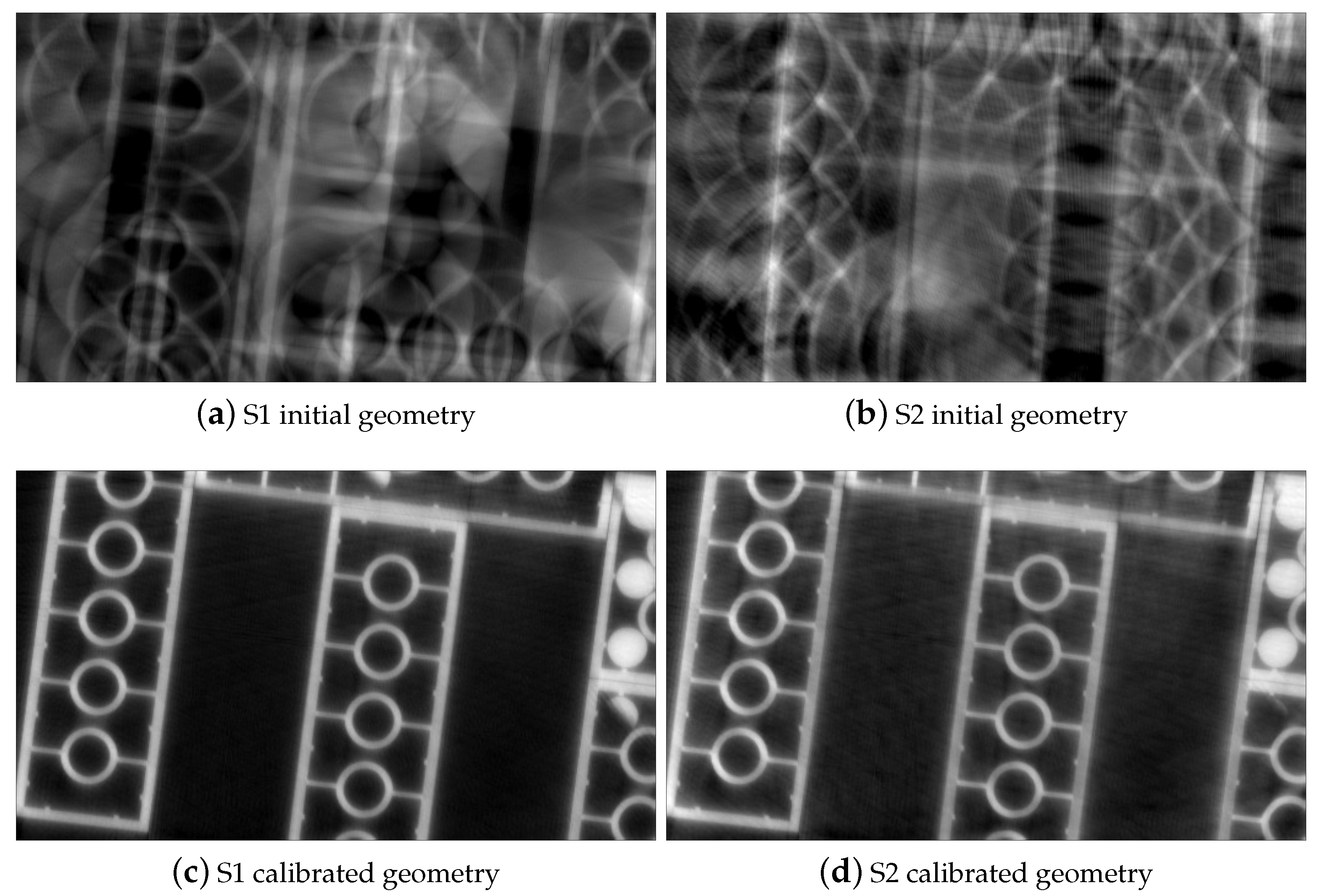
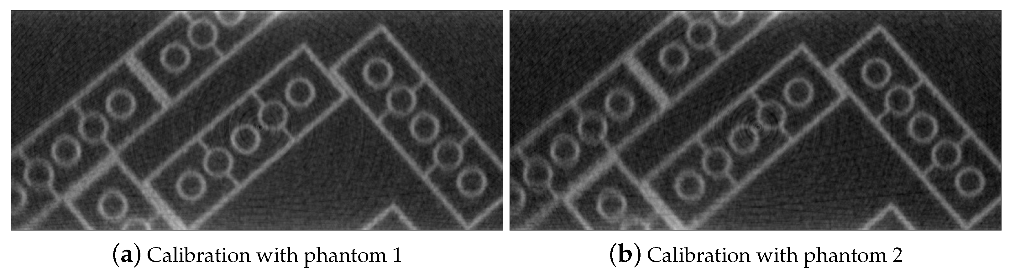
3.2. Experiments with Real Data
4. Discussions and Conclusions
Author Contributions
Funding
Institutional Review Board Statement
Informed Consent Statement
Data Availability Statement
Conflicts of Interest
References
- Kefala, V.; Cyr, A.J.; Harris, M.D.; Hume, D.R.; Davidson, B.S.; Kim, R.H.; Shelburne, K.B. Assessment of Knee Kinematics in Older Adults Using High-Speed Stereo Radiography. Med. Sci. Sport. Exerc. 2017, 49, 2260–2267. [Google Scholar] [CrossRef] [PubMed]
- Kasten, Y.; Doktofsky, D.; Kovler, I. End-To-End Convolutional Neural Network for 3D Reconstruction of Knee Bones from Bi-planar X-Ray Images. In Machine Learning for Medical Image Reconstruction; Springer International Publishing: Berlin/Heidelberg, Germany, 2020; pp. 123–133. [Google Scholar]
- Zollner, B.; Heinz, C.; Pitzler, S.; Manapov, F.; Kantz, S.; Rottler, M.C.; Niyazi, M.; Ganswindt, U.; Belka, C.; Ballhausen, H. Stereoscopic X-ray imaging, cone beam CT, and couch positioning in stereotactic radiotherapy of intracranial tumors: Preliminary results from a cross-modality pilot installation. Radiat. Oncol. 2016, 11, 158. [Google Scholar] [CrossRef] [PubMed] [Green Version]
- Akkoul, S.; Hafiane, A.; Rozenbaum, O.; Lespessailles, E.; Jennane, R. 3D Reconstruction of the proximal femur shape from few pairs of x-ray radiographs. Signal Process. Image Commun. 2017, 59, 65–72. [Google Scholar] [CrossRef] [Green Version]
- Deng, K.; Wei, B.; Chen, M.; Huang, Z.; Wu, H. Realization of real-time X-ray stereoscopic vision during interventional procedures. Sci. Rep. 2018, 8, 15852. [Google Scholar] [CrossRef] [PubMed]
- Sanctorum, J.G.; Adriaens, D.; Dirckx, J.J.J.; Sijbers, J.; Van Ginneken, C.; Aerts, P.; Van Wassenbergh, S. Methods for characterization and optimisation of measuring performance of stereoscopic x-ray systems with image intensifiers. Meas. Sci. Technol. 2019, 30, 105701. [Google Scholar] [CrossRef] [Green Version]
- Parkinson, D.Y.; Knoechelb, C.; Yang, C.; Larabellb, C.A.; Le Gros, M.A. Automatic alignment and reconstruction of images for soft X-ray tomography. J. Struct. Biol. 2012, 177, 259–266. [Google Scholar] [CrossRef] [PubMed] [Green Version]
- Kingston, A.; Sakellariou, A.; Varslot, T.; Myers, G.; Sheppard, A. Reliable automatic alignment of tomographic projection data by passive auto-focus. Med. Phys. 2011, 38, 4934–4945. [Google Scholar] [CrossRef] [PubMed]
- Jun, K.; Yoon, S.; Kwon, K. Alignment Solution for CT Image Reconstruction by Fixed Point and Virtual Rotation Axis. Sci. Rep. 2016, 28. [Google Scholar] [CrossRef] [PubMed]
- Wang, C.C.; Chiang, C.C.; Liang, B.; Yin, G.C.; Weng, Y.T.; Wang, L.C. Fast Projection Matching for X-ray Tomography. Sci. Rep. 2017, 7, 1–11. [Google Scholar] [CrossRef] [PubMed] [Green Version]
- Liu, Y. Improve Industrial Cone-Beam Computed Tomography by Integrating Prior Information. Ph.D. Thesis, ETH Zurich, Zurich, Switzerland, 2017. Available online: https://www.research-collection.ethz.ch/handle/20.500.11850/219410 (accessed on 11 March 2021).
- Cho, Y.; Moseley, D.J.; Siewerdsen, J.H.; Jaffray, D.A. Accurate technique for complete geometric calibration of cone-beam computed tomography systems. Med. Phys. 2005, 32, 968–983. [Google Scholar] [CrossRef] [PubMed]
- Chetley Ford, J.; Zheng, D.; Williamson, J.F. Estimation of CT cone-beam geometry using a novel method insensitive to phantom fabrication inaccuracy: Implications for isocenter localization accuracy. Med. Phys. 2011, 38, 2829–2840. [Google Scholar] [CrossRef] [PubMed] [Green Version]
- Mennessier, C.; Clackdoyle, R.; Noo, F. Direct determination of geometric alignment parameters for cone-beam scanners. Phys. Med. Biol. 2009, 54, 1633. [Google Scholar] [CrossRef] [PubMed] [Green Version]
- Chang, C.H.; Ni, Y.C.; Huang, S.Y.; Hsieh, H.H.; Tseng, S.P.; Tseng, F.P. A geometric calibration method for the digital chest tomosynthesis with dual-axis scanning geometry. PLoS ONE 2019, 14. [Google Scholar] [CrossRef] [PubMed] [Green Version]
- Sawall, S.; Knaup, M.; Kachelrieß, M. A robust geometry estimation method for spiral, sequential and circular cone-beam micro-CT. Med. Phys. 2012, 39, 5384–5392. [Google Scholar] [CrossRef] [PubMed]
- Allab, A.; Vázquez, C.; Cresson, T.; de Guise, J. Calibration of Stereo Radiography System for Radiostereometric Analysis Application. In Proceedings of the 2019 41st Annual International Conference of the IEEE Engineering in Medicine and Biology Society (EMBC), Berlin, Germany, 23–27 July 2019; pp. 4859–4862. [Google Scholar]
- Nguyen, V.; De Beenhouwer, J.; Sanctorum, J.G.; Van Wassenbergh, S.; Bazrafkan, S.; Dirckx, J.J.; Sijbers, J. A low-cost geometry calibration procedure for a modular cone-beam X-ray CT system. Nondestruct. Test. Eval. 2020, 35, 252–265. [Google Scholar] [CrossRef]
- Paudel, K. Stitching of X-ray Images. Master’s Thesis, Uppsala University, Uppsala, Sweden, 2012. Available online: http://uu.diva-portal.org/smash/get/diva2:565399/FULLTEXT01.pdf (accessed on 4 February 2021).
- Group, L. LEGO Group, A Short Presentation. Available online: https://www.lego.com/cdn/cs/aboutus/assets/blt2278c7a21e58e900/LEGOCompanyProfile_2020.pdf (accessed on 11 March 2021).
- 3D2YMOX. 3-Dimensional DYnamic MOrphology Using X-rays. Available online: https://www.uantwerpen.be/en/research-groups/3d2ymox/ (accessed on 11 March 2021).
- Ferrucci, M. Systematic Approach to Geometrical Calibration of X-ray Computed Tomography Instruments. Ph.D. Thesis, KU Leuven, Leuven, Belgium, 2018. Available online: https://lirias.kuleuven.be/retrieve/521553 (accessed on 11 March 2021).
- Theodoridis, S.; Koutroumbas, K. Chapter 8—Template Matching. In Pattern Recognition, 4th ed.; Academic Press: Cambridge, MA, USA, 2009; pp. 481–519. [Google Scholar]
- Nguyen, V.; De Beenhouwer, J.; Bazrafkan, S.; Hoang, A.T.; Van Wassenbergh, S.; Sijbers, J. BeadNet: A network for automated spherical marker detection in radiographs for geometry calibration. In Proceedings of the 6th International Conference on Image Formation in X-Ray Computed Tomography, 6th CTMeeting, Regensburg, Germany, 3–7 August 2020. [Google Scholar]
- He, K.; Zhang, X.; Ren, S.; Sun, J. Deep residual learning for image recognition. In Proceedings of the IEEE Computer Society Conference on Computer Vision and Pattern Recognition, Las Vegas, NV, USA, 26 June–1 July 2016; pp. 770–778. [Google Scholar] [CrossRef] [Green Version]
- Vanderbei, R.J.; Shanno, D.F. An Interior-Point Algorithm for Nonconvex Nonlinear Programming. Comput. Optim. Appl. 1999, 13, 231–252. [Google Scholar] [CrossRef]
- Marinovszki, A.; De Beenhouwer, J.; Sijbers, J. An efficient CAD projector for X-ray projection based 3D inspection with the ASTRA Toolbox. In Proceedings of the 8th Conference on Industrial Computed Tomography, 18th iCT, Wels, Austria, 6–9 February 2018. [Google Scholar]
- Wim, V.A.; Willem, J.P.; Jan, D.B.; Thomas, A.; Sara, B.; Kees, J.B.; Jan, S. The ASTRA Toolbox: A platform for advanced algorithm development in electron tomography. Ultramicroscopy 2015, 157, 35–47. [Google Scholar]
- Wim, v.A.; Willem, J.P.; Jeroen, C.; Eline, J.; Folkert, B.; Andrei, D.; Jan, D.B.; Kees, J.B.; Jan, S. Fast and flexible X-ray tomography using the ASTRA toolbox. Opt. Express 2016, 24, 25129–25147. [Google Scholar]
- Sanctorum, J.G.; Van Wassenbergh, S.; Nguyen, V.; De Beenhouwer, J.; Sijbers, J.; Dirckx, J.J.J. Projection-angle-dependent distortion correction in high-speed image-intensifier-based x-ray computed tomography. Meas. Sci. Technol. 2020, 32, 035404. [Google Scholar] [CrossRef]


| Init. (mm) | 0.00 | 0.00 | 0.00 | 0.00 | 0.00 | 0.00 | 0.00 | 0.00 | 0.00 | 0.00 | 0.00 |
| GT (mm) | −7.96 | 12.6 | −12.6 | 19.7 | −18.5 | −10.1 | 7.21 | −10.2 | −17.8 | 14.0 | 11.9 |
| Err. (m) | 14 | 120 | 2 | 470 | 36 | 2 | 820 | 3600 | 170 | 1 | 8200 |
| Init. () | 0.00 | 0.00 | 0.00 | 90.0 | 0.00 | 0.00 | 0.00 | 0.00 | 0.00 | 0.00 | |
| GT () | 4.08 | 187 | 4.29 | 94.1 | 3.81 | 2.02 | 2.08 | 4.24 | 2.01 | 0.67 | |
| Err. (deg) | 0.004 | 0.015 | 0.010 | 0.008 | 0.006 | 0.031 | 0.021 | 0.007 | 0.098 | 0.070 |
| (mm) | ||||||||||
|---|---|---|---|---|---|---|---|---|---|---|
| Inits. | 0.00 | 0.00 | 0.00 | 0.00 | 0.00 | 0.00 | 0.00 | 0.00 | 0.00 | |
| Phantom 1 | −16.6 | 66.1 | −10.1 | −5.31 | −31.6 | −3.35 | −4.67 | −30.63 | −0.06 | |
| Phantom 2 | 16.7 | 65.4 | −22.3 | −1.85 | −30.8 | −3.61 | −6.08 | −29.6 | −0.05 | |
| (deg) | ||||||||||
| Inits. | 0.00 | 0.00 | 0.00 | 0.00 | 0.00 | 0.00 | 0.00 | 0.00 | 0.00 | 0.00 |
| Phantom 1 | 0.401 | −28.9 | 0.612 | 89.6 | −0.049 | −3.41 | −0.89 | 0.459 | −2.00 | −1.12 |
| Phantom 2 | 0.118 | 42.6 | 0.372 | 89.6 | −0.424 | 2.79 | −4.90 | 0.441 | −1.44 | −1.02 |
Publisher’s Note: MDPI stays neutral with regard to jurisdictional claims in published maps and institutional affiliations. |
© 2021 by the authors. Licensee MDPI, Basel, Switzerland. This article is an open access article distributed under the terms and conditions of the Creative Commons Attribution (CC BY) license (http://creativecommons.org/licenses/by/4.0/).
Share and Cite
Nguyen, V.; Sanctorum, J.G.; Van Wassenbergh, S.; Dirckx, J.J.J.; Sijbers, J.; De Beenhouwer, J. Geometry Calibration of a Modular Stereo Cone-Beam X-ray CT System. J. Imaging 2021, 7, 54. https://0-doi-org.brum.beds.ac.uk/10.3390/jimaging7030054
Nguyen V, Sanctorum JG, Van Wassenbergh S, Dirckx JJJ, Sijbers J, De Beenhouwer J. Geometry Calibration of a Modular Stereo Cone-Beam X-ray CT System. Journal of Imaging. 2021; 7(3):54. https://0-doi-org.brum.beds.ac.uk/10.3390/jimaging7030054
Chicago/Turabian StyleNguyen, Van, Joaquim G. Sanctorum, Sam Van Wassenbergh, Joris J. J. Dirckx, Jan Sijbers, and Jan De Beenhouwer. 2021. "Geometry Calibration of a Modular Stereo Cone-Beam X-ray CT System" Journal of Imaging 7, no. 3: 54. https://0-doi-org.brum.beds.ac.uk/10.3390/jimaging7030054