1. Introduction
Electricity is one of the most important forms of household energy and one of the most important forms of energy for industry and transport (especially electric trains, trams, metro and trolleybuses). With the increasing share of hybrid and electric vehicles, the importance of electricity is also growing in automotive transport. Electricity distribution in households, industry, transport and construction is mostly implemented using electrical cables and, to a lesser extent, by non-insulated electric conductors.
The use of electrical cable gives rise to two significant risks. The first is electric shock. Electric shock has been extensively studied in several scientific papers, e.g., [
1,
2]. To suffer an electric shock from an electrical cable it is necessary that the insulation of the cable is damaged. The insulation may be damaged either mechanically or thermally. The cause of thermal insulation damage is an increase in the ambient temperature, in the area where the electrical cable is installed or through Joule heating (heat released by the electric current through the electrical conductor). Joule heating is calculated from the electrical resistance of the electric conductor and the current flowing through the conductor using the Equation (1), the Joule–Lenz law. A more complex process used to calculate the local volumetric Joule heating is described in the scientific paper [
3]. The influence of the electrical current and the environment on the electrical cable temperature has been studied in detail in scientific papers [
4,
5,
6].
where
P is Joule heating (W),
I is the electrical current through a conductor (A) and
R is the resistance of electrical conductor (Ω).
The second major risk associated with the use of electric cables is fire. Electrical cables can be the ignition source for a fire, the first object ignited during a fire; they can spread a fire and contribute to the fire load in the fire compartment. Electrical cables are sized so that the heat they can dissipate is higher than the Joule heating. Under normal operating conditions, electric cables cannot cause a fire. As a result of an increase of the cable current, a reduction in the cross sectional area of the conductors (mainly due to mechanical damage) or an increase in contact resistance at the point of contact to the electric conductors (electrical cable) at the point of termination (mainly due to surface oxidation, insufficient tightening of the screw in the terminal board or the rheological properties of the electric wires), the Joule heating can rise to a value that exceeds the potential maximum level of heat dissipation from the cable into the surroundings. The result could be a fire caused by the ignition of the cable insulation by the Joule heating. In this case, the electrical cable is directly related to the cause of the fire, i.e., an overload or mechanical damage to the cable. Joule heating has been extensively studied in several scientific papers, [
7,
8,
9]. In addition to Joule heating, which is produced by the electrical cable due to its load current, electrical cables can be ignited by heat from other sources, from a thermal appliance. In this case, the electrical cable is the first item to be ignited, but it is not directly related to the cause of the fire. The issue of the ignition of electrical cables and organic polymers (which are components of electrical cables) by an external heat source has been dealt with by many scientific papers [
10,
11,
12]. In most cases, however, electrical cables are neither the ignition source nor the first object ignited. Nevertheless, the cables significantly affect the development of the fire. In the linear development phase of a fire, the electrical cable can propagate the fire across the surface of the fire compartment and in the fully developed phase of a fire they can spread fire to adjacent fire compartments. Electrical cables further contribute to the total fire load of the fire compartment by the mass and combustion heat of the polymer components in the insulation. Another unfavourable impact of fire on electrical cables is their failure (thermal insulation damage and subsequent short circuit). The result of electrical cable failure is the interruption of supply to powered devices. This impact is most unfavourable, particularly for electrical equipment that must remain in operation for a certain period of time (generally, 30–120 min, e.g., evacuation lifts and escape route emergency lighting). For these applications, special cables are used that can maintain the integrity of the circuit during a fire. The issue of electrical cables and organic polymers (which are components of electric cables) and the heat of combustion and circuit integrity during a fire have been examined in many scientific papers [
13,
14,
15].
All fires involving electrical cables release heat and combustion products into the environment. The heat released has an adverse effect on building structures and, consequently, threatens the lives and health of many people. The heat released during a fire involving electrical cables and organic polymers has been examined in detail in scientific papers [
16,
17,
18]. Combustion products adversely affect the lives and health of people, as well as property (especially works of art and electronics). The main adverse effects of the combustion products are their toxicity and the reduction in visibility. Research into the toxicity of combustion products released during the pyrolysis of electrical cables (and their polymer components) may be found in scientific papers [
19,
20,
21]. Substantially less attention has been paid to the study of the impact of fires in electrical cables on visibility in the area affected by the combustion products. At present, there is a lack of data on the production of smoke from electrical cables. At the same time, there is no methodology available to assess the impact of an electrical cables fire on the reduction in visibility in the area affected by the combustion products.
The visibility significantly influences the orientation of a person during an evacuation and thus also the available safe escape time. In addition, visibility also affects the orientation of fire-fighters and thus their actions during a fire (the search and rescue of people and fighting the fire). Visibility generally depends on the dimensions and optical properties of the observed object. The observed object can either emit or reflect light. The visibility of light-emitting objects increases with increasing brightness. The visibility of light-reflecting objects increases with increasing reflectivity. In general, objects which are illuminated are visible at a greater distance than reflective objects.
Visibility in a smoke-filled area is calculated using the Equation (2) derived by Jin [
22] and detailed in the scientific paper [
23].
where
v is the visibility of signs at the obstruction threshold (m),
k is the smoke extinction coefficient (1/m),
L is the brightness of signs (cd/m
2),
δc is the constant threshold of signs in smoke at the obscuration threshold (-),
σs is the scattering coefficient (1/m) and
E is the mean illuminance of illuminating light from all directions in smoke (lm/m). The “(-)” sign means without unit.
The Technical Standard: IEC 60695-6-1:2005+AMD1:2010 CSV [
24] specifies the Equation (2) in a simplified form (3).
where
γ is the constant of proportionality between the visibility and the smoke extinction coefficient (-).
The Equations (2) and (3) are valid for a visibility distance calculation in the interval from approximately 0.5 to 20 m.
The scientific paper [
22] and the Technical Standard IEC 60695-6-1:2005+AMD1:2010 CSV [
24] recommend a constant of proportionality of
γ = 8 for light-emitting signs and a constant of proportionality of
γ = 3 for light-reflecting signs. The extinction coefficient is calculated according to the Equation (4), which is stated in the technical standard IEC 60695-6-1:2005+AMD1:2010 CSV [
24]. Similar equations are given in scientific papers [
22,
23,
25].
where
S is the smoke extinction area (m
2) and
V is the volume of smoke (m
3).
The smoke extinction area is a basic parameter for each construction product or material which cannot be calculated but is determined by experiment. The smoke extinction area is most often measured using a cone calorimeter. The volume of smoke is given by the sum of the volume of the smoke layer (in the fire compartment) and the volume of smoke exhausted from the fire compartment, according to the Equation (5).
where
VSL is the smoke layer volume (m
3) and
VEO is volume of the smoke exhausted out of the fire compartment (m
3).
The volume of the smoke layer, as well as the amount of smoke exhausted from the fire compartment, depends on many parameters (the rate of heat release, the dimensions of the fire compartment and the dimensions and mutual orientation of the openings in the fire compartment). The detailed procedure for calculating the volume of the smoke layer and the smoke volume exhausted from the fire department is specified in scientific papers [
26,
27,
28].
To assess the impact of electrical cable fires on the reduction in visibility in the affected area, a new approach has been developed in this study. This approach is based on the determination of a critical ratio between the smoke volume (the sum of the smoke volume in the smoke layer and the smoke volume exhausted from the fire compartment) and the length of the burning cable, which predicts a critical value of the reduction in visibility. This ratio reflects how many m
3 of smoke should be exhausted from the fire compartment per meter of burning cable to maintain the required visibility. The length of burning electrical cables is given by the length of cables mounted on the surface in the area or fire compartment. The smoke volume is calculated according to Equation (5). The critical visibility value depends on the size of the area. Verification Method C/VM2:2014 [
29] requires and scientific paper [
30] recommends a visibility of 10 m in smoke filled areas until the evacuation is complete. Exceptions to this are spaces with a surface area of less than 100 m
2, where C/VM2:2014 [
29] allows the visibility to drop to 5 m. However, different visibility limits are reported in selected scientific works. The lowest level of visibility (1.2 m) is recommended by scientific paper [
31]. Recommendations from this reference [
31] are still relevant. There have not been published studies that refute these recommendations. This may be applied in spaces with a small floor area containing a small number of people familiar with the premises (e.g., family houses). In these areas, however, electrical cables do not represent a significant contribution to the fire load and thus do not significantly contribute to a reduction in visibility. Scientific paper [
23] provides more minimum visibility levels. The maximum recommended value is 20 m. This should primarily be applied to very large areas (tunnels, airports, bus and railway stations, metro stations, shopping centres and production halls) where visibility of 20 m is appropriate, not only during evacuation, but also during firefighting (good visibility in the fire-affected area facilitates the activities of the fire brigades). The above-mentioned scientific papers show that in the case of fire engineering, 1.2, 5, 10 and 20 m are considered as the critical visibility values. The minimum visibilities recommended for different premises are illustrated in
Table 1.
The proposed new method for the assessment of the impact of electric cable fire on visibility in a confined space allows for the assessment and comparison of electrical cables in terms of their impact on visibility during a fire. However, the significant benefit of the proposed new method is the fact that the results may be directly used as an input into the calculation of the available safe escape time as well as for the design of smoke and heat control systems or for the design of the openings to exhaust fire products from the fire compartment.
Most European Union member states require (e.g., the Czech Republic and Slovakia) or recommend (e.g., Germany and Spain) that surface mounted electrical cables in public areas with a high fire risk (escape routes, kindergartens, nurseries, metro stations, railway stations, bus stations, road and rail tunnels) should have fire reaction classes B2ca, s1, d1, a1. The purpose of the submitted scientific paper is therefore to assess the impact of a fire involving the selected electrical cables (a cable that retains its circuit integrity during a fire, power cables and signal cables) with fire reaction classes B2ca, s1, d1, a1 on the visibility level in the area based on the determination of the critical ratio of smoke volume to length of burning cable that reduces the visibility of illuminated and reflective signs to 20, 10, 5 and 1.2 m. Plan of the paper is determine of the ratio of smoke volume to length of burning cables with fire reaction classes B2ca, s1, d1, and a1 that cause decrease of visibility below critical values. The plan is also to assess whether there is a significant difference between different cables (with the same B2ca, s1, d1, and a1 reaction to fire class) from the smoke extinction area per cable length point of view.
2. Materials and Methods
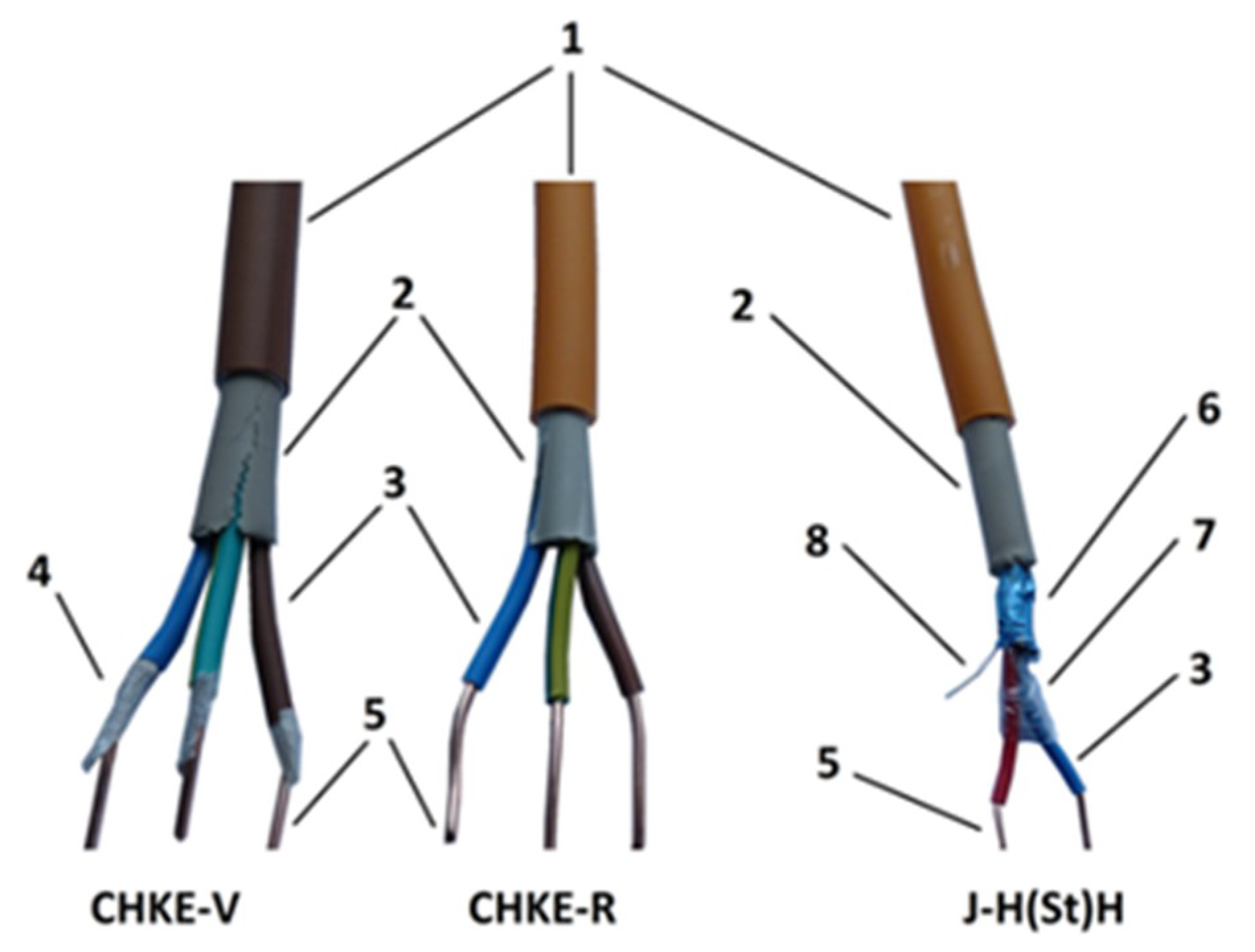
The time dependencies of the critical ratios of smoke volume to burning cable length was determined for three types of cables with fire reaction classes B2
ca, s1, d1, and a1, manufactured and supplied by VUKI, a.s., Slovakia. The electrical cables examined were marked CHKE-V J3x1.5 (hereinafter CHKE-V), CHKE-R J3x1.5 (hereinafter CHKE-R) and J-H(St)H 1 × 2 × 0.8 (hereinafter J-H(St)H). The samples examined are shown in
Figure 1.
The CHKE-V is a fixed power cable that is resistant to flame spread on the surface while maintaining the integrity of the circuit for 60 min during a fire. It is used to supply electrical equipment that must remain functional during a fire (e.g., evacuation lifts) in areas where there is a requirement to limit flame spread over the surface of electric cables (nuclear power stations, rail and road tunnels, airports, bus and railway stations, metro stations, schools and medical facilities). It consists of three copper conductors with a nominal cross-section of 1.5 mm2. Each copper wire is wrapped in a mica-glass tape and insulated using an ethylene-based polymer. The sheath of the cable is an ethylene-based polymer. The bedding between the insulated copper conductors and the cable sheath is an ethylene based polymer filled with metal hydroxides (Al(OH)3 and Mg(OH)2) and chalk. The cable diameter is 9 mm. The nominal voltage rating of the CHKE-V electrical cable is 600 V AC (alternating current) or 1000 V DC (direct current).
The CHKE-R cable is a power cable designed for fixed installations, resistant to flame spread over the surface. It is used to power electrical equipment that is not required to remain functional during a fire (e.g., conventional electrical appliances) in areas where there is a requirement to limit the spread of flame over the surface of electric cables (nuclear power stations, rail and road tunnels, airports, bus and railway stations, metro stations, schools and medical facilities). It consists of three copper conductors with a nominal cross-section of 1.5 mm2 and is isolated using an ethylene-based polymer. The sheath of the electric cable is an ethylene-based polymer. The bedding between the insulated conductors and the cable sheath is an ethylene based polymer filled with metal hydroxides (Al(OH)3 and Mg(OH)2) and chalk. The cable diameter is 8 mm. The nominal voltage rating of the CHKE-R electrical cable is 600 V AC or 1000 V DC.
The J-H(St)H cable is a signal cable for use in fixed installations. It is used to control electrical devices and transmit electrical signals. It consists of two copper conductors with a nominal cross section of 0.5 mm2 and is isolated using an ethylene-based polymer. The insulated conductors are wrapped in an aluminium shielding foil. The sheath of the cable is an ethylene-based polymer. The bedding between the insulated conductors, wrapped in aluminium shielding film and the sheath, is filled with an ethylene based polymer filled with metal hydroxides (Al(OH)3 and Mg(OH)2) and chalk. The cable diameter is 7.2 mm. The nominal voltage rating of J-H(St)H electrical cable is 225 V AC and DC.
The mass of the polymer and metal components per unit length of the electrical cables examined is shown in
Table 2.
The critical ratio of smoke volume to burning cable length was determined for visibilities of v = 20, 10, 5 a 1.2 m for light-emitting signs (γ = 8) and light-reflecting signs (γ = 3). In the first step, the extinction coefficients were calculated from Equation (3) for visibilities of v = 20, 10, 5 a 1.2 m and constants of proportionality γ = 8 and 3. In the second step, smoke volumes were calculated from Equation (4). The extinction coefficients (calculated in step 1) were used in Equation (4) and the smoke extinction areas were measured using a cone calorimeter. The smoke extinction areas used in Equation (4) were calculated per meter for the electrical cables examined, resulting in critical ratios for smoke volume to length of the samples examined, at which the visibility dropped to the defined values (v = 20, 10, 5 and 1.2 m).
Both the cone calorimeter and the test method complied with ISO 5660-1:2015 [
32]. ISO 5660-1:2015 specifies the exact test procedure; the only test conditions that may be modified is the heat flux and the sample orientation. Fire conditions are best simulated using a heat flux of 50 kW/m
2. This is confirmed by the majority of scientific papers, e.g., [
33,
34,
35], that examined organic polymers on a cone calorimeter using a heat flux of 50 kW/m
2, and almost all scientific papers, e.g., [
36,
37,
38], examined the natural and organic polymers using a horizontal orientation. Also, most surface mounted electrical cables in buildings are horizontally oriented. Therefore, in this study, the extinction area of the smoke released per meter of cables was determined at a heat flux of 50 kW/m
2 with a horizontally oriented sample.
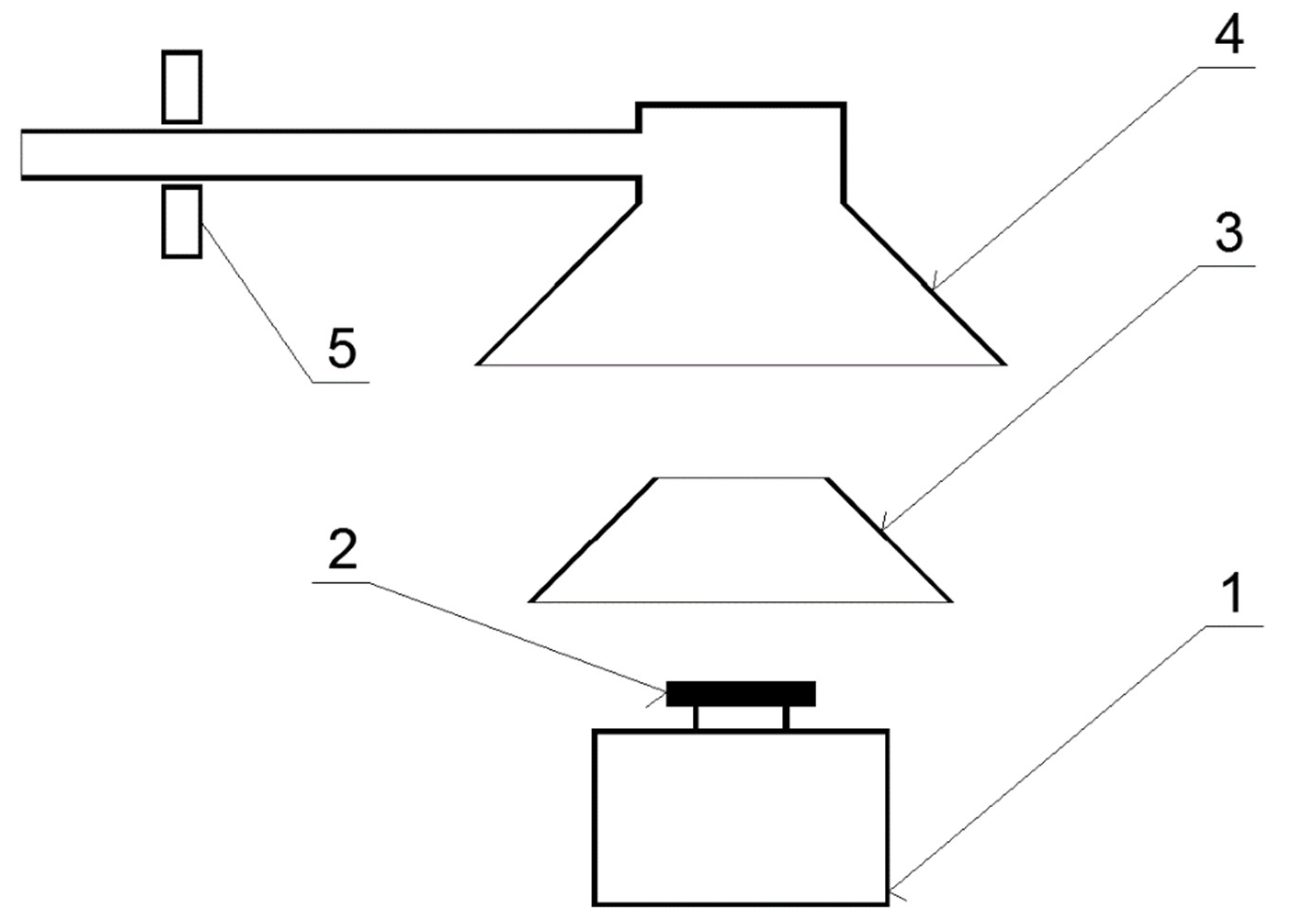
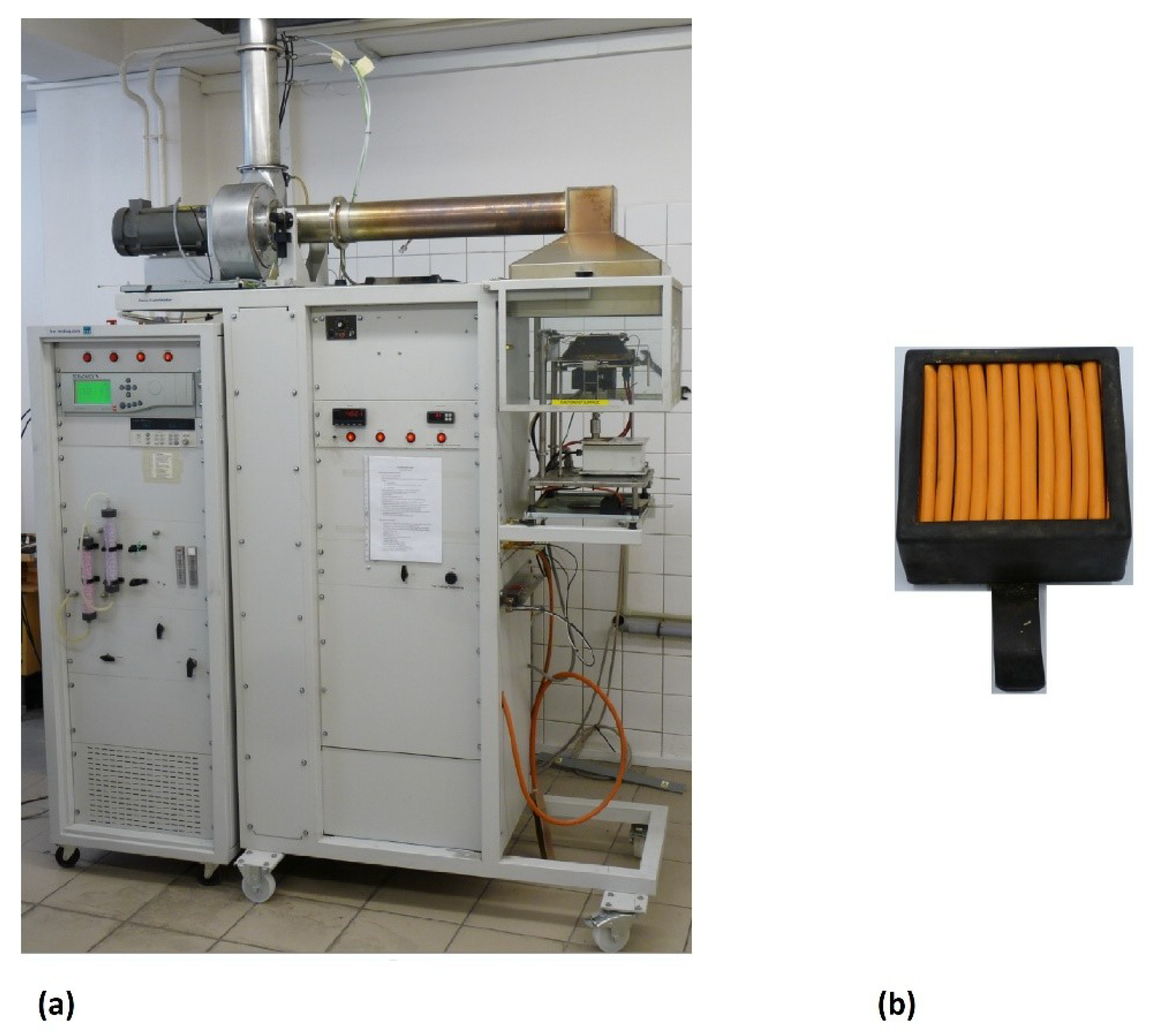
The basic scheme of the cone calorimeter is in
Figure 2. The experiments have been done in the Fire Testing Laboratory of the Slovak University of Technology in Bratislava, Faculty of Materials Science and Technology in Trnava. The cone calorimeter was made and supplied by the Fire Testing Technology, Ltd. (East Grinstead, UK). The photograph of used cone calorimeter and detail photograph of tested cables in the sample holder are illustrated in
Figure 3. Uncertainty of measured values (the extinction area of smoke per sample length) was below 1% (based on uncertainty of the used cone calorimeter components). All details regarding the cone calorimeter and testing procedure are in the ISO 5660-1:2015 [
32] standard.
3. Results and Discussion
The smoke extinction areas determined for the electrical cables examined are shown in
Table 3. The data comparison in
Table 1 and
Table 3 shows that the smoke extinction area is not a linear function of the mass of the polymer components (despite the similar chemical composition), because the CHKE-V cable has a higher mass of polymeric components per meter (
Table 1) and a smaller smoke extinction area (
Table 3) than the CHKE-R cable. This is caused by the influence of the mass ratio of the metal components (copper electric conductors) to the polymeric components on the heat transfer inside the sample (during the exposure of the surface to the external heat flux from the cone emitter). Results from scientific papers [
39,
40,
41] show that the thermal conductivity of the sample (as well as the thermal conductivity of the material under the sample) has a significant effect on the process and products of combustion. Moreover, scientific paper [
41] demonstrates the significant influence of the thermal conductivity of the material under the sample (during cone calorimeter test) on the smoke extinction area of natural and synthetic polymers. With an increase in the mass of polymer components (sheath, insulation and bedding) per meter of the electrical cable, its thermal conductivity decreases. In this respect, the results obtained (
Table 1 and
Table 3) are in line with the results of scientific paper [
41], according to which the smoke extinction area of the smoke from polyethylene and polypropylene increases with increasing thermal conductivity.
Few scientific papers have studied the determination of the extinction area for smoke released from electrical cables, e.g., [
42]. In the cited paper, [
42], the smoke extinction area is determined for 25 different electrical cables using the methods, at that time valid, in IEC 60332-3-24:2000 [
43] and EN 13823:2002 [
44]. The cables examined in the scientific paper, [
42], show smoke extinction areas from 1.5 to almost 1900 m
2. The reason for the differences between the data in
Table 3 and the data published in scientific paper [
42] is the fact that the presented scientific paper examines only non-halogenated electric cables with B2
ca, s1, d1 and a1 fire reaction classes (the cables used in areas with the highest risk to the lives and health of people), while the cited scientific paper, [
42], examines various electrical cables. The second reason is that the smoke extinction areas in
Table 3 are calculated per unit length of cable. The smoke extinction area per unit length provides significantly more information and has greater practical use, while the results in scientific paper [
42] established using methods according to [
43,
44] are practically impossible to calculate back to the unit length of cable. Hence a comparison of the data obtained with that in the cited scientific work is complicated.
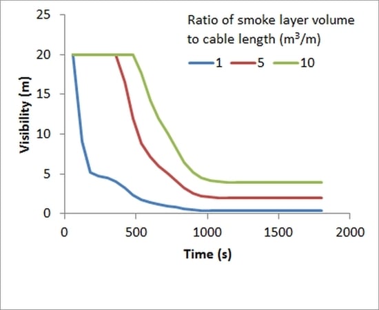
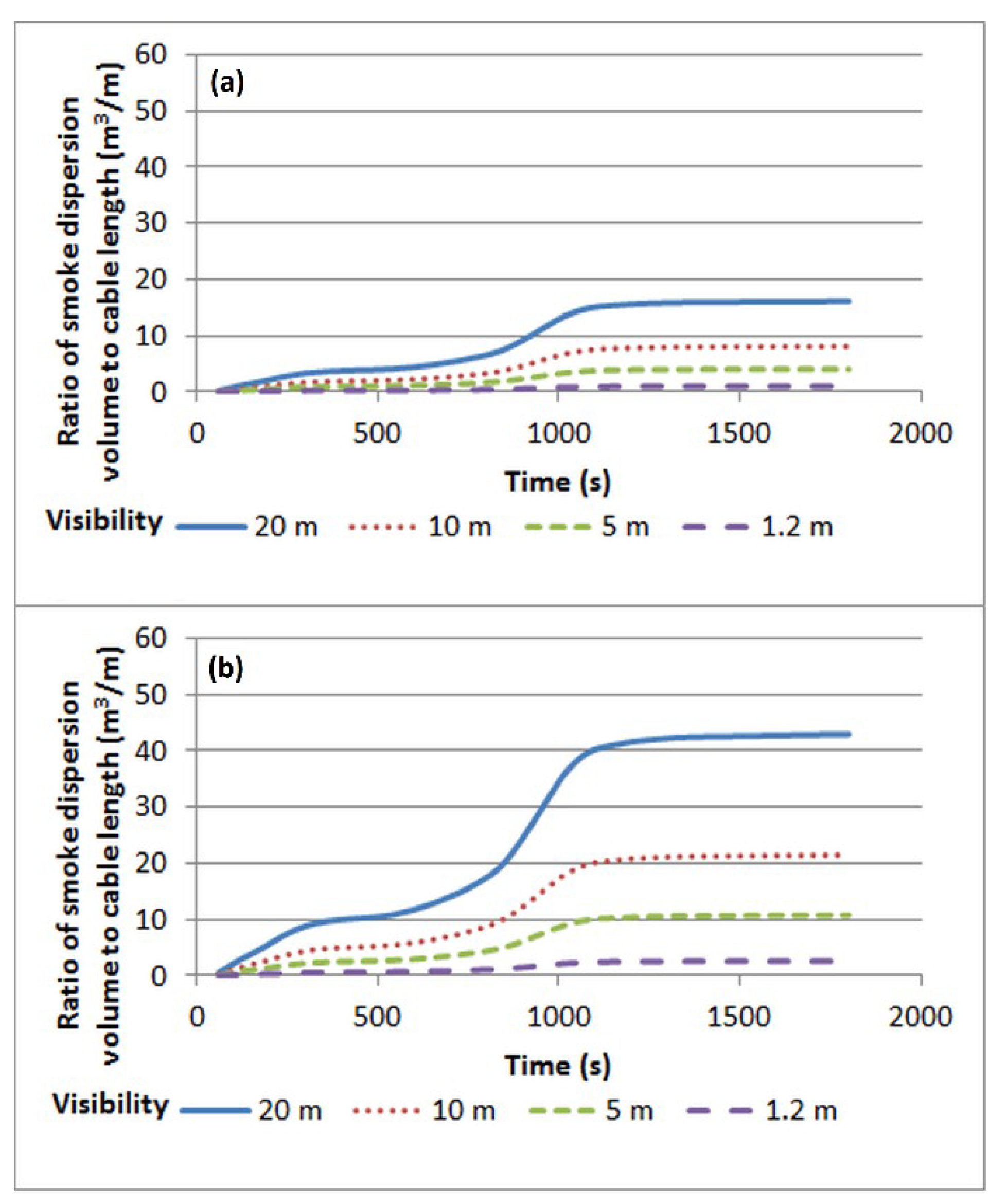
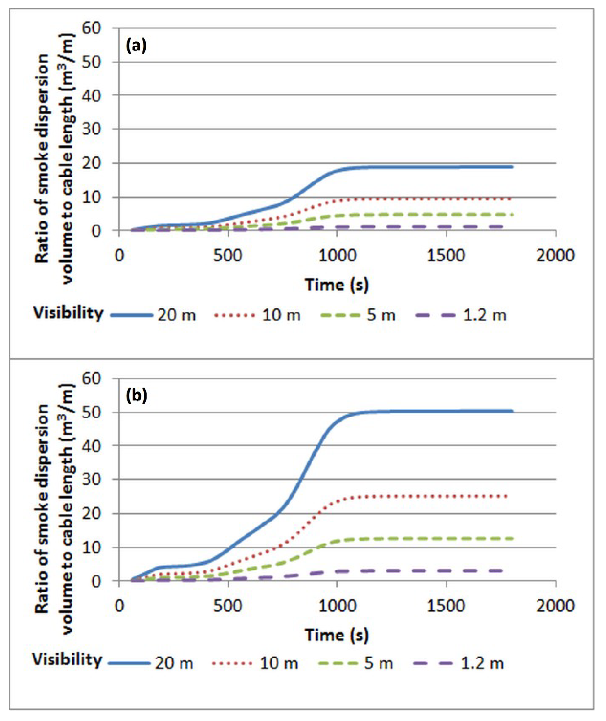
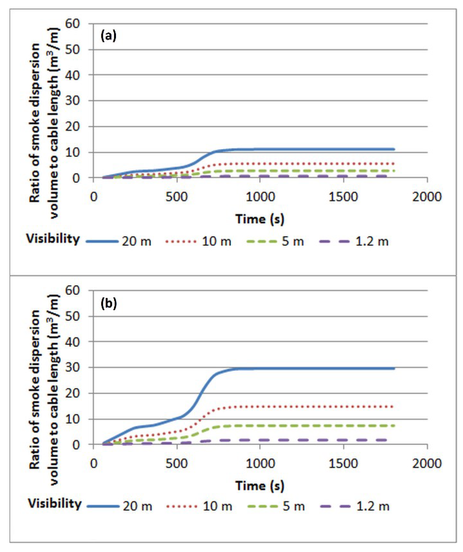
The critical ratios of smoke volume to burning cable length for the reduction of the visibility of light-emitting signs and reflective signs, for values of 20, 10, 5 and 1.2 m are shown in
Figure 4,
Figure 5 and
Figure 6.
The evaluation of the influence of electric cable fire on visibility reduction through the critical ratio of smoke volume to length of burning cable is the original methodology developed in this paper. Therefore, papers with results, with which the data in
Figure 4,
Figure 5 and
Figure 6 could be compared, have not yet been published. The values in
Figure 4,
Figure 5 and
Figure 6 were calculated from the data in
Table 3 and are comparable to the results from scientific paper [
42]. However, the practical interpretation of
Figure 4,
Figure 5 and
Figure 6 is of greatest importance. The critical ratio of smoke volume to length of cable (at a specific time interval) represents the minimum volume, into which the smoke released from one meter of cable must be dispersed (the sum of the volume of the smoke layer and the volume of smoke exhausted from the fire compartment through windows, doors and artificial ventilation) to maintain the required visibility. In the practical design for the fire safety of buildings, it is sufficient to know the length of surface mounted electrical cables in the area, the required minimum visibility (most often at least 10 m), and the values in
Figure 4,
Figure 5 and
Figure 6 allow a simple calculation of the smallest amount of smoke that must be exhausted from the fire compartment to maintain the required visibility.
In
Figure 4,
Figure 5 and
Figure 6, approximately over the time interval of 600 to 1000 s (
Figure 4), from 600 to 1000 s (
Figure 5) and from 500 to 700 s (
Figure 6), there is a very rapid increase in the critical ratio of smoke volume to length of the burning cable. The cause of this rapid increase is that the outer sheath is burnt through and the subsequent burning (thermal decomposition) of the filling and insulation of the electrical conductors.
Figure 4,
Figure 5 and
Figure 6 also show that after approximately 700 s (
Figure 6), 1000 s (
Figure 5) and 1200 s (
Figure 4), the critical ratio of smoke volume to burning cable length is practically constant. This is caused by the practically complete burnout of the polymer components of the cables (virtually no additional smoke is released).
In most areas the Verification Method C/VM2:2014 [
29] requires a visibility of 10 m during a fire until the evacuation is completed. The maximum allowed evacuation time in most areas does not exceed 10 min.
Figure 4,
Figure 5 and
Figure 6 show that, in order to meet these requirements for reflective signs, it is necessary to ensure the removal of approximately 6 m
3 of smoke (CHKE-V), 7 m
3 (CHKE-R) 7.5 m
3 (J-H (St) H) from the fire compartment per meter of cable length. To ensure the required visibility of light-emitting signs, it is necessary to ensure the removal of approximately 2.2 m
3 of smoke (CHKE-V), 2.6 m
3 (CHKE-R) 2.8 m
3 (J-H(St)H) from the area per meter of cable. Since the differences among the examined electric cables are relatively small, it is possible to conclude from the obtained data that in order to maintain visibility of reflective signs, for a fire with halogen-free cables with diameters in the range of 7–10 mm and a fire class of B2
ca, s1, d1, a1, it is necessary to ensure total smoke removal (in the time interval from 0 to 600 s) of at least 7.5 m
3 per meter of cable length. To ensure that light-emitting signs are visible at 10 m during a fire with the same electric cables, over the same time interval, it is necessary to ensure smoke removal from the fire compartment of at least 2.8 m
3 per meter of cable. However, in smoke and heat control systems design, the nonlinear nature of the time dependence of the critical ratio of smoke volume to the length of burning cable must be considered (
Figure 4,
Figure 5 and
Figure 6).
In addition to evacuation, visibility is also an important factor in extinguishing the fire. The duration of fire extinguishing operations is normally 30 min.
Figure 4,
Figure 5 and
Figure 6 show that in order to maintain visibility of reflective signs, it is necessary to provide smoke removal from the area of approximately 21.5 m
3 (CHKE-V), 25 m
3 (CHKE-R) or 15 m
3 (J-H(St)H) per meter of cable. In order to maintain the stated visibility with light-emitting signs, it is necessary to provide smoke removal from the area of approximately 8 m
3 (CHKE-V), 9.5 m
3 (CHKE-R) or 5.5 m
3 (J-H(St)H) per meter of cable. At the 30-min interval, therefore, the difference between the power cables (CHKE-V and CHKE-R) and the signal cable (J-H(st)H) is quite pronounced. This is probably due to the lower mass of polymer components per unit length in the J-H(St)H signal cable compared to the CHKE-V and CHKE-R power cables (
Table 1).
For practical application of data in
Figure 4,
Figure 5 and
Figure 6 it is needed to know the flame spread rate over cables surface. However, investigated cables have been classified as B2
ca. Cables with this classification virtually not spread flame during pre-flashover phase (they only burn on their surface that is directly exposed to the fire—it is one of the condition for classification to this class). Another case is a flashover. After flashover the cables start burning over their entire surface immediately. Second possible scenario is ignition by the Joule heating (overhead). Entire surface of overloaded electrical cable will start burning immediately in this case.
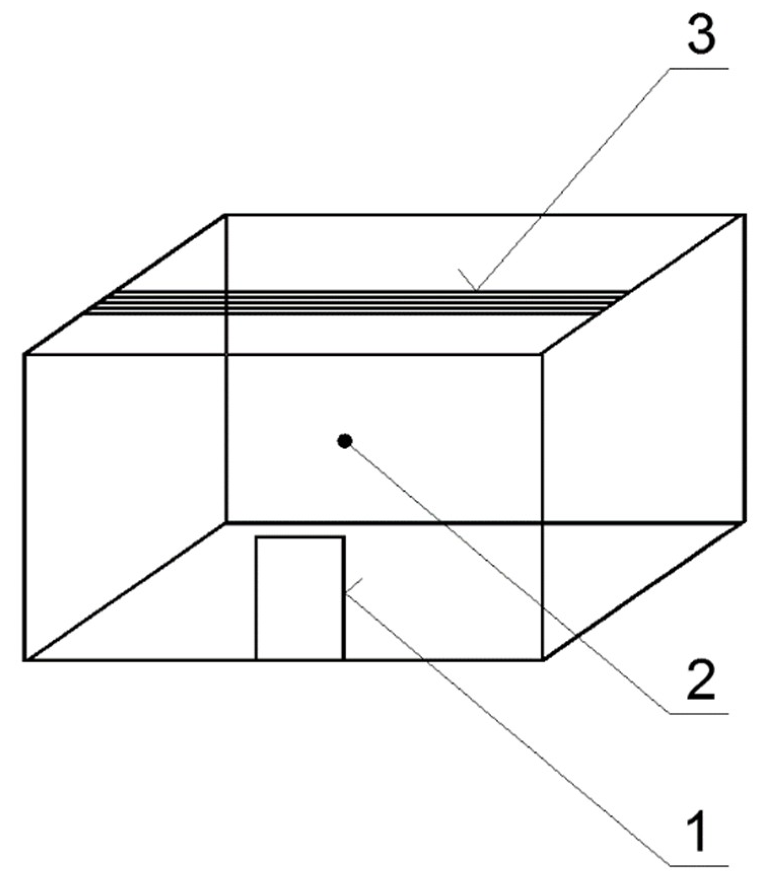
Application to Selected Fire Scenario
Obtained data are applied to selected fire scenario. In this scenario five investigated cables (one next to another) are installed under ceiling of production hall. The dimension of production hall is 20 × 10 × 8 m. Windows and doors are closed. The production hall is in
Figure 7. All cables are ignited by Joule heating (overload). Total length of cables is 5 × 20 = 100 m.
The smoke layer height (measured from smoke layer border and ceiling) was calculated according to Equation (6) [
26].
where
zH is the smoke layer height measured from smoke layer border to ceiling (m),
H is the fire compartment height (m),
α is the fire growth coefficient (kW/s
2)—for this scenario it is 0.003 kW/s
2,
A is the fire compartment area (m
2),
n is coefficient of fire type (-)—for t-quadratic fire it is 2 and
t is time after time ignition (s).
Equation (6) proves that smoke volume is not a material parameter, but is determined by geometry of the fire compartment. Material parameter is extinction area of smoke.
From smoke layer height the smoke volume (as product of smoke layer height and fire compartment area) was calculated. The results are in
Table 4. From data in
Table 4 and in
Figure 4,
Figure 5 and
Figure 6 or from data in
Table 3 was calculated smoke extinction coefficient according to Equation (4). Values of the smoke extinction coefficient are in
Table 5. Visibilities during selected fire scenario are in
Table 6.
Data in
Table 6 prove that between electrical cables classified to the same fire class (B2
ca, s1, d1, and a1) are significant differences from visibility, during the same fire scenario, point of view. Therefore, only fire class of the electrical cable should not be sufficient for comprehensive fire risk assessment of the electrical cable. The exact value of the smoke extinction area of the electrical cable should be taken into consideration for this purpose.

 ,
, 


