
Retrofitting Agricultural Self-Propelled Machines with Roll-Over and Tip-Over Protective Structures


1
Italian Workers’ Compensation Authority (INAIL) Via Fontana Candida, 1, Monte Porzio Catone, 00078 Rome, Italy
2
Department of Agricultural and Environmental Sciences—Production, Territory, Agroenergy, University of Milan, 20133 Milan, Italy
*
Author to whom correspondence should be addressed.
Safety 2021, 7(2), 46; https://0-doi-org.brum.beds.ac.uk/10.3390/safety7020046
Submission received: 30 March 2021
/
Revised: 24 May 2021
/
Accepted: 2 June 2021
/
Published: 4 June 2021
Abstract
:In the agricultural sector, the loss of stability related to the use of self-propelled agricultural machinery (SPAM) has caused and continues to cause accidents, often with fatal outcomes. The probability of occurrence of this risk can be reduced by acting on various aspects, but above all the presence of a protective structure is necessary. Depending on the machine, the protective structure can be a roll-over protective structure (ROPS), or a tip-over protective structure (TOPS). Hence, to reduce this gap, a reverse engineering approach and virtual engineering methods were applied starting from the analysis of harmonized standards actually in force, with the goal of providing both a reference procedure to be used in the risk assessment analysis of SPAM’s protective structures and technical information to manufacture and install protective structure on old agricultural machinery. Two representative case studies were used to validate the procedure by means of finite element method (FEM) analyses and computer aided design (CAD) prototyping. Results show that the proposed approach can represent a useful indication for the safety update of this type of machinery.
1. Introduction
Recent developments of safety legislation in the agriculture and forestry sector have brought to light the growing awareness of occupational health and safety (OHS) from both the equipment manufacturers’ and users’ standpoints. However, there are still difficulties affecting the implementation of safety measures among farmers at a practical level, as reported by numerous studies, which indicated agriculture as a very hazardous sector [1,2,3]. This aspect is confirmed by accident statistics that show a high rate of fatal and non-fatal accidents of farmers worldwide [4,5,6,7,8].
In particular, in Italy, considering serious accidents, the accident statistics indicate that the frequency index (i.e., number of injured workers per 1000 employees) related to agricultural activities is much higher than the one related to the industrial sector [9]. Moreover, analyzing accident reports more in detail, it emerges that the most dangerous activities (considering both the number of permanent injuries and fatalities) are the ones involving the use of machinery and work equipment [10,11,12,13,14].
The main reasons for such a situation can be ascribed to the following aspects: the obsolescence of a large amount of machinery, which need to be adapted to the latest safety requirements; the lack of knowledge of safety rules when using work equipment, most of which requires specific training and/or a qualification; and the lack of adequate information on the safety procedures aimed at maintaining or updating agricultural machinery and equipment, as pointed out by numerous studies [7,8,9,10,11,12,13,14,15,16,17,18].
To reduce such a phenomenon, the National Institute for Insurance against Accidents at Work (INAIL), in collaboration with academia and research institutes, has developed numerous initiatives aimed at supporting agricultural machinery manufacturers, suppliers, workshops, and users in dealing with the update of the equipment to the latest safety requirements. In this ambit, INAL has issued guidelines on the retrofitting of roll-over protective structures (ROPS) for agricultural and forestry tractors [19].
Actually, this open-source database is constantly updated and both constructive and installation characteristics of different types of ROPS for the most diffused tractors in Italy are available. Nowadays, the presence of these safety components (i.e., ROPS and seatbelt) is mandatory in most countries, both for new tractors and for the older ones, which shall be retrofitted accordingly.
The same requirements apply to self-propelled agricultural machinery (SPAM), such as harvesters, but in this context, there is a lack of information on how these safety components should be manufactured and installed correctly. As a matter of fact, it should be noted that, on the one hand, the ISO 16231-1-2 [20,21] standards provide safety requisites for the assessment of the stability of SPAM, indicating namely:
- Part 1 (principles), the criteria for risk assessment to determine the roll-over hazard and the protective measures to reduce the risk of roll-over considering the machine self-protective structure (SPS) (i.e., a part of the machinery that contributes operator protection absorbing roll-over energy and loads) as well as the roll-over protective structures (ROPS) and tip-over protective structures (TOPS) solutions.
- Part 2 (determination of static stability and test procedures), the methodology to calculate SPAM stability via the static overturning angle (SOA).
On the other hand, these harmonized standards do not provide test criteria for SPS and/or ROPS/TOPS to be installed on the machinery. An attempt to solve this problem was made at the international level by a specific working group of the Organization for Economic Cooperation and Development (OECD), which suggested to adapt the criteria used for testing tractors’ protective structures [22] to SPAM [23,24]. Accordingly, they also harmonized standards for machinery safety to be used as a reference [25,26].
However, no technical information has been provided so far on how to implement these solutions: in particular, the main criticality relies on the definition and evaluation of the machinery hard parts on which ROPS/TOPS structures can be designed and installed. Based on this, INAIL promoted a specific research activity aimed at reducing such a gap, and the present study presents the first results of this project, which focused on the definition of the technical issues to be faced in loss of stability risk assessment and ROPS/TOPS design for SPAM. More in detail, following a reverse engineering approach, the study aimed at the definition of a methodology for the proper development of protective structures for SPAMs. The core of this approach relies on virtual prototyping by means of computer aided engineering (CAE) tools, which allows for the development of ROPS/TOPS solutions and the verification of their protection capacity considering the machines’ features. Two representative case studies are illustrated to better elucidate the proposed methodology and its practical implications.
Therefore, this approach can augment knowledge in the risk assessment analysis of SPAM’s protective structures, providing practical references for their development.
The remainder of the article is structured in the following way: In the next section, the technical features of this type of machinery are illustrated. Then, in Section 3, the research methodology is described, while Section 4 shows its application to different case studies. Section 5 concludes the paper discussing main results and illustrating future actions to be carried out.
2. Safety Problems of Self-Propelled Machinery
The SPAM category includes a wide group of machinery, ranging from harvesters to sprayers, combine harvesters, and so on. The main characteristics of this type of work equipment rely on the fact that:
- The driving of the machine is a ride-on operator type;
- The frame of the machine does not have the tractor structural configuration;
- The unladen mass is not less the 400 kg.
For this type of machinery, the unladen mass is referred to the mass of the machine excluding optional accessories, but including coolant, oils, fuel, and tools (when also installed, the protective structure weight is included in the unladen mass); conversely, the laden mass includes tyre ballast, mounted implements, mounted equipment, any specialized components, etc.
Hence, the most critical feature related to the use of these machines is represented by the loss of stability when working in the field. The main factors influencing both the machinery stability and the operator protection in case of stability loss can be summarized as follows:
- The mass of the machine with closed full tanks, which can increase about 40–45% of the unladen mass;
- Several SPAM types (especially harvesters used in vineyards) are equipped with a manual or automatic self-leveling system that can improve the machine stability until to a 30% lateral slope;
- The distribution of the unladen/laden mass of the machine axes largely impacts the overturning occurrence.
Recent reports concerning the occurrence of occupational accidents in the sector of agriculture in Italy show that the number of permanent injuries/fatalities is quite large, and the most dangerous activities are the ones involving the use of machinery and mechanical equipment [17]. In particular, focusing on SPAMs, a research activity [27] investigating the use of this type of equipment highlights that the risk of roll-over in the case of harvesters and self-propelled sprayers is relevant as they are mainly used on slopes with a gradient ranging from 20° to 35° degrees. Similarly, Mayrhofer and colleagues [28] underlined the increased number of roll-overs involving combine harvesters, grape harvesters, and sprayers. These events represent 7% of total accidents occurring yearly, as reported by the INAIL Observatory on serious and fatal accidents in agriculture, which was recently set up to complement the collection of fatal accidents involving agricultural machinery [29]. Such issues are also confirmed by the analysis of a specific sub-working group (SWG) issued by the OECD [27], who reported that for the grape harvesters, the most predictable accident is the side roll-over (tip-over), taking into account that the event could be probably conclude in a side/front or in a side/rear overturning. In Figure 1, examples of recent SPAM’s accidents investigated by INAIL are reported, showing a roll-over (Figure 1a) and tip over (Figure 1b), respectively: they represent the most common accident types involving SPAMs.
Therefore, focusing on these types of occurrences from the machine behavior point of view the following assumptions can be made. On the one hand, the SPAM could be assimilated to earth-moving machinery with respect to the roll-over behavior. On the other hand, for SPAMs such as self-propelled sprayers different situations depending on their shape, and in some cases on their silhouette, should be considered, which leads to also considering the overturning behavior similar to that of agricultural tractors. In addition, it has to be noted that, while the occurrence of this type of accident can be related to different factors, such as human errors in evaluating the gradient of the slope, in maneuvering the machine, or in an improper mass balance [26,30], the lack of a proper protective structure is the cause of most serious injuries and fatalities [23].
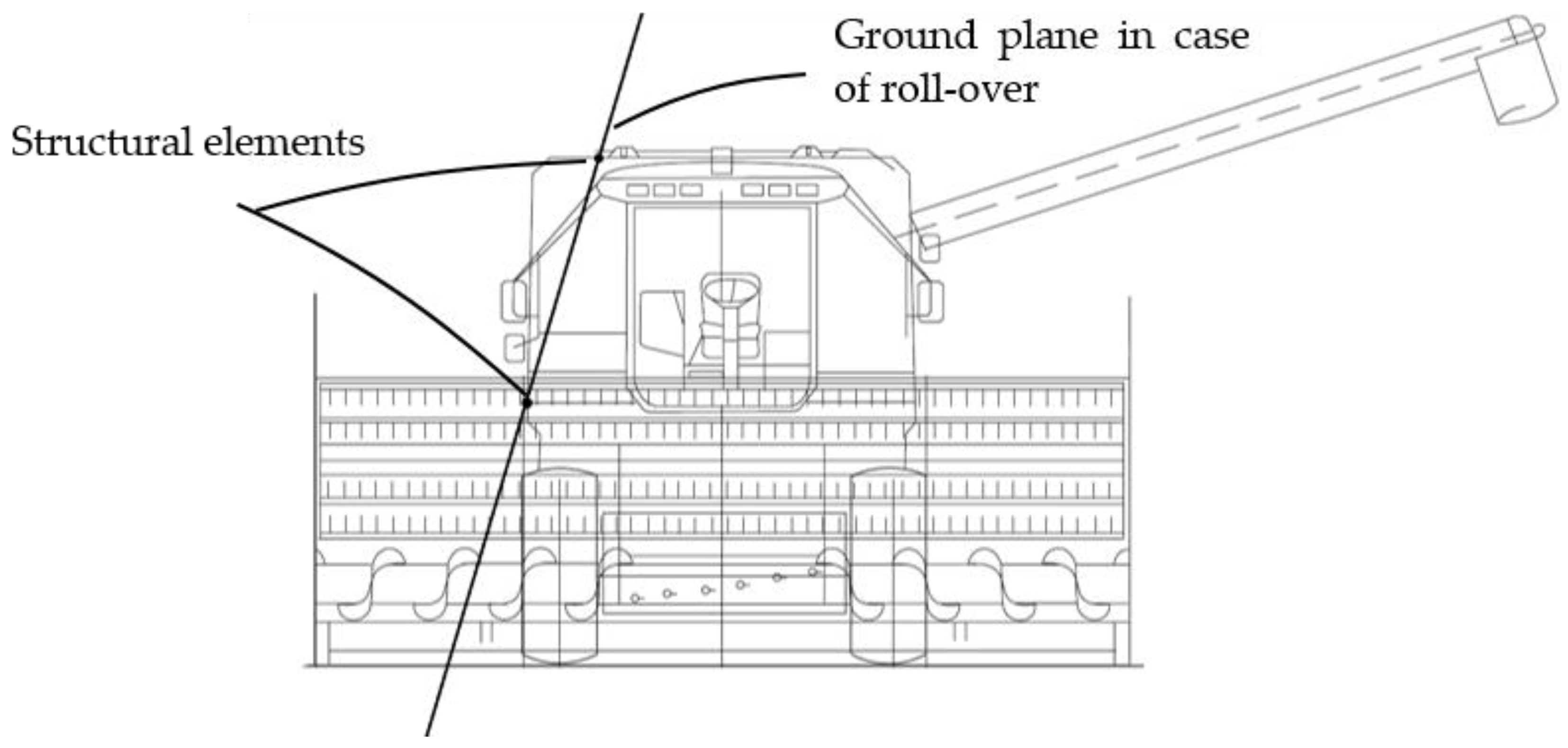
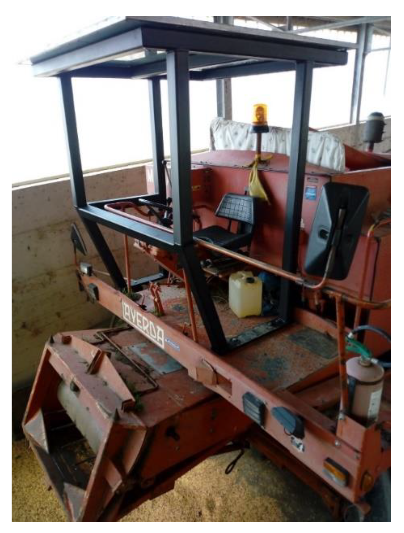
However, even though some types of SPAM already present structural elements that could reduce the risks for the operator in case of roll-over (for example, in Figure 2, structural elements of a combine harvester are shown, which could protect the operator’s position or, at least, contribute to reduce the amount of energy to be absorbed by an eventual ROPS/TOPS structure), no specific procedures addressing manufacturers on how to ensure the effectiveness of SPAMs’ protective structures are available at a normative level [23] nor at the technical level [28].
3. Materials and Methods
Based on the above considerations, a loss of stability risk reduction is adopted to develop a methodology for designing and proving ROPS/TOPS devices for SPAMs, which can be recognized as a technical reference for manufacturers. In particular, such a methodology is useful for situations similar to that of retrofitting, where the experimental tests cannot be carried out, and only virtual engineering tools can help in the loss of stability risk assessment analysis to model effective protective structures. The use of modeling and virtual testing is largely used, especially for the development of protective structures destined to retrofit already-in-use machinery, not only in the agricultural sector [29], but also in other fields such as construction and mining [31,32] The methodology consists of the following main phases, whose tools and methods are summarized in Table 1:
- Detection of the machinery features;
- Loss of stability risk assessment;
- Protective structure design;
- Protective structure building and functional testing.
The core of the methodology is the reverse engineering (RE) approach, which can be described as the process that results in the development of mathematical models from a physical one, to use the words of Afeez et al. [33]. Such a process, whose key elements are represented by CAE/CAD tools, are largely used for the design and testing of products/elements that do not exist or in the case of retrofitting/updating existing products of large dimensions.
More in detail, the above methodology can be illustrated by means of a decision-making flow chart (Figure 3), representing the different tools, activities, and verifications involved in the proposed ROPS/TOPS design and development approach, starting from the identification of the machinery features up to the evaluation of the ROPS/TOPS validity.
3.1. Detection of the Machinery Features
The first step of the analysis is about the knowledge of the machine physical characteristics: due to the variety of SPAMs, this is an important issue as it allows for deciding if it is necessary to adopt a protective structure and what are the test and acceptance criteria to be applied. In such a context, not only is technical information on the physical characteristics of the machinery required (e.g., the definition of the most suitable fitting points), but also data concerning the type of accidents that occurred and information on the real usage of the machinery.
Moreover, the SWG [27] defined the guidelines for testing ROPS fitted on SPAM. According to that, the first step concerns the technical data detection to determine the machine performances related to the loss of stability. They play an important role in the loss of stability risk assessment and consequently on the testing criteria. For that goal, the following parameters are relevant:
- Number of axles;
- Track;
- Wheelbase;
- Overall width;
- Adjustable height;
- Longitudinal position of the cab versus the center of gravity;
- Hard points as a component of the protective system;
- The machine is fitted with closed or open tanks;
- Maximum speed (range 0–16 km/h);
- Square contour of the SPAM (i.e., the wheelbase is roughly equivalent to the track width);
- Maximum operating slope (evaluation or estimation).
3.2. Loss of Stability Risk Assessment
Using the data of the first step, the type of roll-over for the examined SPAM must be defined. There are three options:
- No loss of stability;
- Full roll-over;
- Tip-over.
As mentioned before, the ISO standard 16231 gives the opportunity to calculate the stability overturning angle and to compare it with minimum stability angles. In order to improve safety and further and effectively reduce the risk for the operator, in the case of agricultural machinery, at least the tip-over must be considered. The roll-over type determination leads to predicting the requirements in terms of forces to be applied and energies to be absorbed to the protective structure. In this way, the acceptance criteria concern the protective structure’s ability to protect the survival zone, which can be referenced as deflection limiting volume (EN ISO 3164 and OECD Code 8) or clearance zone (CZ) (OECD Codes 3, 4, 7 and 9).
3.3. Protective Structure Design
This phase consists in the virtual prototyping of the protective structure and has sub-phases, the first one is about the reverse engineering of the SPAM chassis and the components of the machine that can interfere with the protective structure. By means of the CAD software, the simplified virtual model of the machine is virtually replicated, in particular, parts of the chassis that are designated to support the ROPS/TOPS structure mountings. The following phase concerns the virtual prototyping of the protective structure. There are no predefined rules in this sub-phase, the designer’s experience has the major impact on the final result. As matter of fact, unlike tractors, in SPAM retrofitting, there are no structural chassis elements, and the operator seat position is common to all typologies. While for agricultural tractors the operator’s seat is normally in the median longitudinal plane and between the front and rear axles, SPAM can have the operator’s seat in the forward position and/or located on one side of the machine frame. Moreover, the typical tractor ROPS is made of mountings and a top structure, which is a two- or four-post structural frame. On average, the mounting overall height is about 1 m, while the top structure has a height of less than 1.4 m from the operator’s seat. Furthermore, the mountings can be easily fixed on the tractor axles and/or gearbox or machine body, which are feasible and very strong supports. Usually, such conditions are not encountered in SPAM due to the lack of general hard fixture points on which the ROPS/TOPS can be installed and/or due to the relevant height of the mountings that are required to reach the driver’s place. The last sub-phases are that of the structural validation of the ROPS/TOPS structure by means of the finite element method and subsequent analysis ([34]), applying the sequence of tests provided by the standard of phase 2. In this sub-phase, the designer evaluates the deflection-limiting volume as intrusion/unprotecting in a suitable way ([35]), simulating the elastic and plastic behavior of the steel material. If the structural validation fails, the virtual prototyping restarts from the protective structure virtual model, which updates iteratively.
3.4. Protective Structure Building and Functional Testing
Once the structural validation of the protective structure is carried out, the physical structure can be built and installed. This final test has the objective to verify the practical suitability of the structure to the characteristics of the machinery, avoiding interference with other machine elements and the introduction of additional risks during normal use.
4. Case Studies
The proposed procedure was applied to two different case studies concerning a forage harvester and a combine harvester, respectively, since these machines can be considered as cases representative of ROPS design in the SPAM group. Actually, the former had a chassis very similar to that of tractor carriers, with an advanced position of the driver’s seat. This is a common situation among SPAMs with reduced dimensions and mass. On the other hand, the combine harvester represented a practical example of the complexity designers have to deal with when retrofitting machinery with considerable reference mass and dimensions. Thus, these machines exhibited the features of most SPAM models currently in use. It must be noted that in both cases, the simulations carried out by means of CAE tools were aimed at mimicking the application of “static” loads on the protective structures as prescribed by the OECD Code 4 (first case study) and the ISO 12117-2 standard (second case study). The validity of the protective structure solution was achieved when its deformations under a well-defined loading sequence did not allow for a part of the structure to infringe or unprotect the operator’s safety zone, represented by the clearance zone (CZ) (according to OECD Code 4) and the deflection limiting volume (DLV) (according to ISO 12117-2), respectively. The dimensions of the clearance zone and DLV are provided in the above-mentioned code/standard. Needless to say, the protective structure should be able to withstand the machine in the roll-over/tip-over position without collapsing.
It is worthwhile to say that the proposed FEM approach for testing ROPS/TOPS has been validated since 2007 by means of experimental tests [17,19,34]. Thus, according to the authors’ experience, the results of FEA developed for the ROPS/TOPS proposed in the following case studies mimic the real behavior of structures during experimental tests.
4.1. Self-Propelled Forage Harvester
The self-propelled forage harvester represents a very common SPAM type. One of the most representative models without a cab and open tank was studied and retrofitted (see Figure 4). The reference mass of the machine (2800 kg) and track width (1400 mm) were in line with the field of application of OECD Code 4. The test sequence and the required energy and force of Code 4 are reported in Table 2.
The first issue in the ROPS design was about the fastening zones (see Figure 4). The chassis of the machine was very similar to that of the tractor carrier, which generally has two longitudinal frame side members, but the driver’s place, for the need to assure optimum vision on the mowing head, was in an extremely advanced location. Therefore, the mountings of the ROPS cannot be as compact and consequently stiff as the mounting usually built for the tractor carriers’ retrofitting [36]. Furthermore, the height of the operator’s seat from the ground imposed another constraint: the need for a compact ROPS structure. The frame of the machine was made mostly of rectangular steel tubular elements with a rectangular hollow section (height 120 mm, width 68 mm, and depth 3 mm). According to the authors’ experience in testing and design ROPS for retrofitting, this type of structure has a low stiffness compared to the chassis structure of tractors, but on the other hand, it has good torsional flexibility. Taking advantage of the flexibility of the chassis, the approach was to create a rigid structure that provided the operator seat with support. In this way, during the application of loads according to OECD Code 4, the machine chassis undergoes major deformations, while the driver’s seat moves with the ROPS structure. Since the ROPS was designed to almost not change its relative position with respect to the safety zone (the so-called clearance zone) during a roll-over, it was also possible to reduce the height of the ROPS to have a compact structure. In the latest version, in fact, the upper part of the structure is 50 mm above the clearance zone.
With the above assumptions, the authors prototyped the ROPS structure using CAE tools. First, the authors detected the geometric dimensions of the carrier and the main frame of the forage harvester machine and later reproduced it in a virtual CAD environment (using SolidWorks software).
After this, an iterative prototyping process of the structure was carried out in order to verify it by means of FEM (Abaqus software) calculation, applying the sequence of loads defined in the OECD Code 4. The last prototype built and tested is shown in Figure 4. The structure had two closed-shape side profiles linked together by four crossbars. On both sides the structure was anchored with structural elements that were clamped to the machine chassis. Except for the fastening elements, the frame was made of S 275 J structural steel type, whose characteristics are reported in Table 3.
The FEM model was implemented considering the elastic-plastic behavior of the material with Ramberg Osgood formulation [37]. The ROPS structure was discretized into 14,771 shell elements, of which 14,603 were linear quadrilateral elements of type S4R Abaqus formulation, while 168 elements were linear triangular elements of type S3R. For the above considerations, even the chassis of the machine was modeled in order to consider both the real constraints while testing and the absorption of the energy of the machine chassis in case of roll-over. More in detail, the outputs of this case study are summarized in the following sub-sections, which elucidate the different steps of the FEM simulations to verify the ROPS effectiveness under different load types (the loading sequence is the one reported in Table 2, where the load values are also indicated). This allowed us to evaluate if the limits and possible deflections of the protective structure are in line with those permissible values ensuring a safe operator’s clearance zone.
4.1.1. Longitudinal Loading
In Figure 5, the false color diagrams of the stresses calculated according to Von Mises and the deformations of the structure at the end of the front loading, with the non-deformed shape superimposed on the deformed one, are illustrated. In detail, the most relevant features of the ROPS structure highlighted by the FEM analysis concern:
- The clearance zone (CZ) follows the structure deformation (see Figure 5a,b);
- The most high tension values are reached by the chassis of the SPAM forage harvester (see Figure 5a);
- The clearance zone is always protected. As represented in Figure 5, the clearance zone is never outside the ROPS (unprotected) and no parts of ROPS infringe the clearance zone;
- The maximum level of stress is under the ultimate stress limit of the material.
4.1.2. Side Loading
Figure 6 shows the effects of side loading on the ROPS structure in terms of stress and deformation. The analysis of the results shows that:
- The clearance zone is always protected (see Figure 6a,b) and no parts of ROPS infringe the clearance zone;
- The maximum level of stress is under the ultimate stress limit of the material (see Figure 6a);
- There is only a 28 mm difference between the lateral deflection of the clearance zone and the deformation of the structure where the force is applied: the driver’s seat follows the deformation of the structure almost completely so that the clearance zone is always protected.
4.1.3. Crushing
As shown in Figure 7, the second (Figure 7a) and fourth (Figure 7b) loadings determined a plastic deformation on the machine chassis just in front of the rear attachments of the ROPS, which caused no negative effects on the CZ. In particular, no parts of ROPS structure came into contact with the CZ or it is unprotected parts.
4.1.4. Permanent Deflection
Figure 8 shows the permanent deflection values of the ROPS fitted on the SPAM forage harvester, resulting after the entire sequence of the tests provided by OECD Code 4. The structure followed the following design goals: it had a rigid behavior in the upper part and the machine chassis absorbed most of the energy required and generated by the OECD Code 4 loads. In this way, the side profiles did not change position with respect to the clearance zone, keeping it always protected.
4.1.5. Protective Structure Building and Functional Testing
On the basis of the above results, the structural validation of the ROPS model was achieved, since the deflections of the protective structure ensured a safe volume for the SPAM’s operator (i.e., the ROPS can withstand the roll-over loads without infringing on the clearance zone or leaving it unprotected). Accordingly, following the procedure exposed in Figure 3, a physical prototype was developed and installed to practically verify its adaptability on the SPAM (Figure 9).
4.2. Combine Harvester
As mentioned earlier, the ISO 16231 standard deals with the stability of SPAM, but it does not provide any indication on how to test ROPS or TOPS devices to be installed on these machines. For the model described below, the employer requested the installation of a protective structure against roll-over and tip-over. This request was based on the occurrence of several accidents with the same type of machine, in the same area, which were due to the loss of stability and caused the operator’s death in some cases.
Therefore, the first step was to evaluate the intrinsic stability of the machine according to the ISO 16231 standard’s stability assessment procedure. More in detail, the technical features of the combine harvester as reported in its homologation certificate or user manual are summarized in Figure 10. Although these data provide some information on the inertial characteristics of the machine, they are not sufficient to determine the machinery center of gravity ZCG. Thus, to calculate the static overturning angle (SOA) according to Equation (1), different values for the ZCG were assumed. It must be noted that in Equation (1) T represents the track width of the combine harvester:
As shown in Table 4, the examined harvester had high values of SOA independently from the height of the center of gravity (ZCG). Moreover, the machine was equipped with a leveling system, which could increase the SOA angle, whose minimum value was about 22.5 degrees.
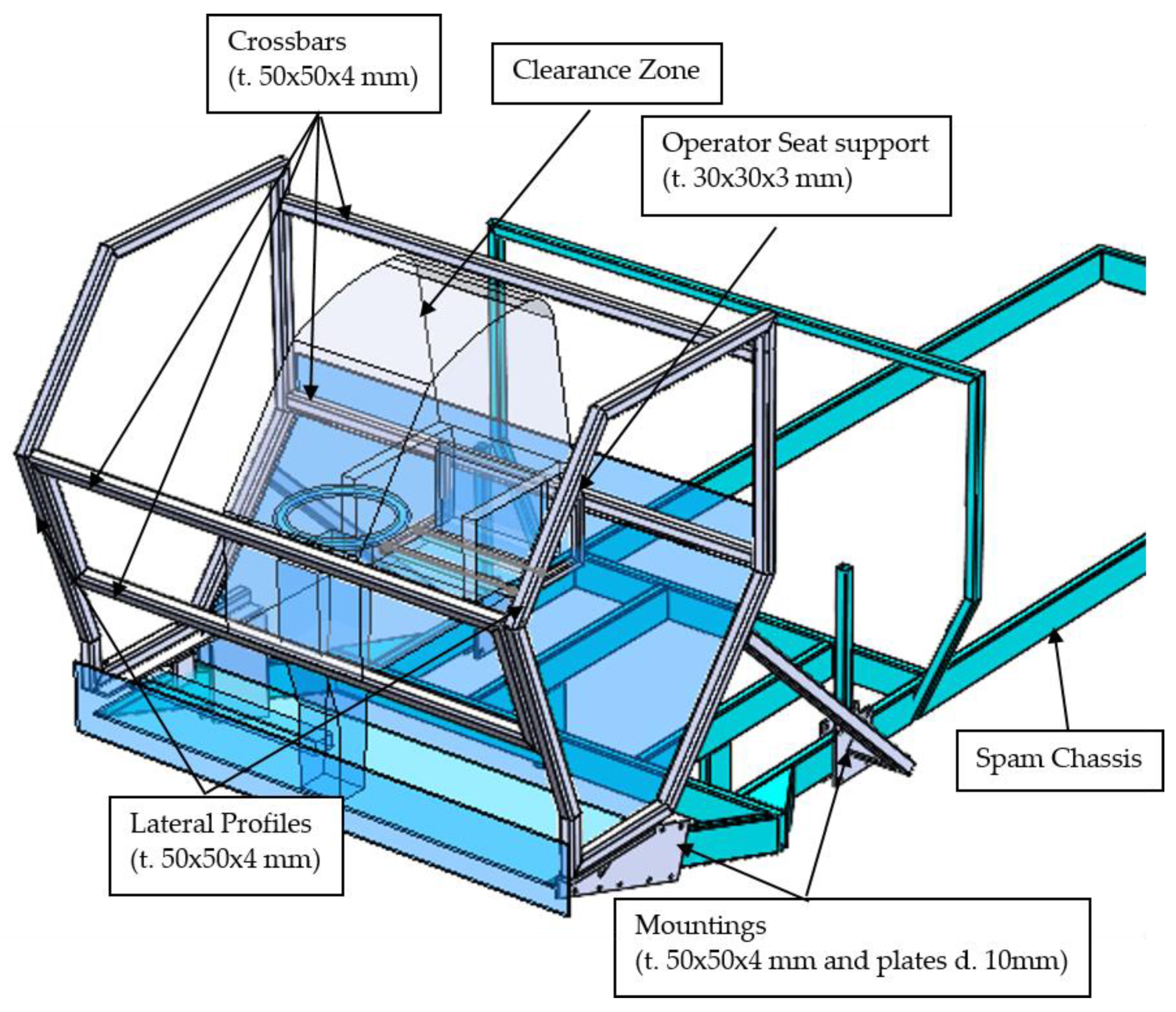
Another criticality emerged, since, due to the large mass of this machine, the protective structure should be a four-post type, but no solid fastening zones could be found. Additionally, unlike the earth-moving machine, the operator seat was positioned between the cutting bar and the tank, i.e., too far ahead from the chassis of the machine. Moreover, considering the SPS features of the machine, it was noted that the structure of the machine itself can provide sufficient protection only in case of back or side roll-over. Hence, following the procedure illustrated in Section 3, the normative framework was analyzed to depict a feasible solution. In particular, based on the machinery features and stability characteristics, a two pillars structure type was chosen, adapting the ISO 12117-2:2008 standard, which provides the requirements for laboratory tests and performance requirements for protective structures of excavators over 6 t [38]. In particular, as suggested by EN 474-5:2006 + A3:2013 for hydraulic excavators with an operating mass over 6 t and less than 50 t, ISO 12117-2 should be used for evaluation of the performance of the TOPS. Accordingly, the reverse engineering approach led the authors to develop a TOPS device similar to those used for earth-moving machinery (e.g., hydraulic excavators) and to anchor the system to the circled zones, as shown in Figure 11.
The TOPS structure shown in Figure 11 was then implemented by means of CAE tools for virtual prototyping and testing, considering the energy and force parameters defined by the ISO 12117 standard to test the structure (side loading and an optional longitudinal loading, as indicated in Table 5).
Following the same procedure as in the previous case study, in the following sub-sections we describe the structural verification of the TOPS model that was carried out considering the test loads of the ISO 12117 standard. Such an analysis aimed at verifying the protection of the operator’s deflection limiting volume (DLV) by the TOPS. In other words, the following simulations followed the sequence indicated in Table 5 and were aimed at verifying that during the loading phases no part of the TOPS entered or unprotected the DLV.
4.2.1. Side Loading
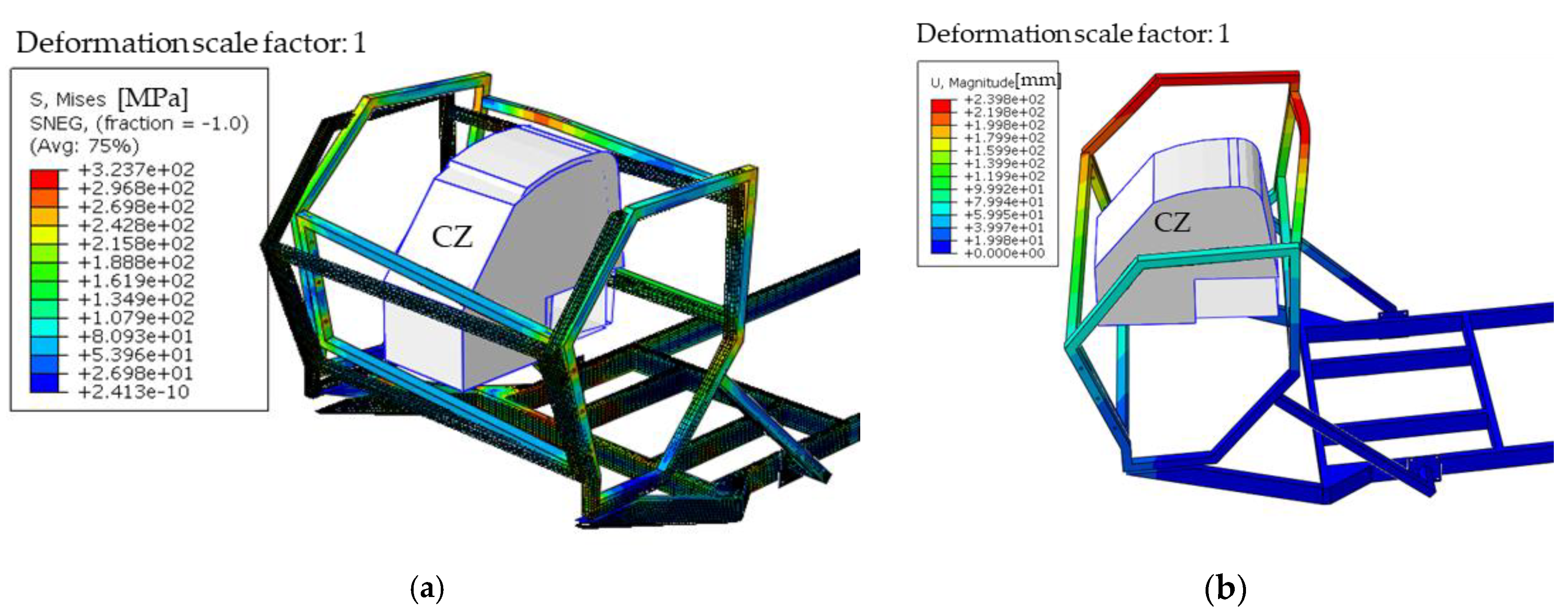
Figure 12 shows the effect of side loading on the TOPS structure in terms of Von Mises stress:
- The deflection limiting volume is protected;
- The maximum level of stress is under the ultimate stress limit of the material (see Table 3).
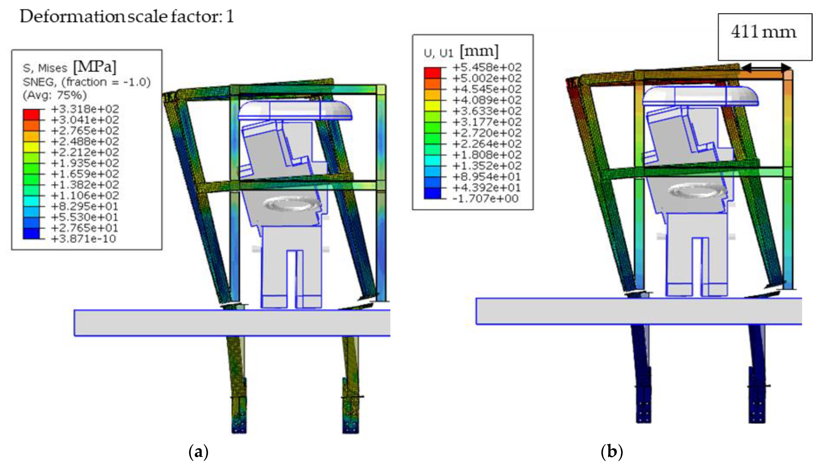
4.2.2. Longitudinal Loading
Figure 13 shows the contour plot of Von Mises stress at the end of the front loading with the non-deformed shape superimposed on the deformed one. The FEM analysis pointed out that: the deflection limiting volume (DLV) was protected and within the boundaries of TOPS, nor did any part of the TOPS reach the ultimate tensile strength of the material.
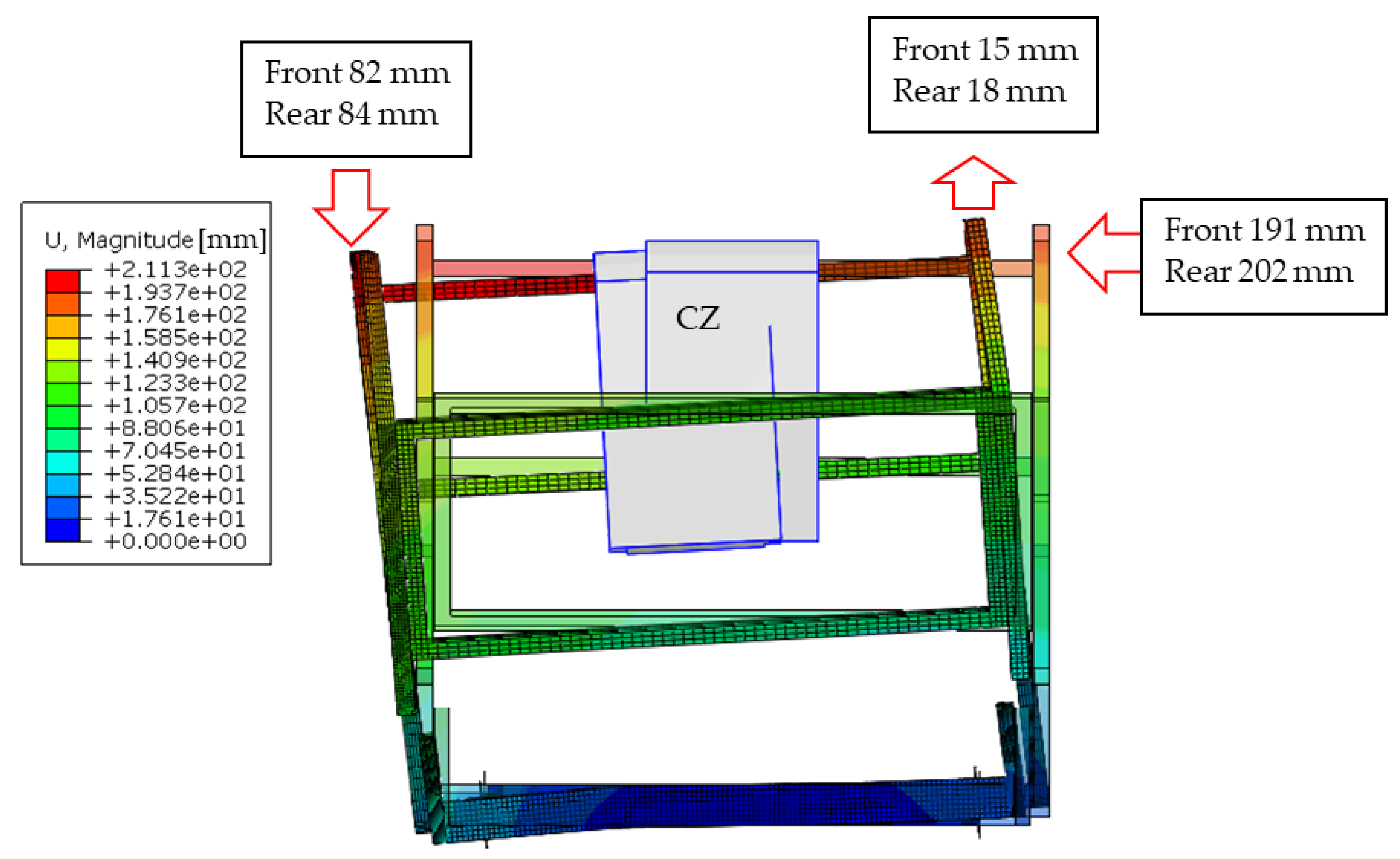
4.2.3. Permanent Deflection
Figure 14 shows the permanent deflection values of the ROPS fitted on the combine harvester, resulting after the side loading and longitudinal loading tests. The DLV is protected even if the structure undergoes major deformation due to its considerable height (more than 2500 mm). Such a situation underlines the difficulty in equipping this kind of machine with a ROPS-type structure. In fact, the tests foreseen for the ROPS-type structures are stricter than the tests for the TOPS-type structures because of the presence of crushing tests and higher values of required energy and forces. This confirms the need of developing an ad hoc testing procedure for the combine harvester, which can be used to implement a retrofitting program effectively.
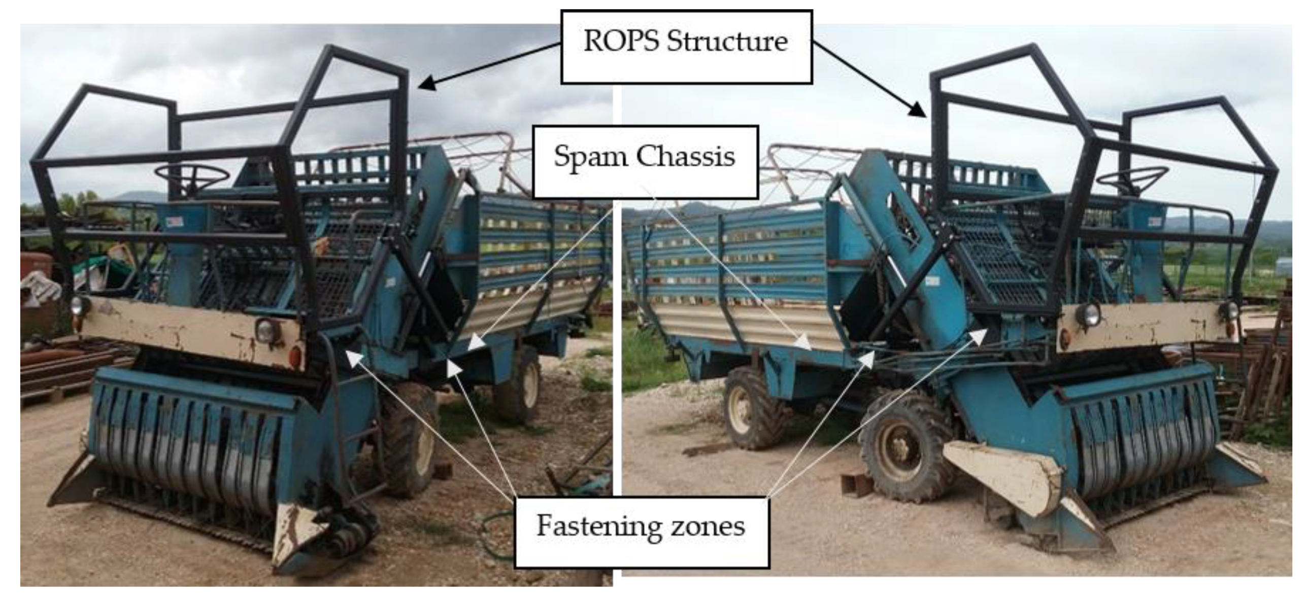
4.2.4. Protective Structure Building and Functional Testing
Finally, on the basis of the positive results obtained with CAD model and FEM simulations (i.e., the TOPS can support the machine in the position caused by the tipping over without entering the DLV), a physical prototype of the TOPS was realized and installed on the machine (see Figure 15) to verify the practical adaptation of the solution provided.
5. Discussion of Results and Conclusions
The aim of the paper is to provide both a reference procedure to be used in the risk assessment analysis of SPAM’s protective structures and technical information to manufacture and install these protective structures on old agricultural machinery.
The results achieved by means of the two case studies described in the previous section show the reliability of the proposed procedure for the development of ad hoc protective structures of machinery that have been put on the market unprotected due to a lack of a safety normative reference. Although this problem is very diffused in the field of agricultural machinery, most studies in the literature focused on agricultural tractors focus both on the development of aftermarket ROPS structures [39,40,41] and the promotion of retrofitting programs [42,43,44], while scarce attention has been paid to other types of machinery [14].
Hence, the present study aims at providing a first response to such a gap. More in detail, in accordance with the proposed procedure, the authors adapted the OECD Code 4 to a forage harvester. While adapting the ISO 12117-2:2008 standard, which provides the requirements for laboratory tests and performance requirements for protective structures of excavators over 6 t, the use of a TOPS is for the first time introduced as protective structure for a combine harvester in case of loss of stability.
In particular, considering the forage harvester, the OECD Code 4 appears suitable for the machine with a chassis and with a comparable mass to tractor carrier type. The analysis pointed out that a standard configuration with a closed steel structure including the operator seat support must be considered, since in this way, the operator is rigidly attached to a safety space and the frame of the machine stores all the energy derived from a roll-over event.
On the other hand, the retrofit of the combine harvester strengthens the need to develop a dedicated standard for this type of machine, although it is possible to adopt a structure that can reduce damages to the operator in case of tip-over. In this case, it must be noted that the machine is stable with respect the ISO 16231 standard, even though the limits established by this standard are questionable, since they are not related to the practical use of the machinery also on slopes [26].
The reliability of the proposed protective structures was checked by applying the finite element calculation method to simulate the expected test loads. The results showed that the proposed approach is suitable for retrofitting forage harvesters and combine harvesters, as well as other similar machinery. Actually, considering the machines’ features and the protection capacity of the developed structures, the approach proposed in this study can represent a useful indication for the adaptation of a large part of self-propelled agricultural machinery already in use.
In summary, the study provided a methodology for the development of ROPS/TOPS solutions for SPAMs, aiming at reducing the lack of research and technical references in this specific context. Computer simulations and experimental tests were carried out to verify the effectiveness of the above criteria and the results achieved showed their reliability, expanding knowledge on safety issues of this type of machinery and the related operator’s protective structures in case of roll-over or tip-over. These results can be considered as a basis of a general framework for the implementation of ROPS/TOPS retrofitting measures of SPAM, considering that SPAMs as work equipment have to be updated to reduce the risks of operators in case of the loss of stability, in accordance with the provisions of the directive 2009/104/EC.
Accordingly, this contribution is more relevant to practice in this sector, but it is also useful to advance scientific knowledge on ontologies in the adoption of safety improvement solutions for machinery that is also used in different contexts and domains. Actually, as stressed by Urbanic and El Maraghy [45], effective solutions can be found when a component/part of a technical system has to be designed rather than adapted, as in the case of ROPS/TOPS. This accomplishes the research hints of Casazza et al. [46].
Overall, these findings are in line with Caffaro et al. [47], who underlined that occupational health and safety (OHS) must be considered from both the equipment user’s and manufacturer’s point of view, finding new strategies to reduce accidents associated with the use of hazardous machinery. This also accomplishes the research hints by Kogler et al. [48], who highlighted the importance of providing information tools, such as procedures, aimed at improving the safety level of farmers.
Hence, this study can provide a basis for further development of the proposed procedure for practitioners in this type of industry as well as in other domains where the use of self-propelled machinery represents a high risk for operators such as mining and construction [31,32]. Finally, it should be remarked that the results of this study will be used to foster the SPAMs’ ROPS/TOPS retrofitting campaign promoted by the National Institute for Insurance against Accidents at Work (INAIL).
Author Contributions
Conceptualization, L.V. and D.G.; methodology, L.V., D.P. and D.G.; software, D.G.; validation, D.P. and L.V.; writing—review and editing, L.V. and D.G. All authors have read and agreed to the published version of the manuscript.
Funding
This research received no external funding.
Institutional Review Board Statement
Not applicable.
Informed Consent Statement
Not applicable.
Data Availability Statement
Not applicable.
Conflicts of Interest
The authors declare no conflict of interest.
References
- Burgus, S.; Duysen, E. Identifying Topics and Dissemination Methods for Agricultural Safety and Health Messages. Safety 2017, 3, 3. [Google Scholar] [CrossRef] [Green Version]
- Jenkins, P.L.; Sorensen, J.A.; Yoder, A.; Myers, M.; Murphy, D.; Cook, G.; Wright, F.; Bayes, B.; May, J.J. Prominent barriers and motivators to installing ROPS: An analysis of survey responses from Pennsylvania and Vermont. J. Agric. Saf. Health 2012, 18, 103–112. [Google Scholar] [CrossRef]
- Chae, H.; Min, K.; Park, J.; Kim, K.; Kim, H.; Lee, K. Estimated rate of agricultural injury: The Korean farmers’ occupational disease and injury survey. Ann. Occup. Environ. Med. 2014, 26, 8. [Google Scholar] [CrossRef]
- Kumar, A.; Varghese, M.; Mohan, D. Equipment-related injuries in agriculture: An international perspective. Inj. Control Saf. Promot. 2000, 7, 175–186. [Google Scholar] [CrossRef]
- Cividino, S.R.S.; Pergher, G.; Zucchiatti, N.; Gubiani, R. Agricultural Health and Safety Survey in Friuli Venezia Giulia. Agriculture 2018, 8, 9. [Google Scholar] [CrossRef] [Green Version]
- Pessina, D.; Facchinetti, D. A survey on fatal accidents for overturning of agricultural tractors in Italy. Chem. Eng. Trans. 2017, 58, 79–84. [Google Scholar]
- Fargnoli, M.; Lombardi, M.; Haber, N.; Puri, D. The Impact of Human Error in the Use of Agricultural Tractors: A Case Study Research in Vineyard Cultivation in Italy. Agriculture 2018, 8, 82. [Google Scholar] [CrossRef] [Green Version]
- Keskin, S.G.; Keskin, M.; Soysal, Y. Assessing farm tractor incidents and awareness levels of operators for tractor safety issues in the Hatay province of Turkey. J. Agric. Saf. Health 2012, 18, 113–128. [Google Scholar] [CrossRef] [PubMed]
- Il Quadro Degli Infortuni-Elementi di Riflessione. Available online: http://www.dinamica-fp.com/images/dinamica/sicuragri/quadroinfortuni.html (accessed on 15 March 2021).
- Myers, M.L. Tractor risk abatement and control as a coherent strategy. J. Agric. Saf. Health 2002, 8, 185–198. [Google Scholar] [CrossRef] [PubMed] [Green Version]
- Cecchini, M.; Monarca, D.; Laurendi, V.; Puri, D.; Cossio, F. Mechatronic Solutions for the Safety of Workers Involved in the Use of Manure Spreader. Agriculture 2017, 7, 95. [Google Scholar] [CrossRef] [Green Version]
- Mayrhofer, H.; Quendler, E.; Boxberger, J. Prevention aspects for avoiding run-over incidents with self-propelled agricultural machinery. CIGR J. 2014, 16, 148–156. [Google Scholar]
- Fargnoli, M.; Lombardi, M.; Haber, N. A fuzzy-QFD approach for the enhancement of work equipment safety: A case study in the agriculture sector. Int. J. Reliab. Saf. 2018, 12, 306–326. [Google Scholar] [CrossRef]
- Fargnoli, M.; Lombardi, M.; Puri, D. Applying Hierarchical Task Analysis to Depict Human Safety Errors during Pesticide Use in Vineyard Cultivation. Agriculture 2019, 9, 158. [Google Scholar] [CrossRef] [Green Version]
- Yoder, A.M.; Sorensen, J.A.; Foster, F.; Myers, M.; Murphy, D.; Cook, G.; May, J.; Jenkins, P. Selecting Target Populations for ROPS Retrofit Programs in Pennsylvania and Vermont. J. Agric. Saf. Health 2013, 19, 175–190. [Google Scholar] [PubMed]
- Fargnoli, M.; Laurendi, V.; Tronci, M. Design for Safety in Agricultural Machinery. In DS 60, Proceedings of the DESIGN 2010, the 11th International Design Conference, Dubrovnik, Croatia, 17–20 May 2010; Marjanovic, D., Storga, M., Pavkovic, N., Bojcetic, N., Eds.; International Design Conference: Dubrovnik, Croatia, 2010; pp. 701–710. ISBN 978-953-7738-03-7. [Google Scholar]
- Fargnoli, M.; Vita, L.; Gattamelata, D.; Laurendi, V.; Tronci, M. A Reverse Engineering Approach to Enhance Machinery Design for Safety. In DS 70, Proceedings of the DESIGN 2012, the 12th International Design Conference, Dubrovnik, Croatia, 21–24 May 2012; Marjanovic, D., Storga, M., Pavkovic, N., Bojcetic, N., Eds.; International Design Conference: Dubrovnik, Croatia, 2012; pp. 627–636. ISBN 978-953-7738-17-4. [Google Scholar]
- Pessina, D.; Facchinetti, D.; Giordano, D.M. Narrow-track agricultural tractors: A survey on the load of the hand-operated foldable rollbar. J. Agric. Saf. Health 2016, 22, 275–284. [Google Scholar]
- Italian Workers Compensantion Authority (INAIL) Guidelines for ROPS Retrofitting on Old Agricultural Tractors. Available online: https://www.inail.it/cs/internet/comunicazione/pubblicazioni/catalogo-generale/linstallazione-dei-dispositivi-di-protezione.html (accessed on 28 February 2021).
- International Organization for Standardization (ISO). ISO 16231-1:2013-Self-Propelled Agricultural Machinery—Assessment of stability—Part 1: Principles. Available online: https://www.iso.org/standard/55941.html (accessed on 1 March 2021).
- International Organization for Standardization (ISO). ISO 16231-2:2015-Self-Propelled Agricultural Machinery-Assessment of Stability-Part 2: Determination of Static Stability and Test Procedures. Available online: https://www.iso.org/standard/61583.html (accessed on 1 March 2021).
- OECD Standards Code 4, 6, 7, 8 for the Official Testing of Roll-over Protective Structures on Agricultural and Forestry Tractors, Organisation for the Economic Co-Operation and Development Paris, France. Available online: https://www.oecd.org/agriculture/tractors/codes/ (accessed on 28 February 2021).
- Capacci, E.; Rondelli, V. Evaluation of Testing Procedures for ROPS Fitted on Self-propelled Agricultural Machinery. In Proceedings of the International Conference Work Safety and Risk Prevention in Agro-Food and Forest Systems, Ragusa SHWA 2010, Ragusa, Italy, 16–18 September 2010; pp. 202–209. [Google Scholar]
- Pessina, D.; Facchinetti, D.; Giordano, D. The Driver’s Protection in Case of Self-Propelled Machinery Roll-Over. Contemp. Eng. Sci. 2015, 8, 1127–1140. [Google Scholar] [CrossRef] [Green Version]
- Capacci, E.; Franceschetti, B.; Ciuffoli, A.; Rondelli, V. The stability of self-propelled sprayers according to the ISO 16231 standardized procedure. Chem. Eng. Trans. 2017, 58, 61–66. [Google Scholar]
- Gattamelata, D.; Laurendi, V.; Vita, L.; Fargnoli, M.; Pirozzi, M. Roll-Over Risk Analysis for Agricultural Self-Propelled Ride-On Machines. In Proceedings of the International Conference RAGUSA SHWA, Ragusa, Italy, 3–6 September 2012; Volume 4. [Google Scholar]
- OECD Document TAD/CA/T/WD(2012)7, Report from the Sub-Working Group (SWG) on the Extension of ROPS to other Agricultural Machinery. In Proceedings of the OECD, Organisation for the Economic Co-Operation and Development, Paris, France, 9–30 May 2013.
- Mayrhofer, H.; Quendler, E.; Boxberger, J. Narrative text analysis of accident reports with tractors, self-propelled harvesting machinery and materials handling machinery in Austrian agriculture from 2008 to 2010-a comparison. Ann. Agric. Environ. Med. 2014, 21, 183–188. [Google Scholar] [PubMed]
- Al-Bassit, L.; Tricot, N.; Sayegh, S. Falling-object protective structure for tractors in service: Prototype design and validation. Biosyst. Eng. 2019, 185, 76–87. [Google Scholar] [CrossRef]
- Rondelli, V.; Casazza, C.; Martelli, R. Tractor rollover fatalities, analyzing accident scenario. J. Saf. Res. 2018, 67, 99–106. [Google Scholar] [CrossRef]
- Fargnoli, M.; Lombardi, M.; Haber, N.; Guadagno, F. Hazard function deployment: A QFD-based tool for the assessment of working tasks—A practical study in the construction industry. Int. J. Occup. Saf. Ergon. 2020, 26, 348–369. [Google Scholar] [CrossRef] [PubMed]
- Karlinski, J.; Rusinski, E.; Smolnicki, T. Protective structures for construction and mining machine operator. Autom. Constr. 2008, 17, 232–244. [Google Scholar] [CrossRef]
- Derlukiewicz, D.; Karlinski, J.; IIuk, A. The operator protective structures testing for mining machines. Solid State Phenom. 2010, 165, 256–261. [Google Scholar] [CrossRef]
- Afeez, A.; Kumar, A. Application of CAD and reverse engineering methodology for development of complex assemblies. J. Eng. Des. Technol. 2013, 11, 375–390. [Google Scholar] [CrossRef]
- Karlinski, J.; Ptak, M.; Działak, P. Simulation tests of roll-over protection structure. Arch. Civil Mech. Eng. 2013, 13, 57–63. [Google Scholar] [CrossRef]
- Wang, X.; Ayers, P.; Womac, A.R. Static simulation and analyses of mower’s ROPS behavior in a finite element model. J. Agric. Saf. Health 2009, 15, 335–351. [Google Scholar] [CrossRef] [PubMed]
- Italian Workers Compensation Authority (INAIL) Guidelines for ROPS Retrofitting on Old Agricultural Carrying Tractors. Available online: https://www.inail.it/cs/internet/attivita/prevenzione-e-sicurezza/promozione-e-cultura-della-prevenzione/linee-guida/ucm_portstg_077603_dispositivi-di-protezione-del-conducente.html (accessed on 8 February 2021).
- Mechanical Properties of Materials. Available online: https://mechanicalc.com/reference/mechanical-properties-of-materials#ramberg-osgood-equation, (accessed on 25 March 2021).
- International Organization for Standardization (ISO). ISO 12117-2:2008-Earth-Moving Machinery—Laboratory Tests and Performance Requirements for Protective Structures of Excavators—Part 2: Roll-Over Protective Structures (ROPS) for Excavators of over 6 t. Available online: https://www.iso.org/standard/43160.html (accessed on 1 March 2021).
- Harris, J.R.; McKenzie, E.A.; Etherton, J.R.; Cantis, D.M.; Ronaghi, M. ROPS performance during field upset and static testing. J. Agric. Saf. Health 2010, 16, 5–18. [Google Scholar] [CrossRef] [PubMed]
- Franceschetti, B.; Rondelli, V.; Ciuffoli, A. Comparing the influence of roll-over protective structure type on tractor lateral stability. Saf. Sci. 2019, 115, 42–50. [Google Scholar] [CrossRef]
- Fargnoli, M.; Lombardi, M. Safety Vision of Agricultural Tractors: An Engineering Perspective Based on Recent Studies (2009–2019). Safety 2020, 6, 1. [Google Scholar] [CrossRef] [Green Version]
- Hard, D.L.; Myers, J.R. Adoption of rollover protective structures (ROPS) on US farm tractors by state: 1993–1995, 2001, and 2004. J. Agric. Saf. Health 2011, 17, 157–172. [Google Scholar] [CrossRef]
- Hard, D.L.; McKenzie, E.A.; Cantis, D.; May, J.; Sorensen, J.; Bayes, B.; Madden, E.; Wyckoff, S.; Stone, B.; Maass, J. A demonstration project in New York and Virginia: Retrofitting cost-effective roll-over protective structures (CROPS) on tractors. J. Agric. Saf. Health 2015, 21, 173–185. [Google Scholar] [CrossRef] [PubMed] [Green Version]
- Urbanic, R.J.; ElMaraghy, W. A design recovery framework for mechanical components. J. Eng. Des. 2009, 20, 195–215. [Google Scholar] [CrossRef]
- Casazza, C.; Martelli, R.; Rondelli, V. Evaluation of a commercial tractor safety monitoring system using a reverse engineering procedure. J. Agric. Saf. Health 2016, 22, 215–225. [Google Scholar] [PubMed] [Green Version]
- Caffaro, F.; Micheletti Cremasco, M.; Roccato, M.; Cavallo, E. It does not occur by chance: A mediation model of the influence of workers’ characteristics, work environment factors, and near misses on agricultural machinery-related accidents. Int. J. Occup. Environ. Health 2017, 23, 52–59. [Google Scholar] [CrossRef] [PubMed]
- Kogler, R.; Quendler, E.; Boxberger, J. Occupational accidents with agricultural machinery in Austria. J. Agromed. 2016, 21, 61–70. [Google Scholar] [CrossRef] [PubMed]
Figure 1.
SPAM loss of stability during field operation: (a) roll-over; (b) tip-over.
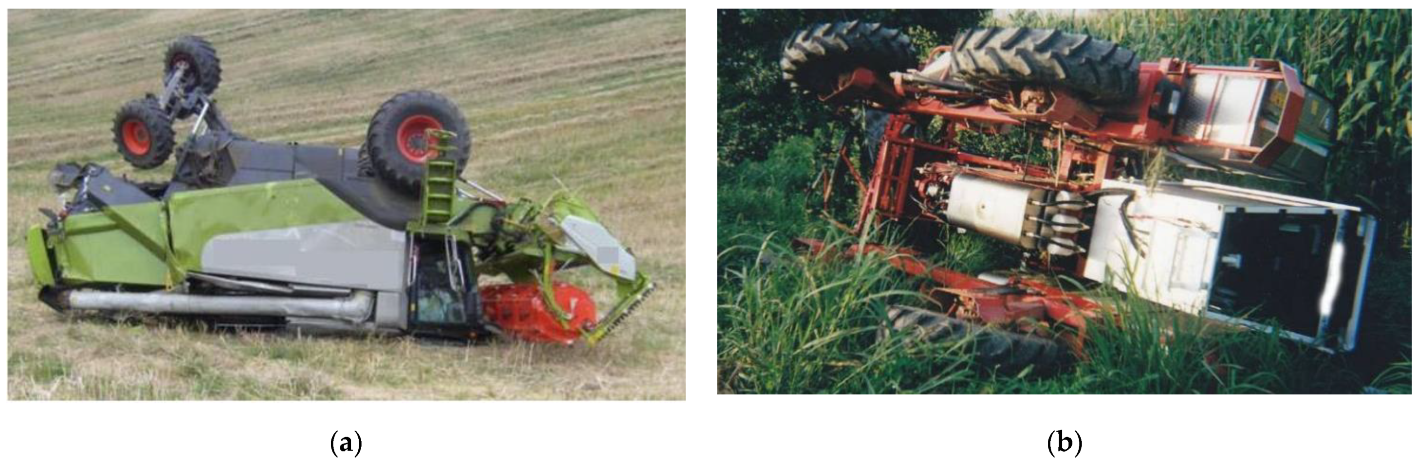
Figure 2.
Structural elements of a combine harvester that should protect the operator in case of roll-over.
Figure 2.
Structural elements of a combine harvester that should protect the operator in case of roll-over.

Figure 3.
Decision-making flow chart depicting tools and activities involved in the ROPS/TOPS development.
Figure 3.
Decision-making flow chart depicting tools and activities involved in the ROPS/TOPS development.
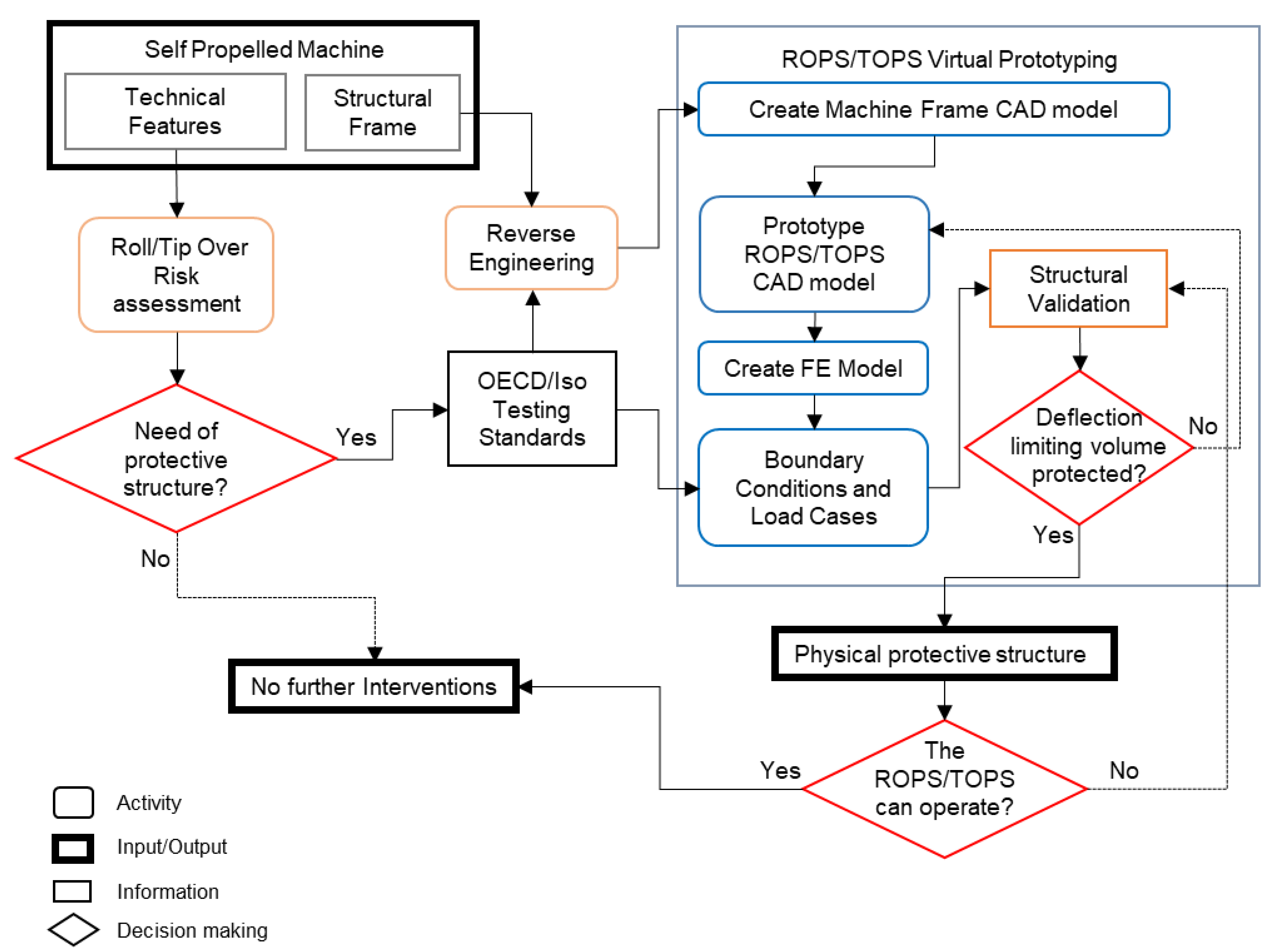
Figure 4.
Spam forage harvester ROPS elements.

Figure 5.
Longitudinal loading effects on ROPS and the clearance zone: (a) contour plot of Von Mises stress (expressed in MPa), 3D view; (b) displacement contour plot, 3D view without undeformed shape superimposition (expressed in mm).
Figure 5.
Longitudinal loading effects on ROPS and the clearance zone: (a) contour plot of Von Mises stress (expressed in MPa), 3D view; (b) displacement contour plot, 3D view without undeformed shape superimposition (expressed in mm).

Figure 6.
Side loading ROPS and clearance zone: (a) rear-view contour plot of Von Mises stress (expressed in MPa); (b) top-view displacement contour plot (expressed in mm).
Figure 6.
Side loading ROPS and clearance zone: (a) rear-view contour plot of Von Mises stress (expressed in MPa); (b) top-view displacement contour plot (expressed in mm).

Figure 7.
Crushing effects attained at the maximum required load, lateral view of ROPS and clearance zone: (a) contour plot of Von Mises stress, first crushing, without undeformed shape superimposition (expressed in MPa); (b) contour plot of Von Mises stress second crushing (expressed in MPa).
Figure 7.
Crushing effects attained at the maximum required load, lateral view of ROPS and clearance zone: (a) contour plot of Von Mises stress, first crushing, without undeformed shape superimposition (expressed in MPa); (b) contour plot of Von Mises stress second crushing (expressed in MPa).
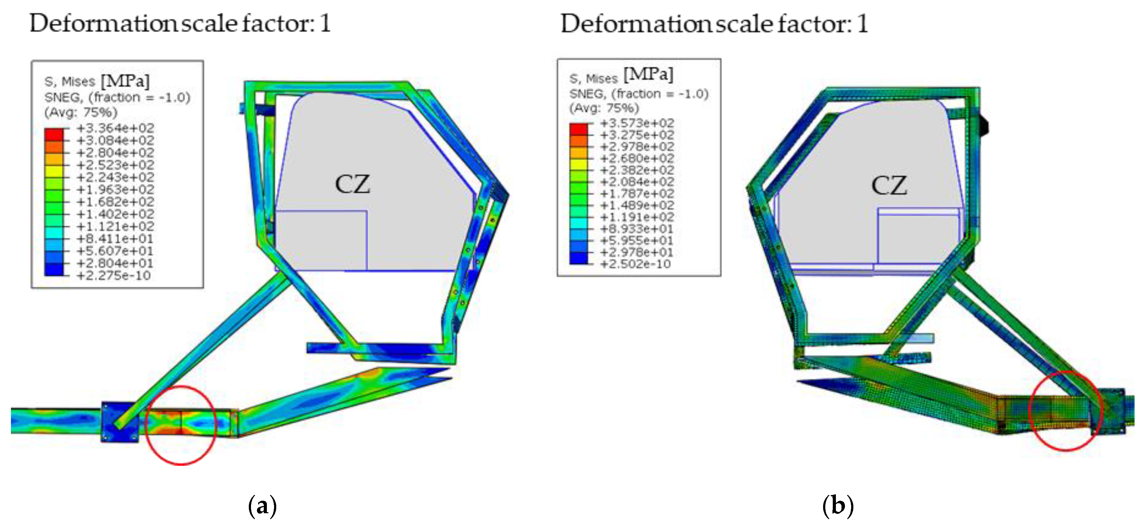
Figure 8.
Permanent deflection of the ROPS structure after the entire sequence of OECD Code 4 testing procedure: displacement contour plot front view with the clearance zone (expressed in mm).
Figure 8.
Permanent deflection of the ROPS structure after the entire sequence of OECD Code 4 testing procedure: displacement contour plot front view with the clearance zone (expressed in mm).

Figure 9.
The self-propelled forage harvester equipped with ROPS structure.

Figure 10.
Combine harvester technical data.
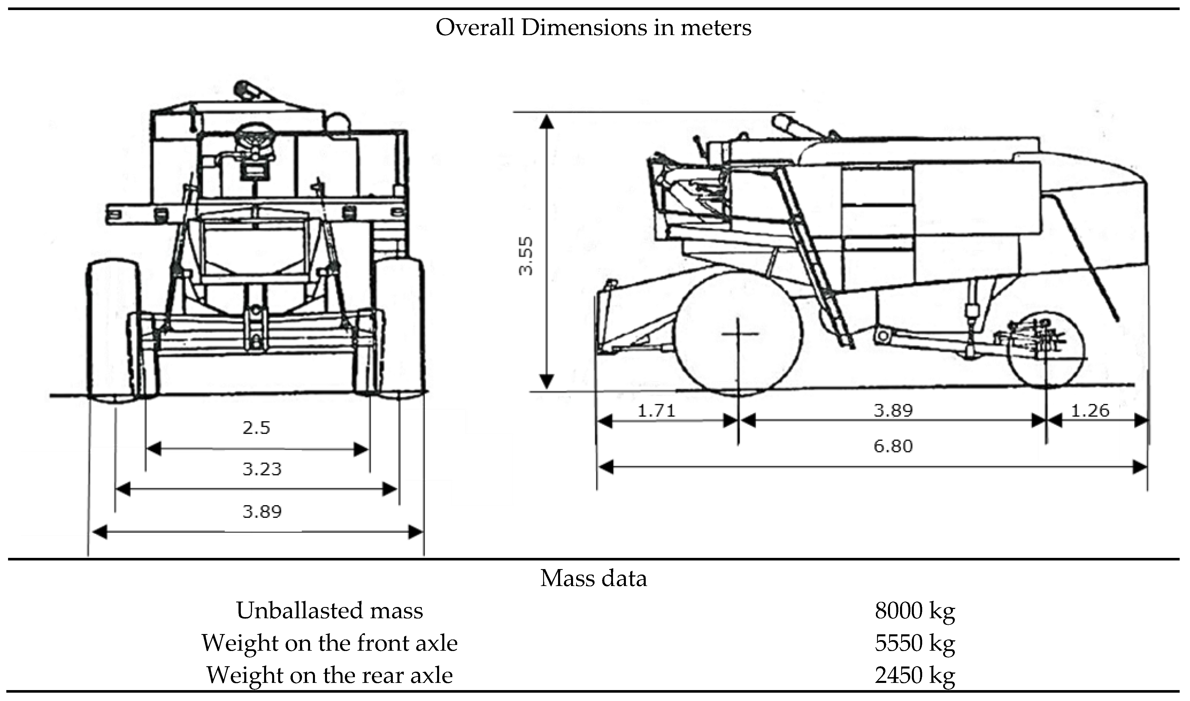
Figure 11.
Combine harvester TOPS structure: fastening zones and dimensional features in (mm).
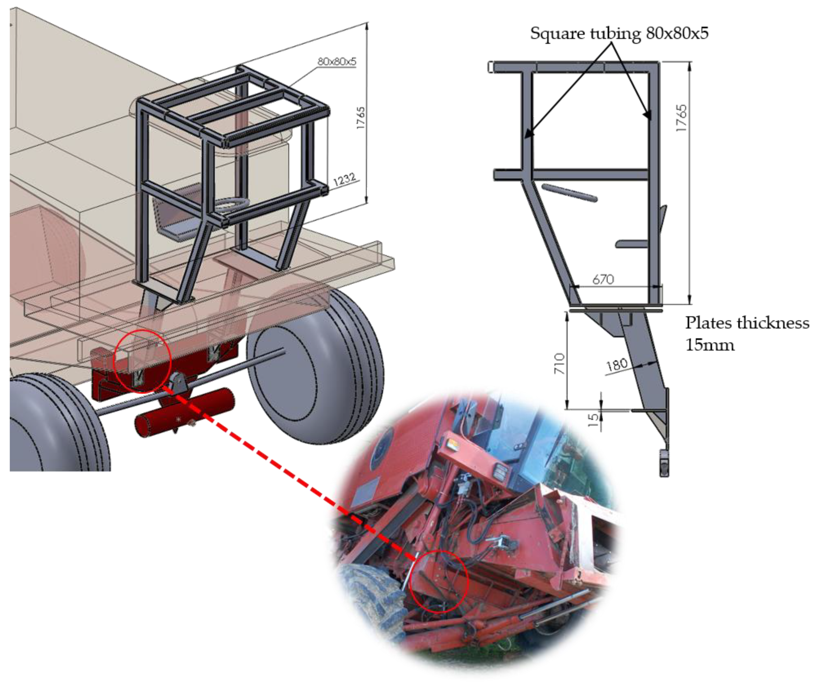
Figure 12.
Side loading front view of TOPS and deflection limiting volume: (a) contour plot of Von Mises stress (expressed in MPa); (b) displacement contour plot (expressed in mm) attained at the maximum required energy.
Figure 12.
Side loading front view of TOPS and deflection limiting volume: (a) contour plot of Von Mises stress (expressed in MPa); (b) displacement contour plot (expressed in mm) attained at the maximum required energy.

Figure 13.
Longitudinal loading lateral view: (a) contour plot of Von Mises stress (expressed in MPa); (b) displacement contour plot (expressed in mm) attained at the maximum required energy.
Figure 13.
Longitudinal loading lateral view: (a) contour plot of Von Mises stress (expressed in MPa); (b) displacement contour plot (expressed in mm) attained at the maximum required energy.
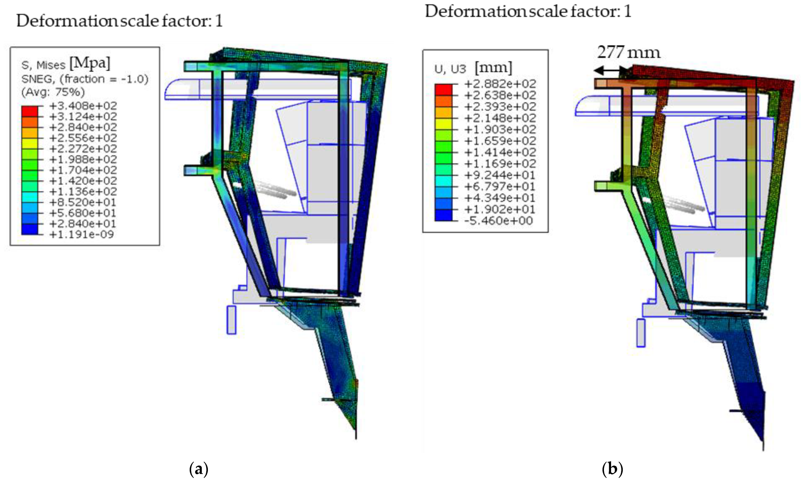
Figure 14.
Permanent deflection (expressed in mm) of the ROPS structure after the side and longitudinal loadings: (a) front view; (b) top view.
Figure 14.
Permanent deflection (expressed in mm) of the ROPS structure after the side and longitudinal loadings: (a) front view; (b) top view.
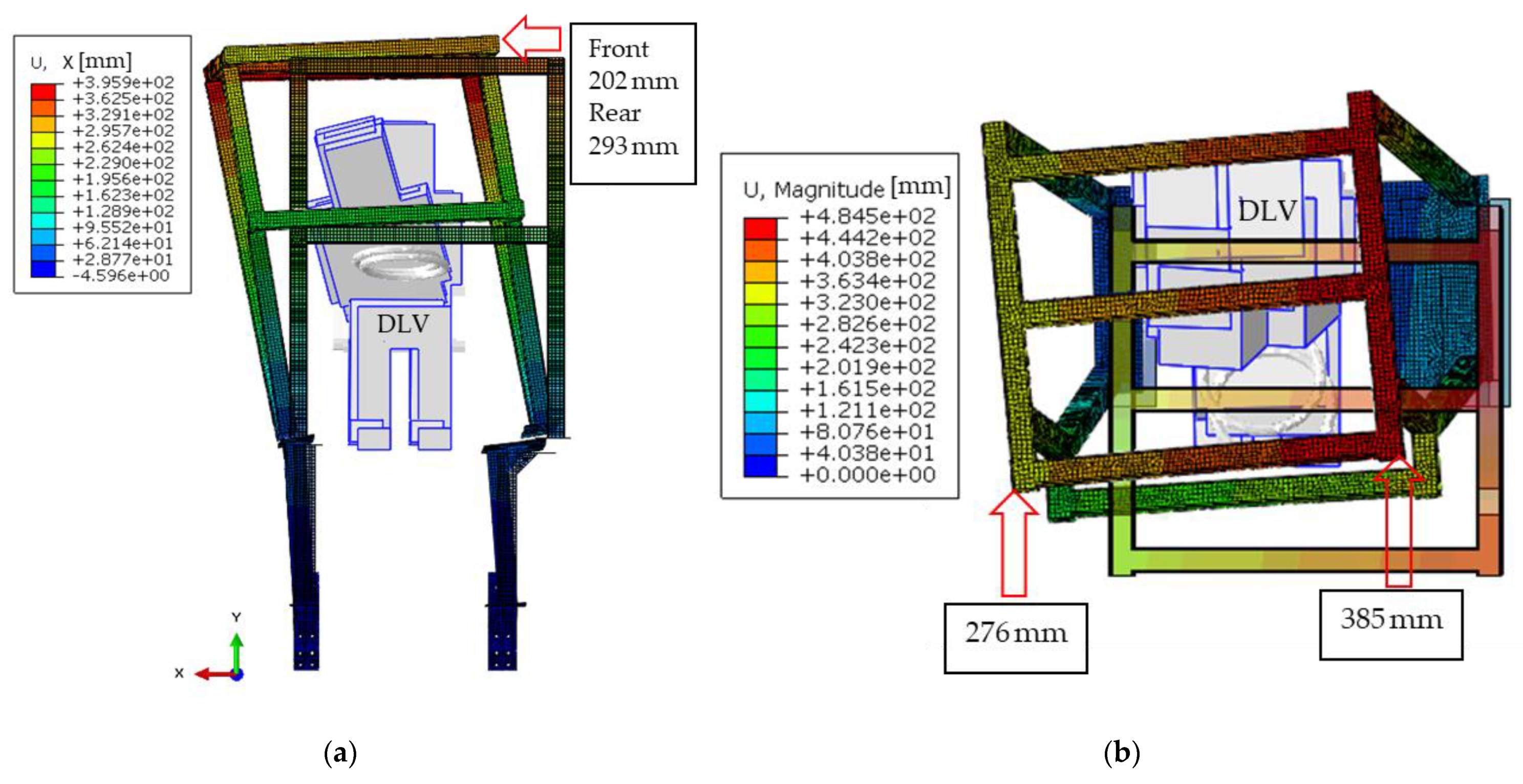
Figure 15.
Physical model of TOPS retrofitted on the combine harvester.


Table 1.
Main phases of protective structure manufacturing and fitting to machinery.
| Phase | Activities | Tools | Output |
|---|---|---|---|
| Detection of the machinery features | Detect the most relevant features with respect the loss of stability accidents: − machine inertial characteristics − machine main dimensions − presence of open or closed tanks − propulsion elements type − chassis topology | Weight scale; Gauge equipment | Machine data; Machine topology |
| Loss of stability risk assessment | Preliminary loss of stability hazard analysis according to the ISO 16231 standard calculation. Roll-over accidents data examination. | Standards ISO and OECD Codes | Define the protective structure type (ROPS/TOPS). Define the proper standard to test the protective structure. |
| Protective structure design | Analysis of the attachments on machine chassis. Reverse engineering of the anchorage points and potentially interfering elements. Machine virtual mockup. Protective structure virtual prototyping.Feasibility analysis of the protective structure. Structural validation. | CAE tools: CAD software (Solidworks); F.E.M. analysis software (Abaqus) | Protective structure virtual prototype; Workshop drawings. |
| Protective structure building and functional testing | Manufacturing of the protective structure. Protective structure fitting on SPAM. Test on the field. | Workshop tools; Carpentry material and fastenings; Protective structure evaluation on field | Valid protective structure. |
Table 2.
OECD Code 4—energy and force equations.
| Loading Sequence | Required Energy and Force | SPAM Tested |
|---|---|---|
| Longitudinal loading | 1.4 M = 3920 J | Applied force: on the front, right side Force = 23,746 N Energy = 4000 J |
| First crushing test | 20 M = 56,000 N | At rear 56,500 N |
| Side loading | 1.75 M = 4900 J | Applied force: on the left Force = 22,310 N Energy = 5136 J |
| Second crushing test | 20 M = 56,000 N | At the front 56,700 N |
Note: Reference mass M (kg).
Table 3.
Structural Steel S 275 mechanical properties.
| Property | Value | |
|---|---|---|
| Young’s Modulus | 210,000 MPa | |
| Poisson’s Ratio | 0.3 | |
| Plastic Behavior | Yield Stress [MPa] | Plastic Strain |
| 275 | 0 | |
| 290 | 0.0091 | |
| 330 | 0.0344 | |
| 360 | 0.1142 | |
| 370 | 0.2389 | |
| 430 | 0.7989 | |
Table 4.
SOA angle calculated on the basis of the ZCG values for combine harvester.
| SOA (deg) | |||
|---|---|---|---|
| 0 | 0 | ||
| 0 | 56.014 | 0 | 78.514 |
| 1 | 53.858 | 1 | 76.358 |
| 2 | 51.814 | 2 | 74.314 |
| 3 | 49.879 | 3 | 72.379 |
| 4 | 48.048 | 4 | 70.548 |
| 5 | 45.487 | 5 | 67.987 |
| 6 | 43.132 | 6 | 65.632 |
| 7 | 40.968 | 7 | 63.468 |
| 8 | 38.976 | 8 | 61.476 |
| 9 | 37.142 | 9 | 59.642 |
Table 5.
Energy and force values applied according to the provisions of the ISO 12117 standard.
| Loading Sequence | Required Energy | Achieved Energy | Applied Force |
|---|---|---|---|
| Side loading | 9835 J | 11,720 J | 29,580 N |
| Longitudinal loading | 3254 J | 3872 J | 17,700 N |
Publisher’s Note: MDPI stays neutral with regard to jurisdictional claims in published maps and institutional affiliations. |
© 2021 by the authors. Licensee MDPI, Basel, Switzerland. This article is an open access article distributed under the terms and conditions of the Creative Commons Attribution (CC BY) license (https://creativecommons.org/licenses/by/4.0/).
Share and Cite
MDPI and ACS Style
Vita, L.; Gattamelata, D.; Pessina, D. Retrofitting Agricultural Self-Propelled Machines with Roll-Over and Tip-Over Protective Structures. Safety 2021, 7, 46. https://0-doi-org.brum.beds.ac.uk/10.3390/safety7020046
AMA Style
Vita L, Gattamelata D, Pessina D. Retrofitting Agricultural Self-Propelled Machines with Roll-Over and Tip-Over Protective Structures. Safety. 2021; 7(2):46. https://0-doi-org.brum.beds.ac.uk/10.3390/safety7020046
Chicago/Turabian StyleVita, Leonardo, Davide Gattamelata, and Domenico Pessina. 2021. "Retrofitting Agricultural Self-Propelled Machines with Roll-Over and Tip-Over Protective Structures" Safety 7, no. 2: 46. https://0-doi-org.brum.beds.ac.uk/10.3390/safety7020046
Note that from the first issue of 2016, this journal uses article numbers instead of page numbers. See further details here.