
Safety and Reliability Analysis of an Ammonia-Powered Fuel-Cell System


Maritime Safety Research Centre, University of Strathclyde, Richmond Street 16, Glasgow G1 1XQ, UK
*
Author to whom correspondence should be addressed.
†
These authors contributed equally to the development and content of this paper.
Safety 2021, 7(4), 80; https://0-doi-org.brum.beds.ac.uk/10.3390/safety7040080
Submission received: 26 August 2021
/
Revised: 14 November 2021
/
Accepted: 18 November 2021
/
Published: 23 November 2021
Abstract
:Recently, the shipping industry has been under increasing pressure to improve its environmental impact with a target of a 50% reduction in greenhouse gas emissions by 2050, compared to the 2008 levels. For this reason, great attention has been placed on alternative zero-carbon fuels, specifically ammonia, which is considered a promising solution for shipping decarbonisation. In this respect, a novel ammonia-powered fuel-cell configuration is proposed as an energy-efficient power generation configuration with excellent environmental performance. However, there are safety and reliability concerns of the proposed ammonia-powered system that need to be addressed prior to its wider acceptance by the maritime community. Therefore, this is the first attempt to holistically examine the safety, operability, and reliability of an ammonia fuel-cell-powered ship, while considering the bunkering and fuel specifications. The proposed methodology includes the novel combination of a systematic preliminary hazard identification process with a functional and model-based approach for simulating the impact of various hazards. Furthermore, the critical faults and functional failures of the proposed system are identified and ranked according to their importance. This work can be beneficial for both shipowners and policymakers by introducing technical innovation and for supporting the future regulatory framework.
1. Introduction
1.1. Background
Awareness has grown recently of the progressive climate change starting two centuries ago. Over the last few centuries, climate change has become a reality, and societies have been facing its adverse effects. The level of global greenhouse gas (GHG) emissions has increased by more than 10% in the last decade [1], accelerating climate change. For this reason, during the last few decades, societies have been urged to adopt more environmentally friendly behaviours regarding their energy production and consumption. In addition, governments have taken action to introduce policies that promote sustainable development; in 2016, 196 nations signed the Paris Agreement at the United Nations Framework Convention on Climate Change, which aimed to reduce global warming below 2 °C [2]. At the same time, it is argued that there is a lag in the decarbonisation of the shipping industry [3], which is one of the fastest-growing industries in the world [4], as well as a significant contributor of anthropogenic emissions (3% in 2018) [5]. It is projected that, in 2050, the GHG emissions from ships will rise to higher levels than 2008, by approximately 130%, if this accelerating operational trend continues [5]. For this reason, following the Paris Agreement targets, the International Maritime Organisation (IMO) set a goal to reduce the carbon oxide emissions from the shipping sector by 70%, compared to the 2008 levels until 2050, as well as the GHG emissions by 50% [6].
As a result, significant attention and pressure has been placed on reducing the environmental impact and improving the energy efficiency of ships, from both academia and industry. Therefore, great focus is on alternative fuels [7,8,9,10,11,12] and more sustainable propulsion systems [13,14,15,16]. Specifically, attention has been paid to two carbon-neutral fuels, ammonia (NH3) [17,18,19,20,21] and hydrogen [22,23,24], and it is supported that the IMO 2050 goals could be reached mainly if carbon-neutral fuels contributed to 30–40% of the total energy required by ships [25].
1.2. Research Focus
Ammonia (NH3) is one of the most promising solutions for shipping decarbonisation [26,27], and there have recently been great efforts globally for green NH3 production [28]. It is a versatile fuel, with existing infrastructures [29], better energy density and safety characteristics, and less complexity in terms of storage than hydrogen [30]. NH3 can be combusted directly with a pilot fuel or used as a hydrogen vector in fuel cells (FC) [31], which is considered a promising alternative for marine propulsion with low environmental impact and high energy efficiency [32]. Specifically, a review of NH3-powered fuel cells indicated that solid oxide fuel cells (SOFCs) are currently the most promising technology for ammonia fuel [33]. SOFCs can use ammonia directly without cracking, which is an energy-consuming and challenging process [31].
As a result, a novel NH3-powered fuel-cell system is proposed as a potential solution for shipping decarbonisation [34]. However, NH3 as a marine fuel is still commercially immature [35], and, when introducing a novel propulsion system with new fuels, safety and reliability considerations need to be assessed [36,37]. This need is compounded when considering the hazardous and toxic characteristics of NH3 [38]. In addition, it is also indicated that the safety of shipboard fuel-cell systems is of paramount importance [39].
Therefore, in this study, a preliminary hazard identification and a safety analysis of an ammonia fuel-cell-powered plant, including the storage and feeding system, are proposed. The main hazards, critical faults, and functional failures of the proposed system are identified, and the reaction of the system to those hazards is assessed.
2. Critical Review
Frameworks and processes have been proposed to address the safety of novel designs and fuels in the maritime industry; the Formal Safety Assessment (FSA) is employed by IMO, for fleet-wide safety, whereas the Technology Qualification (TQ) process is proposed from Det Norske Veritas (DNV) for case-specific analysis. Both of the above identify the potential risks and hazards [40] and then evaluate their impact, to reduce the risks in the As Low as Reasonably Practicable (ALARP) region [40,41]. For clarity, in this work, hazard is defined as ‘the conditions with the potential to compromise safety’, whereas risk is calculated for the hazards and indicates ‘the likelihood and consequences of a future hazard event in a given context’ [42,43].
Various tools exist in the literature for assessing the safety, reliability, and operability of a system and establishing safeguards (summarised in Table 1). Two of the most used methods for safety assessment that help to systematically identify hazards and assess the operability of the system are Hazard Identification (HAZID) and the Hazard and Operability study (HAZOP) [40,44]. They are both applied as a knowledge-pooling exercise during a meeting that is typically held with the relevant parties and different shipping stakeholders. In HAZID, a brainstorm of potential hazards during the ship lifecycle is performed, while taking into account the current and upcoming regulations [45]. HAZID is a crucial process for the approval of alternative fuels and configurations, according to the International Code of Safety for Ships Using Gases (IGF) [46]. On the other hand, the HAZOP is a process to systematically evaluate the severity of deviations from normal operations of the system [42]. Consequently, HAZID focuses on identifying hazards in the design of the system, whereas HAZOP targets hazards related to the system’s operation. The design stage of a novel system is the most appropriate time to employ both tools and rely on the knowledge of experts [47].
Another tool commonly used for the safety and reliability assessment of new systems is fault-tree analysis (FTA) and failure modes, effects, and criticality analysis (FMECA) [48]. The former is a top-down approach that is initiated by stating an undesirable event [49]. It captures the functional dependencies within the examined system, and failure statistics for each component are used as inputs to examine the likelihood of the undesirable event [50]. On the other hand, FMECA can be employed to control risk by foresing possible failures during the design of a system, by examining the various ways a system can fail, and by identifying all the potential failure modes [48]. It also quantifies and ranks the criticality of each failure, caused by the various hazards.
Different applications of HAZID in the maritime industry can be found in the relevant literature, and thorough reviews regarding the merits of the available tools can be found in [51,52]. As argued in the previous sources, examining all the risks present in a system represents a genuine hurdle, which emphasises the significance of creating hybrid methods such as the one presented in this work. Focus has been placed on the risks related to natural gas hydrate transportation [53]. In addition, scholars have assessed the hazards of LNG dual-fuel ships [54,55,56]. On the other hand, hazards and operability analysis was carried out to assess the risk existing in the 10,000 TEU container ship in [57]. HAZID has also been used as part of the concept design stages for a nuclear-powered vessel [58], as well as for mooring and dynamic positioning systems in arctic conditions [59].
Failure mode analysis is widely used in many different sectors [60], with several publications summarising their different merits, shortcomings, and caveats [48,61]. In shipping, it has been employed to calculate appropriate maintenance tasks to improve the safety and reliability analysis of a hybrid system that includes fuel cells [62] or of a marine fuel oil system [63]. Similarly, FMEA/FMECA can be used to minimise downtime and improve reliability [64]. Furthermore, these tools have been used to create an integrated methodology combining FMEA with fuzzy logic for the reliability assessment of offshore marine assets [65]. The possible failure modes and effects of their occurrence in the fuel oil system of a marine diesel engine were investigated in [66]. On the other hand, a fuzzy FMECA approach was followed to identify the potential failure modes and hazards, as well as operability difficulties, of a marine boiler [67] or an oil tanker tank [68]. Lastly, the use of FMECA has also seen applications under the scope of the identification of critical equipment onboard merchant vessels [69].
In the existing literature, FTA has widespread applicability [50,70], with many publications reviewing the applicability of the method [71,72]. In the maritime sector, FTA was employed to investigate the availability of a large ethane carrier hybrid system that includes an ethane-powered SOFC for the electric demands of the vessel [73]. Others have investigated the safety enhancement of a cruise ship lubricating oil system using FTA [74]. The reliability of the marine propulsion system was investigated by employing FTA in [75]. Furthermore, a combination of FMECA and FTA methods was employed to assess the safety and reliability of a low-pressure LNG fuel feeding system [76]. In [77], the main engine lubricating oil system of an autonomous ship was assessed using FTA and FMEA methods. Lastly, FTA has also been used in conjunction with other tools for the identification of critical equipment of ships [78].

Table 1.
Tools for safety and reliability assessment of marine systems.
| Reference | Tool | System |
|---|---|---|
| [51,52] | HAZID/HAZOP | Review |
| [53] | HAZID | Natural gas hydrate carrier |
| [54,56] | HAZID | LNG fuelled vessel |
| [55] | HAZID | LNG carrier |
| [57] | HAZOP | Containership |
| [58] | HAZID | Nuclear-powered ship |
| [59] | HAZID | Mooring and positioning systems |
| [48,61] | FMEA/FMECA | Review |
| [62] | Layer of Protection Analysis & FMEA | Electric hybrid system |
| [63] | FMEA | Fuel oil system |
| [64] | FMEA/FMECA | Ship auxiliary systems |
| [65] | FMEA/FMECA | Offshore marine assets |
| [66] | FMEA | Fuel oil system |
| [67] | Fuzzy FMECA | Marine boiler |
| [68] | Fuzzy FMECA | Marine oil tanker |
| [69] | FMECA | Critical equipment of merchant vessels |
| [71,72] | FTA | Review |
| [73] | FTA | Hybrid system with SOFC |
| [74] | FTA | Lubricating oil system |
| [75] | FTA | Marine propulsion system |
| [76] | FMECA & FTA | LNG fuel feeding system |
| [77] | FMECA & FTA | Lubricating oil system |
| [78] | FTA | Critical equipment of merchant vessels |
In the existing literature of different sectors, when reviewing the safety and reliability of a novel system, such as a zero-carbon fuel-cell systems, a combination of FTA and failure mode analysis is indicated as a necessary step before commercialisation, since this technology is at an ‘infancy stage’ [79]. In other studies, the significance of FTA for the reliability assessment of a hybrid system, including fuel cells, was highlighted [80]. Furthermore, reviews on the different safety and risk assessment techniques indicate that it is challenging to account for all the risks in a system; thus, hybrid methods are required [51,52,81,82].
From the examined literature it is deduced that the design of novel ship systems requires the systematic identification of hazards and risks. This is optimally done using a holistic methodology for risk assessment that employs a combination of HAZID and HAZOP to address the hazards from the design and operation of the system [83]. In addition, a detailed reliability and safety analysis based on FTA and FMECA that identifies the critical components and failure modes is important for any novel hybrid system that employs emerging technologies and fuels. In general, a combination of different methods can provide a more accurate assessment of the risks in complex systems, such as the system proposed herein. However, as concluded from the analysis, there is a gap in a holistic safety assessment methodology that addresses both the design and the operability hazards, as well as identifies the critical components and failure modes of a marine ammonia fuel system.
For this purpose, a holistic safety approach is adopted for the proposed NH3 fuel-cell-powered system. This is the first study that examines the safety, operability, and reliability assessment of an NH3 fuel-cell-powered ship, as well as the NH3 bunkering, considering the fuel specifications. A HAZID for the identification of the functional hazards and a reaction of the system to these hazards is performed, as well as an FTA and FMECA for the identification of critical components and failure modes of the system.
The impact of this work herein is vital to understand the new safety requirements created by the introduction of NH3 as a marine fuel. This work aims to gain an understanding of the hazards of NH3-powered fuel cells, thereby establishing safety practices and preventing accidents. It should be noted that the focus of this work is on the safety analysis of the ammonia-powered system, not its operation. The outcome of this work is valuable for both shipowners and policymakers for introducing technical innovations, while also increasing the reliability of the proposed novel system. This is the first work to propose an NH3 fuel-cell-powered system for ocean-going vessel propulsion, it provides insight to shipowners regarding the safety concerns of using NH3 to develop the required safeguards. Second, even though there are numerous regulations ensuring the safe transportation of NH3 on ships, amendments are required to the IGF code for the use of NH3 for propulsion. Therefore, this work can be beneficial for the future regulatory framework.
In the next sections, the methodology employed for the safety and risk assessment of the NH3 fuel-cell-powered system is described, and the key findings are presented and then discussed.
3. Methodology
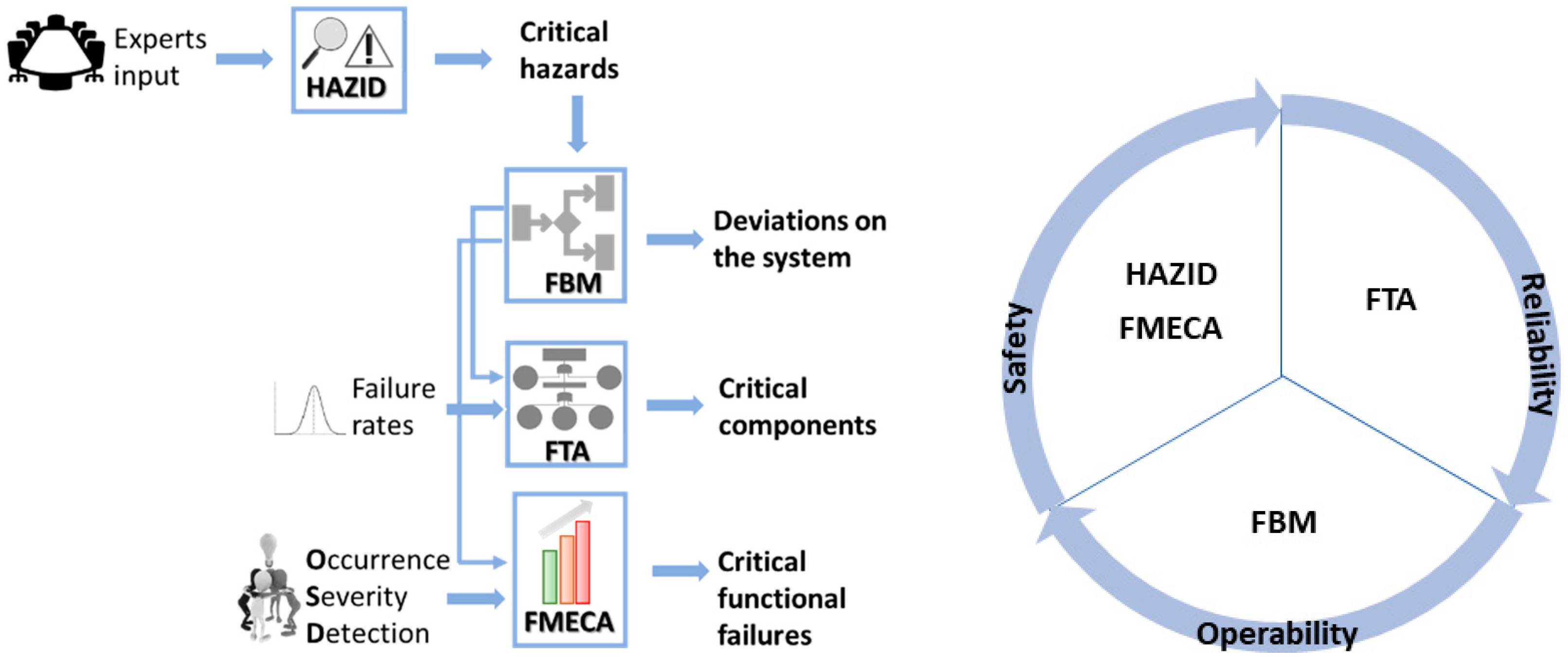
The developed model-based methodology for the safety assessment of an NH3 fuel system consists of four steps, presented in Figure 1. These steps ensure that the methodology identifies operation hazards, examines the reaction of the system to these hazards, and detects critical components and functional failures. First, a HAZID is performed with experts to identify the critical hazards of the system. These hazards are used as input by the developed functional-based modelling (FBM) to examine the system’s reaction to those hazards. Then, an FTA is performed taking into account the FBM of the system for the identification of critical components by evaluating the reliability of the system. Finally, an FMECA analysis is carried out and the functional failures of the components are derived. In summary, the compilation of the different tools used to assess the safety, operability, and reliability of the discussed novel system is presented in Figure 1.
As mentioned, the objective of the HAZID is to ensure that any risks arising from the installation and design of the novel NH3 SOFC system are under control and that adequate safeguards are in place to reduce these risks to ALARP region. It should be noted that hazards when at the yard for repairs/docking are outside the scope of this study. A workshop meeting with ship operators, equipment manufactures, and academic institutions was performed; experience from previous accidents was also considered. The results from the Sea-Web (IHS Markit) database indicated that most accidents were due to the use of ammonia in refrigeration systems; however, the quantities carried were much less compared to what is needed when ammonia is used as a primary fuel. Furthermore, in a few cases, the leakage of ammonia led to fatalities due to the fuel’s toxicity. An overview of the followed HAZID methodology is presented in Figure 2, in accordance with IACS document No. 146 [84].
The next step of the methodology is the creation of an FBM of the proposed system that depicts the architecture and functions of the system. Furthermore, FBM can be used to examine the reaction of a system to functional and hardware-based failures; as such, it can serve as a cornerstone for safety and risk assessments as seen in other research [74,76]. The Maintenance Aware Design environment (MADe) software from PHM Technology is a user-friendly model-based tool that has been used in various applications in the automotive and aviation industries for risk-based analysis including reliability, availability, and maintainability analysis [85,86,87]. It was employed in this work for the FBM development for the following reasons [86]:
- ▪
- It clearly depicts the systems, subsystems, and components, as well as their interconnections, and functions.
- ▪
- It allows the investigation of the propagation of failures within the system, thus supporting the identification of the system-critical components and their failure end-effects.
- ▪
- It serves as a starting point for additional analysis and examination.
In more detail, the examination of the behaviour of the system when subjected to various hazards is based on fuzzy cognitive mapping (FCM). FCM is used to rank the factors that affect the reliability of the system [88], by simultaneously analysing the system risk-based factors and taking into consideration the causal relationships among them [89]. It can be employed as an effective decision-making tool for risk analysis [89]. Moreover, additional analysis and examination can be performed through FTA and FMECA. To develop the FBM, the system is represented by its subsystems and components. Then, the subsystems and components are interlinked through the built-in functions, which represent the processes and functions of the different items [74]. Subsequently, inflows and outflows are assigned as a function of the purpose of each subsystem/component, and a causal relationship is defined for each inflow and outflow, with a positive or negative value depending on the individual functionality and its effect on the system operating parameters [76,90]. Once this process is completed, hazards and failures can be injected into the system by changing the appropriate flows in the component/sub-system of interest [91]. Then, the injections propagate according to FCM [89], and the reaction of the system is obtained. Finally, FTA and FMECA can be performed as required using standard methods and procedures.
For the purpose of the FTA, failure statistics are required as inputs to the FBM; thus, the OREDA [92] database was used to collect failure rates and mean time to failure (MTTF) values for various functions and components of the system [93]. The aim of the FTA is to derive a pictorial and quantified representation of how subsystems (gates) and components (basic events) can lead to the loss of the reliability of the broader system they influence (top gate) [94]. The structure of the FTA was derived through the MADe interface, by considering the functions and interconnections of the different components. The modelled systems and subsystems are represented in the FTA using gates, and the components are described as basic events. One of the most common gates is the OR gate, which requires a minimum of two inputs () and is used according to Equation (1).
Another very common gate used in FTA is the AND gate, which also requires a minimum of two inputs () and is used according to Equation (2).
Furthermore, the VOTING gate represents another widely used way of modelling systems and subsystems with partial failsafe capabilities, which also requires a minimum of two inputs () and is used according to Equation (3).
In the final step of the methodology, an FMECA study is conducted, where failure modes for each subsystem/component are considered in addition to the effects they have on the various components. This analysis is significant to ensure that the appropriate safeguards are taken into consideration. The risk priority number (RPN) was estimated as indicated in Equation (4) by considering the occurrence (), severity (), and detection () of the failures to rank the failure modes. Occurrence expresses the frequency of potential failures, and it was derived from the failure rates found in the OREDA database. The severity and detection assess, respectively, the seriousness of the potential failure and the probability to detect the potential cause and failure mode [95]. For the latter, experts’ knowledge was employed in accordance with the guidelines provided in [67].
In the next section, the key findings of the safety, reliability, and operability assessment methodology are presented and discussed.
4. System Description
The main aim of this paper is to investigate the safety and reliability of an NH3 fuel-cell fuel supply system, with liquid NH3 stored in an independent type C tank on the main deck of the vessel. The intent is to use NH3 vapor as fuel in an array of the SOFC, located underneath the fuel tank, also located on the deck. Additionally, a dedicated fuel supply system (FSS) is located next to the fuel tank to treat and process the NH3 prior to its use in the fuel cells. Lastly, batteries and additional electronics are in a container next to the SOFC array. Obtaining a clear definition of the system under consideration is an essential step as it identifies the main nodes (systems and subsystems) that are used during the HAZID process. Moreover, the definition of the system also assists in the functional-based model, as presented in further sections. A line diagram of the model considered herein is shown in Figure 3.
5. Results and Discussion
5.1. Critical Hazards
The main hazards were identified according to the process shown in Figure 2. Moreover, the causes, consequences, and safeguards associated with these hazards were also discussed. The main hazards considered for the system according to the output of the HAZID workshop are presented in Table 2. A quantitative assessment of the hazards was not performed; however, the listed hazards were regarded as of high criticality according to the experts during the HAZID workshop. As observed, most of the hazards relate to the loss of containment of NH3 as this can be hazardous for crew and personnel due to the toxicity of NH3. One of the main challenges in introducing ammonia is the toxicity of the fuel that can cause severe skin burns and eye damage; it is dangerous when inhaled, and it can even be fatal. This is also highlighted in the outcomes of the HAZID, where one of the main hazards was identified as the leakage of ammonia inside the FC room or on the bunkering connection. As a result, it is of high importance to introduce and consider safety measures for the crew on board. Classification societies [96] have recently published safeguard measures that need to be considered for the crew protection, as mentioned in Table 2. Similarly, the majority of the hazards can be mitigated through the development of operating procedures and alterations in the design.
5.2. Functional-Based Model
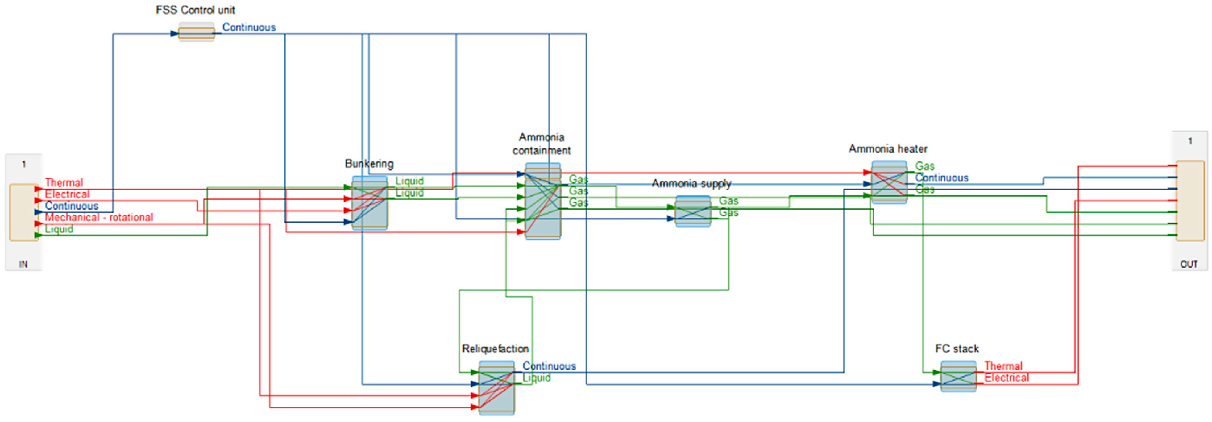
The NH3 fuel supply system described in the previous section was functionally modelled by considering the different subsystems and components. In detail, the systems included were the control unit for the system, the bunkering system, the fuel-cell stack, the NH3 containment system, the NH3 supply system, the reliquefication system, and the NH3 heater. Moreover, as subsystems, the emergency shutdown valves, bunkering pumps, control valves, pressure control valves, storage tank, temperature sensors, compressor, and condenser were modelled. Figure 4 shows the resulting functional model of the system considered, with its boundaries represented by the ‘in’ and ‘out’ blocks.
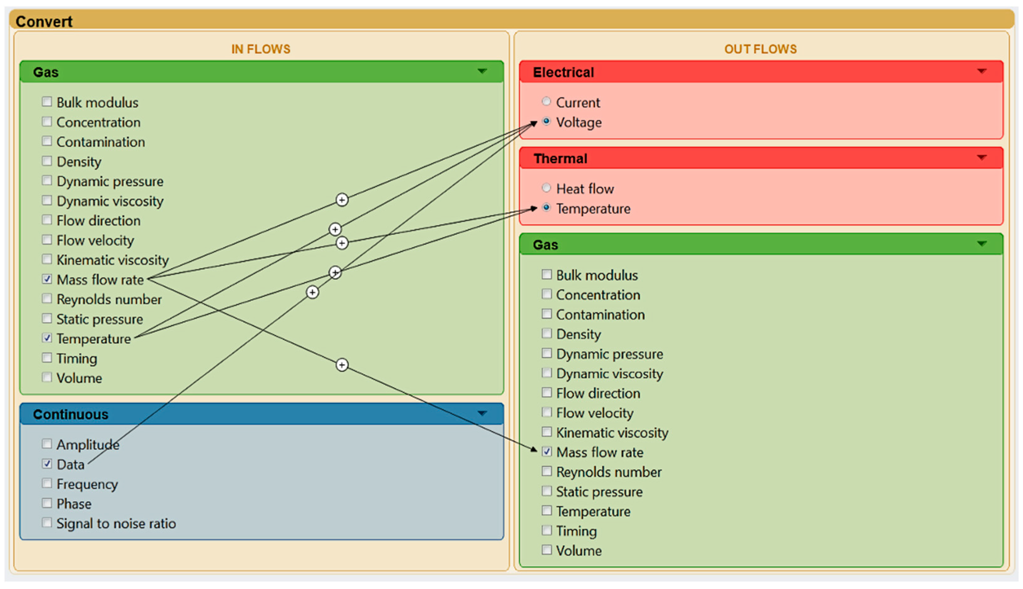
The different systems are modelled as blue boxes and the various components are shown with pale brown. As observed, the various items are organised to represent their functional dependencies. Furthermore, the model shows the distinct inputs and outputs within each item. As seen, the inputs and outputs can take several forms including the transfer of data, energy, and material. To that end, outputs from one subsystem or component must be treated as an input for another element. For instance, the gas static pressure that is the output of the NH3 containment system is used as an input for the NH3 supply system, together with continuous data provided from the system’s controller. Moreover, it should be clarified that the modelling process is based on engineering knowledge, and the final arrangement of flows and components was validated with the equipment manufacturer that participated in the HAZID workshop. Figure 5 shows the function, inflows, and outflows of a fuel-cell module. As seen, the function of the module is to convert the inflow of data (from controller) and gas mass flow rate (from NH3 fuel) to voltage, temperature, and residual NH3.
5.3. System’s Reaction
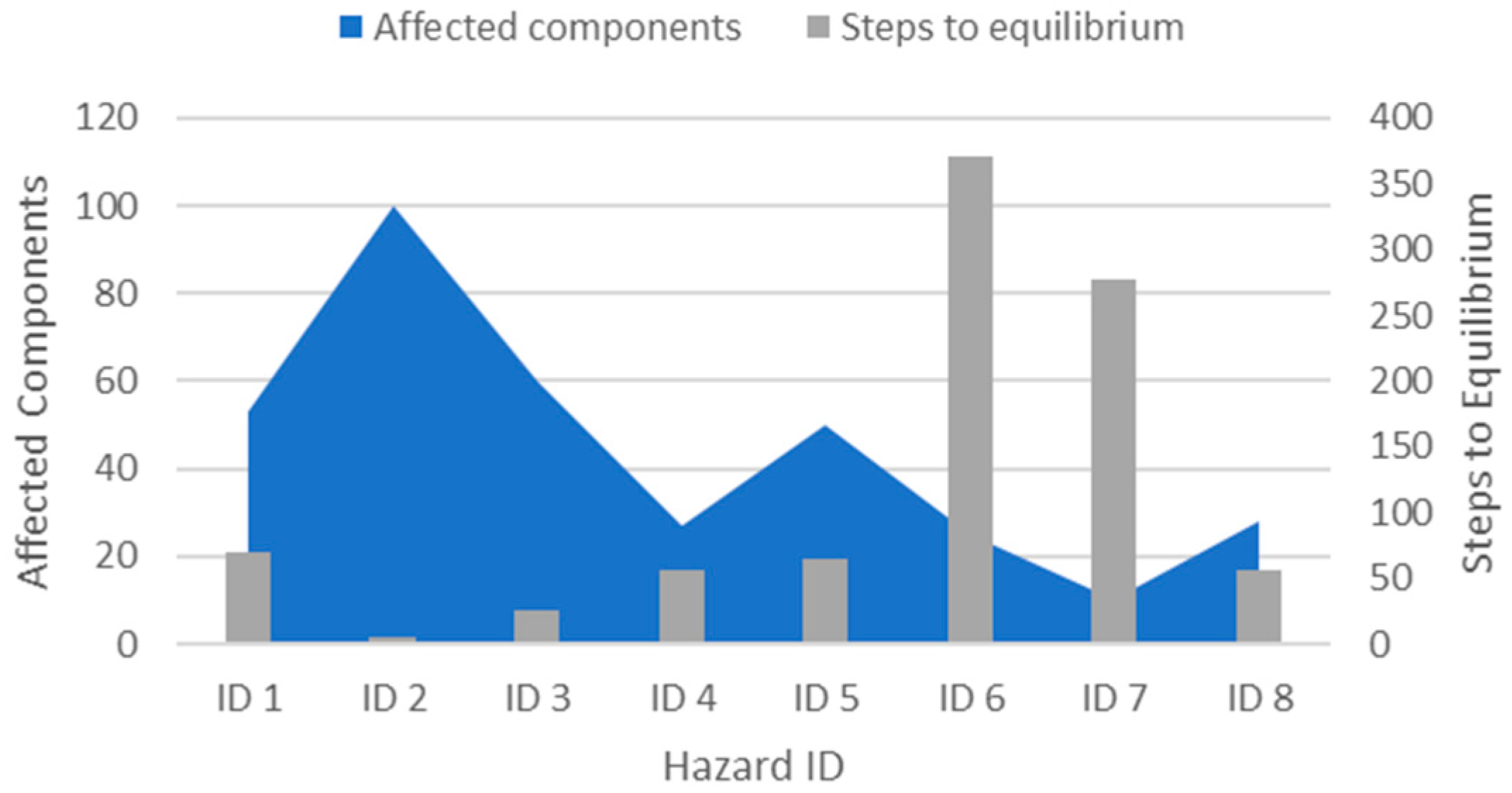
Once the functional-based model was completed, the identified critical hazards (Table 2) were injected sequentially into the system, and the reaction of the system was evaluated through a response simulation. This process was based on FCM, which propagates the presence of a failure downstream of the system [74]. The injection of each hazard was represented by an increase or decrease in the appropriate flow property of the involved item, and the simulation showed the direction of the change of the flow properties of the different modelled items. Figure 6 presents on the horizontal axis the hazards of Table 2, while the vertical axes show the number of affected components by each hazard, together with the number of steps needed for the system to reach equilibrium following the injection of the failure. In other words, the figure examines the intensity of each hazard and how each hazard can affect and destabilise the system. Therefore, the manner in which each hazard propagates through the system can be studied and the severity of each hazard can be gauged, by examining the components it affects and the time required for the system to reach equilibrium. Since the examined system is of relative complexity, identifying components that can be affected by hazards can provide insight into safety improvements. Similarly, examining the time to equilibrium can provide insight into the control of the system, by examining the components it affects and the time required for the system to reach equilibrium. In detail, it was remarked that a failure in the control system (ID 2) would affect the most components (more than 100) in the system; as such, it had the greatest spread. Therefore, the control system can be flagged as critical, and the design of the system can be altered to improve its safety performance. Similarly, a failure in the NH3 tank heater (ID 6) required the most steps until the system reached a state of equilibrium; as such, it destabilised the operation of the system for the longest period. Consequently, it is recommended that additional safeguards (i.e., testing and inspection) are considered to avoid a failure in the control system and the NH3 tank heater.
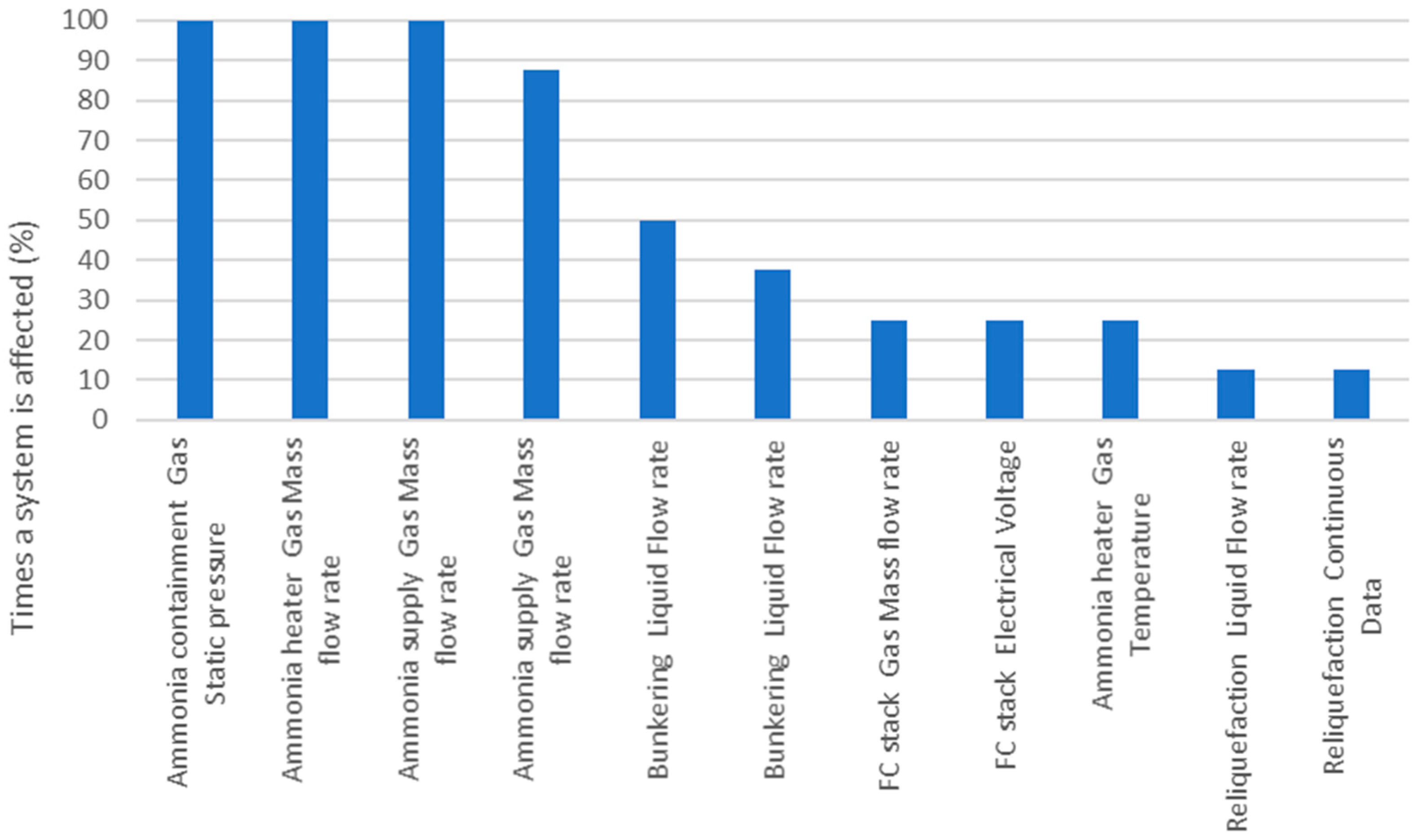
In addition to examining the intensity of each hazard, the sensitivity of each subsystem was studied. In Figure 7, the horizontal axis lists the modelled sub-systems with their flows, and the vertical axis examines the percentage of time that the respective subsystem is affected by one of the injected hazards, thus evaluating the sensitivity of each subsystem. It was observed that both the gas static pressure and the gas mass flow rate from of the NH3 containment system were affected by every injected fault. This means that the NH3 containment system is more sensitive to the considered hazards. As a result, this system was given increased attention in the following phase of the methodology, to further evaluate its effect on safety and reliability.
Examining the effects of the main hazards is a critical step in improving safety by developing mitigating measures. As seen, additional inspection and maintenance on the control system and NH3 tank heater can safeguard against the effects of most of the main hazards. Likewise, examining the sensitivity of the different systems to the hazards can help focus the subsequent steps of the methodology.
5.4. Critical Faults and Components
After identifying the main hazards and examining the reaction of the system to these hazards, the FTA was performed to obtain critical faults according to their reliability metrics. On the basis of the findings of the previous section, the NH3 containment system was given high priority and was modelled on a high level of the fault tree. To enable the methodology to capture critical faults, the FTA examines on the top level the low-voltage output of the entire system, which is subsequently caused by low-voltage output of the entire fuel-cell arrangement. Connected through an OR gate, the next levels examine the failures of the control system, containment system, supply system, and the fuel-cell stack. The lower levels examine the components and respective failures of the subsystems with the appropriate gates used to reflect the fault tolerance of each case. Moreover, the produced fault tree calculates the probability of each fault of the modelled components (), Fussel–Vesely importance measure (), Birnbaum importance measure (), and minimal cut sets (MCS) [97,98].
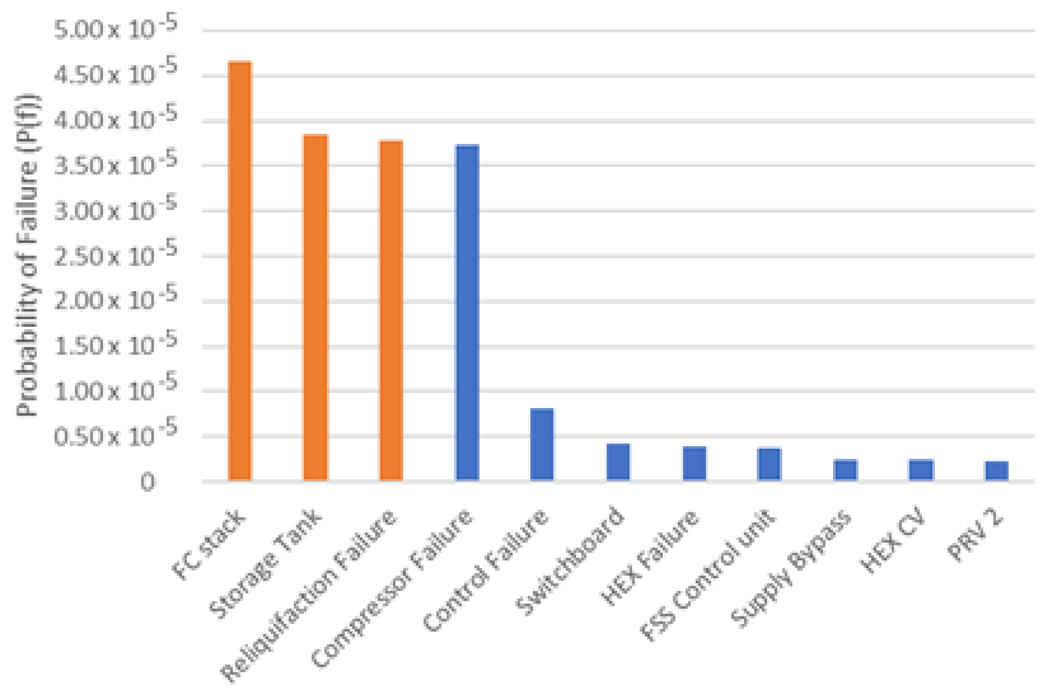
Figure 8 shows the calculated probability of failure from the FTA. It should be noted that the presented probability figures were estimated for the mission profile of the vessel over 1 year of operation. The was calculated for the modelled systems and subsystems, which are represented as intermediate gates. The three subsystems with the highest (highlighted in orange) included the FC stack (), the storage tank (), and the reliquification system (). The impact of these faults needs to be taken into high consideration onboard such a vessel that carries large quantities of ammonia, especially in the FC room; as a result, appropriate measures should be taken. Due to their high , additional operational measures (inspection, maintenance, and testing) are required. Taking into account these results, changes to the design of the system can take place, including the introduction of redundant components, which is outside the scope of this study.
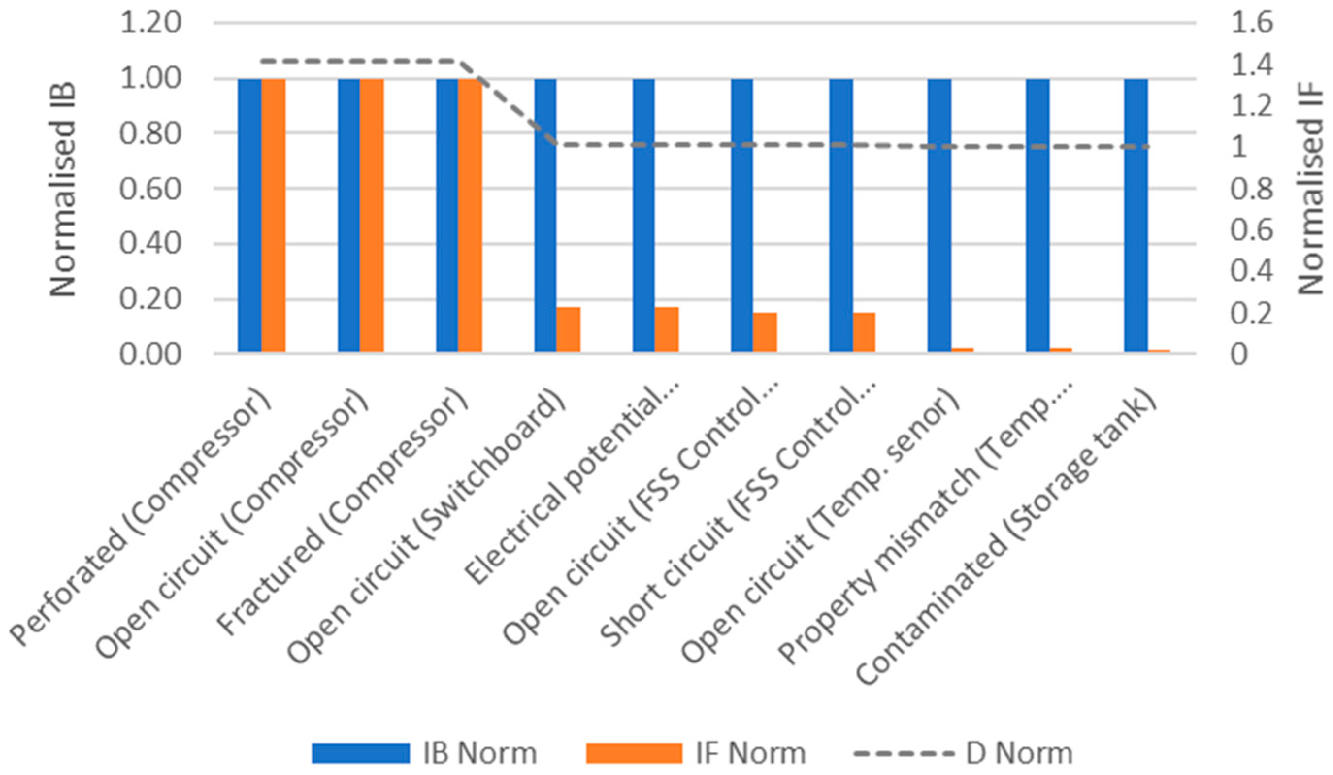
In addition to presenting the probabilities of failures of the subsystems, the severity of the different faults was examined. Figure 9 shows the (left axis) and (right axis) of the different faults, which were modelled as basic events. In addition, these two metrics were combined using the Euclidean distance (left axis) to fully evaluate the different faults. Using the Euclidean distance to combine the two metrics allows for a more accurate assessment of the different faults. As observed, the most critical faults related to the failure of the compressor, which was also flagged as a fault-sensitive subsystem in Figure 8. It should be noted that leakage of ammonia might occur from perforation that can have a severe impact on the crew; thus, identification of hazard zones is required. As with the previous figure, these results can be used to develop operation procedures and to alter the design of the system. In detail, additional inspection can be used with emphasis of detecting signs of perforation and corrosion in the compressor.
5.5. Critical Functional Failure
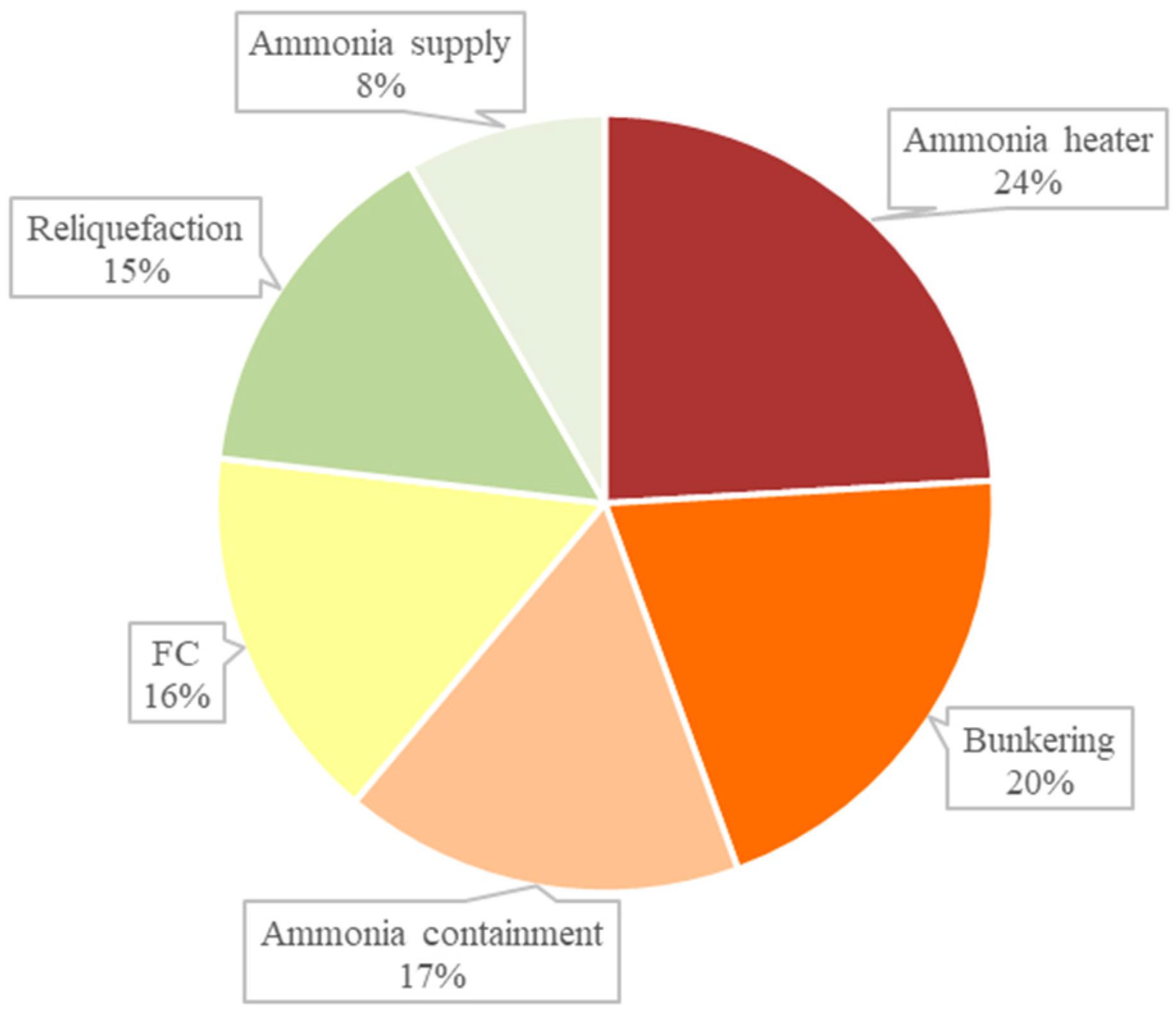
After identifying the critical faults of the system using the FTA, a quantitative analysis was performed to obtain the critical functional failures of the subsystems. The previous analysis suggested that the FC stack, storage tank, and reliquification subsystem have the highest probability of failure. In addition, it was also found that the faults of the compressor are the most critical as they can affect the reliquification system and its components. An FMECA was performed, and the functional failures were categorised according to the ranking adopted in [67]. The derived results with RPN higher than 100, which are considered of moderate to extremely high criticality, can be found in Appendix A. The percentage of critical failures per system is presented in Figure 10, where it is evident that the ammonia heater system was the system with the highest number of functional failures. However, the systems with the most critical functional failures were the FCs and ammonia containment, as can be derived from the extended table in Appendix A. In this section, only the results of high to extremely high criticality (RPN > 250) are presented and discussed in Table 3.
As seen in Table 3, components with the most critical functional failures were the FC module and the switchboard of the FC system, the tank heater in the ammonia containment system, and the compressor in the reliquification system. These results are in agreement with the findings of the previous section, and the aim was to further investigate the failure effects of these components. The most critical functional failures of the system were the low electrical voltage and gas mass flow rate of the FC module, which can be caused by either hydrogen attack or thermal degradation. The former is a result of the potential diffusion of atomic hydrogen that can lead to blistering, embrittlement, or cracking of the FC components. On the other hand, the latter is an outcome of the change in the properties of the FC material due to exposure of the high-heat operation of the FCs. In addition, a functional failure with a lower RPN was the low electrical voltage of the FC module due to dielectric breakdown or of the FC switchboard due to burnout. The former can be caused when the electric field strength surpasses the dielectric strength of an insulator material, whereas burnout is a result of material degradation occurring during long-term aging and leading to an increased, localised power density dissipation. On the other hand, the low temperature of the tank heater is a critical functional failure caused by material burnout. Similar causes can lead to a low gas mass flow rate or static pressure of the compressor.
6. Conclusions
The decarbonisation of shipping has attracted great attention, leading to the introduction of novel configurations and alternative zero-carbon emissions fuels. Nonetheless, prior to the commercialisation and acceptance of these systems, it is incremental to prove that they are at least as safe as the traditional systems. Therefore, a safety and risk assessment of the new technologies and fuels is crucial to support the endorsement of the new system.
In this work, a novel ammonia-powered fuel-cell system is proposed, which can play a significant role in shipping decarbonisation. As a result, a holistic safety, reliability, and operability methodology was developed and applied to the proposed system. A HAZID analysis was performed with participants from both academia and industry for identifying the main hazards, whereas relevant safeguards were proposed. Ammonia leak inside the fuel cell was identified as one of the most critical hazards, which is attributed to the fuel characteristics and can have severe impacts on the other systems. Furthermore, the examined system was depicted in a functional model, allowing further safety and reliability analysis. The operability of the system was evaluated, and it was derived that the failure of the control system can affect the most components, whereas the failure of the ammonia tank heater can destabilise the operation of the system for longer intervals. As a result, further safety operational procedures can be adopted, such as testing and inspection of the control system in order to avoid failures. Furthermore, an FTA was performed to obtain critical components and faults according to their reliability. The results indicated that the switchboard, the controller of the system, the tank heater, the reliquification compressor, and the fuel cells are amongst the most critical components regarding failure and reliability. Finally, an FMECA study was performed, and the functional failures of the systems were ranked according to their criticality, with fuel cells being among the components with the most critical functional failures. Consequently, risk control options including operating practices and design modifications should address these components.
It was derived from the analysis that one of the main challenges in introducing a novel system with ammonia onboard is to limit the potential of exposure of crew to ammonia, due to the toxicity of the fuel. Potential safeguards were discussed in this work, such as placing the bunkering station in a safe location and enabling the crew to remotely oversee the procedure. Another measure is sufficient ventilation and the placement of outlets in areas, where there is low risk of subjecting the crew to ammonia exposure. The need for an identification of hazardous zones was also highlighted. Lastly, it is expected that the crew will be equipped with special attire in order to minimise the risk of potential exposure. At a future stage, the dispersion of potential leakages and the impact they can have on the ship, crew, and marine environment need to be investigated. This is a step that requires dedicated analysis and is significant for the introduction of a novel system with a toxic fuel, such as the one described herein.
In future work, the modelling of the system could be expanded including more detailed analysis of the components, when the system is more mature and relevant information is available. Furthermore, the reliability data found in OREDA are not derived specifically for ammonia; thus, the rates considered should be updated in future work when more specific data are found.
These outcomes shed initial light on the design and operating hazards of the proposed novel ammonia-powered fuel-cell system. This study is vital to understand the new risks and safety requirements created by the introduction of a novel fuel and, thus, can provide support to both technological and policy framework development.
Author Contributions
Conceptualization, N.L.T., M.C. and E.B.; Formal analysis, N.L.T. and M.C.; Funding acquisition, E.B.; Methodology, N.L.T. and M.C.; Supervision, E.B. and G.T.; Visualization, N.L.T. and M.C.; Writing—original draft, N.L.T. and M.C.; Writing—review & editing, N.L.T., M.C., E.B. and G.T. All authors have read and agreed to the published version of the manuscript.
Funding
This research was partially funded by the European Union’s Horizon 2020 research and innovation programme under grant agreement No. 875156.
Institutional Review Board Statement
Not applicable.
Informed Consent Statement
Not applicable.
Acknowledgments
This work was partially supported by the “ShipFC” project that was funded by the European Union’s Horizon 2020 research and innovation programme under grant agreement No. 875156. The authors greatly acknowledge the funding from the DNV and Royal Caribbean Group for the MSRC establishment and operation. The opinions expressed herein are those of the authors and should not be construed to reflect the views of EU, DNV and RCG.
Conflicts of Interest
The authors declare no conflict of interest.
Appendix A
Table A1.
FMECA analysis of the ammonia-powered fuel-cell system with 100 < RPN ≤ 150 considered moderate, 150 < RPN ≤ 250 considered moderately high, and 250 < RPN ≤ 350 considered high.
Table A1.
FMECA analysis of the ammonia-powered fuel-cell system with 100 < RPN ≤ 150 considered moderate, 150 < RPN ≤ 250 considered moderately high, and 250 < RPN ≤ 350 considered high.
| ID | Subsystem/Component | Failure Mode | Causes of Failure | O | S | D | RPN |
|---|---|---|---|---|---|---|---|
| FM1 | FC | Electrical voltage low | Hydrogen attack | 4.0 | 10.0 | 8.0 | 320 |
| FM2 | FC | Electrical voltage low | Thermal degradation | 4.0 | 10.0 | 8.0 | 320 |
| FM3 | FC | Gas mass flow rate low | Hydrogen attack | 4.0 | 10.0 | 8.0 | 320 |
| FM4 | FC | Gas mass flow rate low | Thermal degradation | 4.0 | 10.0 | 8.0 | 320 |
| FM5 | Heater | Thermal temperature low | Burnout | 4.0 | 10.0 | 7.0 | 280 |
| FM6 | FC | Electrical voltage low | Dielectric breakdown | 4.0 | 10.0 | 7.0 | 280 |
| FM7 | Switchboard | Electrical voltage low | Burnout | 4.0 | 10.0 | 7.0 | 280 |
| FM8 | Compressor | Gas mass flow rate low | Burnout | 4.0 | 10.0 | 7.0 | 280 |
| FM9 | Compressor | Gas static pressure low | Burnout | 4.0 | 10.0 | 7.0 | 280 |
| FM10 | FC | Electrical voltage low | Temperature induced deformation | 4.0 | 10.0 | 6.0 | 240 |
| FM11 | FC | Gas mass flow rate low | Temperature induced deformation | 4.0 | 10.0 | 6.0 | 240 |
| FM12 | Storage tank | Gas static pressure low | Corrosive attack | 4.0 | 10.0 | 6.0 | 240 |
| FM13 | ESD | Gas mass flow rate low | Bending deformation | 3.0 | 10.0 | 8.0 | 240 |
| FM14 | Bunkering ESD | Gas static pressure low | Bending deformation | 3.0 | 10.0 | 8.0 | 240 |
| FM15 | Bunkering ESD | Liquid flow rate low | Bending deformation | 3.0 | 10.0 | 8.0 | 240 |
| FM16 | ESD | Gas mass flow rate low | Abrasive wear | 3.0 | 10.0 | 7.0 | 210 |
| FM17 | Bunkering ESD | Gas static pressure low | Abrasive wear | 3.0 | 10.0 | 7.0 | 210 |
| FM18 | Bunkering ESD | Liquid flow rate low | Abrasive wear | 3.0 | 10.0 | 7.0 | 210 |
| FM19 | Afterburner | Thermal temperature low | Burnout | 3.0 | 10.0 | 7.0 | 210 |
| FM20 | Compressor | Gas mass flow rate low | Burnout | 3.0 | 10.0 | 7.0 | 210 |
| FM21 | Compressor | Gas static pressure low | Burnout | 3.0 | 10.0 | 7.0 | 210 |
| FM22 | FC | Gas mass flow rate low | Dielectric breakdown | 4.0 | 10.0 | 5.0 | 200 |
| FM23 | Compressor | Gas mass flow rate low | Abrasive wear | 4.0 | 10.0 | 5.0 | 200 |
| FM24 | Compressor | Gas static pressure low | Abrasive wear | 4.0 | 10.0 | 5.0 | 200 |
| FM25 | Ammonia HEX | Mixture gas-liquid mass flow rate low | Heat loss | 3.0 | 10.0 | 6.0 | 180 |
| FM26 | Ammonia HEX | Mixture gas-liquid static pressure low | Heat loss | 3.0 | 10.0 | 6.0 | 180 |
| FM27 | Ammonia HEX | Mixture gas-liquid temperature low | Heat loss | 3.0 | 10.0 | 6.0 | 180 |
| FM28 | Heat exchanger | Gas mass flow rate low | Heat loss | 3.0 | 10.0 | 6.0 | 180 |
| FM29 | Heat exchanger | Gas static pressure low | Heat loss | 3.0 | 10.0 | 6.0 | 180 |
| FM30 | Heat exchanger | Gas temperature low | Heat loss | 3.0 | 10.0 | 6.0 | 180 |
| FM31 | FC | Electrical voltage low | Corrosive attack | 4.0 | 10.0 | 4.0 | 160 |
| FM32 | Storage control valve | Gas mass flow rate low | Bending deformation | 2.0 | 10.0 | 8.0 | 160 |
| FM33 | Storage control valve | Gas mass flow rate low | Solidification | 2.0 | 10.0 | 8.0 | 160 |
| FM34 | Heater control valve | Gas mass flow rate low | Bending deformation | 2.0 | 10.0 | 8.0 | 160 |
| FM35 | Heater control valve | Gas temperature low | Bending deformation | 2.0 | 10.0 | 8.0 | 160 |
| FM36 | Pressure relief valve | Gas mass flow rate low | Bending deformation | 2.0 | 10.0 | 8.0 | 160 |
| FM37 | Pressure relief valve | Gas mass flow rate low | Solidification | 2.0 | 10.0 | 8.0 | 160 |
| FM38 | Pressure relief valve | Gas static pressure low | Solidification | 2.0 | 10.0 | 8.0 | 160 |
| FM39 | Pressure relief valve | Gas static pressure low | Bending deformation | 2.0 | 10.0 | 8.0 | 160 |
| FM40 | Bypass control valve | Gas mass flow rate low | Bending deformation | 2.0 | 10.0 | 8.0 | 160 |
| FM41 | Bunkering control valve | Liquid flow rate low | Bending deformation | 2.0 | 10.0 | 8.0 | 160 |
| FM42 | Bunkering vapour return | Gas static pressure low | Bending deformation | 2.0 | 10.0 | 8.0 | 160 |
| FM43 | Reliq. control valve | Gas mass flow rate low | Bending deformation | 2.0 | 10.0 | 8.0 | 160 |
| FM44 | Storage tank | Gas static pressure low | Impact wear | 3.0 | 10.0 | 5.0 | 150 |
| FM45 | Controller | Signal continuous amplitude low | Dielectric breakdown | 3.0 | 10.0 | 5.0 | 150 |
| FM46 | Controller | Signal continuous amplitude low | Burnout | 3.0 | 10.0 | 5.0 | 150 |
| FM47 | ESD | Gas mass flow rate low | Dielectric breakdown | 3.0 | 10.0 | 5.0 | 150 |
| FM48 | ESD | Gas mass flow rate low | Burnout | 3.0 | 10.0 | 5.0 | 150 |
| FM49 | ESD | Gas mass flow rate low | Silting | 3.0 | 10.0 | 5.0 | 150 |
| FM50 | Bunkering ESD | Gas static pressure low | Silting | 3.0 | 10.0 | 5.0 | 150 |
| FM51 | Bunkering ESD | Gas static pressure low | Dielectric breakdown | 3.0 | 10.0 | 5.0 | 150 |
| FM52 | Bunkering ESD | Gas static pressure low | Burnout | 3.0 | 10.0 | 5.0 | 150 |
| FM53 | Bunkering ESD | Liquid flow rate low | Silting | 3.0 | 10.0 | 5.0 | 150 |
| FM54 | Bunkering ESD | Liquid flow rate low | Dielectric breakdown | 3.0 | 10.0 | 5.0 | 150 |
| FM55 | Bunkering ESD | Liquid flow rate low | Burnout | 3.0 | 10.0 | 5.0 | 150 |
| FM56 | Bunkering ESD | Liquid flow rate low | Dielectric breakdown | 3.0 | 10.0 | 5.0 | 150 |
| FM57 | Bunkering connection | Liquid flow rate low | Abrasive wear | 3.0 | 10.0 | 5.0 | 150 |
| FM58 | bunkering pump | Liquid flow rate low | Abrasive wear | 3.0 | 10.0 | 5.0 | 150 |
| FM59 | FSS control unit | Continuous data low | Burnout | 3.0 | 10.0 | 5.0 | 150 |
| FM60 | FSS control unit | Continuous data low | Dielectric breakdown | 3.0 | 10.0 | 5.0 | 150 |
| FM61 | Condenser | Liquid flow rate low | Abrasive wear | 3.0 | 10.0 | 5.0 | 150 |
| FM62 | Condenser | Liquid temperature low | Abrasive wear | 3.0 | 10.0 | 5.0 | 150 |
| FM63 | Storage control valve | Gas mass flow rate low | Abrasive wear | 2.0 | 10.0 | 7.0 | 140 |
| FM64 | Pressure relief valve | Gas mass flow rate low | Abrasive wear | 2.0 | 10.0 | 7.0 | 140 |
| FM65 | Pressure relief valve | Gas static pressure low | Abrasive wear | 2.0 | 10.0 | 7.0 | 140 |
| FM66 | Temp senor | Continuous data low | Burnout | 2.0 | 10.0 | 7.0 | 140 |
| FM67 | Temp. sensor | Continuous data low | Dielectric breakdown | 2.0 | 10.0 | 7.0 | 140 |
| FM68 | Temp. sensor | Continuous data low | Burnout | 2.0 | 10.0 | 7.0 | 140 |
| FM69 | FC | Electrical voltage low | Thermal fatigue | 4.0 | 10.0 | 3.0 | 120 |
| FM70 | FC | Gas mass flow rate low | Corrosive attack | 4.0 | 10.0 | 3.0 | 120 |
| FM71 | FC | Gas mass flow rate low | Thermal fatigue | 4.0 | 10.0 | 3.0 | 120 |
| FM72 | Heater | Thermal temperature low | Thermal fatigue | 4.0 | 10.0 | 3.0 | 120 |
| FM73 | Bunkering connection | Liquid flow rate low | Corrosive attack | 3.0 | 10.0 | 4.0 | 120 |
| FM74 | Afterburner | Thermal temperature low | Corrosive attack | 3.0 | 10.0 | 4.0 | 120 |
| FM75 | Compressor | Gas mass flow rate low | Brittle fracture | 4.0 | 10.0 | 3.0 | 120 |
| FM76 | Compressor | Gas static pressure low | Brittle fracture | 4.0 | 10.0 | 3.0 | 120 |
| FM77 | Condenser | Liquid flow rate low | Corrosive attack | 3.0 | 10.0 | 4.0 | 120 |
| FM78 | Condenser | Liquid temperature low | Corrosive attack | 3.0 | 10.0 | 4.0 | 120 |
| FM79 | Ammonia HEX | Mixture gas–liquid mass flow rate low | Corrosive fatigue | 2.0 | 10.0 | 5.0 | 100 |
| FM80 | Ammonia HEX | Mixture gas–liquid static pressure low | Corrosive fatigue | 2.0 | 10.0 | 5.0 | 100 |
| FM81 | Ammonia HEX | Mixture gas–liquid temperature low | Corrosive fatigue | 2.0 | 10.0 | 5.0 | 100 |
| FM82 | Storage control valve | Gas mass flow rate low | Dielectric breakdown | 2.0 | 10.0 | 5.0 | 100 |
| FM83 | Storage control valve | Gas mass flow rate low | Burnout | 2.0 | 10.0 | 5.0 | 100 |
| FM84 | Storage control valve | Gas mass flow rate low | Silting | 2.0 | 10.0 | 5.0 | 100 |
| FM85 | Heat exchanger | Gas mass flow rate low | Corrosive fatigue | 2.0 | 10.0 | 5.0 | 100 |
| FM86 | Heat exchanger | Gas static pressure low | Corrosive fatigue | 2.0 | 10.0 | 5.0 | 100 |
| FM87 | Heat exchanger | Gas temperature low | Corrosive fatigue | 2.0 | 10.0 | 5.0 | 100 |
| FM88 | Heater control valve | Gas mass flow rate low | Dielectric breakdown | 2.0 | 10.0 | 5.0 | 100 |
| FM89 | Heater control valve | Gas mass flow rate low | Burnout | 2.0 | 10.0 | 5.0 | 100 |
| FM90 | Heater control valve | Gas mass flow rate low | Silting | 2.0 | 10.0 | 5.0 | 100 |
| FM91 | Heater control valve | Gas temperature low | Burnout | 2.0 | 10.0 | 5.0 | 100 |
| FM92 | Heater control valve | Gas temperature low | Dielectric breakdown | 2.0 | 10.0 | 5.0 | 100 |
| FM93 | Heater control valve | Gas temperature low | Silting | 2.0 | 10.0 | 5.0 | 100 |
| FM94 | Pressure relief valve | Gas mass flow rate low | Silting | 2.0 | 10.0 | 5.0 | 100 |
| FM95 | Pressure relief valve | Gas static pressure low | Silting | 2.0 | 10.0 | 5.0 | 100 |
| FM96 | Temp senor | Continuous data low | Dielectric breakdown | 2.0 | 10.0 | 5.0 | 100 |
| FM97 | Bypass control valve | Gas mass flow rate low | Dielectric breakdown | 2.0 | 10.0 | 5.0 | 100 |
| FM98 | Bypass control valve | Gas mass flow rate low | Burnout | 2.0 | 10.0 | 5.0 | 100 |
| FM99 | Bypass control valve | Gas mass flow rate low | Silting | 2.0 | 10.0 | 5.0 | 100 |
| FM100 | Bunkering control valve | Liquid flow rate low | Burnout | 2.0 | 10.0 | 5.0 | 100 |
| FM101 | Bunkering control valve | Liquid flow rate low | Dielectric breakdown | 2.0 | 10.0 | 5.0 | 100 |
| FM102 | Bunkering control valve | Liquid flow rate low | Silting | 2.0 | 10.0 | 5.0 | 100 |
| FM103 | Bunkering vapour return | Gas static pressure low | Dielectric breakdown | 2.0 | 10.0 | 5.0 | 100 |
| FM104 | Bunkering vapour return | Gas static pressure low | Burnout | 2.0 | 10.0 | 5.0 | 100 |
| FM105 | Bunkering vapour return | Gas static pressure low | Silting | 2.0 | 10.0 | 5.0 | 100 |
| FM106 | Reliq. control valve | Gas mass flow rate low | Dielectric breakdown | 2.0 | 10.0 | 5.0 | 100 |
| FM107 | Reliq. control valve | Gas mass flow rate low | Burnout | 2.0 | 10.0 | 5.0 | 100 |
| FM108 | Reliq. control valve | Gas mass flow rate low | Silting | 2.0 | 10.0 | 5.0 | 100 |
Colour code: Red: High importance, Orange: moderate high, Yellow: moderate.
References
- Olivier, J.G.J.; Peters, J.A.H.W. Trends in Global CO2 and Total Greenhouse Gas Emissions; PBL Netherlands Environmental Assessment Agency: The Hague, The Netherlands, 2020. [Google Scholar]
- UNFCCC. Adoption of the Paris Agreement; UNFCCC: New York, NY, USA, 2016.
- IEA. World Energy Outlook 2017; IEA: Paris, France, 2017.
- UNCTAD. Review of Maritime Transport, Technical Report; UNCTAD: Geneva, Switzerland, 2017; ISBN 9789211129229. [Google Scholar]
- MEPC. Reduction of GHG Emissions from Ships. Fourth IMO GHG Study 2020; MEPC: Oxford, UK, 2020; Volume 53.
- IMO. Reducing Greenhouse Gas Emissions from Ships; IMO: London, UK, 2020. [Google Scholar]
- Ren, J.; Liang, H. Measuring the sustainability of marine fuels: A fuzzy group multi-criteria decision making approach. Transp. Res. Part D Transp. Environ. 2017, 54, 12–29. [Google Scholar] [CrossRef]
- Deniz, C.; Zincir, B. Environmental and economical assessment of alternative marine fuels. J. Clean. Prod. 2016, 113, 438–449. [Google Scholar] [CrossRef]
- Brynolf, S.; Fridell, E.; Andersson, K. Environmental assessment of marine fuels: Liquefied natural gas, liquefied biogas, methanol and bio-methanol. J. Clean. Prod. 2014, 74, 86–95. [Google Scholar] [CrossRef]
- Andersson, K.; Márquez Salazar, M. Methanol as a Marine Fuel; FCBI Energy: London, UK, 2015; 46p. [Google Scholar]
- Brynolf, S.; Baldi, F.; Johnson, H. Energy Efficiency and Fuel Changes to Reduce Environmental Impacts. In Shipping and the Environment: Improving Environmental Performance in Marine Transportation; Andersson, K., Brynolf, S., Lindgren, J.F., Wilewska-Bien, M., Eds.; Springer: Berlin/Heidelberg, Germany, 2016; pp. 295–339. ISBN 978-3-662-49045-7. [Google Scholar]
- Trivyza, N.L.; Rentizelas, A.; Theotokatos, G. A novel multi-objective decision support method for ship energy systems synthesis to enhance sustainability. Energy Convers. Manag. 2018, 168, 128–149. [Google Scholar] [CrossRef] [Green Version]
- Horvath, S.; Fasihi, M.; Breyer, C. Techno-economic analysis of a decarbonized shipping sector: Technology suggestions for a fleet in 2030 and 2040. Energy Convers. Manag. 2018, 164, 230–241. [Google Scholar] [CrossRef]
- Jeong, J.; Seo, S.; You, H.; Chang, D. Comparative analysis of a hybrid propulsion using LNG-LH2complying with regulations on emissions. Int. J. Hydrogen Energy 2018, 43, 3809–3821. [Google Scholar] [CrossRef]
- Chen, H.; Zhang, Z.; Guan, C.; Gao, H. Optimization of sizing and frequency control in battery/supercapacitor hybrid energy storage system for fuel cell ship. Energy 2020, 197, 117285. [Google Scholar] [CrossRef]
- Jianyun, Z.; Li, C.; Bin, W.; Lijuan, X. Optimal design of a hybrid electric propulsive system for an anchor handling tug supply vessel. Appl. Energy 2018, 226, 423–436. [Google Scholar] [CrossRef]
- Cheliotis, M.; Boulougouris, E.; Trivyza, N.L.; Theotokatos, G.; Livanos, G.; Mantalos, G.; Stubos, A.; Stamatakis, E.; Venetsanos, A. Review on the Safe Use of Ammonia Fuel Cells in the Maritime Industry. Energies 2021, 14, 3023. [Google Scholar] [CrossRef]
- Hagen, A.; Langnickel, H.; Sun, X. Operation of solid oxide fuel cells with alternative hydrogen carriers. Int. J. Hydrogen Energy 2019, 44, 18382–18392. [Google Scholar] [CrossRef]
- Siddiqui, O.; Ishaq, H.; Dincer, I. Experimental investigation of improvement capability of ammonia fuel cell performance with addition of hydrogen. Energy Convers. Manag. 2020, 205, 112372. [Google Scholar] [CrossRef]
- Baldi, F.; Azzi, A.; Maréchal, F. From renewable energy to ship fuel: Ammonia as an energy vector and mean for energy storage. Comput. Aided Chem. Eng. 2019, 46, 1747–1752. [Google Scholar] [CrossRef]
- De Vries, N. Ammonia as a Marine Fuel: Safety. In Proceedings of the Ammonia Energy Conference, Orlando, FL, USA, 12–14 November 2019. [Google Scholar]
- Tofalos, C.; Jeong, B.; Jang, H. Safety comparison analysis between LNG/LH 2 for bunkering operation. J. Int. Marit. Saf. Environ. Aff. Shipp. 2020, 4, 135–150. [Google Scholar] [CrossRef]
- Aarskog, F.G.; Hansen, O.R.; Strømgren, T.; Ulleberg, Ø. Concept risk assessment of a hydrogen driven high speed passenger ferry. Int. J. Hydrogen Energy 2020, 45, 1359–1372. [Google Scholar] [CrossRef]
- Shakeri, N.; Zadeh, M.; Bremnes Nielsen, J. Hydrogen Fuel Cells for Ship Electric Propulsion: Moving Toward Greener Ships. IEEE Electrif. Mag. 2020, 8, 27–43. [Google Scholar] [CrossRef]
- Uwemedimo, E.; Doymus, M.; Eylul, D. Understanding Regulations, Sustainable Shipping, Alternative Marine Fuels and LNG. In Proceedings of the 8th Global LNG Bunkering Summit 2020, Amsterdam, The Netherlands, 28–30 January 2020. [Google Scholar]
- Gray, N.; McDonagh, S.; O’Shea, R.; Smyth, B.; Murphy, J.D. Decarbonising ships, planes and trucks: An analysis of suitable low-carbon fuels for the maritime, aviation and haulage sectors. Adv. Appl. Energy 2021, 1, 100008. [Google Scholar] [CrossRef]
- Moller, A. Alcohol, Biomethane and Ammonia Are the Best-Positioned Fuels to Reach Zero Net Emissions. Available online: https://www.maersk.com/news/articles/2019/10/24/alcohol-biomethane-and-ammonia-are-the-best-positioned-fuels-to-reach-zero-net-emissions (accessed on 5 May 2021).
- Fasihi, M.; Weiss, R.; Savolainen, J.; Breyer, C. Global potential of green ammonia based on hybrid PV-wind power plants. Appl. Energy 2021, 294, 116170. [Google Scholar] [CrossRef]
- Cluster, O.H. Hydrogen and Ammonia Infrastructure Safety and Risk Information and Guidance; Lloyd’s Register: London, UK, 2020. [Google Scholar]
- Hansson, J.; Brynolf, S.; Fridell, E.; Lehtveer, M. The potential role of ammonia as marine fuel-based on energy systems modeling and multi-criteria decision analysis. Sustainability 2020, 12, 3265. [Google Scholar] [CrossRef] [Green Version]
- Tansport & Environment. Roadmap to Decarbonising European Shipping; Tansport & Environment: Brussels, Belgium, 2018. [Google Scholar]
- Damo, U.M.; Ferrari, M.L.; Turan, A.; Massardo, A.F. Solid oxide fuel cell hybrid system: A detailed review of an environmentally clean and efficient source of energy. Energy 2019, 168, 235–246. [Google Scholar] [CrossRef] [Green Version]
- Jeerh, G.; Zhang, M.; Tao, S. Recent progress in ammonia fuel cells and their potential applications. J. Mater. Chem. A 2021. [Google Scholar] [CrossRef]
- ShipFC. Grant Agreement Number: 875156—ShipFC; European Union: Maastricht, The Netherlands, 2019. [Google Scholar]
- Parkinson, B.; Balcombe, P.; Speirs, J.F.; Hawkes, A.D.; Hellgardt, K. Levelized cost of CO2 mitigation from hydrogen production routes. Energy Environ. Sci. 2019, 12, 19–40. [Google Scholar] [CrossRef]
- Chang, D.; Rhee, T.; Nam, K.; Chang, K.; Lee, D.; Jeong, S. A study on availability and safety of new propulsion systems for LNG carriers. Reliab. Eng. Syst. Saf. 2008, 93, 1877–1885. [Google Scholar] [CrossRef]
- DNV GL. Assessment of Selected Ternative Fuels and technologies. Imo 2018, 391, 1–48. [Google Scholar]
- de Haag, P.U.; Ale, B. Guidelines for Quantitative Risk Assessment (Purple Book). Guidelines for Quantitative Risk Assessment; General for Social Affairs and Employment: The Hague, The Netherlands, 1999; pp. 4–237. [Google Scholar]
- Inal, O.B.; Deniz, C. Assessment of fuel cell types for ships: Based on multi-criteria decision analysis. J. Clean. Prod. 2020, 265, 121734. [Google Scholar] [CrossRef]
- Vidmar, P.; Perkovič, M. Safety assessment of crude oil tankers. Saf. Sci. 2018, 105, 178–191. [Google Scholar] [CrossRef]
- Di Bona, G.; Forcina, A.; Falcone, D.; Silvestri, L. Critical risks method (CRM): A new safety allocation approach for a critical infrastructure. Sustainability 2020, 12, 4949. [Google Scholar] [CrossRef]
- Kristiansen, S. Maritime Transportation Safety Management and Risk Analysis; Elsevier Butterworth-Heinemann: Oxford, UK, 2005; ISBN 10:0750659998. [Google Scholar]
- Dester, W.S.; Blockley, D.I. Hazard engineering. Struct. Saf. 1994, 16, 3–12. [Google Scholar] [CrossRef]
- Pasman, H.J.; Rogers, W.J.; Mannan, M.S. How can we improve process hazard identification? What can accident investigation methods contribute and what other recent developments? A brief historical survey and a sketch of how to advance. J. Loss Prev. Process Ind. 2018, 55, 80–106. [Google Scholar] [CrossRef]
- Wang, Y.; Gu, Y.; Zhang, H.; Yang, J.; Wang, J.; Guan, W.; Chen, J.; Chi, B.; Jia, L.; Muroyama, H.; et al. Efficient and durable ammonia power generation by symmetric flat-tube solid oxide fuel cells. Appl. Energy 2020, 270, 115185. [Google Scholar] [CrossRef]
- American Bureau of Shipping (ABS). Ammonia as Marine Fuel. Sustain. Whitepaper; American Bureau of Shipping: Houston, TX, USA, 2020. [Google Scholar]
- Vista Oil and Gas. Hazard Identification (Hazid) Studies. 2019. Available online: https://www3.opic.gov/Environment/EIA/vistaaleph/ESIA/Chapter_10/Chapter_10_Annex.pdf (accessed on 20 February 2021).
- Mobley, K.; Higgins, L.; Wikoff, D. Maintenance Engineering Handbook, 7th ed.; Mobley, R.K., Ed.; McGraw Hill: New York, NY, USA, 2008; ISBN 0071641017. [Google Scholar]
- Ruijters, E.; Stoelinga, M. Fault tree analysis: A survey of the state-of-the-art in modeling, analysis and tools. Comput. Sci. Rev. 2015, 15, 29–62. [Google Scholar] [CrossRef] [Green Version]
- Henriques de Gusmão, A.P.; Mendonça Silva, M.; Poleto, T.; Camara e Silva, L.; Cabral Seixas Costa, A.P. Cybersecurity risk analysis model using fault tree analysis and fuzzy decision theory. Int. J. Inf. Manag. 2018, 43, 248–260. [Google Scholar] [CrossRef]
- Bolbot, V.; Theotokatos, G.; Bujorianu, L.M.; Boulougouris, E.; Vassalos, D. Vulnerabilities and safety assurance methods in Cyber-Physical Systems: A comprehensive review. Reliab. Eng. Syst. Saf. 2019, 182, 179–193. [Google Scholar] [CrossRef] [Green Version]
- Tixier, J.; Dusserre, G.; Salvi, O.; Gaston, D. Review of 62 risk analysis methodologies of industrial plants. J. Loss Prev. Process Ind. 2002, 15, 291–303. [Google Scholar] [CrossRef] [Green Version]
- Kim, K.; Kang, H.; Kim, Y. Risk assessment for natural gas hydrate carriers: A hazard identification (HAZID) study. Energies 2015, 8, 3142–3164. [Google Scholar] [CrossRef] [Green Version]
- Etemad, H.; Choi, J.-H. Hazard identification (HAZID) of LNG dual-fueled ships operating between the Korean port of Busan and the Iranian port of Bandar Abbas. DBPIA 2017, 473–488. [Google Scholar] [CrossRef]
- IMO. FSA—Liquefied Natural Gas (LNG) Carriers; IMO: London, UK, 2007. [Google Scholar]
- Fu, S.; Yan, X.; Zhang, D.; Li, C.; Zio, E. Framework for the quantitative assessment of the risk of leakage from LNG-fueled vessels by an event tree-CFD. J. Loss Prev. Process Ind. 2016, 43, 42–52. [Google Scholar] [CrossRef] [Green Version]
- Zhan, Y.; Xu, F.; Zhang, Y. The application of HAZOP analysis on risk assessment of the 10000TEU container ships. In Proceedings of the International Asia Symposium on Intelligent Interaction and Affective Computing, ASIA 2009, Wuhan, China, 8–9 December 2009; pp. 59–62. [Google Scholar]
- Gil, Y.; Yoo, S.; Kim, Y.; Oh, J.; Byun, Y.; Woo, I.; Kim, J.; Choi, S. Concept Design and Risk Assessment of Nuclear Propulsion Ship. In Proceedings of the Transactions of the Korean Nuclear Society Spring Meeting, Jeju, Korea, 29–30 May 2014; pp. 29–31. [Google Scholar]
- Joung, T.; Kim, H.; Kim, Y.; Cho, S.; Kang, K.; Liu, Y.; Lundteigen, M.A. Hazard identification for a dynamic positioning and mooring system in arctic condition: Complementary use of hazard identification study (HAZID) and Systems Theoretic Process Analysis (STPA). In Safety and Reliability—Safe Societies in a Changing World, Proceedings of the 28th International European Safety and Reliability Conference, ESREL 2018, Trondheim, Norway, 17–21 June 2018; CRC Press: Boca Raton, FL, USA, 2018; pp. 1735–1742. [Google Scholar]
- Ben-Daya, M.; Knezevic, J.; Raouf, A.; Ait-Kadi, D. Handbook of Maintenance Management and Engineering, 1st ed.; Ben-Daya, M., Knezevic, J., Raouf, A., Ait-Kadi, D., Eds.; Springer: London, UK, 2009; Volume 1, ISBN 9781848824713. [Google Scholar]
- Smith, R.; Mobley, K. Rules of Thumb for Maintenance and Reliability Engineers, 1st ed.; Butterworth-Heinemann: Oxford, UK, 2008; ISBN 978-0-7506-7862-9. [Google Scholar]
- Igder, M.A.; Rafiei, M.; Boudjadar, J.; Khooban, M. Reliability and Safety Improvement of Emission-Free Ships: Systemic Reliability Centered Maintenance. IEEE Trans. Transp. Electrif. 2020, 7, 256–266. [Google Scholar] [CrossRef]
- Cicek, K.; Turan, H.; Topcu, Y.I.; Searslan, M.N. Risk-Based Preventive Maintenance Planning using Failure Mode and Effect Analysis (FMEA) for Marine Engine Systems. In Proceedings of the 2010 2nd International Conference on Engineering System Management and Applications, Sharjah, United Arab Emirates, 30 March–1 April 2010. [Google Scholar]
- Lazakis, I.; Turan, O.; Aksu, S. Increasing ship operational reliability through the implementation of a holistic maintenance management strategy. Ships Offshore Struct. 2010, 5, 337–357. [Google Scholar] [CrossRef]
- Dinmohammadi, F.; Shafiee, M. A Fuzzy-FMEA Risk Assessment Approach for Offshore Wind Turbines. Int. J. Progn. Health Manag. 2013, 4, 59–68. [Google Scholar] [CrossRef]
- Faturachman, D.; Mustafa, S.; Octaviany, F.; Novita, T.D. Failure Mode and Effects Analysis of Diesel Engine for Ship Navigation System Improvement. Int. J. Serv. Sci. Manag. Eng. 2014, 1, 6. [Google Scholar]
- Ahmed, S.; Gu, X.C. Accident-based FMECA study of Marine boiler for risk prioritization using fuzzy expert system. Results Eng. 2020, 6, 100123. [Google Scholar] [CrossRef]
- Zhou, Q.; Thai, V. V Fuzzy and grey theories in failure mode and effect analysis for tanker equipment failure prediction. Saf. Sci. 2015. [Google Scholar] [CrossRef]
- Lazakis, I.; Raptodimos, Y.; Varelas, T. Predicting ship machinery system condition through analytical reliability tools and artificial neural networks. Ocean Eng. 2018, 152, 404–415. [Google Scholar] [CrossRef] [Green Version]
- Yazdi, M.; Nikfar, F.; Nasrabadi, N. Failure probability analysis by employing fuzzy fault tree analysis. Int. J. Syst. Assur. Eng. Manag. 2017, 8, 1177–1193. [Google Scholar] [CrossRef]
- Mahmood, Y.A.; Ahmadi, A.; Verma, A.K.; Srividya, A.; Kumar, U. Fuzzy fault tree analysis: A review of concept and application. Int. J. Syst. Assur. Eng. Manag. 2013, 4, 19–32. [Google Scholar] [CrossRef]
- Baig, A.A.; Ruzli, R.; Buang, A.B. Reliability Analysis Using Fault Tree Analysis: A Review. Int. J. Chem. Eng. Appl. 2013, 4, 169–173. [Google Scholar] [CrossRef] [Green Version]
- Ahn, J.; Park, S.H.; Noh, Y.; Choi, B.I.; Ryu, J.; Chang, D.; Brendstrup, K.L.M. Performance and availability of a marine generator-solid oxide fuel cell-gas turbine hybrid system in a very large ethane carrier. J. Power Sources 2018, 399, 199–206. [Google Scholar] [CrossRef]
- Dionysiou, K.; Bolbot, V.; Theotokatos, G. A functional model-based approach for ship systems safety and reliability analysis: Application to a cruise ship lubricating oil system. Proc. Inst. Mech. Eng. Part M J. Eng. Marit. Environ. 2021. [Google Scholar] [CrossRef]
- Dong, C.; Yuan, C.; Liu, Z.; Yan, X. Marine Propulsion System Reliability Research Based on Fault Tree Analysis. Adv. Shipp. Ocean Eng. 2013, 2, 27–33. [Google Scholar]
- Miloulis, K.; Bolbot, V.; Theotokatos, G. Model-based safety analysis and design enhancement of a marine LNG fuel system. J. Mar. Eng. Technol. 2021, 9, 69. [Google Scholar] [CrossRef]
- Allal, A.A.; Mansouri, K.; Youssfi, M.; Qbadou, M. Toward a reliable main engine lubricating oil system for a safe operation of autonomous ship. In Proceedings of the 2017 2nd International Conference on System Reliability and Safety, ICSRS 2017, Milan, Italy, 20–22 December 2017; Institute of Electrical and Electronics Engineers Inc.: Piscataway, NJ, USA, 2018; pp. 391–399. [Google Scholar]
- Dikis, K.; Lazakis, I.; Turan, O. Probabilistic Risk Assessment of Condition Monitoring of Marine Diesel Engines. In Proceedings of the International Conference on Mechatronics Technology, Glasgow, UK, 7–9 July 2014; pp. 1–9. [Google Scholar]
- Whiteley, M.; Dunnett, S.; Jackson, L. Failure Mode and Effect Analysis, and Fault Tree Analysis of Polymer Electrolyte Membrane Fuel Cells. Int. J. Hydrogen Energy 2016, 41, 1187–1202. [Google Scholar] [CrossRef] [Green Version]
- Khare, V.; Nema, S.; Baredar, P. Reliability analysis of hybrid renewable energy system by fault tree analysis. Energy Environ. 2019, 30, 542–555. [Google Scholar] [CrossRef]
- Leimeister, M.; Kolios, A. A review of reliability-based methods for risk analysis and their application in the offshore wind industry. Renew. Sustain. Energy Rev. 2018, 91, 1065–1076. [Google Scholar] [CrossRef]
- Bolbot, V.; Theotokatos, G.; Boulougouris, E.; Psarros, G.; Hamann, R. A Novel Method for Safety Analysis of Cyber-Physical Systems-Application to a Ship Exhaust Gas Scrubber System. Safety 2020, 6, 26. [Google Scholar] [CrossRef]
- Siddiqui, N.A.; Nandan, A.; Sharma, M.; Srivastava, A. Risk Management Techniques HAZOP & HAZID Study. Int. J. Occup. Health Saf. Fire Environ. 2014, 1, 1–5. [Google Scholar]
- IACS. Recommendation No. 146: Risk Assessment as required by the IGF Code. 2016. Available online: https://www.iacs.org.uk/publications/recommendations/141-160/ (accessed on 10 February 2021).
- PHM Technology. Maintenance Aware Design Environment Training Course. 2019. Available online: https://www.phmtechnology.com/assets/MADe/MADe%20Module%20Guide.pdf (accessed on 5 May 2021).
- Hess, A.; Stecki, J.S.; Rudov-clark, S.D. The Maintenance Aware Design Environment: Development of an Aerospace PHM Software Tool; PHM Technology: North Fitzroy, Australia, 2008; pp. 1–9. [Google Scholar]
- Rudov-Clark, S.D.; Stecki, J. The Language of FMEA: On the Effective Use and Reuse of FMEA Data. In Proceedings of the Sixth DSTO International Conference on Health & Usage Monitoring, Melbourne, Australia, 9–12 March 2009. [Google Scholar]
- Rotshtein, A.; Katielnikov, D. Fuzzy Cognitive Maps in Reliability Modeling. In Advancements in Fuzzy Reliability Theory; IGI Global: Seoul, Korea, 2021. [Google Scholar]
- Bakhtavar, E.; Valipour, M.; Yousefi, S.; Sadiq, R.; Hewage, K. Fuzzy cognitive maps in systems risk analysis: A comprehensive review. Complex Intell. Syst. 2021, 7, 621–637. [Google Scholar] [CrossRef]
- Yildirim, U.; Campean, F.; Williams, H. Function modeling using the system state flow diagram. Artif. Intell. Eng. Des. Anal. Manuf. 2017, 31, 413–435. [Google Scholar] [CrossRef] [Green Version]
- Rudov-Clark, S.; Ryan, A.; Stecki, C.; Stecki, J. Automated design and optimisation of sensor sets for Condition-Based Monitoring. In Proceedings of the 13th Australian International Aerospace Congress, Melbourne, Australia, 9–12 March 2009. [Google Scholar]
- Goble, W.M.; Bukowski, J.; Loren, S. Comparing FMEDA Predicted Failure Rates to OREDA Estimated Failure Rates for Sensor and Valve Assemblies; Department of Electrical & Computer Engineering Villanova University: Villanova, PA, USA, 2016; pp. 1–24. [Google Scholar]
- OREDA. OREDA Database 2020. Available online: https://www.oreda.com/ (accessed on 10 June 2021).
- Verma, A.K.; Ajit, S.; Karanki, D.R. Reliability and Safety Engineering: Second Edition, 1st ed.; Pham, H., Ed.; Springer Series in Reliability Engineering; Springer: London, UK, 2010; ISBN 9781447162698. [Google Scholar]
- Stamatis, D. Failure Mode and Effect Analysis: FMEA from Theory to Execution; Quality Press: Perth, Australia, 2003. [Google Scholar]
- DNV Ships Part 6 Additional class notations Chapter 5 Equipment and design features. In Rule Classification; DNV: Schiedam, The Netherlands, 2021; pp. 1–8.
- Makajic-Nikolic, D.; Petrovic, N.; Belic, A.; Rokvic, M.; Radakovic, J.A.; Tubic, V. The fault tree analysis of infectious medical waste management. J. Clean. Prod. 2016, 113, 365–373. [Google Scholar] [CrossRef]
- PTC. Windchill Getting Started Guide 2019; PTC: Boston, MA, USA, 2019; pp. 1–156. [Google Scholar]
Figure 1.
Flowchart the proposed methodology and use of tools for the safety, operability, and reliability analysis.
Figure 1.
Flowchart the proposed methodology and use of tools for the safety, operability, and reliability analysis.

Figure 2.
HAZID methodology.

Figure 3.
Line diagram of the system considered.

Figure 4.
Functional model of the proposed ammonia fuel-cell supply system.

Figure 5.
Functions and flows of the fuel-cell module considered.

Figure 6.
Effects of each hazard.

Figure 7.
Functions and flows of a fuel-cell module.

Figure 8.
Probability of failure systems and subsystems.

Figure 9.
Severity assessment of faults.

Figure 10.
Critical functional failures per system.

Table 2.
Hazards and safeguards.
| ID | Hazard | Cause | Consequence | Safeguard |
|---|---|---|---|---|
| 1 | Ammonia vapour leak inside FC | Blockage, physical damage | Damage to other systems, loss of power, fire, crew injuries | Sufficient ventilation |
| 2 | Control system failure | Electric or mechanical fault, power surge | Loss of power, FC damage, ammonia release | Alarm signal and emergency shut down valve |
| 3 | Leak on bunkering connections | Mechanical/material malfunction (corrosion) | Damage to adjacent areas, injuries to crew, potential fire, etc. | Drip trays, NH3 detection, hazardous areas, airlocks and water curtains, remotely oversee of procedure |
| 4 | Tank overfilling | Malfunction ammonia level indicator | Tank damage, potential fire, injuries to crew, environmental exposure | Emergency shutdown valve, pressure monitoring, operation procedure |
| 5 | Leak in NH3 supply valves/flanges | Corrosion, overpressure, cracks, ruptures | Crack of deck, damage to adjacent areas, injuries to crew and cargo, potential fire, environmental exposure | Drip trays, suitable material for NH3, NH3 detection, hazardous areas, airlocks, water curtain, pressure control and shut down |
| 6 | NH3 heater leak | Mechanical damage | Damage to adjacent areas, environmental exposure, injuries to crew | Drip trays, suitable material for NH3 |
| 7 | Reliquification failure | Mechanical/electrical/material damage | Tank pressure regulation issues | Pressure sensors |
| 8 | Tank heating malfunction | Electrical/material damage, control system failure | Tank pressure regulation issues, overheating, FC performance reduction | Pressure, temperature sensors, vent mast |
Table 3.
High-criticality functional failures (occurrence (), severity (), and detection ()).
| System | Subsystem/ Component | Failure Mode | Causes of Failure | O | S | D | RPN |
|---|---|---|---|---|---|---|---|
| FC | FC module | Low electrical voltage | Hydrogen attack or thermal degradation | 4.0 | 10.0 | 8.0 | 320 |
| FC | FC module | Low gas mass flow rate | Hydrogen attack or thermal degradation | 4.0 | 10.0 | 8.0 | 320 |
| FC | FC module | Low electrical voltage | Dielectric breakdown | 4.0 | 10.0 | 7.0 | 280 |
| FC | Switchboard | Low electrical voltage | Burnout | 4.0 | 10.0 | 7.0 | 280 |
| Tank heater in ammonia containment | Heater | Low temperature | Burnout | 4.0 | 10.0 | 7.0 | 280 |
| Reliquification | Compressor | Low gas mass flow rate | Burnout | 4.0 | 10.0 | 7.0 | 280 |
| Reliquification | Compressor | Low gas static pressure | Burnout | 4.0 | 10.0 | 7.0 | 280 |
Publisher’s Note: MDPI stays neutral with regard to jurisdictional claims in published maps and institutional affiliations. |
© 2021 by the authors. Licensee MDPI, Basel, Switzerland. This article is an open access article distributed under the terms and conditions of the Creative Commons Attribution (CC BY) license (https://creativecommons.org/licenses/by/4.0/).
Share and Cite
MDPI and ACS Style
Trivyza, N.L.; Cheliotis, M.; Boulougouris, E.; Theotokatos, G. Safety and Reliability Analysis of an Ammonia-Powered Fuel-Cell System. Safety 2021, 7, 80. https://0-doi-org.brum.beds.ac.uk/10.3390/safety7040080
AMA Style
Trivyza NL, Cheliotis M, Boulougouris E, Theotokatos G. Safety and Reliability Analysis of an Ammonia-Powered Fuel-Cell System. Safety. 2021; 7(4):80. https://0-doi-org.brum.beds.ac.uk/10.3390/safety7040080
Chicago/Turabian StyleTrivyza, Nikoletta L, Michail Cheliotis, Evangelos Boulougouris, and Gerasimos Theotokatos. 2021. "Safety and Reliability Analysis of an Ammonia-Powered Fuel-Cell System" Safety 7, no. 4: 80. https://0-doi-org.brum.beds.ac.uk/10.3390/safety7040080
Note that from the first issue of 2016, this journal uses article numbers instead of page numbers. See further details here.