
A System-Agnostic, Adaptable and Extensible Animal Support Cradle System for Cardio-Respiratory-Synchronised, and Other, Multi-Modal Imaging of Small Animals

Abstract
:1. Introduction
2. Methodology
2.1. Ethics Statement
2.2. Animals
2.3. Design of the Animal Handling Apparatus
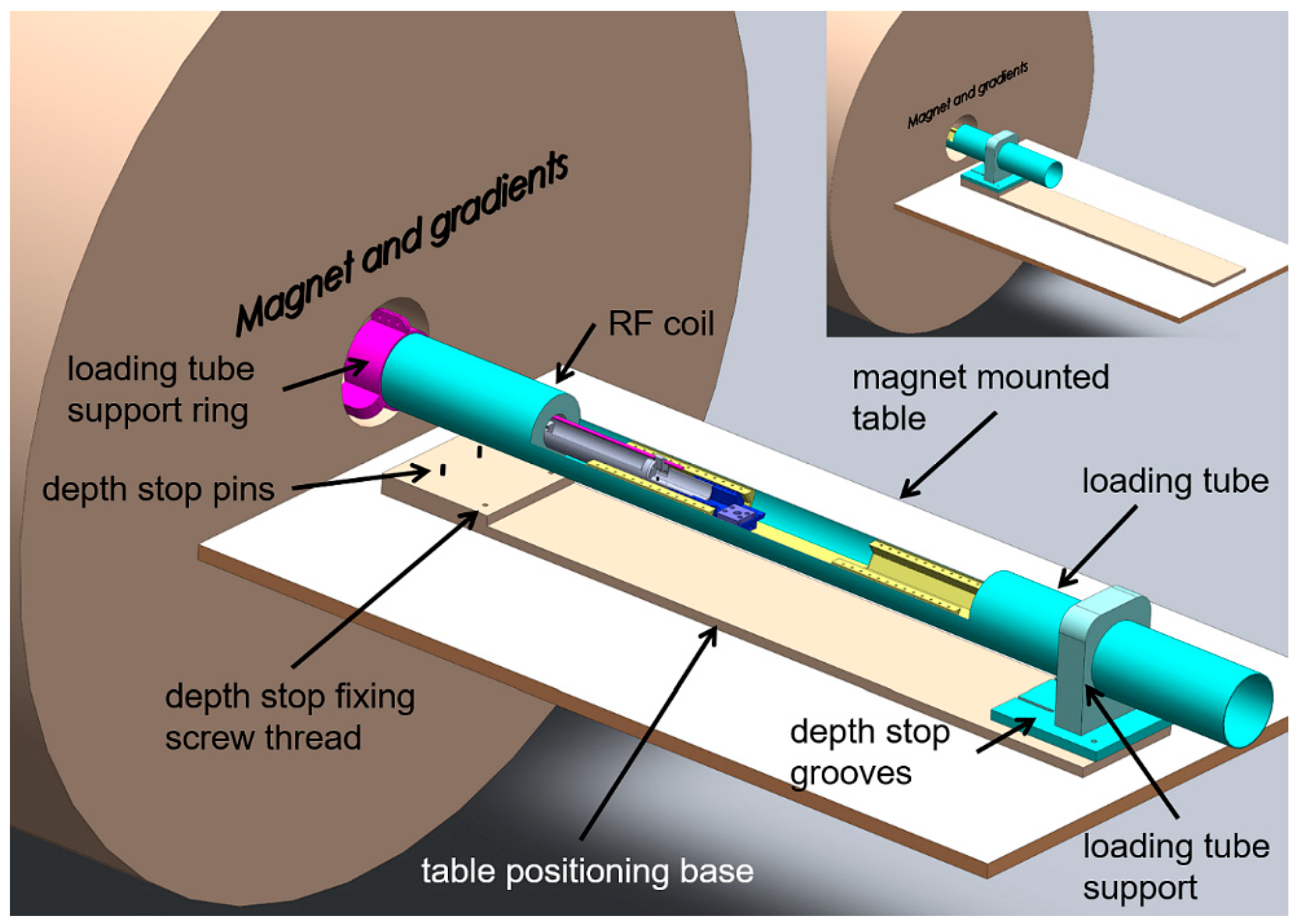
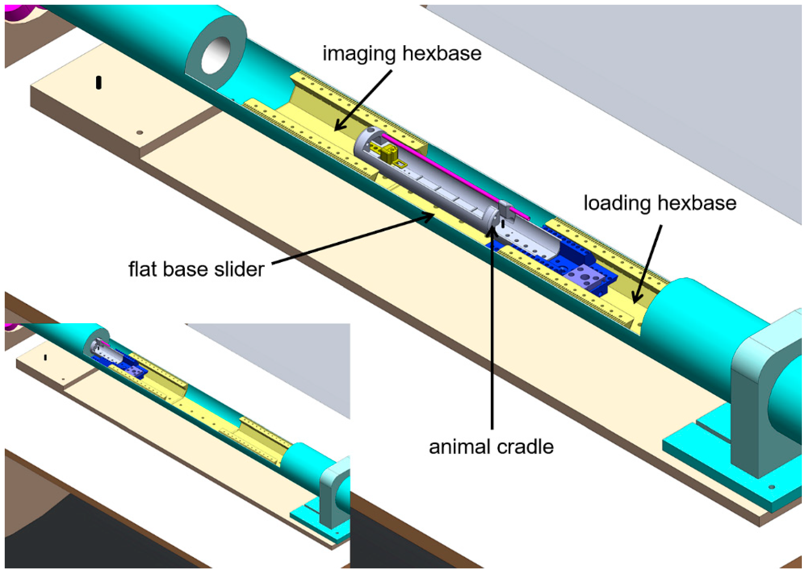
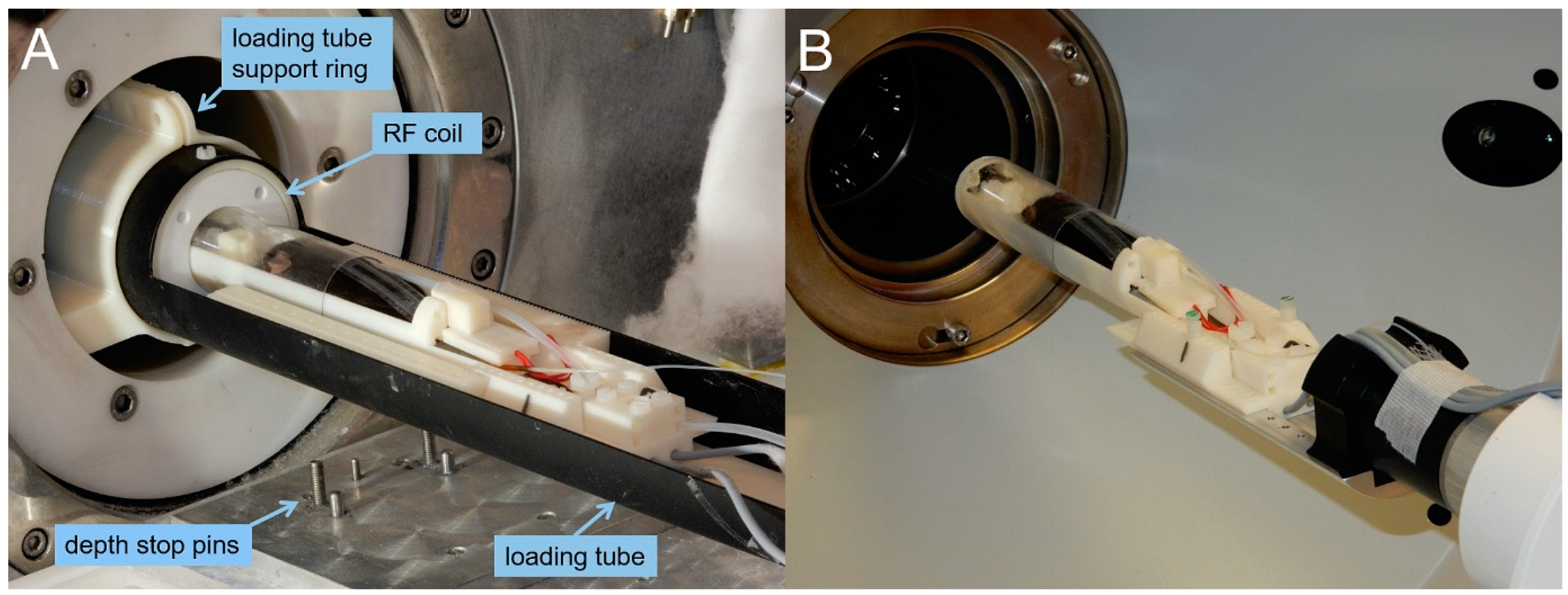
2.4. MRI System: Coil and Cradle Loading Apparatus
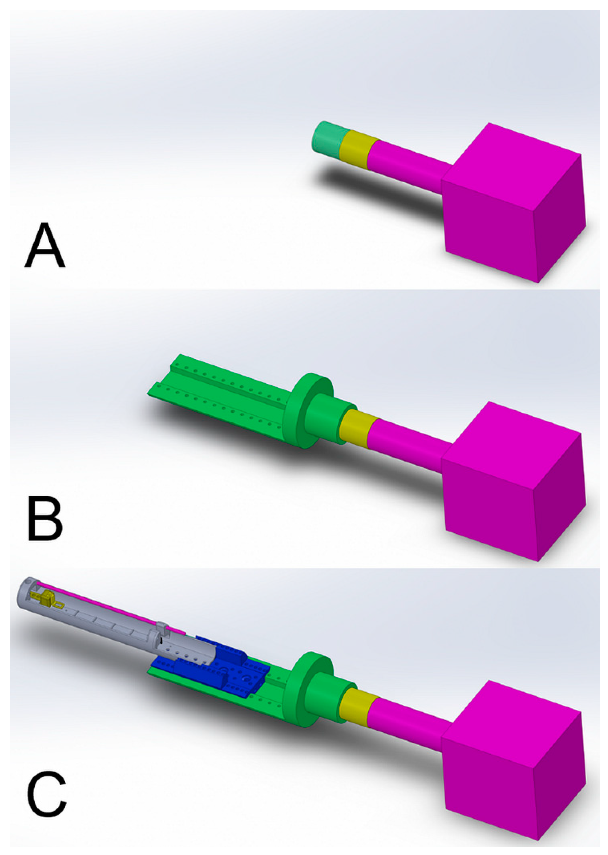
2.5. PET/SPECT/CT System: Gantry-to-Cradle Adaptor
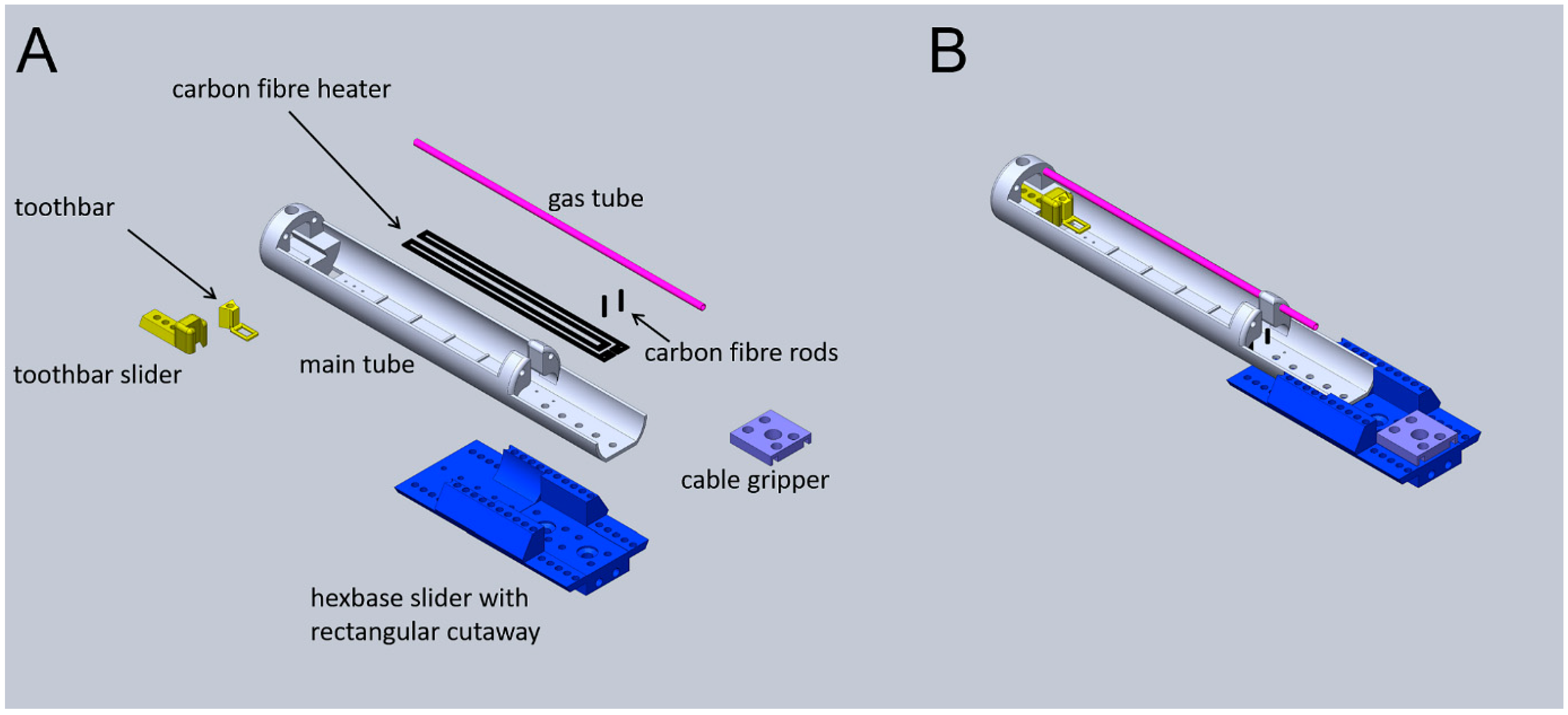
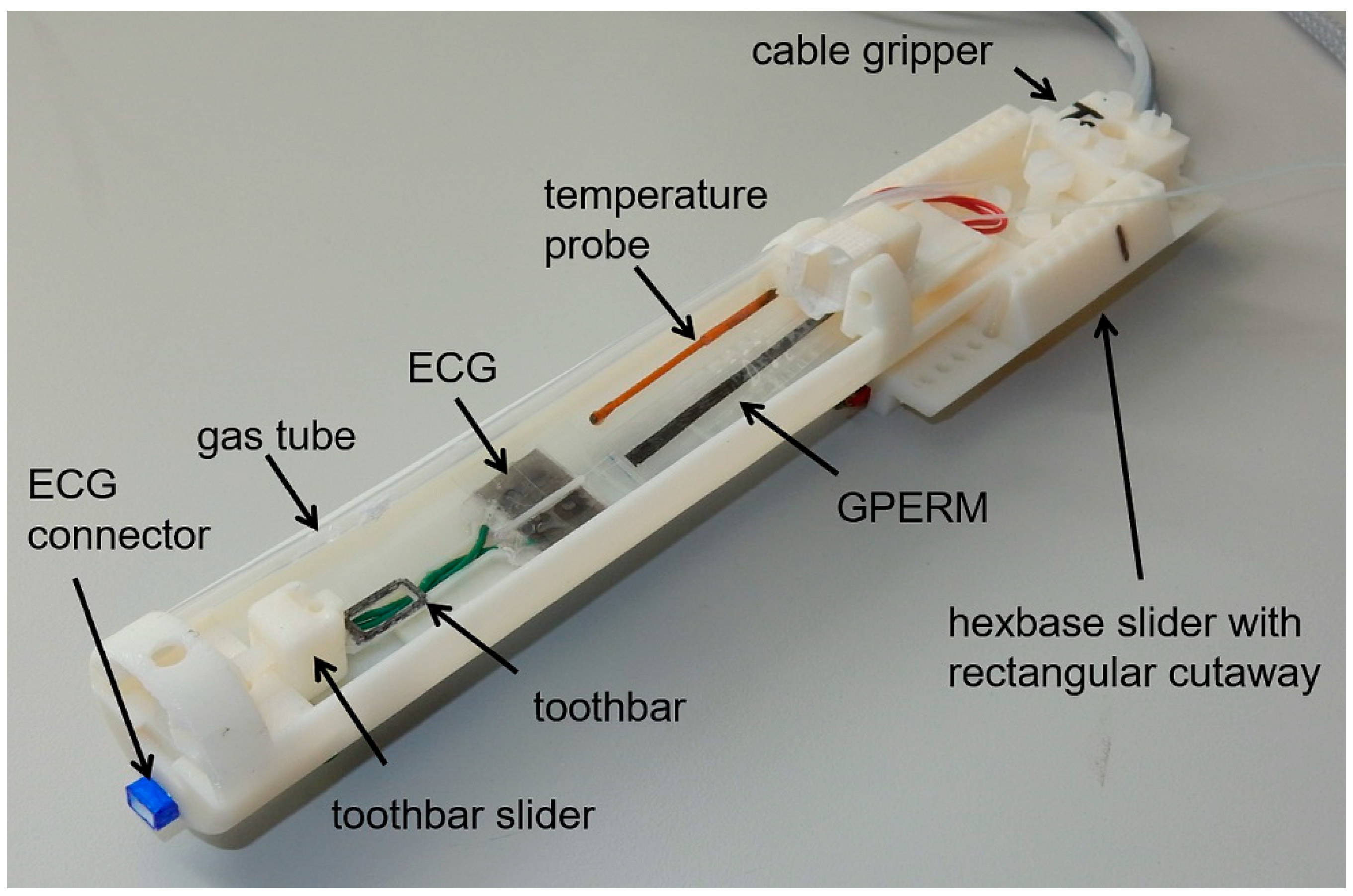
2.6. Animal Cradles: Assembly and Peripherals
2.6.1. Production of Heating Resistor
2.6.2. Production of Gas Delivery Tube
2.6.3. Production of Graphene Piezo-Electric Respiration Monitor Device
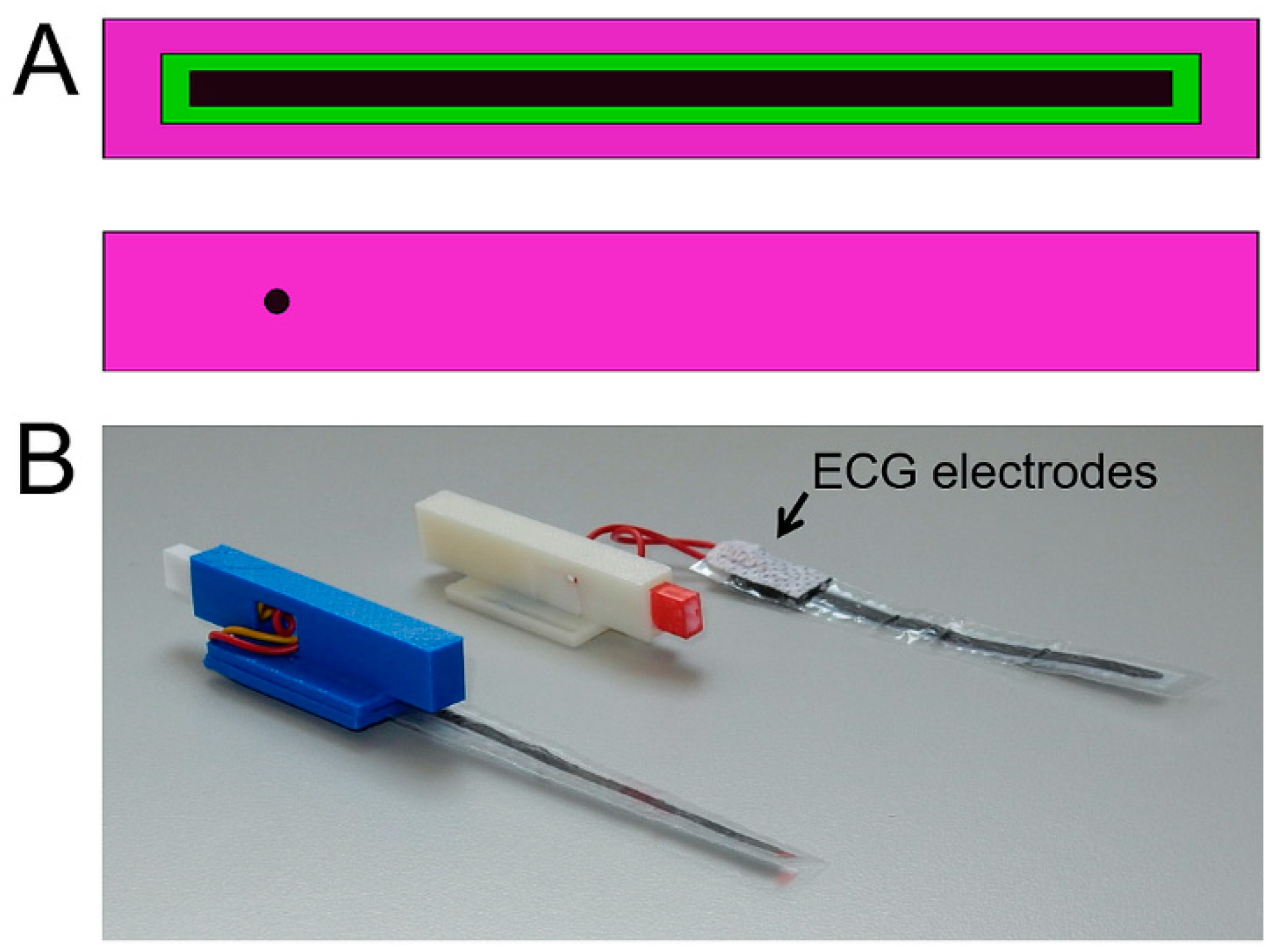
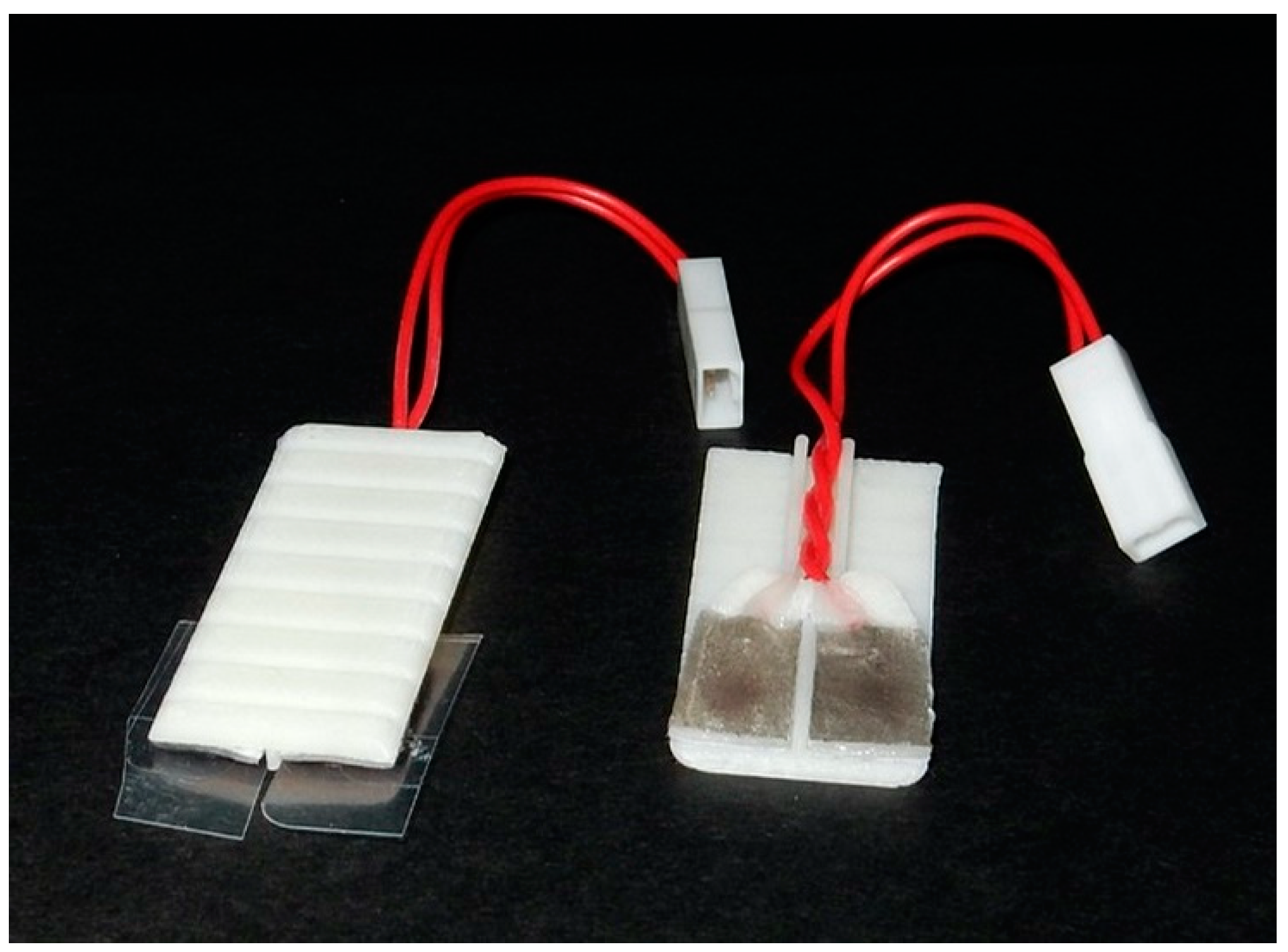
2.6.4. Production of ECG Detection Plate
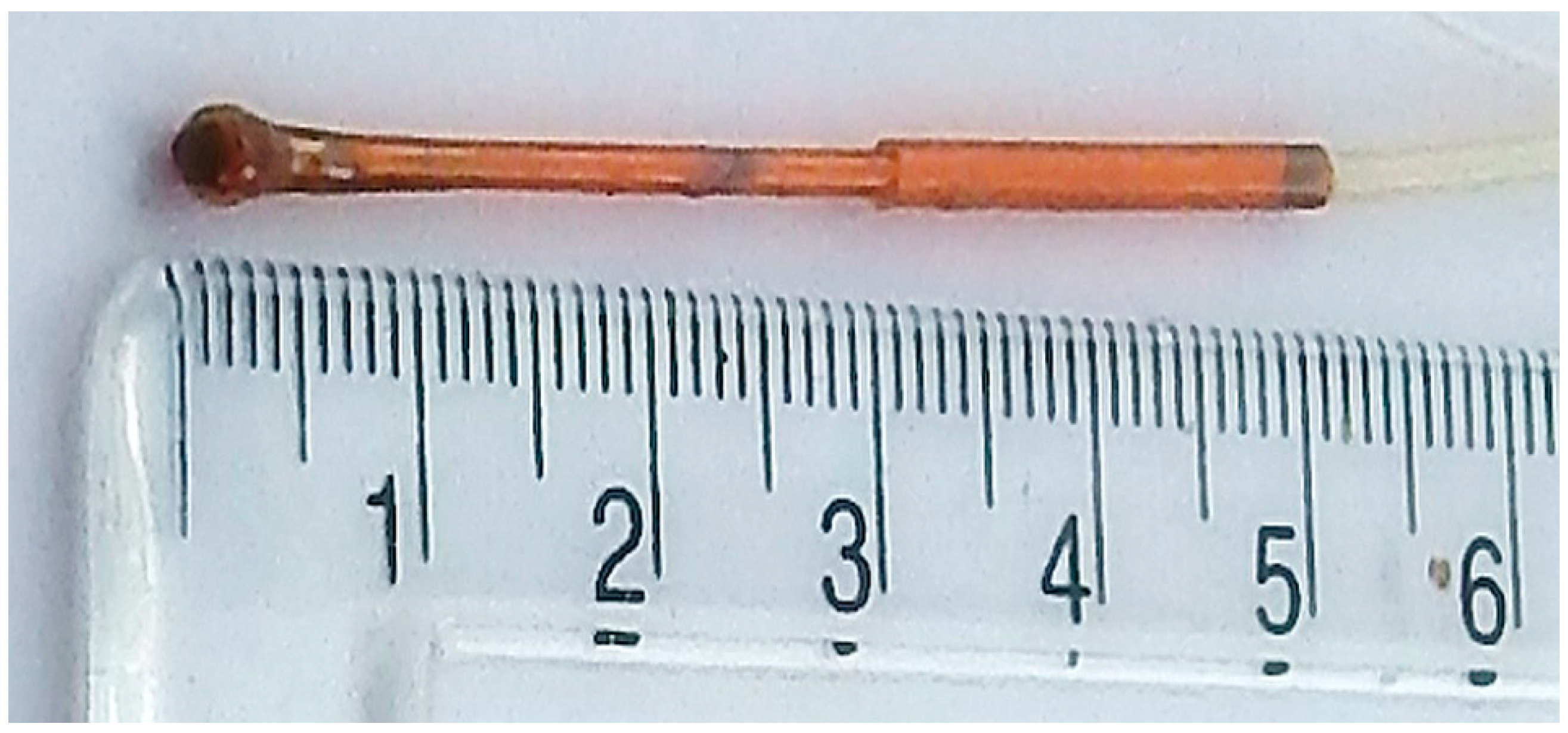
2.6.5. Production of Rectal Thermometer Shaft
2.7. ECG and Respiration Signal Processing
2.8. Transfer of Animals in the Cradle from One Scanner to Another
2.9. Demonstration of Multi-Modal Imaging
2.9.1. MRI
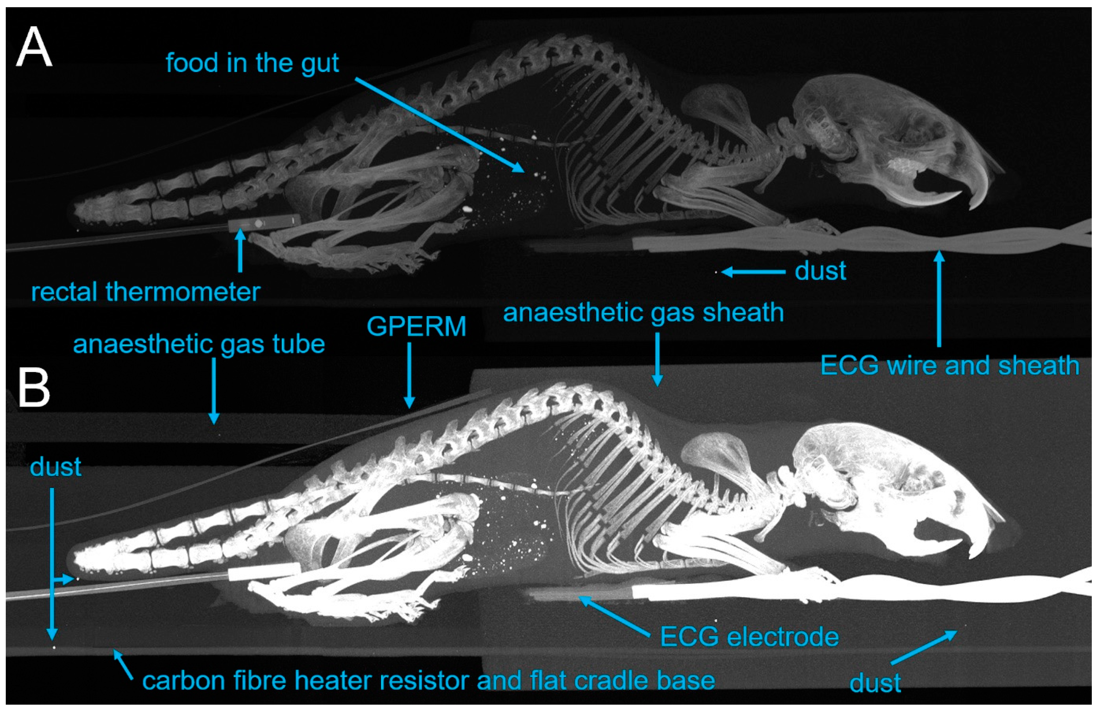
2.9.2. CT Imaging
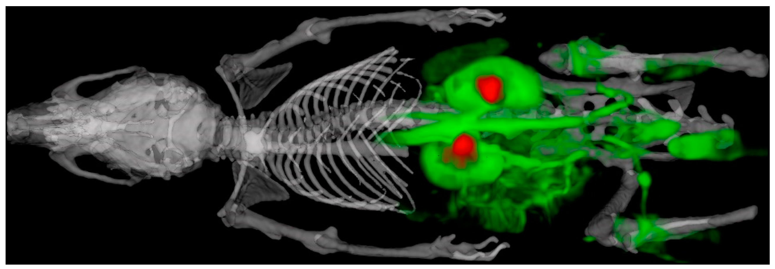
2.9.3. SPECT Imaging
3. Results and Discussion
4. Conclusions
Author Contributions
Funding
Institutional Review Board Statement
Informed Consent Statement
Acknowledgments
Conflicts of Interest
Abbreviations
| MRI | magnetic resonance imaging |
| PET | positron emission tomography |
| SPECT | Single-photon emission computed tomography |
| CT | computed tomography |
| TTL | transistor–transistor logic |
| v/v | volume to volume percent |
| RF | radiofrequency |
| hexbase | hexagonally shaped dovetail |
| 2D/3D | 2/3 dimensional |
| SARRP | Small-Animal Radiation Research Platform |
| CAD | computer-aided design |
| ECG | electrocardiogram |
| FOV | field of view |
| GPERM | graphene piezo-electric respiration monitor |
| PVDF | polyvinylidene fluoride |
| VNMRS | Varian nuclear magnetic resonance system |
| FSE | fast spin echo |
| bSSFP | balanced steady-state free precession |
| FLASH | fast low-angle shot |
| DCE-MRI | dynamic contrast-enhanced MRI |
| HE-UHR-RM | high-energy, ultra-high-resolution, rat mouse |
| MIP | maximum-intensity projection |
References
- McDougald, W.; Vanhove, C.; Lehnert, A.; Lewellen, B.; Wright, J.; Mingarelli, M.; Corral, C.A.; Schneider, J.E.; Plein, S.; Newby, D.E.; et al. Standardization of Preclinical PET/CT Imaging to Improve Quantitative Accuracy, Precision, and Reproducibility: A Multicenter Study. J. Nucl. Med. 2020, 61, 461–468. [Google Scholar] [CrossRef]
- Vanhove, C.; Bankstahl, J.P.; Kramer, S.D.; Visser, E.; Belcari, N.; Vandenberghe, S. Accurate molecular imaging of small animals taking into account animal models, handling, anaesthesia, quality control and imaging system performance. EJNMMI Phys. 2015, 2, 31. [Google Scholar] [CrossRef] [Green Version]
- Hillyar, C.R.; Knight, J.C.; Vallis, K.A.; Cornelissen, B. PET and SPECT Imaging for the Acceleration of Anti-Cancer Drug Development. Curr. Drug Targets 2015, 16, 582–591. [Google Scholar] [CrossRef]
- Choquet, P.; Goetz, C.; Aubertin, G.; Hubele, F.; Sannie, S.; Constantinesco, A. Carbon tube electrodes for electrocardiography-gated cardiac multimodality imaging in mice. J. Am. Assoc. Lab. Anim. Sci. 2011, 50, 61–64. [Google Scholar] [PubMed]
- Mirsattari, S.M.; Bihari, F.; Leung, L.S.; Menon, R.S.; Wang, Z.; Ives, J.R.; Bartha, R. Physiological monitoring of small animals during magnetic resonance imaging. J. Neurosci. Methods 2005, 144, 207–213. [Google Scholar] [CrossRef]
- Gomes, A.L.; Kinchesh, P.; Gilchrist, S.; Allen, P.D.; Lourenco, L.M.; Ryan, A.J.; Smart, S.C. Cardio-Respiratory synchronized bSSFP MRI for high throughput in vivo lung tumour quantification. PLoS ONE 2019, 14, e0212172. [Google Scholar] [CrossRef]
- Kinchesh, P.; Allen, P.D.; Gilchrist, S.; Kersemans, V.; Lanfredini, S.; Thapa, A.; O’Neill, E.; Smart, S.C. Reduced respiratory motion artefact in constant TR multi-slice MRI of the mouse. Magn. Reson. Imaging 2019, 60, 1–6. [Google Scholar] [CrossRef]
- Kinchesh, P.; Gilchrist, S.; Beech, J.S.; Gomes, A.L.; Kersemans, V.; Newman, R.G.; Vojnovic, B.; Allen, P.D.; Brady, M.; Muschel, R.J.; et al. Prospective gating control for highly efficient cardio-respiratory synchronised short and constant TR MRI in the mouse. Magn. Reson. Imaging 2018, 53, 20–27. [Google Scholar] [CrossRef] [PubMed]
- Kersemans, V.; Gilchrist, S.; Wallington, S.; Allen, P.D.; Gomes, A.L.; Dias, G.M.; Cornelissen, B.; Kinchesh, P.; Smart, S.C. A Carbon-Fiber Sheet Resistor for MR-, CT-, SPECT-, and PET-Compatible Temperature Maintenance in Small Animals. Tomography 2019, 5, 274–281. [Google Scholar] [CrossRef] [PubMed]
- Vaissier, P.E.; Beekman, F.J.; Goorden, M.C. Similarity-regulation of OS-EM for accelerated SPECT reconstruction. Phys. Med. Biol. 2016, 61, 4300–4315. [Google Scholar] [CrossRef] [PubMed]
- Heinrich, M.P.; Jenkinson, M.; Bhushan, M.; Matin, T.; Gleeson, F.V.; Brady, S.M.; Schnabel, J.A. MIND: Modality independent neighbourhood descriptor for multi-modal deformable registration. Med. Image Anal. 2012, 16, 1423–1435. [Google Scholar] [CrossRef]
- Kersemans, V.; Beech, J.S.; Gilchrist, S.; Kinchesh, P.; Allen, P.D.; Thompson, J.; Gomes, A.L.; D’Costa, Z.; Bird, L.; Tullis, I.D.C.; et al. An efficient and robust MRI-guided radiotherapy planning approach for targeting abdominal organs and tumours in the mouse. PLoS ONE 2017, 12, e0176693. [Google Scholar] [CrossRef] [PubMed] [Green Version]
- Gilchrist, S.; Kinchesh, P.; Zarghami, N.; Khrapitchev, A.A.; Sibson, N.R.; Kersemans, V.; Smart, S.C. Improved detection of molecularly targeted iron oxide particles in mouse brain using B0 field stabilised high resolution MRI. Magn. Reson. Imaging 2020, 67, 101–108. [Google Scholar] [CrossRef] [PubMed]
- Kersemans, V.; Wallington, S.; Allen, P.D.; Gilchrist, S.; Kinchesh, P.; Browning, R.; Vallis, K.A.; Schilling, K.; Holdship, P.; Stork, L.A.; et al. Manganese-free chow, a refined non-invasive solution to reduce gastrointestinal signal for T1-weighted magnetic resonance imaging of the mouse abdomen. Lab. Anim. 2019. [Google Scholar] [CrossRef] [Green Version]
- Tweedie, M.E.; Kersemans, V.; Gilchrist, S.; Smart, S.; Warner, J.H. Electromagnetically Transparent Graphene Respiratory Sensors for Multi-Modal Small Animal Imaging. Adv. Healthc. Mater. 2020, 9, 2001222. [Google Scholar] [CrossRef]
- Baker, M. 1500 scientists lift the lid on reproducibility. Nature 2016, 533, 452–454. [Google Scholar] [CrossRef] [Green Version]
- Busemann Sokole, E.; Plachcinska, A.; Britten, A. Committee EP. Acceptance testing for nuclear medicine instrumentation. Eur. J. Nucl. Med. Mol. Imaging. 2010, 37, 672–681. [Google Scholar] [CrossRef]
- Kilkenny, C.; Altman, D.G. Improving bioscience research reporting: ARRIVE-ing at a solution. Lab. Anim. 2010, 44, 377–378. [Google Scholar] [CrossRef] [Green Version]
- Kilkenny, C.; Browne, W.J.; Cuthill, I.C.; Emerson, M.; Altman, D.G. Improving bioscience research reporting: The ARRIVE guidelines for reporting animal research. PLoS Biol. 2010, 8, e1000412. [Google Scholar] [CrossRef]
- Nelson, G.S.; Perez, J.; Vilalta, M.; Ali, R.; Graves, E. Facilitating multimodal preclinical imaging studies in mice by using an immobilization bed. Comp. Med. 2011, 61, 499–504. [Google Scholar]
- McCarroll, R.E.; Rubinstein, A.E.; Kingsley, C.V.; Yang, J.; Yang, P.; Court, L.E. 3D-Printed Small-Animal Immobilizer for Use in Preclinical Radiotherapy. J. Am. Assoc. Lab. Anim. Sci. 2015, 54, 545–548. [Google Scholar] [PubMed]


Publisher’s Note: MDPI stays neutral with regard to jurisdictional claims in published maps and institutional affiliations. |
© 2021 by the authors. Licensee MDPI, Basel, Switzerland. This article is an open access article distributed under the terms and conditions of the Creative Commons Attribution (CC BY) license (http://creativecommons.org/licenses/by/4.0/).
Share and Cite
Kersemans, V.; Gilchrist, S.; Allen, P.D.; Wallington, S.; Kinchesh, P.; Prentice, J.; Tweedie, M.; Warner, J.H.; Smart, S.C. A System-Agnostic, Adaptable and Extensible Animal Support Cradle System for Cardio-Respiratory-Synchronised, and Other, Multi-Modal Imaging of Small Animals. Tomography 2021, 7, 39-54. https://0-doi-org.brum.beds.ac.uk/10.3390/tomography7010004
Kersemans V, Gilchrist S, Allen PD, Wallington S, Kinchesh P, Prentice J, Tweedie M, Warner JH, Smart SC. A System-Agnostic, Adaptable and Extensible Animal Support Cradle System for Cardio-Respiratory-Synchronised, and Other, Multi-Modal Imaging of Small Animals. Tomography. 2021; 7(1):39-54. https://0-doi-org.brum.beds.ac.uk/10.3390/tomography7010004
Chicago/Turabian StyleKersemans, Veerle, Stuart Gilchrist, Philip Danny Allen, Sheena Wallington, Paul Kinchesh, John Prentice, Martin Tweedie, Jamie H. Warner, and Sean C. Smart. 2021. "A System-Agnostic, Adaptable and Extensible Animal Support Cradle System for Cardio-Respiratory-Synchronised, and Other, Multi-Modal Imaging of Small Animals" Tomography 7, no. 1: 39-54. https://0-doi-org.brum.beds.ac.uk/10.3390/tomography7010004