Author Contributions
Conceptualization, M.M. and M.D.; methodology, P.T. and M.C.; validation, A.C. and R.M. (Riccardo Marano); investigation, E.L.; writing—original draft preparation, M.M. and M.D.; writing—review and editing, A.C.; visualization, A.M.; supervision, L.N.; project administration, R.M. (Riccardo Manfredi). All authors have read and agreed to the published version of the manuscript.
Figure 1.
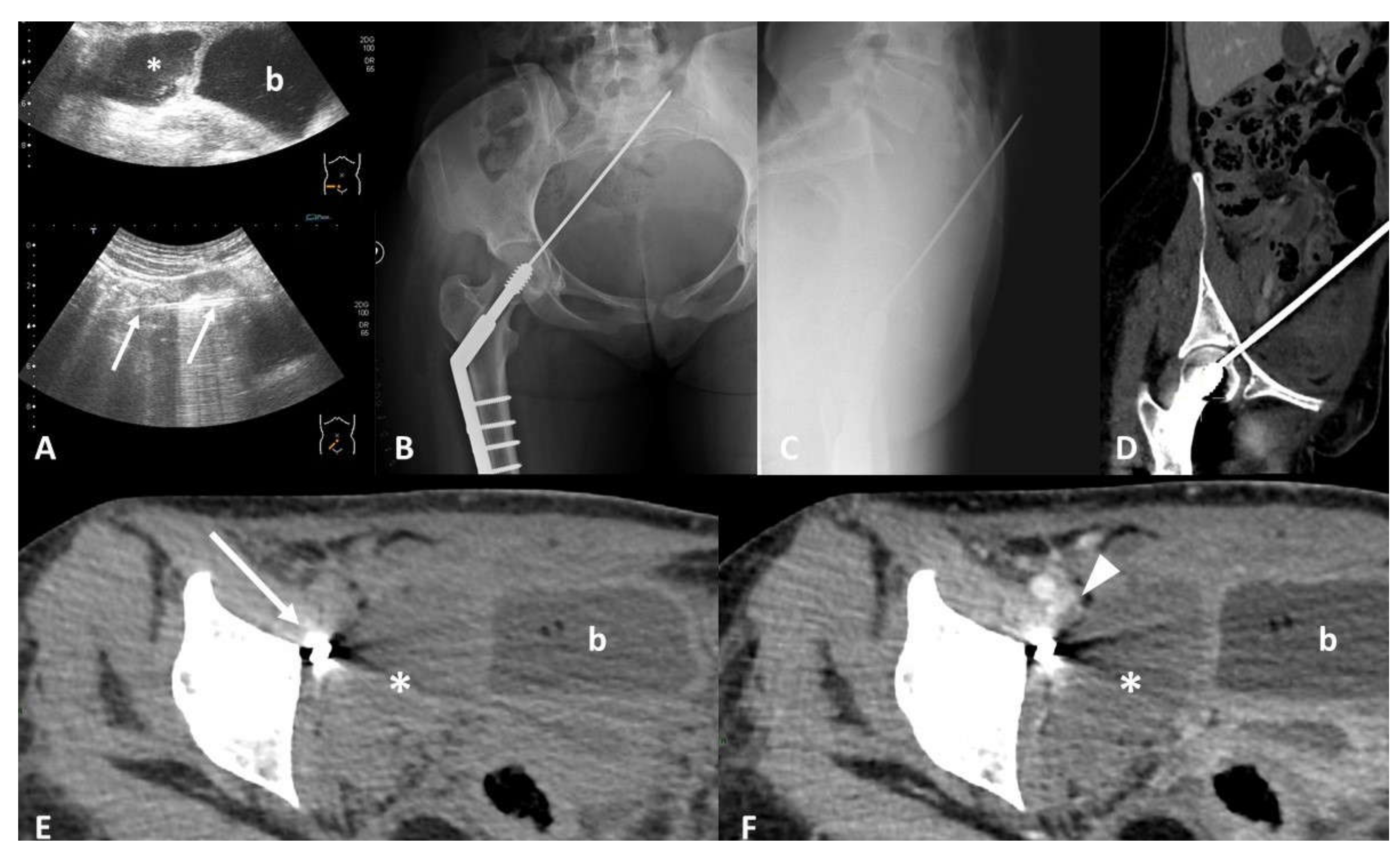
Device identification and recognition. Twenty-nine-year-old female with acute abdominal pain after surgical repair of a traumatic femoral neck fracture. Ultrasound scans (A) show a hypoechoic collection (*) in the right iliac fossa, close to the bladder (b), and a linear hyperechoic image with sonographic artifacts (arrows). Frontal (B) and lateral (C) radiographs show a sharp portion of the osteosynthesis passing through the pelvis, with the tip into the soft tissue of the anterior abdominal wall. Computed Tomography (CT) multiplanar reconstruction images better show the course of the misplaced device from the femoral head to the anterior abdominal wall (D). Non-enhanced CT scan (E) confirms a large collection (*) in the right iliac fossa, next to the misplaced device (arrow), characterized by hematic density. Contrast-enhanced CT images (F) better define the relationship between the collection (*) and the iliac vessels, showing a hypodense filling defect (arrowhead) inside the right external iliac vein (EIV), suggesting the diagnosis of a hematic collection due to iatrogenic injury of the EIV caused by the misplaced device.
Figure 1.
Device identification and recognition. Twenty-nine-year-old female with acute abdominal pain after surgical repair of a traumatic femoral neck fracture. Ultrasound scans (A) show a hypoechoic collection (*) in the right iliac fossa, close to the bladder (b), and a linear hyperechoic image with sonographic artifacts (arrows). Frontal (B) and lateral (C) radiographs show a sharp portion of the osteosynthesis passing through the pelvis, with the tip into the soft tissue of the anterior abdominal wall. Computed Tomography (CT) multiplanar reconstruction images better show the course of the misplaced device from the femoral head to the anterior abdominal wall (D). Non-enhanced CT scan (E) confirms a large collection (*) in the right iliac fossa, next to the misplaced device (arrow), characterized by hematic density. Contrast-enhanced CT images (F) better define the relationship between the collection (*) and the iliac vessels, showing a hypodense filling defect (arrowhead) inside the right external iliac vein (EIV), suggesting the diagnosis of a hematic collection due to iatrogenic injury of the EIV caused by the misplaced device.
![Tomography 07 00024 g001]()
Figure 2.
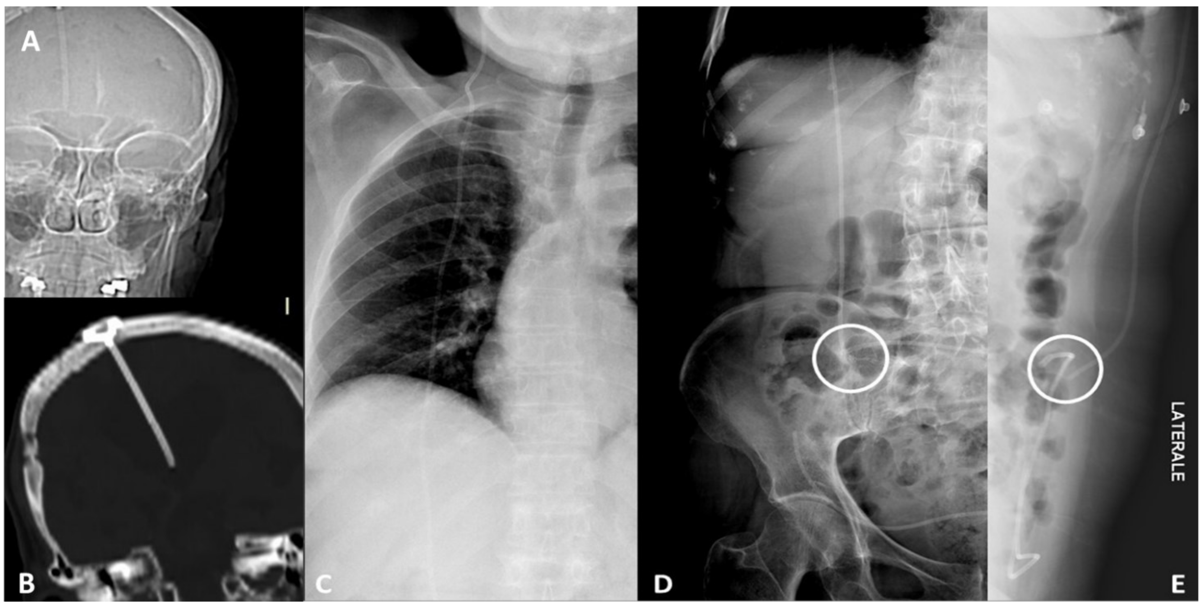
Device integrity. Ventriculoperioteneal shunt malfunction in a patient with history of hydrocephalus. CT scout view (A) and coronal CT scan (B) of the head show the correct placement of the tip of the shunt inside the right lateral ventricle. Frontal chest radiograph (C) shows the integrity of the device along its thoracic course. Frontal (D) and lateral (E) abdominal radiographs detect a fracture of the device in the right lower quadrant of the abdomen.
Figure 2.
Device integrity. Ventriculoperioteneal shunt malfunction in a patient with history of hydrocephalus. CT scout view (A) and coronal CT scan (B) of the head show the correct placement of the tip of the shunt inside the right lateral ventricle. Frontal chest radiograph (C) shows the integrity of the device along its thoracic course. Frontal (D) and lateral (E) abdominal radiographs detect a fracture of the device in the right lower quadrant of the abdomen.
Figure 3.
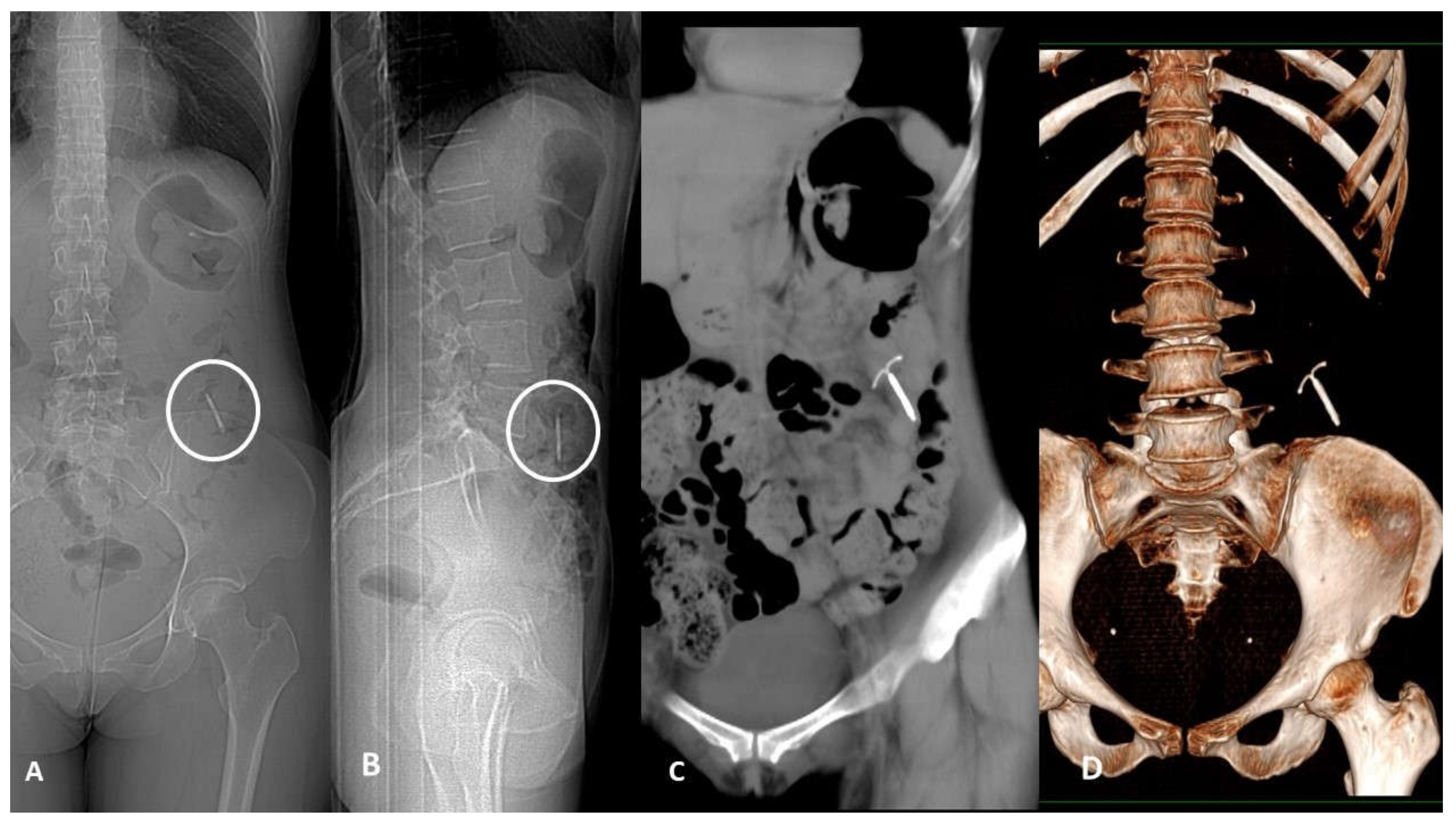
Device migration. Thirty-nine-year-old woman with acute left flank pain and history of copper Intra-uterine device (IUD) insertion 2 years earlier. Frontal (A) and lateral (B) CT scout of abdomen identify the IUD in the left lower quadrant. Non-enhanced CT scan coronal plane MIP-reformatted (C) shows device dislocation medially to descending colon in the pericolic fatty tissue; no displacement-related complications such as pneumoperitoneum or fluid collection were found. CT 3D-reconstruction (D).
Figure 3.
Device migration. Thirty-nine-year-old woman with acute left flank pain and history of copper Intra-uterine device (IUD) insertion 2 years earlier. Frontal (A) and lateral (B) CT scout of abdomen identify the IUD in the left lower quadrant. Non-enhanced CT scan coronal plane MIP-reformatted (C) shows device dislocation medially to descending colon in the pericolic fatty tissue; no displacement-related complications such as pneumoperitoneum or fluid collection were found. CT 3D-reconstruction (D).
Figure 4.
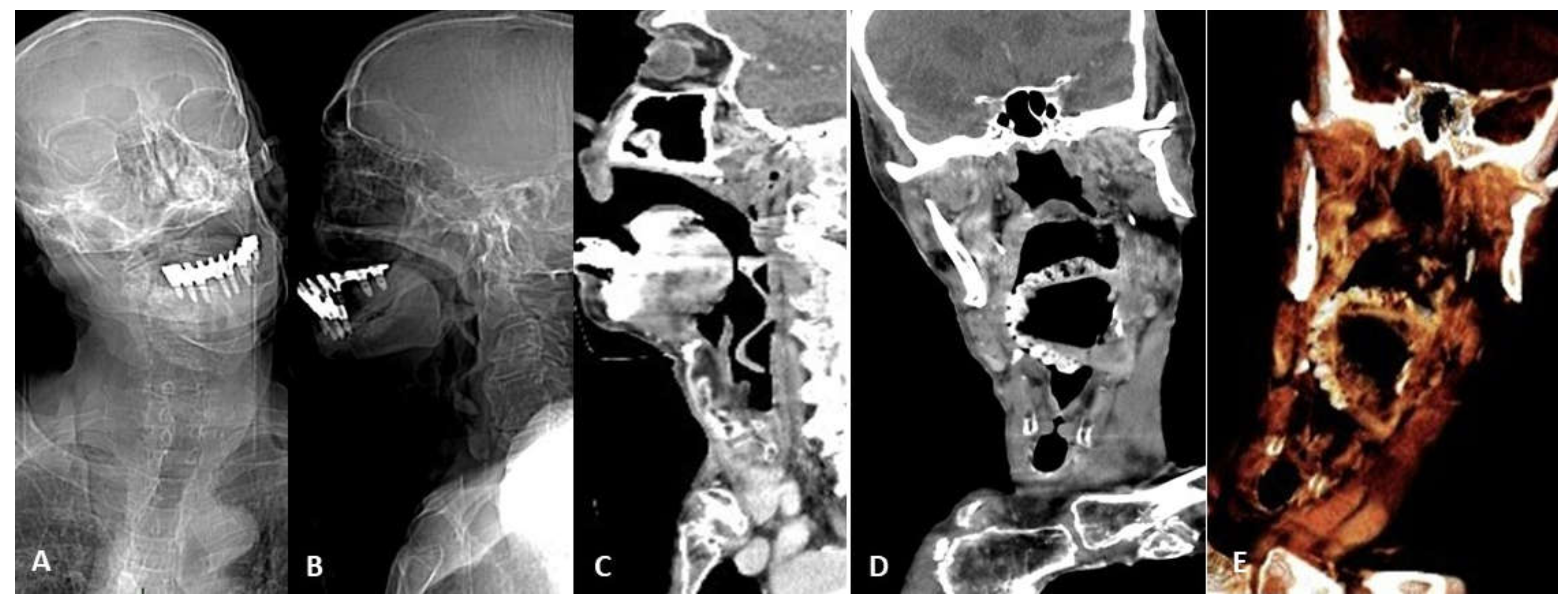
Device migration. Eighty-seven-year-old man affected by Alzheimer disease and asphyxiation crisis. Frontal (A) and lateral (B) head and neck CT scout views show denture migration with hypopharynx impaction. Contrast-enhanced CT sagittal (C) and coronal (D) scans better show denture relationship with the surrounding structures and demonstrate anterior epiglottis displacement with subsequent airways restriction (arrow). 3D VR image thin slab (5 mm) view (E) better shows device migration.
Figure 4.
Device migration. Eighty-seven-year-old man affected by Alzheimer disease and asphyxiation crisis. Frontal (A) and lateral (B) head and neck CT scout views show denture migration with hypopharynx impaction. Contrast-enhanced CT sagittal (C) and coronal (D) scans better show denture relationship with the surrounding structures and demonstrate anterior epiglottis displacement with subsequent airways restriction (arrow). 3D VR image thin slab (5 mm) view (E) better shows device migration.
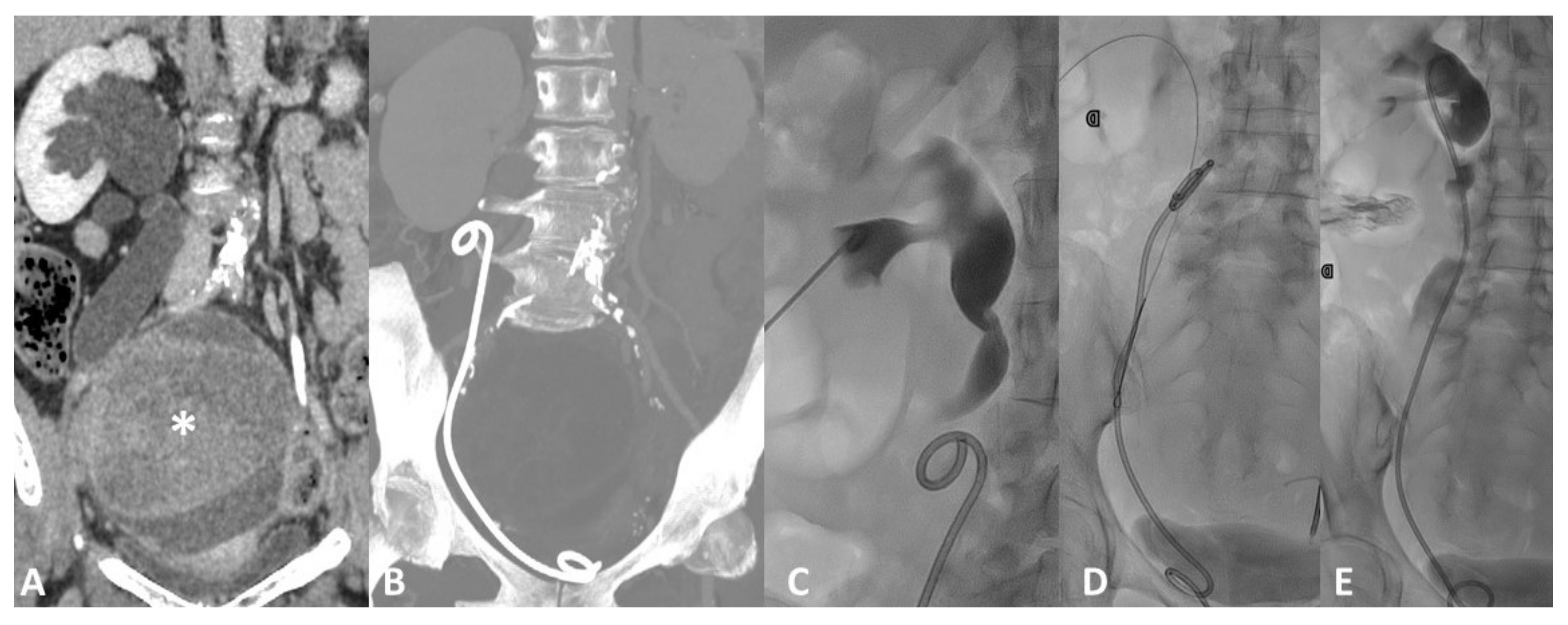
Figure 5.
Device migration. Forty-six-year-old female with rapid onset of right flank pain ad diuresis reduction 3 months after ureteral stent placement for marked hydroureteronephrosis (A) caused by an ovarian mass (*). Follow-up CT scan (B) shows displacement of the ureteral stent, slipped down in the urinary tract. Fluoroscopic image (C) shows the consequent dilatation of the renal pelvis and calyces with stasis of contrast medium caused both by the malfunction of the displaced device and by the mechanical obstruction caused by the stent itself inside the ureter. Percutaneous Stent retrieval with a goose neck snare catheter (D) and replacement (E) was the treatment of choice.
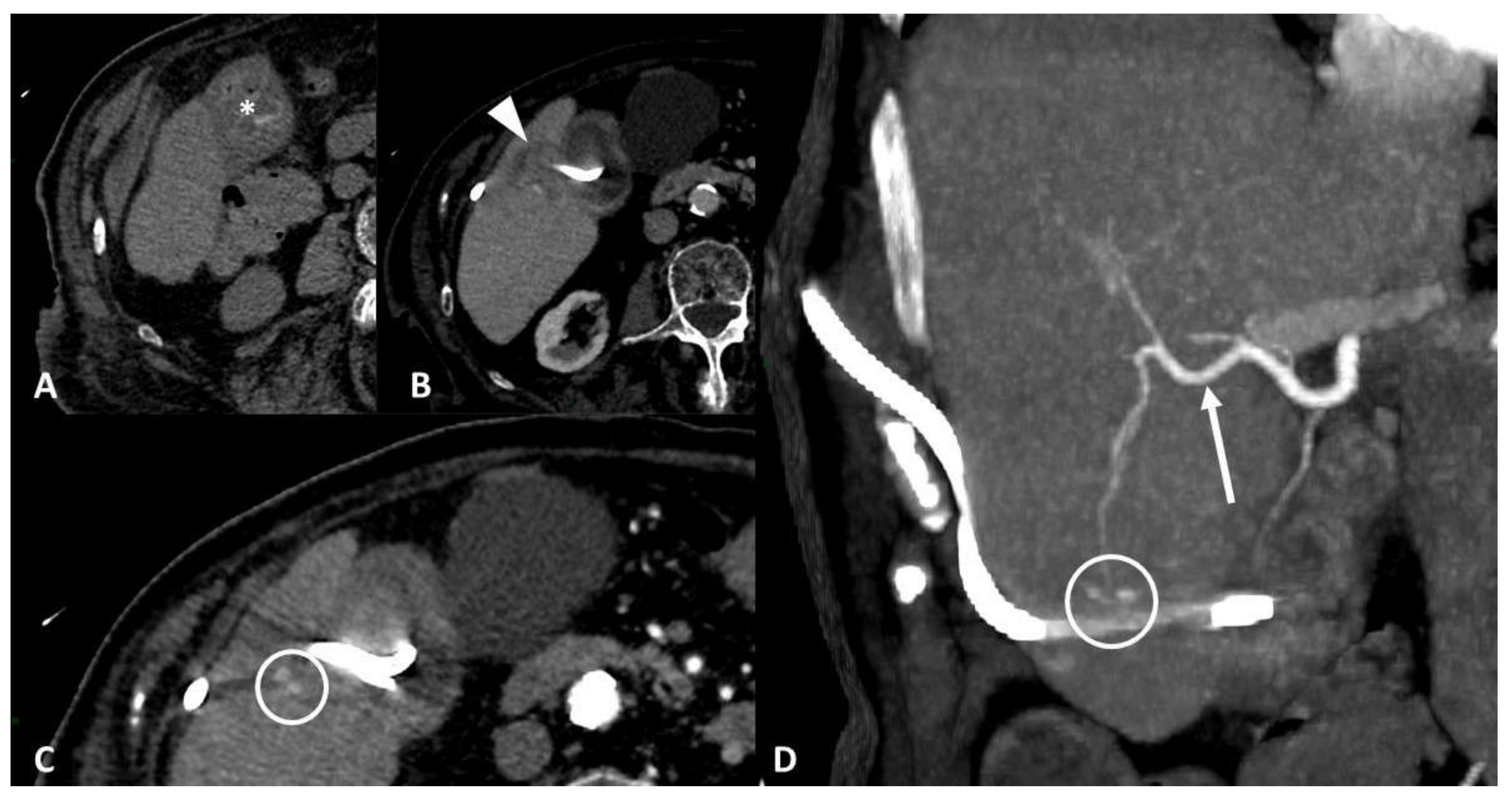
Figure 6.
Vascular injury. Seventy-five-year-old patient affected by bleeding after percutaneous cholecystostomy. Axial non-enhanced CT scan (A) shows hyperdense blood-like material inside the gallbladder (*). Contrast-enhanced CT scans (B,C) show liver parenchymal laceration (arrowhead) in segment V, next to gallbladder, with two hyperdense spots inside. Maximum intensity projection coronal image (D) shows more clearly two pseudoaneurysms of a distal branch of the right hepatic artery (arrow) along drainage course.
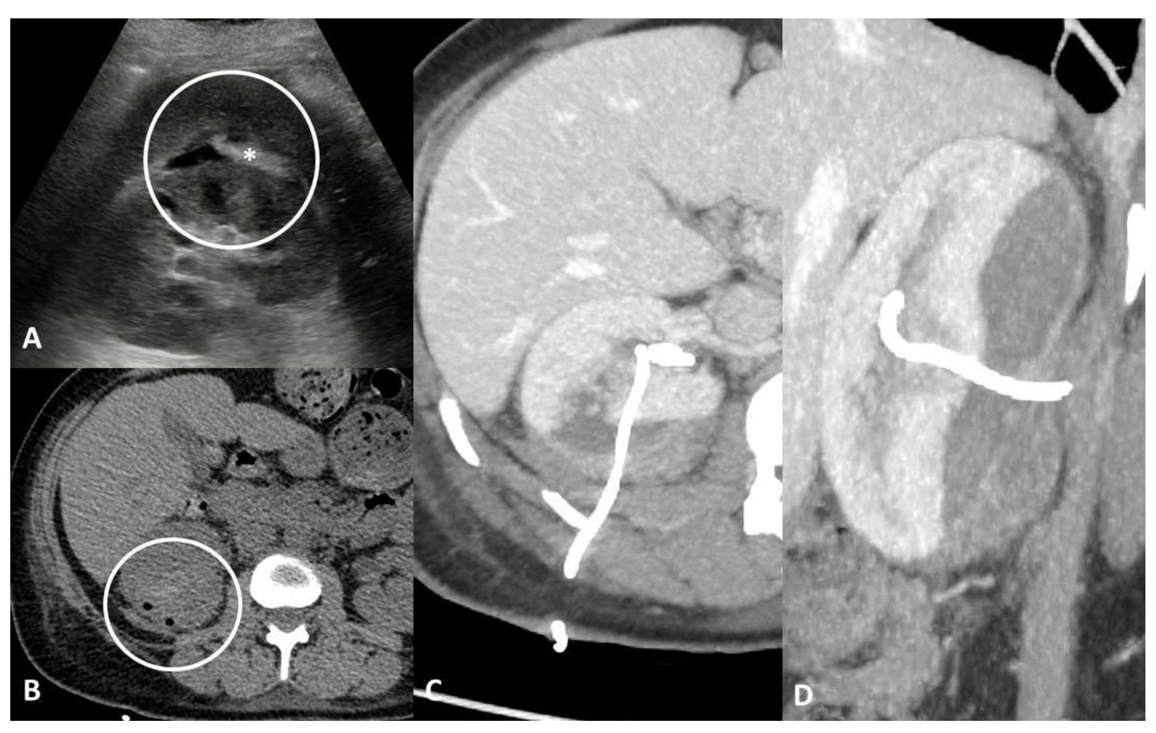
Figure 7.
Parenchymal/tissue injury. Forty-one-year-old female with persistent haematuria after percutaneous nephrostomy placement. Axial ultrasound scan (A) shows hypoechoic collection of the right kidney with hyperechoic material inside (*). Non-enhanced CT scans (B) confirm the presence of a subcapsular hematic collection associated with a heterogeneous density area in the posterior renal parenchyma. Axial (C) and coronal (D) maximum intensity projection CT images show more clearly the large parenchymal laceration and the direct relationship with the nephrostomy tube, without signs of active bleeding.
Figure 8.
Obstruction. Sixty-four-year-old male with a 3-day history of abdominal pain, constipation, vomiting, and a history of surgery with sleeve gastrectomy and LAGB (laparoscopic adjustable gastric banding) insertion for morbid obesity. Contrast-enhanced CT maximum intensity projection images show (A) jejunum dilatation with transition point in mesogastrium caused by gastric band displacement; (B) marked dilation of the upstream loop by fecaloid material stasis (arrow) indicates mechanical obstruction. Contrast-enhanced CT multiplanar reconstruction scans (C) show port localization in the subcutaneous tissue of the anterior abdominal wall (notched arrow) and the tip of the connecting tube in the gastric cavity (arrowhead). CT 3D-reconstruction (D) better shows device disconnection, migration, and integrity of the two components.
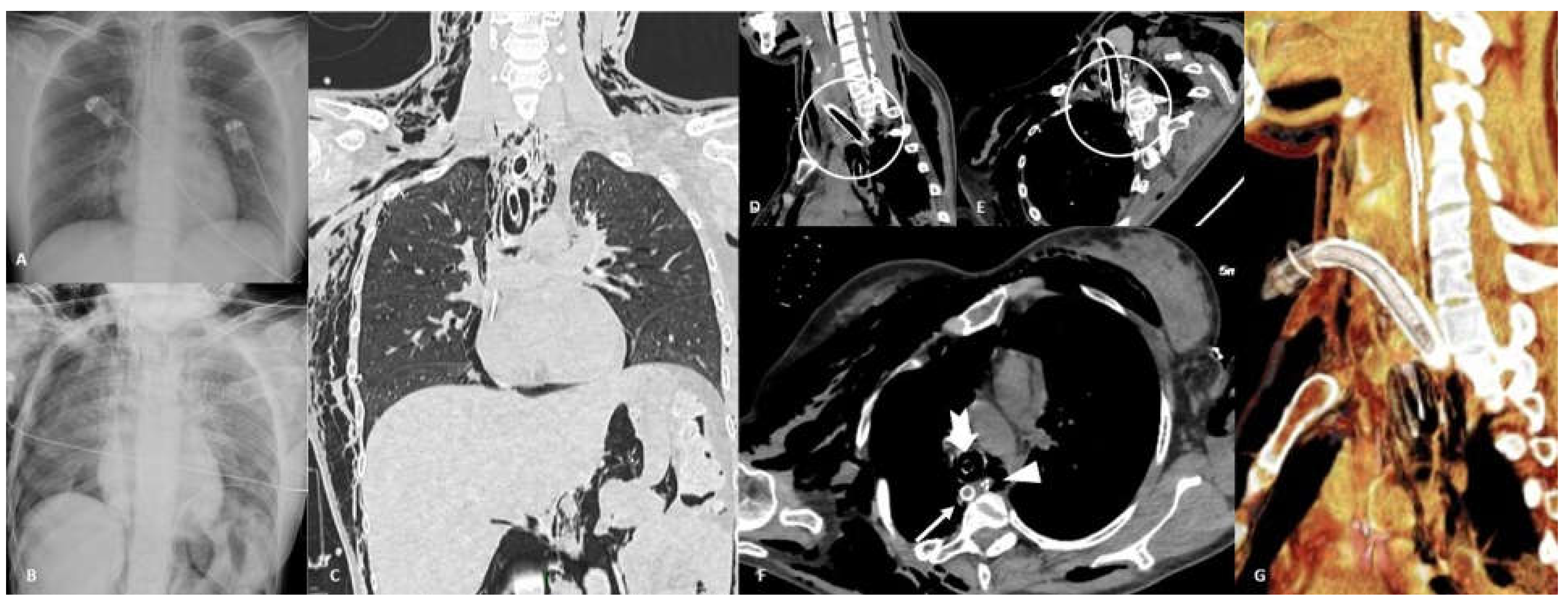
Figure 9.
Perforation. Thirty-six-year-old female affected by acute leukemia who underwent tracheostomy placement. Frontal chest radiograph before (A) and after (B) tracheostomy procedure show the development of right pneumothorax, pneumomediastinum, pneumoperitoneum, and soft tissue emphysema onset. Coronal non-contrast CT scan in lung window (C) confirms all these findings. CT unenhanced multiplanar reconstructions (D,E) show posterior tracheal wall perforation induced by the tip of the tracheostomy tube; CT axial image (F) shows displacement of tracheostomy tip in the posterior mediastinum/prevertebral soft tissue (arrow), correct position of nasogastric tube (NSG) in esophageal lumen (arrowhead), and endotracheal tube correctly cuffed (notched arrow). CT 3D-reconstruction (G) better shows tracheostomy tube malposition.
Figure 10.
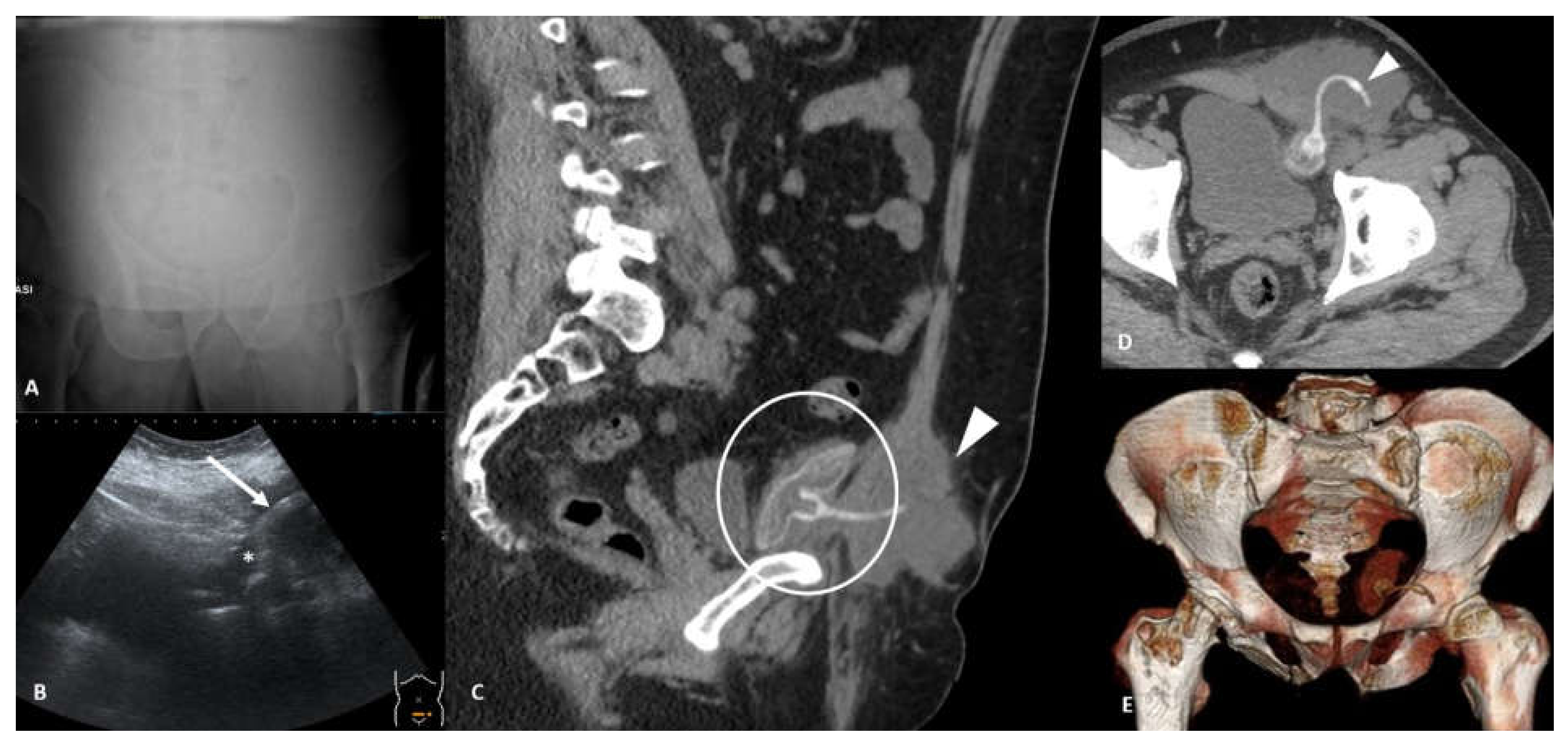
Fluid collection. Fifty-two-year-old male with history of IPP (inflatable penile prosthesis) implantation 6 years ago and recent onset of left groin pain. Frontal orthostatic radiogram (A) does not show pneumoperitoneum. Ultrasound pelvic scan (B) shows hyperechoic complex image (arrow) in left iliac fossa within a hypoechoic collection (*). Sagittal contrast-enhanced CT (C) shows IPP reservoir placed in the retropubic space of Retzius and rectus abdominis tumefaction (arrowhead). Axial non-contrast CT image (D) better shows left rectus abdominis tumefaction caused by reservoir saline loss due to disruption of IPP connecting tube (arrowhead); CT 3D-reconstruction (E) shows reservoir integrity and connecting tube disruption.
Figure 10.
Fluid collection. Fifty-two-year-old male with history of IPP (inflatable penile prosthesis) implantation 6 years ago and recent onset of left groin pain. Frontal orthostatic radiogram (A) does not show pneumoperitoneum. Ultrasound pelvic scan (B) shows hyperechoic complex image (arrow) in left iliac fossa within a hypoechoic collection (*). Sagittal contrast-enhanced CT (C) shows IPP reservoir placed in the retropubic space of Retzius and rectus abdominis tumefaction (arrowhead). Axial non-contrast CT image (D) better shows left rectus abdominis tumefaction caused by reservoir saline loss due to disruption of IPP connecting tube (arrowhead); CT 3D-reconstruction (E) shows reservoir integrity and connecting tube disruption.
Figure 11.
Systematic approach to emergencies related to medical devices.
Figure 11.
Systematic approach to emergencies related to medical devices.


