4.1. Evaluation of the Original Row Hammer PUF
The original Row Hammer PUF, which was introduced by Schaller et al. [
1], in 2017, is based on a firmware implementation that was querying the PUF during an early stage during DRAM initialisation, before caching had been enabled by the boot-loader. This implementation was tested using the values of the Row Hammer PUF parameters shown in
Table 1. It was examined how these parameters affected the number of observed bit flips and, then, this implementation was evaluated, using a fixed parameter configuration, with regards to its uniqueness, robustness and entropy. Additionally, it was briefly discussed how temperature variations could influence the Row Hammer PUF.
Furthermore, due to the lack of information about the distribution of true and anti-cells it was necessary to explore the correlation between such parameters as the
hammer row IV and the
PUF row IV of the Row Hammer PUF and its PUF behaviour experimentally, by testing various parameter settings. The reason for this was that most vendors of COTS, including the manufacturers of the PandaBoard, treat such implementation details regarding their hardware components as the distribution of true and anti-cells in the DRAM, as intellectual property and thus will not disclose them. However, one potential approach to retrieve the layout of true cells (and anti-cells) would be to initialize the DRAM with ‘
0xFF’ (or ‘
0x00’), disable the DRAM refresh operation and read back the memory contents after a period of several hours or days, i.e., at the end of the decay process. Such an approach has indeed been successfully tested by Kraft et al. [
51].
In the original evaluation, three different memory regions, each located on one individual PandaBoard, had been measured, with each such memory region considered as a PUF instance. Therefore, three different PandaBoards had been employed for the evaluation of the Row Hammer PUF. For all of the measurements, the PUF address was fixed. For each parameter combination, 20 measurements were taken.
As
Table 1 reveals, the original paper by Schaller et al. [
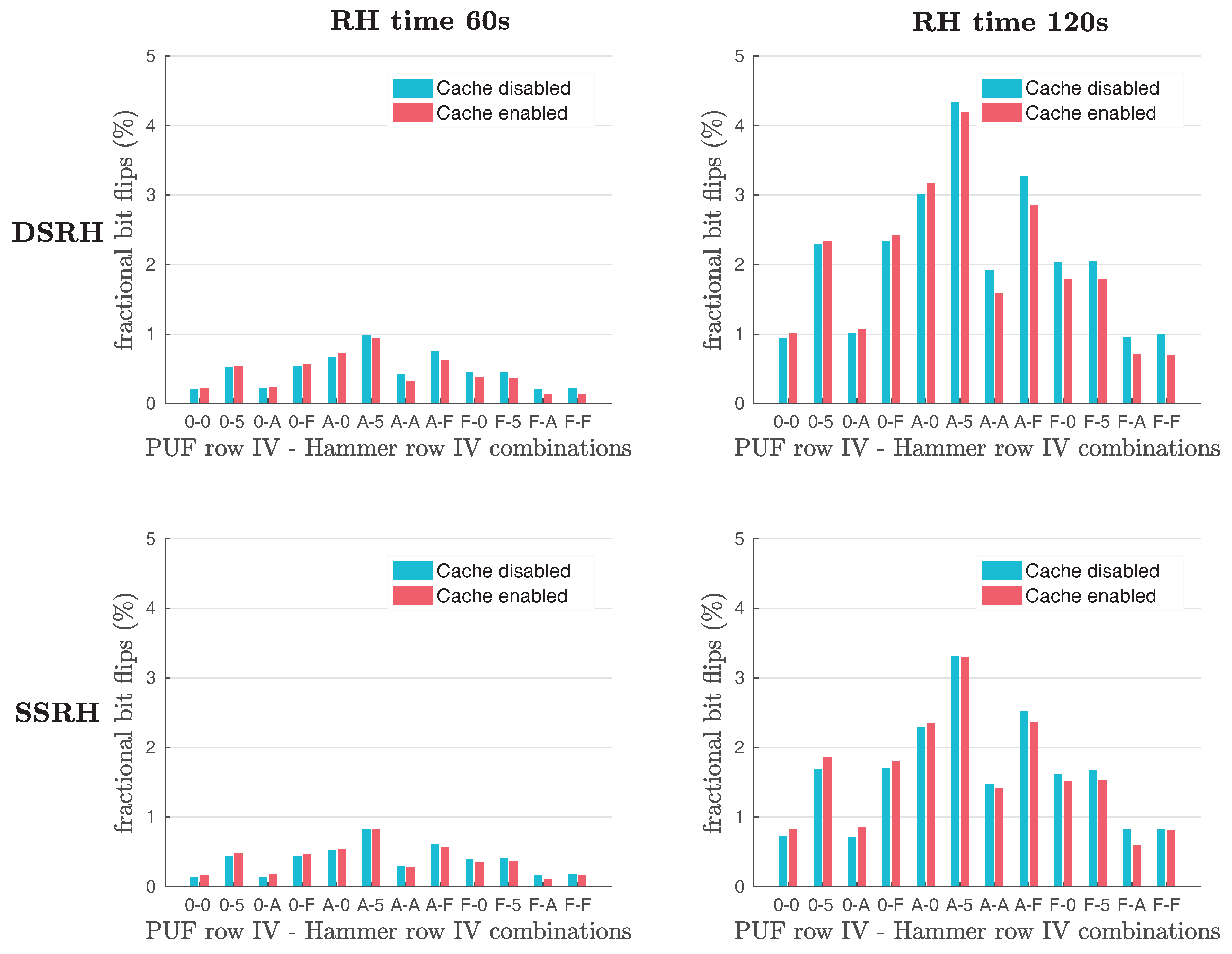
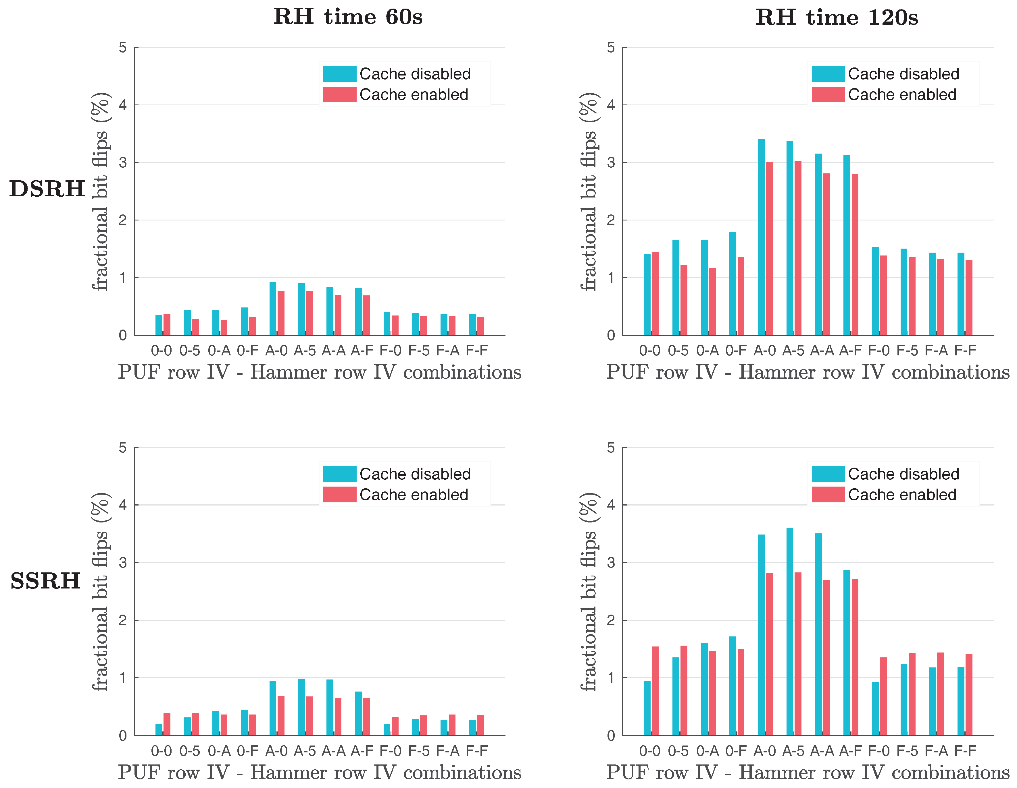
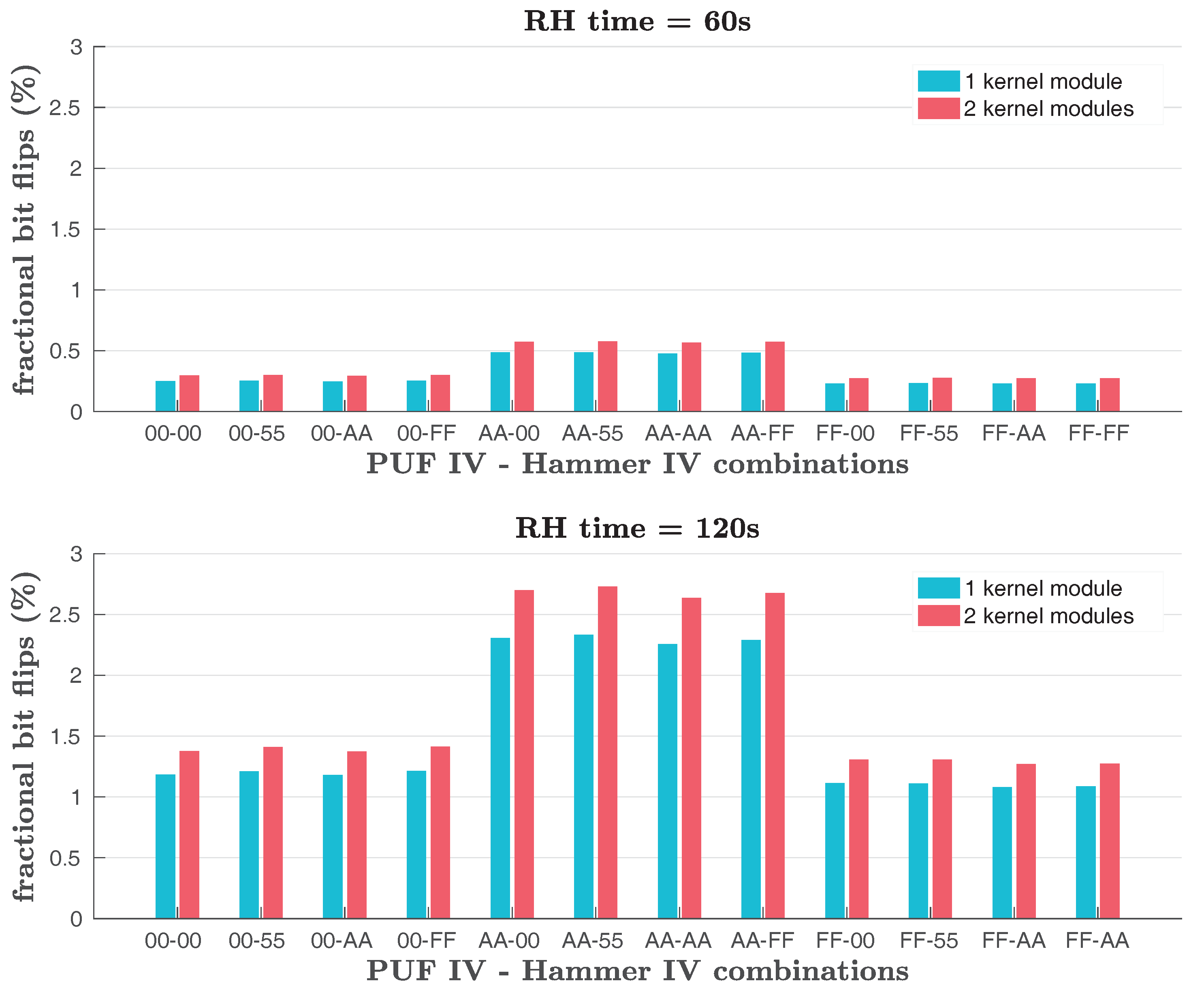
1] considered a number of different values for the Row Hammer PUF parameters, focusing, however, on evaluating configuration settings that were expected to yield a good PUF. To extract the maximum possible entropy from the PUF, Schaller et al. primarily strived to maximize the number of bit flips. For this purpose, they needed to identify which parameters had the largest influence on the amount of bit flips. Their results, shown in
Table 2 and
Figure 3, reveal that the
hammer row IV and the
PUF row IV play a significant role in the amount of bit flips produced.
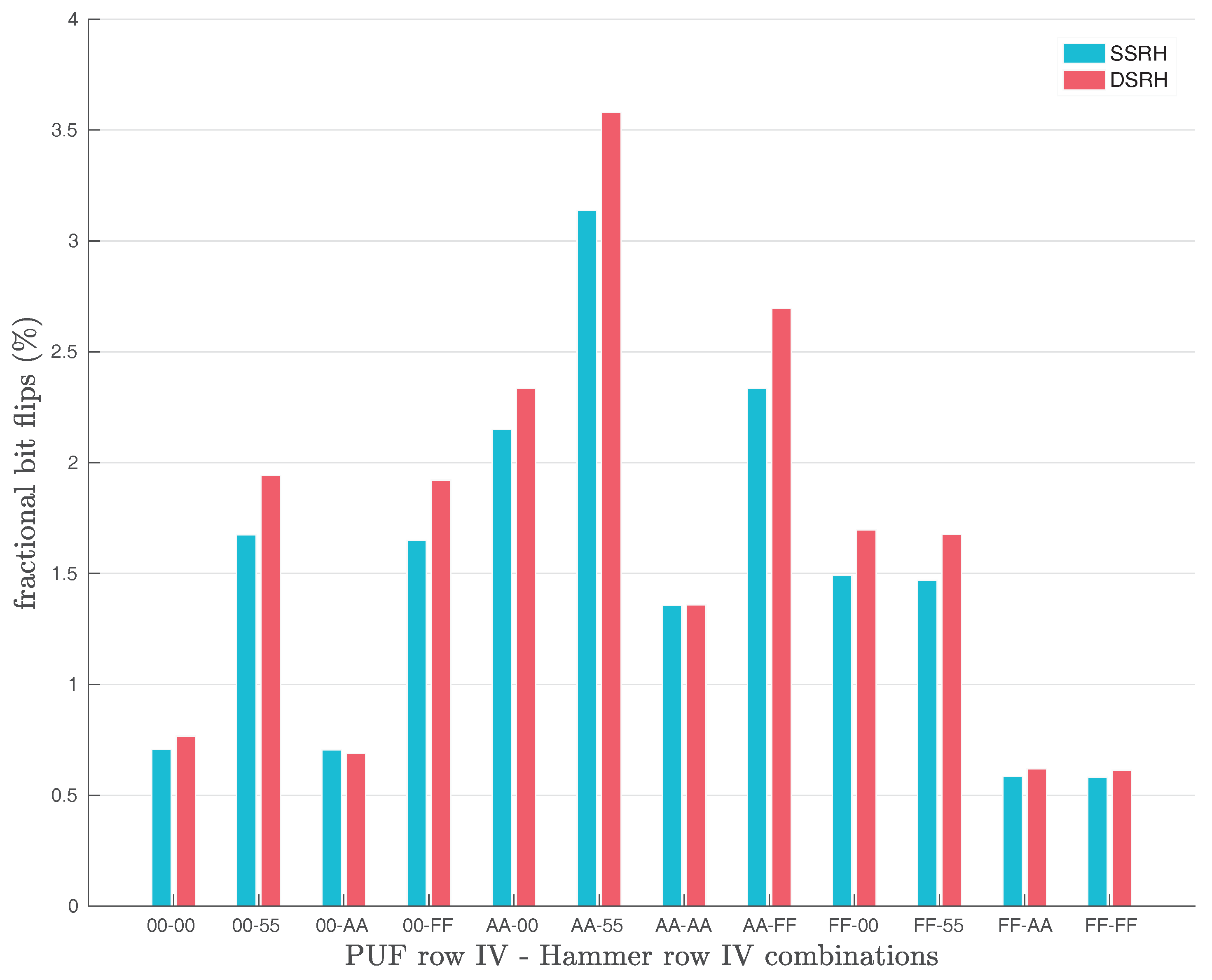
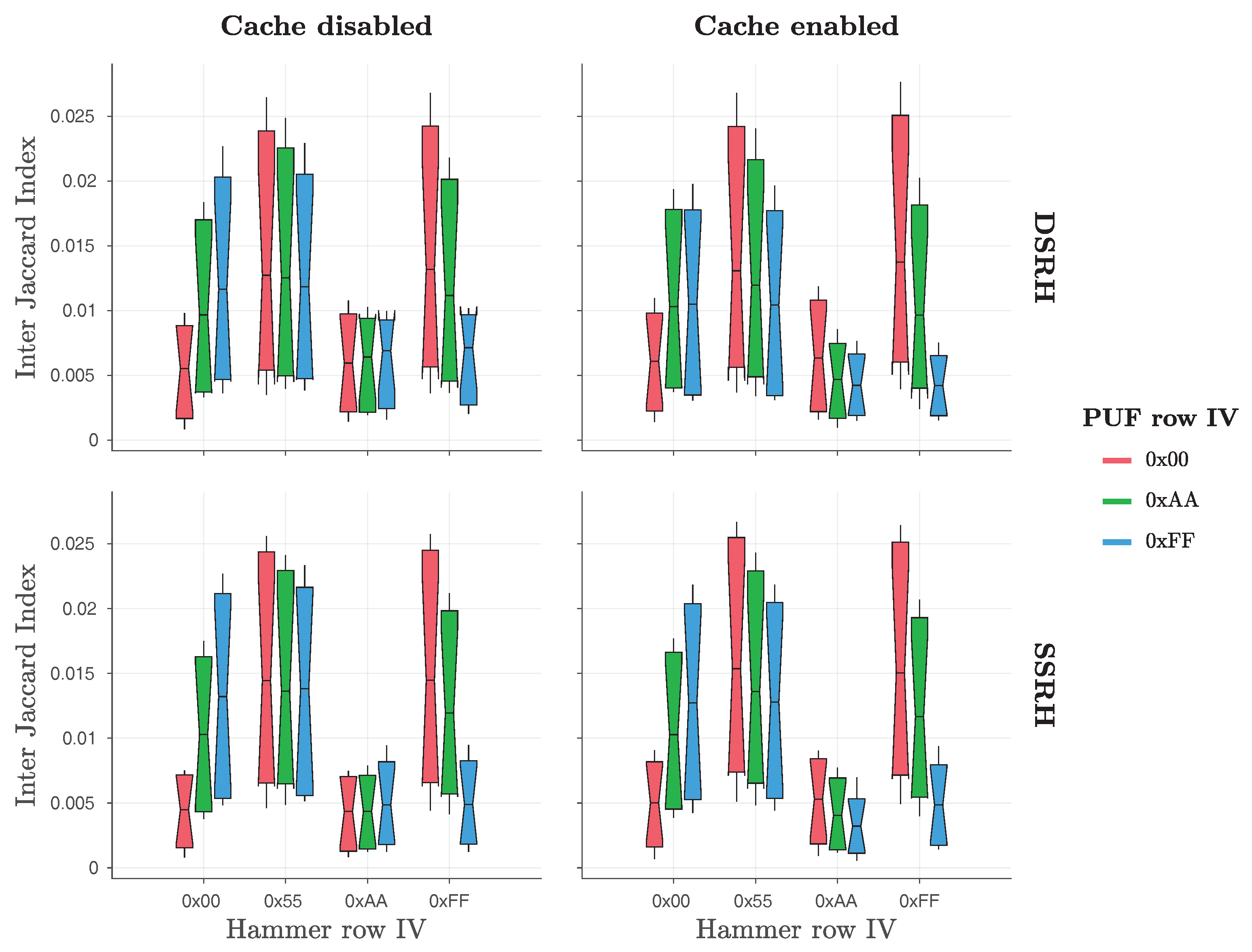
Furthermore, Schaller et al. [
1] examined also the effects of Single-Sided (
SSRH) and Double-Sided Row Hammering (
DSRH) on the number of bit flips observed in the original Row Hammer PUF responses, as shown in
Figure 4. Their results show that the use of
DSRH results in slightly more bit flips observed than the use of
SSRH. However, the difference in the number of bit flips produced with the two methods does not appear to be significant, as
Figure 4 clearly indicates.
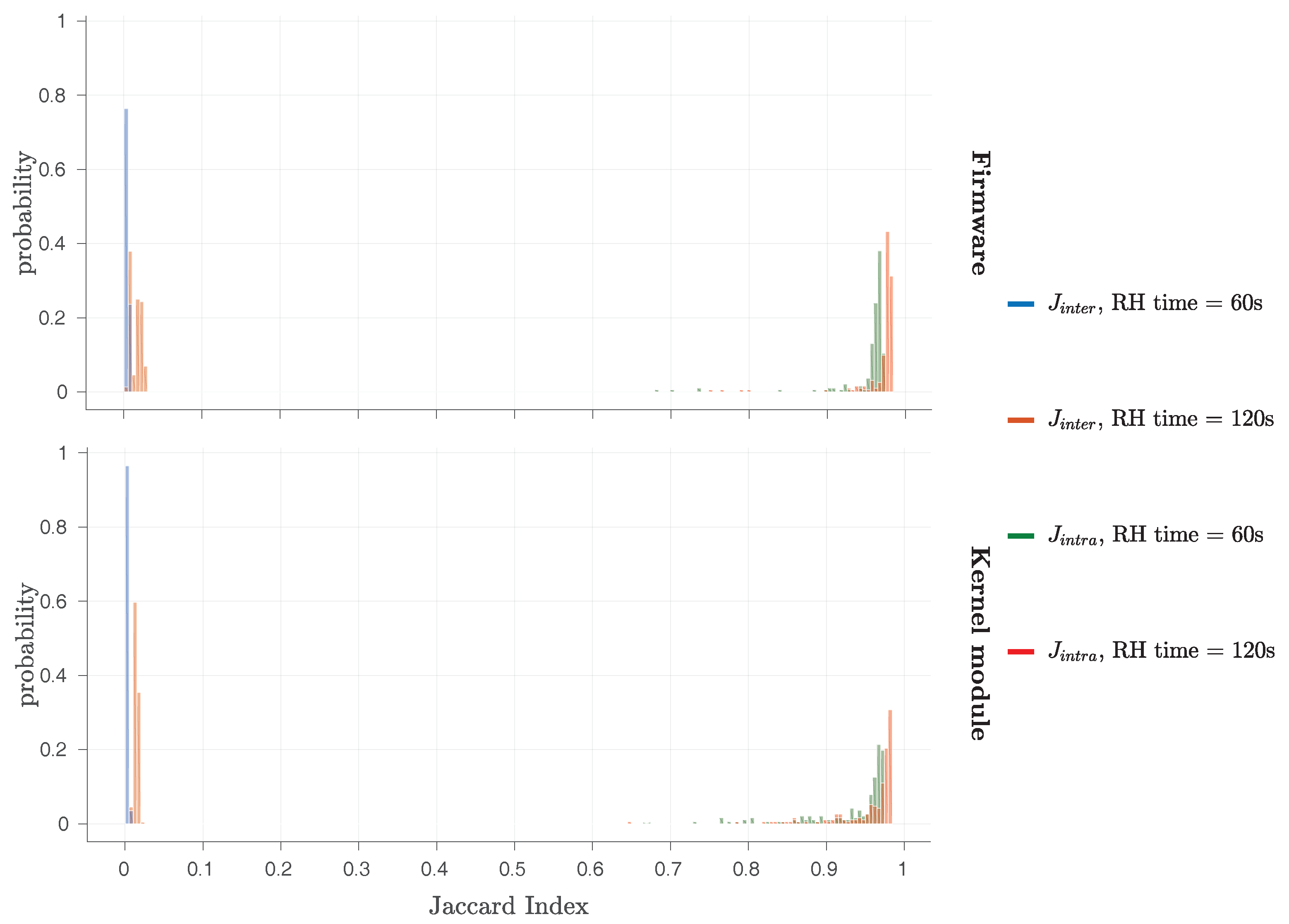
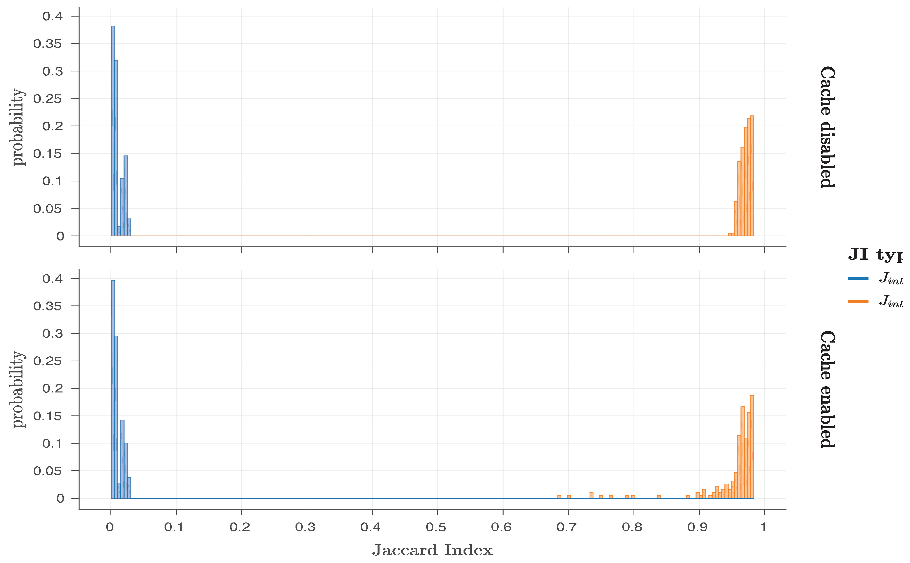
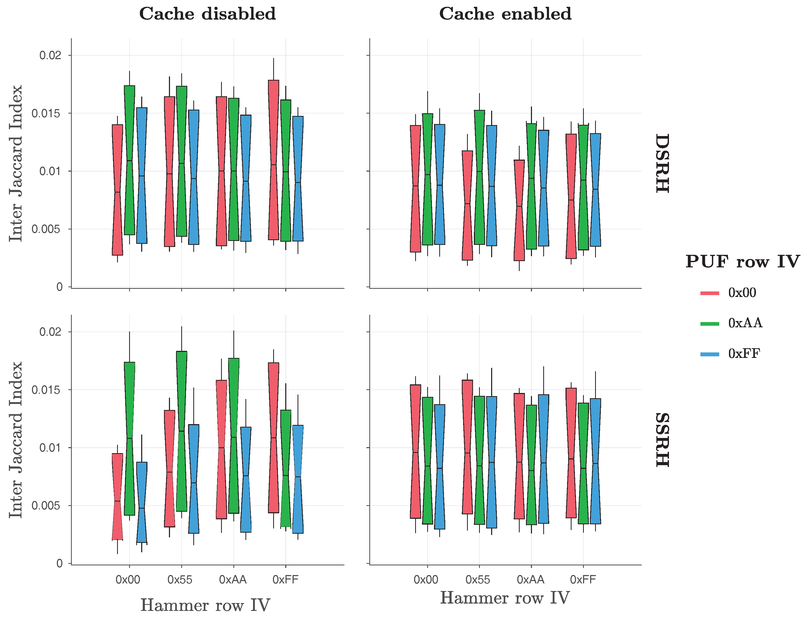
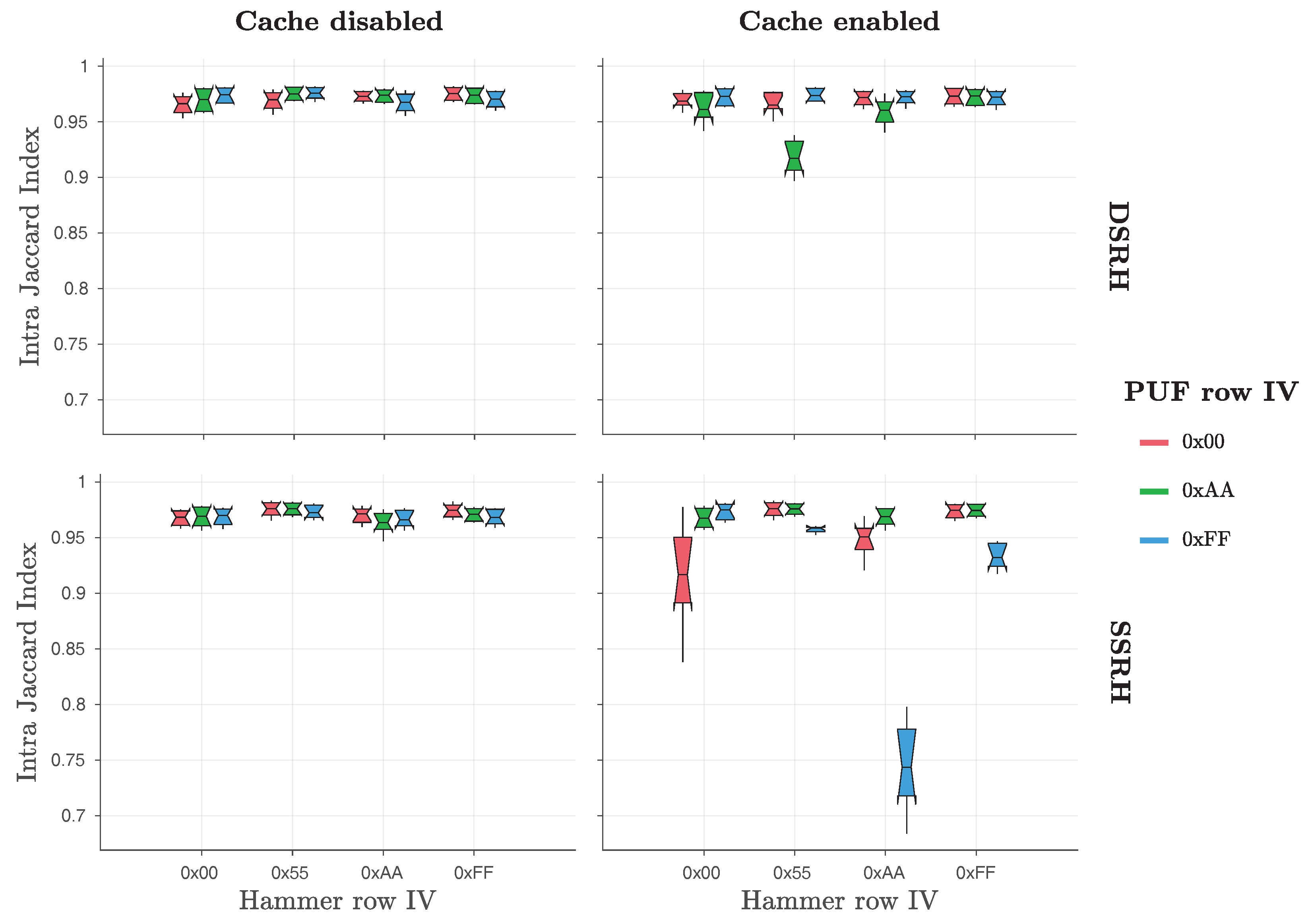
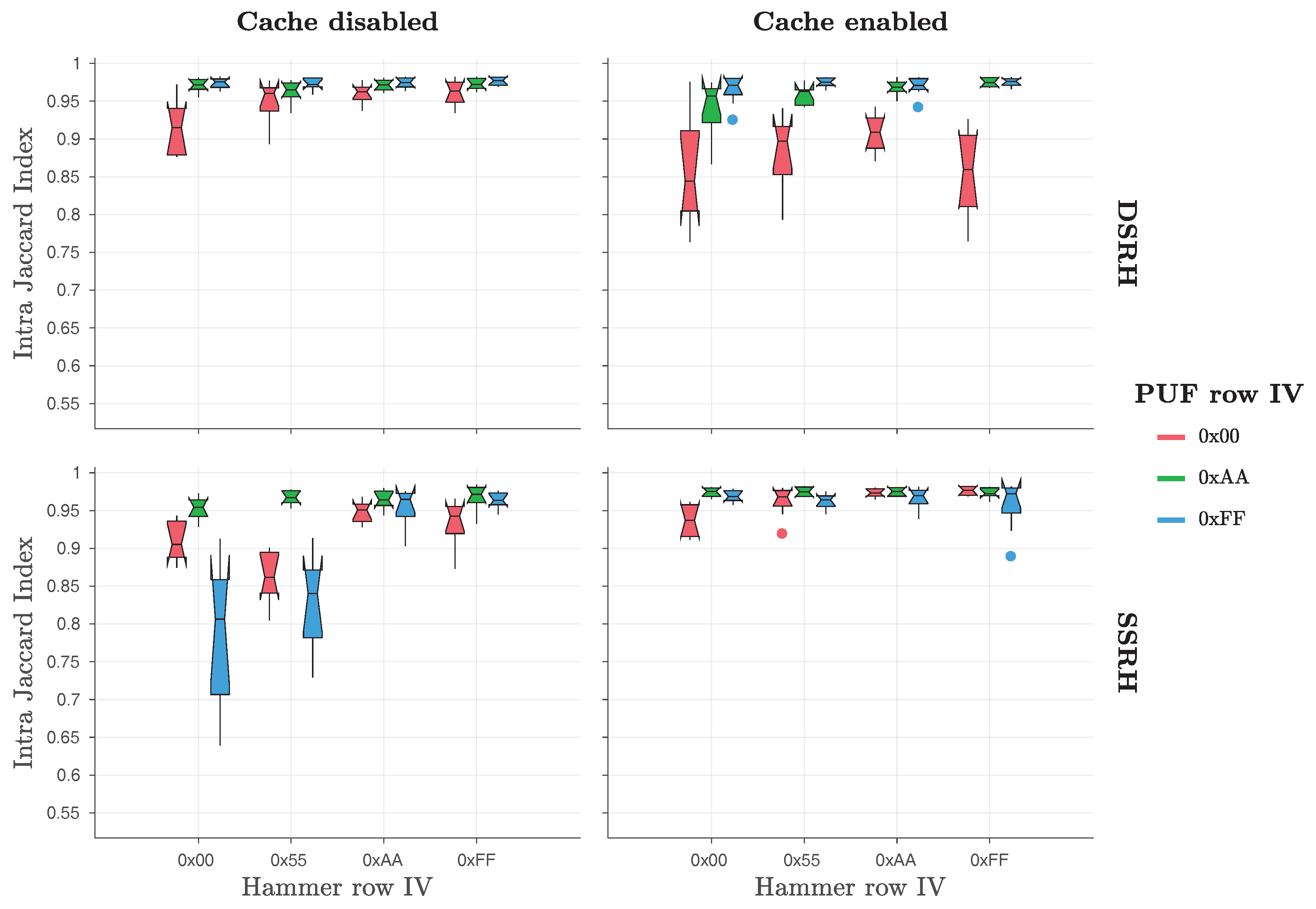
Finally, the original work by Schaller et al. [
1] also considered the Jaccard index [
52] for bit flips found in different responses of the same PandaBoard (intra-device Jaccard index—
) or of different PandaBoards (inter-device Jaccard index—
). By applying these metrics, they were able to prove that the original Row Hammer PUF responses exhibit a high degree of robustness and uniqueness, as the
values were close to one and the
values close to zero. As
Table 2 and
Figure 3 indicate, the original Row Hammer PUF provides the most bit flips and the highest entropy when
hammer row IV = ‘
0xAA’ and
PUF row IV = ‘
0x55’. For this reason, Schaller et al. [
1] chose to present results for the
and the
values only for this case, which can be seen in
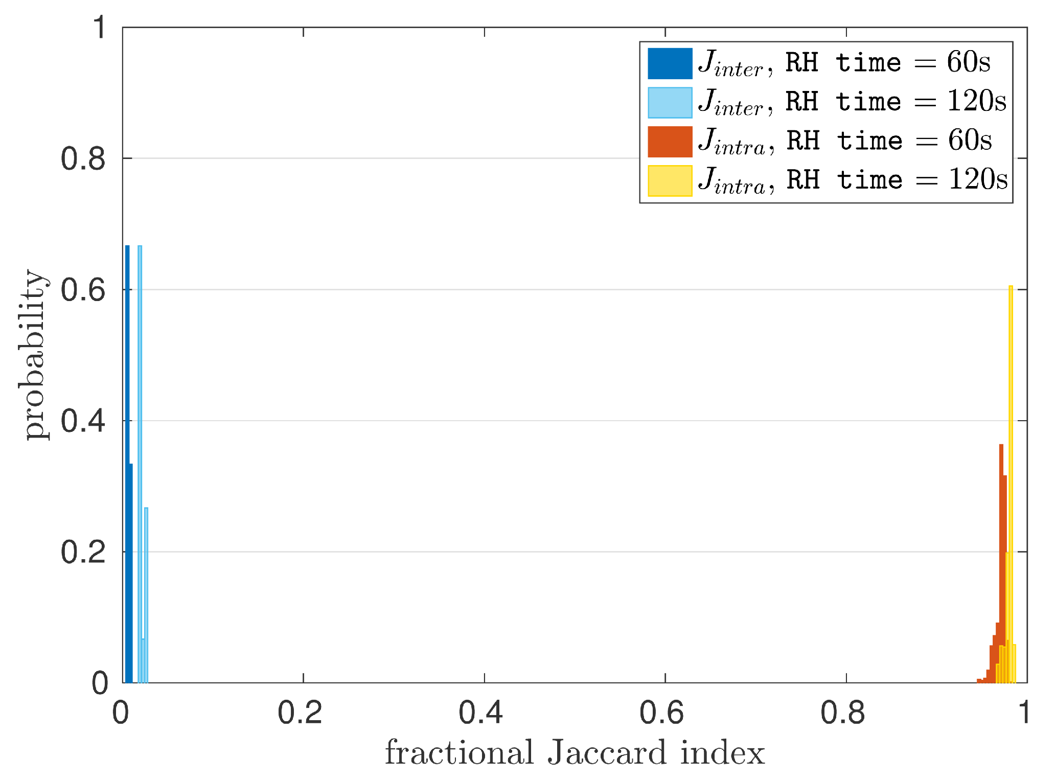
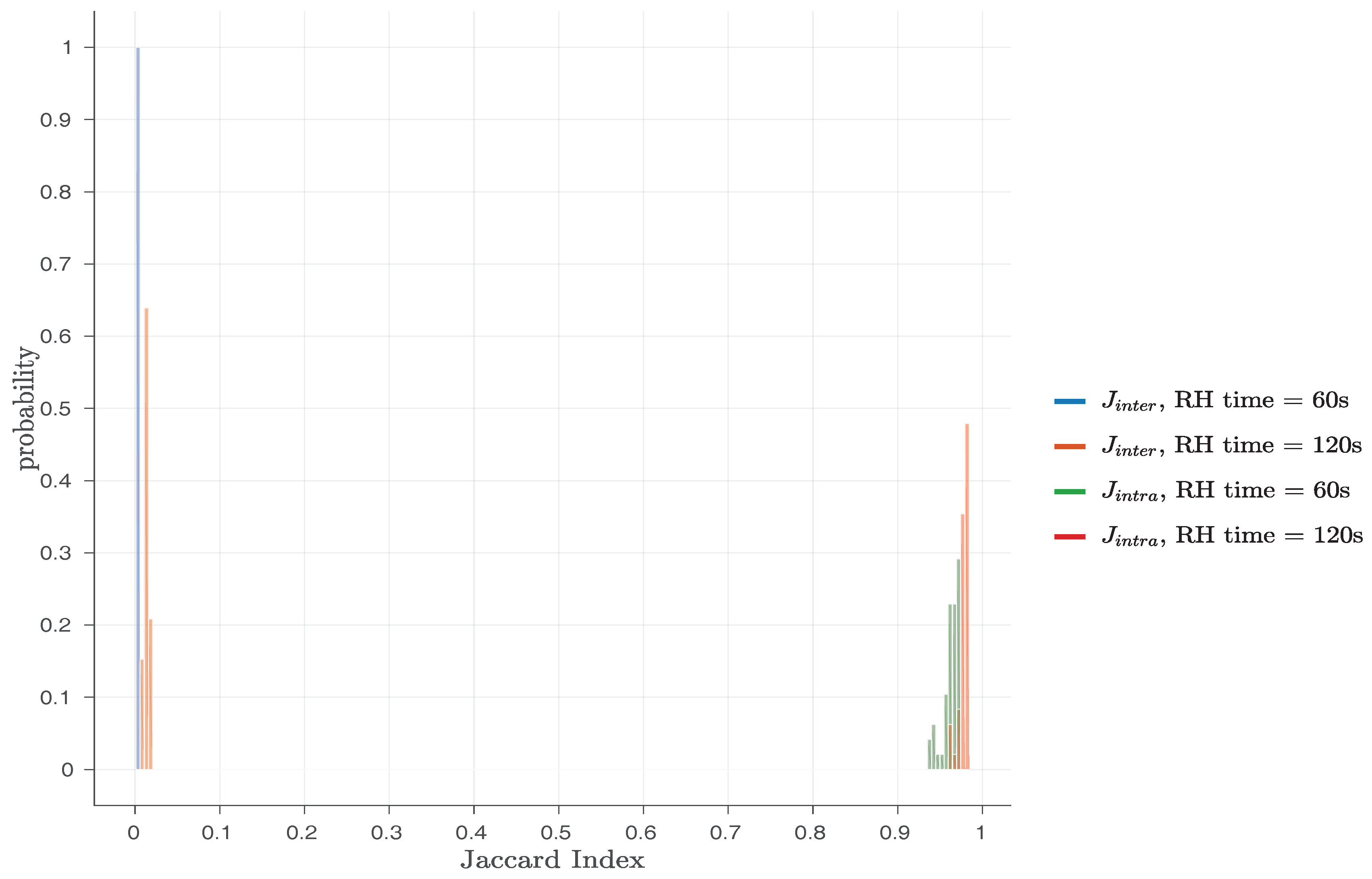
Figure 5.
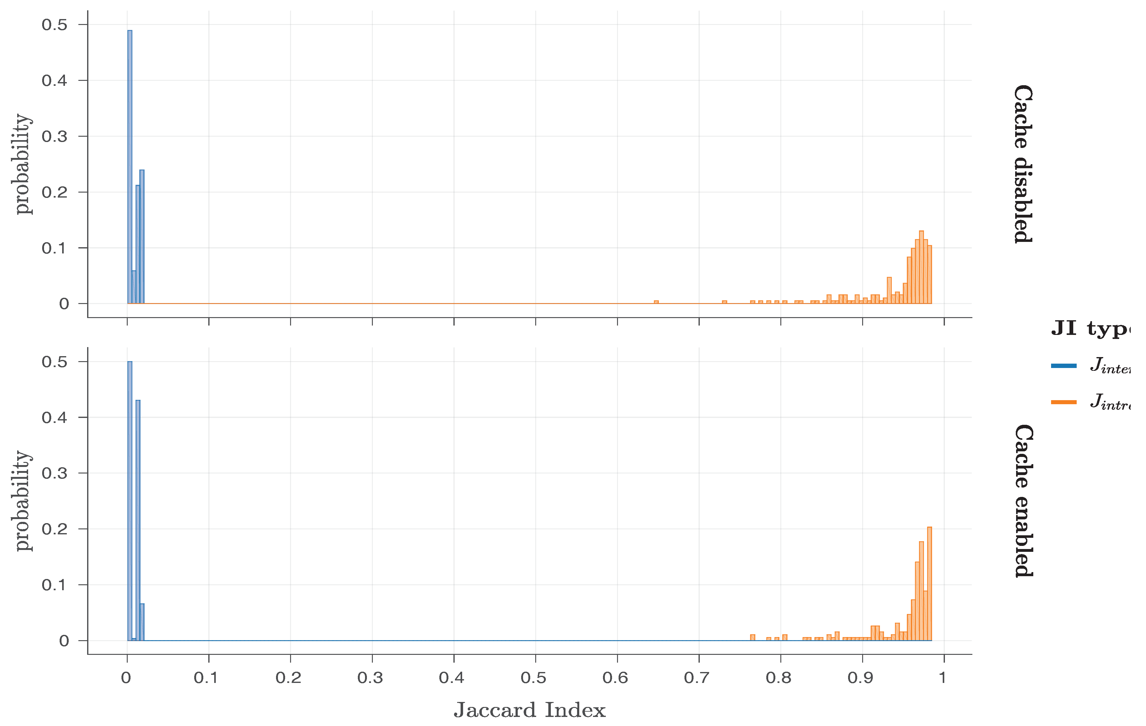
In
Figure 5, histograms for both
and
are presented, for
RH time set either to 60 s or 120 s and
PUF row IV = ‘
0xAA’,
hammer row IV = ‘
0x55’,
PUF size KB and
RH type =
SSRH. This Figure shows that the values of
and
are not overlapping in any case, indicating that all the original Row Hammer PUF instances can be robustly and uniquely identified. With a minimum
value of
, the Row Hammer PUF measurements presented, exhibit a maximum noise of ≈5%, which can be easily corrected by standard Fuzzy Extractor (FE) constructions [
53].
As DRAM retention-based PUFs exhibit high generation times for their responses, providing a relatively low amount of new bit flips over time, they usually exhibit a bias towards their original (non-flipped) values, which may even be public. Therefore, using metrics based on the Hamming distance, such as the intra-device and the inter-device Hamming distances, for their characterisation cannot usually provide useful insights into their performance. However, recent works [
1,
17,
18,
20,
54] have shown that the use of similarly constructed metrics based on the Jaccard index of the positions of their flipped bits, such as the intra-device and inter-device Jaccard index, can provide a clear overview of their performance.
The
and
metrics are based on the
Jaccard index [
52], and for two sets
and
of position indices of flipped bits in two PUF responses
and
, respectively, the Jaccard index between these two responses is given by the formula:
which provides the similarity of the two sets,
and
. If
and
are obtained from the same PUF instance, then
J(
,
) is equivalent to their
value, whereas if
and
are obtained from different PUF instances, then
J(
,
) is equivalent to their
value.
4.5. Extended Investigation of the Role of Temperature on the Responses of the Row Hammer PUF
The original paper by Schaller et al. [
1] recognised that the original Row Hammer PUF responses could be influenced by its
operating temperature. Therefore, it examined the behaviour of the original Row Hammer PUF at different levels of its operating temperature, namely 40
C (working temperature of DRAM on PandaBoard), 50
C and 60
C. Schaller et al. [
1] presented the average number of bit flips and the
values for PUF responses taken at these respective temperatures, as shown in
Table 4.
Nevertheless, the original work by Schaller et al. [
1] does not present any
values calculated for two responses that have been taken at different temperatures from each other. As we will show, this might have been a major shortcoming of this work, as responses taken from the same Row Hammer PUF at different temperatures from each other differ significantly and Row Hammer PUF instances
cannot be robustly and uniquely identified based on them. Nevertheless, as Schaller et al. [
1] indicate, while bit flips increase at higher temperatures, the noise level stays constant at different temperatures,
when the temperature is stable. Therefore, the Row Hammer PUF exhibits sufficient stability to be used at any temperature, within its physical limits,
as long as the temperature remains stable.
Our evaluation results show that even small changes in the
ambient temperature of the Row Hammer PUF can have dramatic effects on its responses. In particular, two responses taken from the same Row Hammer PUF instance at two temperatures differing by only 10
C cannot, in general, be used to identify that instance in a robust way and, sometimes, cannot even be used to uniquely identify such an instance. However, in order to validate that our Row Hammer PUF implementations can be used at different temperatures,
when the temperature remains stable, we utilise the same methodology as Schaller et al. [
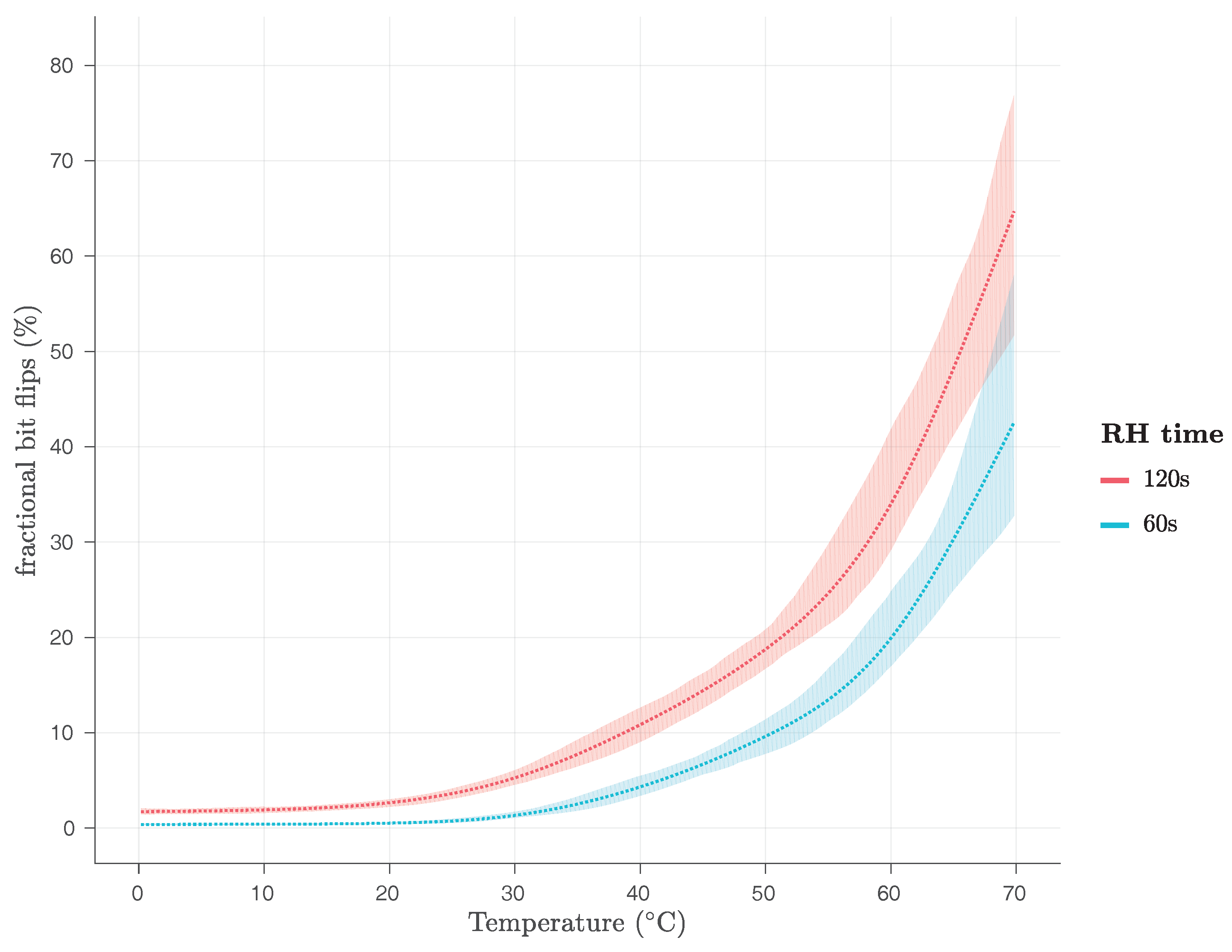
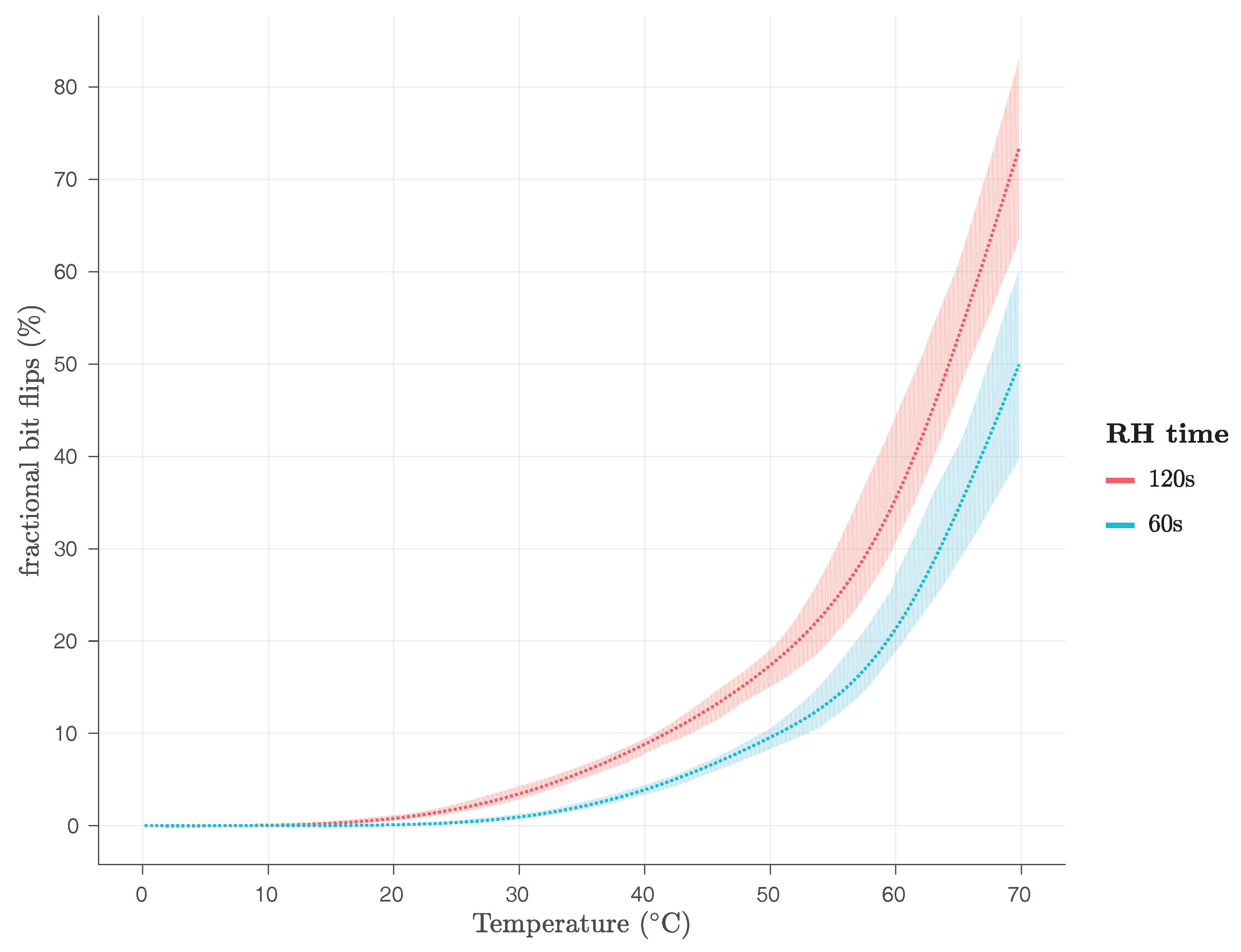
1] and present how temperature variations affect the average fractional number of bit flips observed in the responses of both the firmware, in
Figure 15 and the kernel module implementation, in
Figure 16.
We have evaluated both the firmware and the kernel module Row Hammer PUF implementations in the region from 0 C to 70 C using the ambient temperature and without reading out the exact operating temperature of the DRAM module. We performed our experiments using a climate chamber, namely a Heraeus Vötsch HC4005, which has an absolute accuracy of C. We have also performed experiments for both Row Hammer PUF implementations at 80 C of ambient temperature, at which temperature, however, the PandaBoard becomes unstable and either resets itself or, even, its execution hangs, until the PandaBoard is manually reset.
As
Figure 15 and
Figure 16 show, for
RH time s, the average fractional number of bit flips is close to 0% of the
PUF size for 0
C, for both implementations, and only starts rising after the temperature has risen beyond 20
C, reaching 50% of the
PUF size, for the firmware implementation, and more than 40% of the
PUF size, for the kernel module implementation, at 70
C. As
Figure 15 and
Figure 16 also show, for
RH time s, the average fractional number of bit flips is very close to 0% of the
PUF size, for the kernel module implementation, and slightly above 2% of the
PUF size, for the firmware implementation, for 0
C. The average fractional number of bit flips starts rising slightly before 20
C, for both implementations, reaching more than 60% of the
PUF size, for the firmware implementation, and more than 70% of the
PUF size, for the kernel module implementation, at 70
C.
This is a clear indication that both Row Hammer PUF implementations may face uniqueness problems for low RH time and low temperatures, as not enough bit flips will be occurring, and also for high RH time and high temperatures, as too many bit flips will be occurring, potentially preventing in both cases the correct identification of the PUF instance.
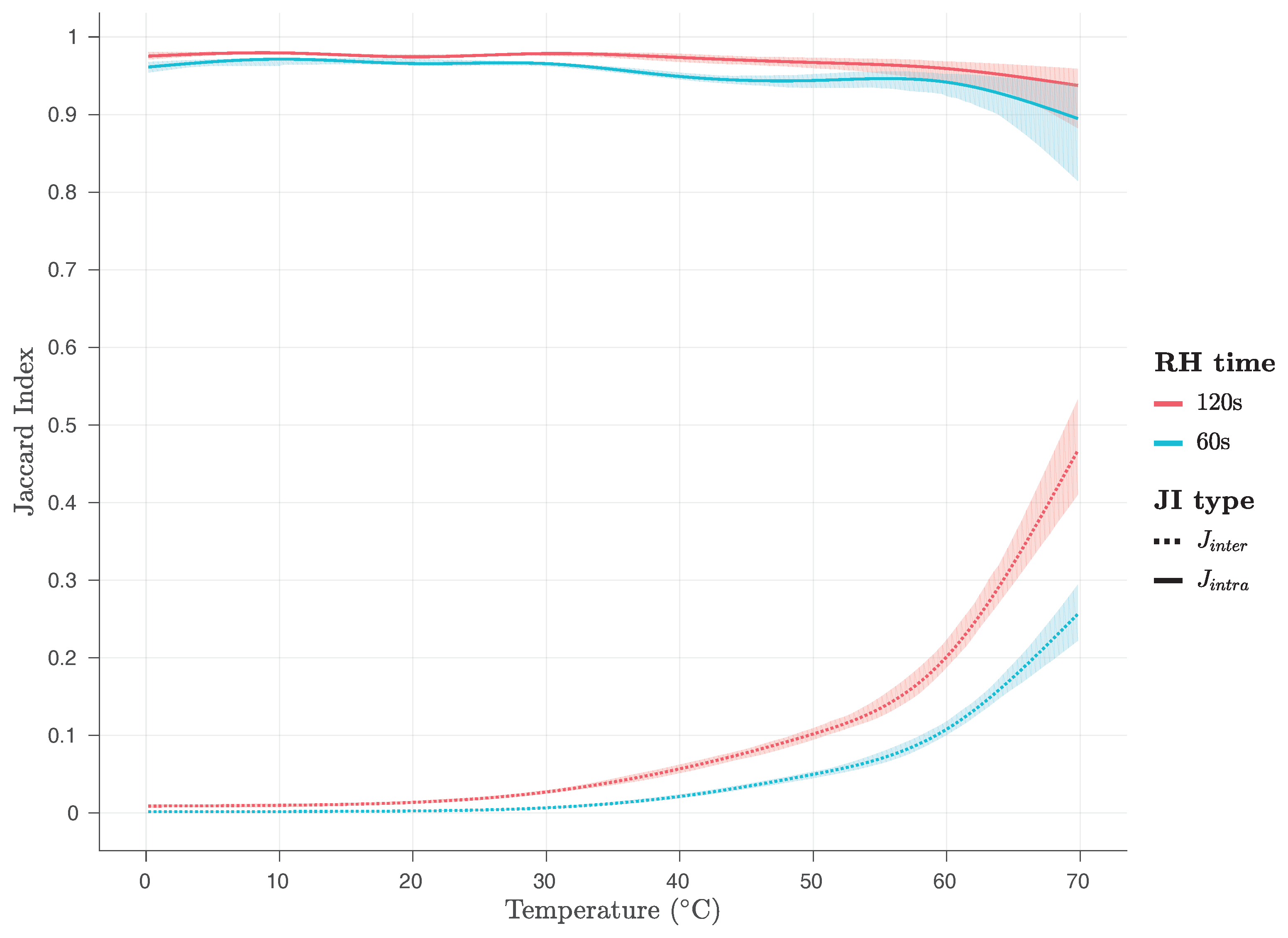
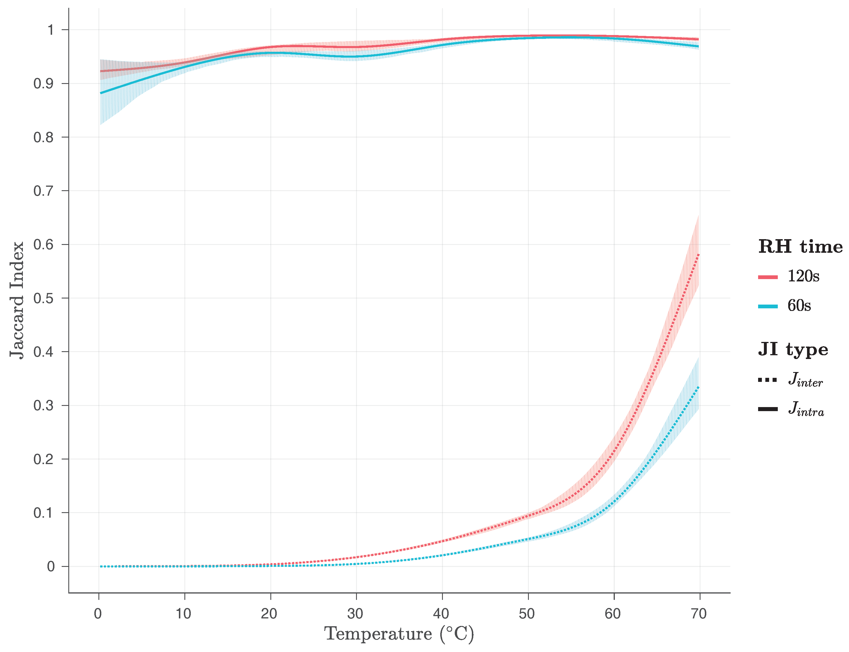
Additionally, we have examined the effects of temperature variations on the
and
values at various temperatures, as shown in
Figure 17 and
Figure 18, for the firmware and the kernel module, respectively. As it can be seen on
Figure 17 and
Figure 18, the values of the
metric are close to 1 for both implementations and all temperatures examined, while the values of the
metric are close to zero for both implementations and temperatures below 60
C, being below 0.1 for temperatures below 50
C, and below 0.2 for temperatures between 50
C and 60
C. However, for temperatures between 60
C and 70
C, they rise abruptly and they reach, for
RH time s, values close to 0.25, for the firmware, and close to 0.35 for the kernel module implementation, and, for
RH time s, values close to 0.45, for the firmware, and close to 0.6 for the kernel module implementation.
This is a clear indication that both Row Hammer PUF implementations may face uniqueness problems for high RH time and high temperatures, as the values reach closer to the ones, surpassing even the value of 0.5, and, therefore, potentially preventing in both cases the correct identification of the PUF instance.
Furthermore, as 20 measurements were performed for each combination of parameters for every 10
C, in the temperature region from 0
C to 70
C, we have utilised an analysis method for the variance of these repeated measurements, based on the work of Bakeman [
55]. We utilise this ANalysis Of VAriance (ANOVA) method, in order to discover the parameters that have the strongest effects on our results. We, therefore, consider only significant and large factor effects as meaningful. Our effect size is calculated as generalized eta-squared (
), based on the work of Bakeman [
55], with values of
denoting strong effects, i.e., factors accounting for more than 26% of the data variance.
Our ANOVA analysis, in general, reveals that indeed temperature has a profound effect on both and values. However, it has a larger effect on the values—with , , , for the firmware, and , , , for the kernel module implementation—than on the values—with , , , for the firmware, and , , , for the kernel module implementation.
Moreover, our results regarding pairwise comparisons for
values, produced using the Student’s
t-tests with pooled standard deviation and adjusted using the Holm–Bonferroni method, reveal significantly lower
p-values for 60
C and 70
C compared to all other groups, for the
values of the responses of both implementations, while
p-values for 50
C compared to groups for 0
C, 10
C, 20
C and 30
C also appear low, for the
values of the responses of both implementations. Furthermore, pairwise comparisons for
values, produced using the Student’s
t-tests with pooled standard deviation and adjusted using the Holm–Bonferroni method, reveal low
p-values for 70
C compared to all other groups, for the
values of the responses of the firmware implementation, and p-values for 0
C and 10
C compared to groups for 20
C, 30
C, 40
C and 50
C, 60
C and 70
C appear low, for the
values of the responses of the kernel module implementation. These results seem to be verified by the appearance and form of
Figure 17 and
Figure 18.
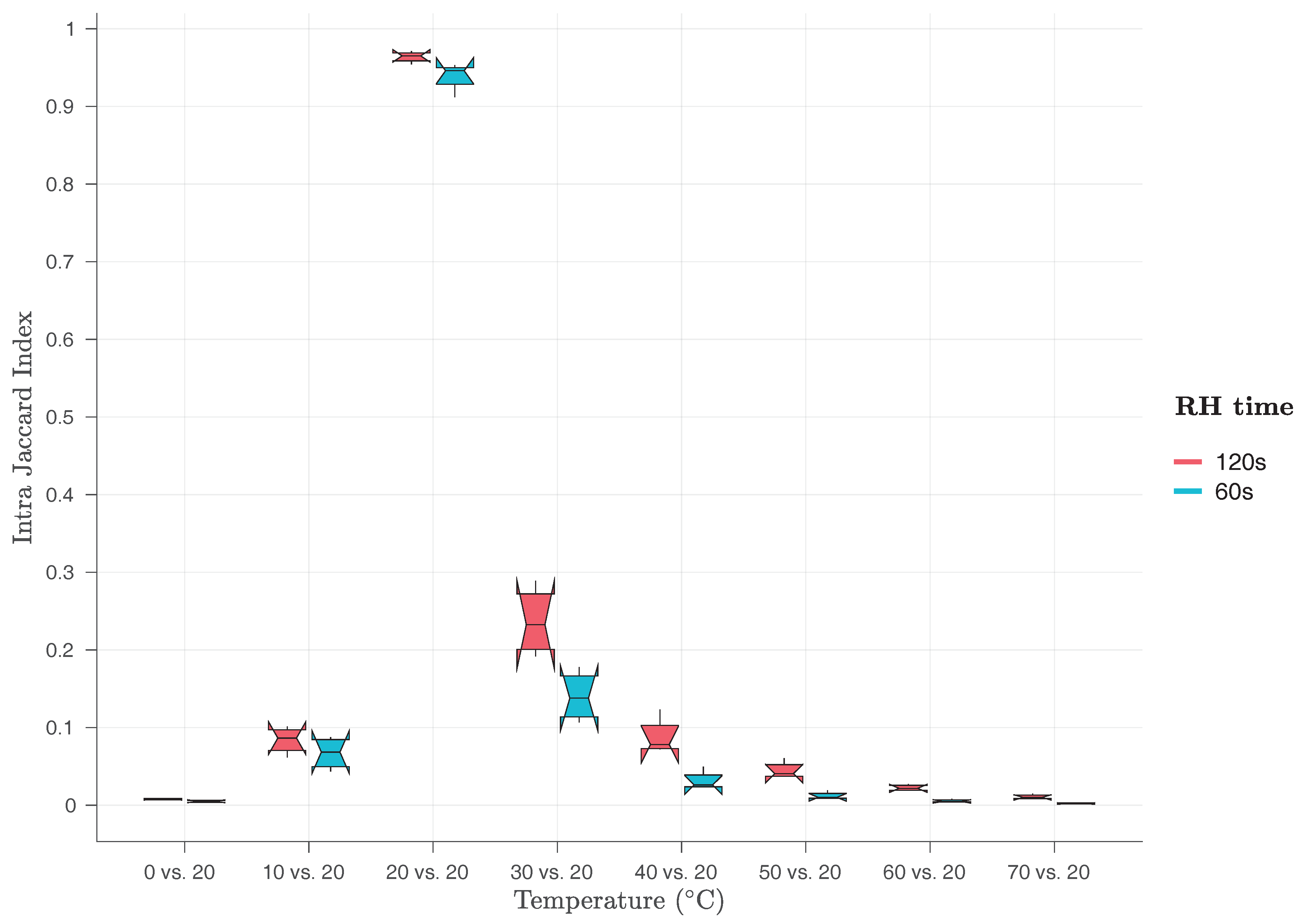
Finally, we have also evaluated, for both implementations, the
for pairs of Row Hammer PUF responses taken at different temperatures from the same device.
Figure 19 presents the
for pairs of responses taken at 20
C and responses taken at the same or different temperatures from each other. As one can see in this Figure, while
values are very close to one for pairs of responses taken both at 20
C,
values for pairs of responses taken at different temperatures from each other are all well below 0.3, indicating that the two responses will rather be recognised as coming from different devices, while in fact they have been produced from the same device. This is a very clear indication that both Row Hammer PUF implementations are facing robustness problems when the ambient temperature changes, even for small temperature variations of 10
C and, therefore, can only be robustly identified when PUF responses taken at the same temperature are used.
As this section shows, temperature can significantly influence the responses of the Row Hammer PUF, affecting both their robustness, in general, as well as their uniqueness, in some cases. We can, therefore, assume that minor variations observed for room temperature measurements could be caused by small variations in the ambient temperature. However, we have also shown that the Row Hammer PUF can be used over a large range of ambient temperature values,
as long as the temperature remains the same. Nevertheless, even in this case, it is uncertain whether it will operate sufficiently at very low temperatures, at which, apart from the long time periods that may be required for responses to be generated, also data remanence effects can start to affect its operation [
56]. As we have discussed uniqueness problems may appear both at very low temperatures for low
RH time, as not enough bit flips may be occurring, and at high temperatures for high
RH time, as too many bit flips may be occurring. In the latter case, we could use the indices of the cells that have not yet flipped, which could provide unique identification of different devices. In conclusion, however, we need to state that the temperature dependency of the Row Hammer PUF is an issue that will need to be adequately addressed, before this PUF can be considered as an efficient security mechanism for widespread usage. We do need to note that our experiments were based on different values of the
ambient temperature, a characteristic that an attacker can very easily manipulate, and not on the
operating temperature of the PUF itself.
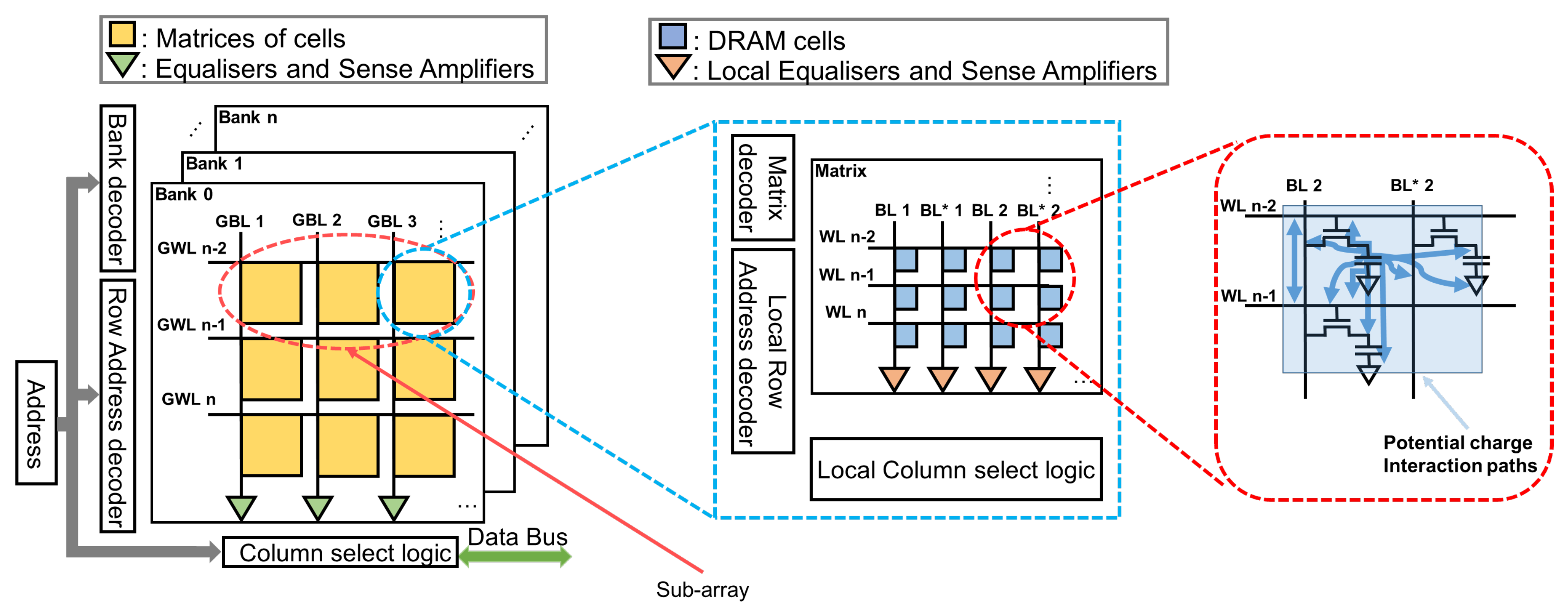
4.6. Potential Statistical Relations among PUF Cells
In this section, we examine whether there is some statistical relation between the PUF cells that flip and their neighbourhood. We examine whether there is a statistical relation between PUF cells that have flipped and the values of their neighbouring PUF cells and also whether there is a statistical relation between PUF cells that have flipped and other PUF cells in their neighbourhood that also flip for the same or a lower RH time value. In particular, we examine the probability that PUF cells nearby a bit flip have a specific value and the probability that such cells have flipped at the same or a lower RH time value. If any of these probabilities are significantly higher than the relevant average probability for all the PUF cells, then we can conclude that some statistical relation exists. Otherwise, we can conclude that no statistical relation seems to exist among the PUF cells that flip and their neighbouring PUF cells.
In this way, we can investigate whether there is some way to predict the positions of the bit flips or if they appear to be random. If the positions of the bit flips could be predicted, then a number of different attacks taking advantage of this property may have been possible. However, in all cases, our results show that there appears to be no statistical relation between the PUF cells that flip and their neighbourhood. Nevertheless, a more in-depth investigation would be required, before we could state with absolute certainty that such a relation does not exist.
First, we examine the average values of PUF cells around a PUF cell that has flipped, for room temperature,
PUF size KB,
RH time s,
hammer row IV = ‘
0x55’ and
PUF row IV = ‘
0xAA’ and all the different combinations of cache states and
RH type, as shown in
Table 5 and
Table 6, for the firmware and the kernel module implementation, respectively. In this way, we can detect potential statistical relations affecting the response of the PUF that stem from interactions between the charge that was stored in a PUF cell that has flipped, i.e., that has had at least half of its charge leaked, and the charge stored in other PUF cells found in different rows and columns of the DRAM around the flipped PUF cell. We do so by using a
window having the flipped PUF cell in its centre every time. Of course, only cells in the same row of this window are adjacent to each other in the DRAM module, as PUF cells in different rows may be separated by a hammer row in the DRAM module. Our results, which are shown in
Table 5 and
Table 6, indicate that the average probability of a neighbouring PUF cell having a logical value of one or zero is close to 50% in all cases, suggesting a lack of any statistical relation between these values and the fact that the center cell of the window has flipped. We test for
RH time s only, as the PUF cells that have flipped for
RH time s are a subset of the PUF cells that have flipped for
RH time s.
Subsequently, we examine the average probability that a PUF cell has flipped in the neighbourhood of another PUF cell that has flipped, for room temperature,
PUF size KB,
RH time s,
hammer row IV = ‘
0x55’ and
PUF row IV = ‘
0xAA’ and all the different combinations of cache states and
RH type, as shown in
Table 7 and
Table 8, for the firmware and the kernel module implementation, respectively. In this way, we can detect potential statistical relations affecting the response of the PUF that stem from interactions between the charge that was stored in a PUF cell that has flipped, i.e., that has had at least half of its charge leaked, and the charge of other PUF cells found in different rows and columns of the DRAM in an extensive region around the flipped PUF cell, leading these other PUF cells to decay faster than usual, and, therefore, also be flipped. We do so by using a
window having the flipped PUF cell in its centre every time. Of course, only cells in the same row of this window are adjacent to each other in the DRAM module, as PUF cells in different rows may be separated by a hammer row in the DRAM module. Our results, which are shown in
Table 7 and
Table 8, indicate that the average probability of a PUF cell being flipped in the extended neighbourhood considered is consistently similar to the general probability of a PUF cell being flipped at
RH time s, for each case, as shown in
Figure 6 and
Figure 7, for the firmware and the kernel module implementation, respectively. Therefore, our results suggest a lack of any statistical relation between PUF cells that flip within a particular
RH time. We test for
RH time s only, as the PUF cells that have flipped for
RH time s are a subset of the PUF cells that have flipped for
RH time s.
Finally, we also examine the average probability that a PUF cell that has flipped within
RH time s is in the neighbourhood of another PUF cell that has flipped within
RH time s, for room temperature,
PUF size KB,
hammer row IV = ‘
0x55’ and
PUF row IV = ‘
0xAA’ and all the different combinations of cache states and
RH type, as shown in
Table 9 and
Table 10, for the firmware and the kernel module implementation, respectively. In this way, we can detect potential statistical relations affecting the response of the PUF that stem from interactions between the charge that was stored in a PUF cell that has flipped, i.e., that has had at least half of its charge leaked, within
RH time s and the charge of other PUF cells, found in different rows and columns of the DRAM in an extensive region around the flipped PUF cell, that have flipped, i.e., that have had at least half of its charge leaked, within
RH time s and, therefore, may have also affected the decay of the PUF cell that has flipped within
RH time s. We do so by using a
window having the PUF cells that flip within
RH time s in its centre every time. Of course, only cells in the same row of this window are adjacent to each other in the DRAM module, as PUF cells in different rows may be separated by a hammer row in the DRAM module. Our results, which are shown in
Table 9 and
Table 10, indicate that the average probability of a PUF cell having flipped within
RH time s and at the same time being in the neighbourhood of another PUF cell that has flipped within
RH time s is consistently similar to the general probability of a PUF cell being flipped at
RH time s, for each case, as shown in
Figure 6 and
Figure 7, for the firmware and the kernel module implementation, respectively. Therefore, our results suggest a lack of any statistical relation between PUF cells that flip at a particular
RH time and PUF cells that flip at another particular
RH time , with
.
Thus, our results indicate that the logical values—and, therefore, also the charges—and the retention times of victim cells in a DRAM utilised for the implementation of the Row Hammer PUF do not affect the retention times of other victim cells in that DRAM, while it is being employed as a Row Hammer PUF implementation, as the logical values and retention times of PUF cells around a PUF cell that has flipped appear to be random. Additionally, the position of new bit flips does not appear to be based on the position of bit flips that have already occurred. Our results do not indicate any statistical relation of any sort, including a potential clustering of the bit flips. We chose to examine the logical values of cells neighbouring a PUF cell that has flipped using a window, as these values are also based on the PUF row IV, and it would be easy to detect potential statistical relations, while we used a more extensive window to examine the probability of PUF cells in their neighbourhood of a PUF cell that has flipped, flip within the same or a lower RH time value, because leakage paths and charge interactions within the DRAM module could potentially be occurring within an broad range around the cell that has flipped and is placed in the centre of the window.
We need to note here that the disturbance errors that result in the observed bit flips are, of course, clustered in the DRAM region being used for the implementation of the Row Hammer PUF. In this section, we examine whether, within this region, the observed bit flips appear to be clustered in particular sub-regions and whether some statistical relation appears to be present between the bit flips observed in the PUF responses and their neighbouring PUF cells.
4.8. Potential for Commercial Adoption
As the previous sections indicate, although the Row Hammer PUF seems to be strongly dependent on temperature, its responses are, in general, unique, robust and of high entropy. Nevertheless, as temperature variations can significantly affect the robustness of the Row Hammer PUF responses, future research will need to fully address this issue.
It should also be noted that the dependency of the Row Hammer PUF on temperature makes it, in general, susceptible to Denial of Service (DoS) attacks, as an attacker could change the ambient temperature and, in this way, also change the PUF response. Additionally, in case the ambient temperature is very low or very high, the PUF response could be guessed or brute-forced, as the number of bit flips observed in it could be either too low or too high, respectively. Nevertheless, this latter attack also depends on whether an attacker may know the PUF row IV.
A proposed way to address the dependency of the Row Hammer PUF on temperature is to examine the effects of temperature on the PUF responses in detail, in order to identify a measurement time at each particular temperature, such that each of these times will result in a similar PUF response being acquired [
17,
18]. In this way, by using a set of equivalent RH time, one for each particular temperature, in order to acquire similar responses at each temperature, the Row Hammer PUF implementations can provide robust PUF responses even at different temperatures. However, such a solution may still suffer from high response generation times, at rather low temperatures.
Another potential way to address the effects of temperature on the Row Hammer PUF responses would be to combine these responses with the temperature of the PUF module. In particular, as the PandaBoard’s microprocessor module, which contains its on-board DRAM package, also contains a temperature sensor, it is possible to combine temperature readings with the current temperature of the DRAM module. Preliminary experiments have indicated that the proposed solution can indeed provide results that appear to be highly promising. However, whether this potential solution can be used to solve the aforementioned issue in an efficient way remains in the scope of a future work. Nevertheless, such a solution can also be utilised in order to stabilise the PUF responses of DRAM retention-based PUFs, in general, as their implementations seem to suffer from such temperature dependencies [
17,
18,
20].
In the worst case, a trivial solution can be employed, by examining the responses of the Row Hammer PUF at intervals of C for every RH time that will be used. In this way, the responses of the Row Hammer PUF could be used for identification and authentication purposes, as long as also the temperature at which they have been taken is also reported.
Therefore, as the effects of temperature variations on the Row Hammer PUF can either be controlled or mitigated, its PUF responses could be considered as unique per PUF instance, mostly robust and, in general, of high entropy. In particular, as our room temperature experiments indicate, if the temperature remains relatively stable, PUF responses are highly stable and unique, with measured and values being, in all cases, close to zero and one, respectively.
Moreover, the Row Hammer PUF also offers a number of further advantages in comparison to other PUFs. Firstly, it can be implemented in most contemporary computer systems, as DRAM is an inherent component of them. Secondly, it offers multiple Challenge–Response Pairs (CRPs) and can be accessed at run-time, in contrast to the SRAM PUF that provides only a single CRP and can only be accessed at boot-time. Additionally, it can provide significantly lower generation times and higher entropy than similar DRAM retention-based PUFs, while also allowing for the implementation of the same cryptographic protocols as the ones implemented using those exact DRAM retention-based PUFs, such as key agreement [
17] and authentication [
17,
18] protocols that have been implemented using the exact same hardware.
Furthermore, all of its current implementations require administrative rights to be properly inserted into a system and executed, which could prevent a number of attacks against them. Nevertheless, we note that security is a
relative term, being highly dependent on the manufacturing costs, the costs of performing a successful attack and the potential gains/damages of such an attack [
57].
Therefore, the Row Hammer PUF, like any other security mechanism [
57], cannot provide perfect security, even if its PUF responses are no longer affected by temperature variations. Thus, in order to assess its value as a security mechanism and, in this way, also determine its potential for commercial adoption, we should examine its manufacturing costs, the lowest cost of a successful attack and the potential gains/damages of such an attack.
However, we already know that the manufacturing costs of the Row Hammer PUF are minimal for most contemporary computer system implementation, as DRAMs are inherent components of them. We also have discussed that the easiest way to attack the Row Hammer PUF is by changing the ambient temperature and that such an attack can either cause a DoS or, more rarely, lead to the PUF response becoming quite easy to reveal.
Hence, we can easily conclude that Row Hammer PUF implementations, and especially the kernel module one, are implementing a flexible, lightweight, cost-efficient and practical security primitive that can be used as a basis for the realisation of cryptographic applications, especially in low-end COTS devices, such as IoT hardware, that have limited resources and cannot support more complex security mechanisms, such as TPMs. Nevertheless, this security primitive suffers a significant vulnerability in the form of its strong dependency to temperature variations, which would prevent its commercial adoption for practical applications, until it has been sufficiently addressed.
Finally, we need to also note that our Row Hammer PUF implementations could require slight modifications in order to be applied on different devices. We note here that as the internal die architecture of a DRAM is usually not known and address scrambling may be employed, as well as row redundancy, adequate testing, employing the techniques discussed in [
30], may be required in order to achieve effective row hammering. Nevertheless, as long as the row hammer effect significantly affects the DRAM of a device and the functionality of its DRAM controller can be controlled and modified through software, we believe that the Row Hammer PUF can be implemented in such a device. We clarify here that for the proper implementation of the Row Hammer PUF on a device, this device must have a DRAM module that is susceptible to the row hammer effect and software code running with administrative privileges must be able to control the refresh operation, the ECC and the caching of at least a single DRAM region with a size of several KB. As these criteria seem to be fulfilled by a large number of, even resource-constrained, devices, we believe that the Row Hammer PUF could potentially be used in order to provide run-time cryptography and improved security in devices that cannot support other more resource-demanding security mechanisms.

 ,
, 


