
A Delay-Based Machine Learning Model for DMA Attack Mitigation †


Electrical and Computer Engineering, University of North Carolina at Charlotte, Charlotte, NC 28223, USA
*
Authors to whom correspondence should be addressed.
†
This is an extended conference version that was presented at 22nd International Symposium on Quality Electronic Design (ISQED 2021).
Cryptography 2021, 5(3), 18; https://0-doi-org.brum.beds.ac.uk/10.3390/cryptography5030018
Submission received: 9 June 2021
/
Revised: 8 July 2021
/
Accepted: 21 July 2021
/
Published: 27 July 2021
(This article belongs to the Special Issue Cybersecurity, Cryptography, and Machine Learning)
Abstract
:Direct Memory Access (DMA) is a state-of-the-art technique to optimize the speed of memory access and to efficiently use processing power during data transfers between the main system and a peripheral device. However, this advanced feature opens security vulnerabilities of access compromise and to manipulate the main memory of the victim host machine. The paper outlines a lightweight process that creates resilience against DMA attacks minimal modification to the configuration of the DMA protocol. The proposed scheme performs device identification of the trusted PCIe devices that have DMA capabilities and constructs a database of profiling time to authenticate the trusted devices before they can access the system. The results show that the proposed scheme generates a unique identifier for trusted devices and authenticates the devices. Furthermore, a machine learning–based real-time authentication scheme is proposed that enables runtime authentication and share the results of the time required for training and respective accuracy.
1. Introduction
The traditional data transfer between a host system’s main memory and an external device is controlled by the central processing unit (CPU) and is used by the programmed input/output or interrupt-driven I/O. The basic process of the data transfer goes through the CPU and then transferred to the appropriate destination. With large transfers, the CPU gets significant drops in performance. The DMA directly accesses the main memory and bypass the CPU all together, to reduce the impact of data transfers on performance. During the DMA process, CPU initiates the data transfers, and the remaining process of data transfer is handled by the DMA. The DMA is supported by the new architectures and provide an interface and supports across multiple data buses such as Industry Standard Architecture (ISA) and Peripheral Component Interconnect Express (PCIe).
With the advancements of technology and architecture, there are several new threats to the security of hardware such as direct attacks and side channel attacks. One way to deal with direct attacks is to use secure processor architectures, where encrypted data is sent to a secure processor to compute the data in a tamper-proof, authenticated environment [1,2]. When it comes to side channel attacks, however, this method has been known to vulnerabilities, one of which is using an older, compromised Operating System [3]. While a different set of security schemes are used to protect against direct attacks, side channel attacks still pose a challenge to the security and privacy of users. When an attacker uses a compromised DMA-supported device, the attacker can use the device to give them direct access to the memory and allow them to read the entire memory or even download their own data into the system. To mitigate the attacker’s access to the main memory with DMA attacks, there has been recent work that uses key-based authentication as well as memory virtualization [4,5].
Authentication refers to verifying that a user or a component has the permission to access and use the host system. One form of authentication is to use a special key that is unique to the user or component to identify them. One such key authentication architecture is a Public Key Infrastructure (PKI). A PKI assigns a public and private key pair used to identify them where the certificate is used to guarantee the public key is assigned to the given user [6,7].
While studies look promising, such methods can be expensive or altogether not possible for regular consumer grade computers. Direct access data transfer is vulnerable even with security measures such as discussed in [8,9]. PKI has known vulnerabilities of side channel attacks, specifically power consumption analysis [7]. We propose a hardware-based embedded unique identifier generation process using profile time for the authentication process to enable secure DMA connection to mitigate such attacks and to detect if the device has been tampered.
Furthermore, state-of-the-art artificial intelligence algorithms are investigated to tackle a real time authentication process [10]. Deep learning, a class of artificial intelligence including Convolutional Neural Networks, Multilayer perceptron networks, Decision Tree Classifier, and Random Forest, is used as different machine learning models for the authentication process. All these networks have been built using the Scikit-learn and the Keras API [11,12].
In this work, we propose a lightweight authentication scheme for PCIe devices based on device profiling. As per the authors knowledge, there have been no publicly reported studies that have used profiling time to create a database for authentication of PCIe devices to prevent DMA attacks.
Contribution: This paper makes the following contributions:
- We propose a novel scheme for DMA attack mitigation, using the profiling time of the devices in order to generate unique identifiers and create a database of trusted devices on the host machine and design an on-the-fly authentication process.
- Machine learning techniques are proposed and compared for the authentication process based on the neural network, decision trees, random forest, and multilayer perceptron.
- The results discuss a comparative analysis on the time required for training and the accuracy based on different machine learning models that are suitable for the runtime needs of PCIe device authentication.
2. Related Works
2.1. Direct Memory Access (DMA)
Traditional systems heavily rely on the CPU and utilizes several cycles for data transfers between peripheral devices and the main memory. The CPU requires every block of data to be read and passed through it, resulting in using significant resources and slowdown of the overall performance. A way to get around this performance overhead is to use DMA, which allows the peripheral hardware to bypass the CPU and directly send and receive data from the memory as well as read and write from the memory. DMA allows the interactions between external devices and memory independent of the CPU; therefore, the load of CPU is reduced, and this improves the overall performance of the system.
The DMA is supported by several bus architectures, such as Industry Standard Architecture (ISA), Advanced Microcontroller Bus Architecture (AMBA), and Peripheral Component Interconnect (PCI). DMA allows the processor of a system to run more efficiently using the Direct Memory Access (DMA) controller. The DMA controller transmits data from one part of the system to another. The DMA is connected to different components of the system through different buses and channels. During the initialization of the DMA controller, the memory controller provides memory addresses and initiates memory read or write cycles for data transfer and sends an interrupt to the CPU when the whole process of data transmission is done.
2.2. Composition of DMA
2.2.1. DMA Controller
The DMA controller is a control unit located on the I/O interface circuit of the host machine. For example, Intel 8237 is a four-channel DMA controller that allows four devices to store their DMA information in the controller at the same time [13]. The controller holds information about the DMA transfer, such as the direction, the memory address, and the size of the transfer. It also contains a counter that tracks the status of ongoing transfers. When the controller receives a DMA request signal, it gains control of the bus and drives the signal lines so that the device can read or write its data. [14]
2.2.2. DMA Memory Access Protocol
The PCI/PCIe device once connected/powered remains inactive and only responds to configuration transactions that is reading vendor ID, device ID, etc. During the booting process, the BIOS/kernel offers access to the PCI/PCIe device, then allocates address space and I/O regions for each device. By the time a device driver accesses the device, the memory and I/O regions for this device is mapped into the CPU’s address space. [15]
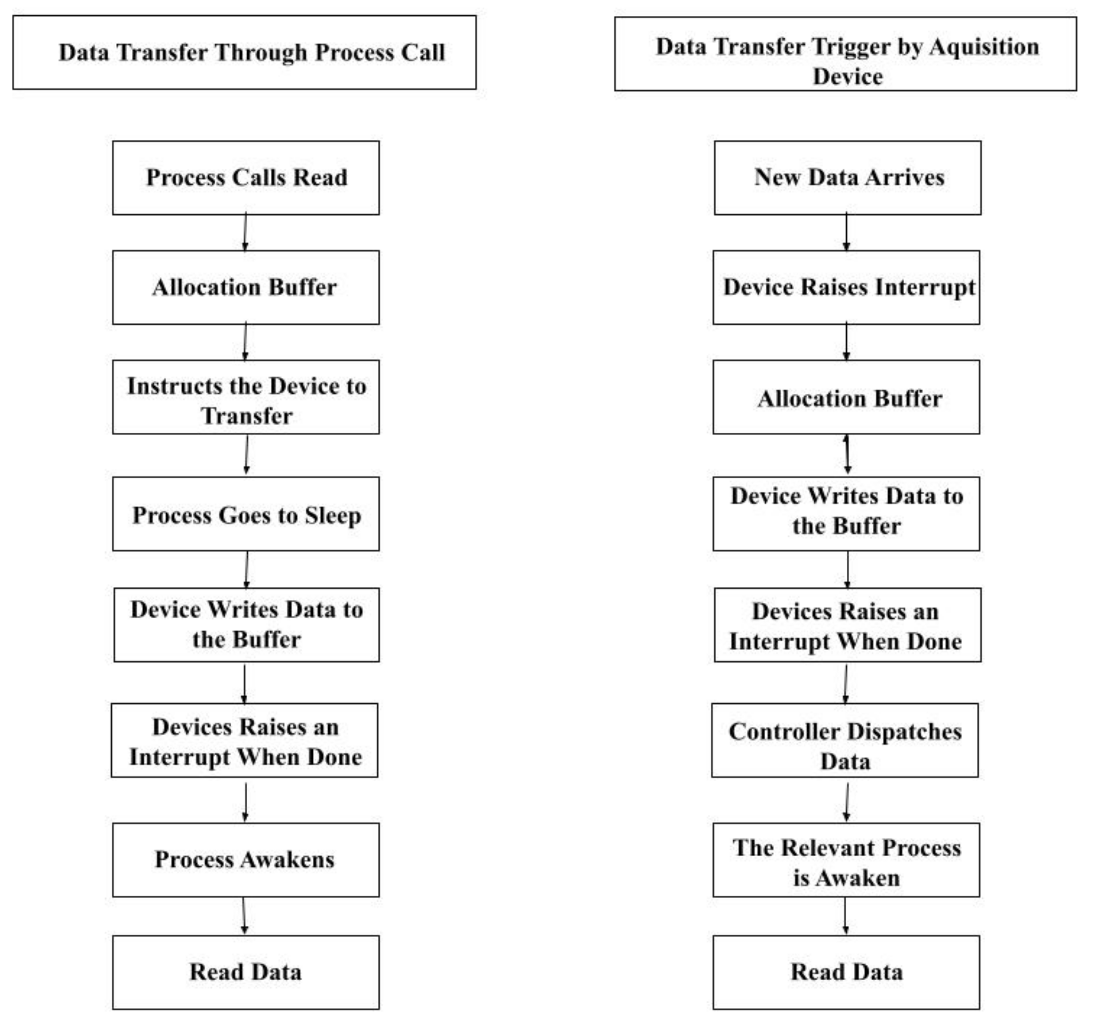
DMA supports two different types of data transfer between the device and the host machine. As shown in Figure 1, the left flowchart describes the process triggered by the process call, and the right one describes the process of data transfer triggered by data acquisition devices. The process of allocating a DMA buffer and generating an address for that buffer that is accessible by the device is realized by using dma_alloc_coherent and dma_free_coherent (coherent DMA mapping, uses a coherent buffer that is available to both the CPU and the peripheral) or dma_map_single and dma_unmap_single (streaming mapping, usually set up for a single operation).
2.2.3. Root Complex
The root complex of a PCIe device connects the PCIe device tree to the RAM and the CPU as well as provide a high-speed connection to the GPU [16]. The root complex is usually implemented in the northbridge/host bridge of the systems CPU. The PCIe device tree has a logical port called the root port that connects to the root complex and can be physically implemented on a chip that is not the same chip that resides in the root complex [16]. Sometimes, a device could have multiple root ports, so a switch is needed for the root complex to choose the correct root port needed in such scenario.
The root complex translates the CPU commands sent to the PCI device and serves as mediator between the CPU and device. For example, the CPU-read transaction command to the PCIe, is interpreted by the root complex to recognize the task as memory read transaction and translates it into a PCIe-read Transaction Layer Packet TLP [16]. It is ultimately the root complex of the PCIe device that can access the main memory, and controls the addresses it can use.
2.2.4. PCI/PCIE Device
Configuration Space: Figure 2 shows the configuration that includes vendor ID and device ID, for the identification of the PCIe device, where Subsystem vendor ID and subsystem device ID are used to differentiate similar devices.
Registering PCI/PCIe Drivers: The structure of a PCI driver is the struct pci_driver structure that consists of several function callbacks and variables to describe the PCI driver to the PCI core.
2.3. DMA Attack
DMA improves the overall transfer by freeing up the CPU cycles from data transfer between the main memory and external devices. However, the native feature of direct access also brings potential risks of security breaches. As a type of side-channel attack, the DMA compromise has been proved as a powerful and efficient attack that allows the attacker to read and write the memory on the victim system directly. A DMA attack is a hardware vulnerability; in the case of Firewire vulnerability, an attacker accessed the memory through the DMA controller on a Windows 7 OS, and was shown to work as well on other operating systems [17].
Ref. [18] demonstrated a DMA attack named PCILeech which allows the attacker to read/write the memory once the peripheral PCIe device is connected to the victim system without the need for hardware drivers. Such attacks include the unauthorized user bypass the logon password requirement, load drivers to the system, execute code on the system, and even create system shells [4]. PCILeech can run on a wide variety of different hardware and can run on Windows and Linux operating systems. Ref. [19] demonstrates privacy leakage from the main memory using the Montgomery’s ladder technique to send a 128-byte message with a 64-byte secret exponent, where the PCILeech can obtain all the secret bits.
The same year, the Intel Advanced Threat Research team performed a DMA attack over the air by modifying a WiGig dock to compromise a laptop that is connected to the dock wirelessly [20]. The architecture of wireless connection allows the attacker to use the DMA capabilities to dump secrets out of the memory on the victim machine remotely. The work reported in [9] shows the Thunderbolt protocol with access-control enabled is not resilient to DMA attacks. The attacker-controlled device obtains full access to the main memory successfully via a Thunderbolt port by identity clone and spoofing.
2.4. DMA Attack Mitigation
The technique to mitigate the risk of DMA attacks such as BitLocker, was first introduced in Windows Vista, where Microsoft provides pre-boot authentication to enhance data privacy. Bitlocker performs a full-disk encryption to secure the data, where the keys can be securely generated an stored on Trusted Platform Module (TPM) [21]. This method can also be used in pre-boot authentication, where the user once provides the correct identifier, that can be a specific pin or a USB startup key, BitLocker accesses the encryption key and store it into the memory. One of the problems with BitLocker is that it can only do encryption for hard drives or removable data drives and the memory can still be comprised by a DMA attack once the booting process for the system is complete. Another issue is that the encryption and decryption processes have a very high time overhead.
In version 1709 of Windows 10, Microsoft added a new feature where the PCI/PCIe ports that were hot-pluggable were blocked from the main system until a registered user signed on [4]. This feature makes sure that attacks using a compromised PCI/PCIe device are denied to the keys generated by BitLocker. The problem with this approach is that if the system remains locked then the user is unable to use the PCI/PCIe.
Another technique that is used to reduce the risk of a DMA attack is called VT-d by Intel and AMD-Vi by AMD, but is generally known as Input-Output Memory Management Unit (IOMMU) [5,22]. IOMMU connects the Direct Memory Access bus and the main memory together and translates the IO virtual address to physical address. With this function activated, the IOMMU grants each DMA access to only certain parts of the memory, so if one device is compromised it does not put the whole memory at risk. While this method does reduce the risk of a DMA attack it fails to protect the memory when the system has a smaller memory size.
One hardware that is being looked at to help with DMA attacks is oblivious RAM (ORAM). In a conceptual sense, ORAM maintains memory, encrypts it, and when the memory is read, it reshuffles the memory [23]. Because of this feature, it has been seen in more recent models and plans for securing devices. There are still some problems with this form of hardware though, the main problems are that the timing protection causes extra overhead and if an attacker gains access, it could cause the hardware to leak privacy.
Access control is also another strategy to mitigate the DMA attacks and a way to employ is with either encryption-based authentication or to use a Trust-On-First-Use (TOFU) scheme [24]. Each component and the host system can have a key-based citification authentication architecture. However, such schemes are costly as all the components must be authenticatable at any time. With a TOFU scheme, when a trusted device is connected to the host machine for the first time, the system records the device with a unique identifier and stores it in a database of trusted devices on the machine. With this method, any device that is not within the database of trusted devices will be blocked from the system. However, when it comes to PCIe devices, unique identifiers are not generated for them during their authentication. Vendor ID, device ID, and the ID of the PCIe slot are used by the computing system to tell different devices apart. This means that if an attacker replaces the trusted PCIe device with a compromised one into the same slot and the compromised device is the same model and made by the same manufacturer, then the host machine will see it as the same device and not register that a new device is being used.
The paper proposes a technique that relies on the profiling time of the devices in order to generate unique identifiers and create a database of trusted devices on the host machine. When being compared to the current state of the art, the proposed design is considerably lightweight and requires no physical or protocol-level modifications to the host machine in anyway. Furthermore, we propose a deep learning model for the authentication process.
3. Attack Model
PCIe is a high-speed serial communication channel to transfer data between the nodes/devices. Using the interface of root complex, the endpoints of a PCIe system can be connected to the memory subsystem. In the uppermost layer of PCIe, when the device is connected it communicates with the host by exchanging Transaction Layer Packets (TLPs). This method does not have any security for the privacy of the data, which is why DMA attacks are possible on a PCIe system.
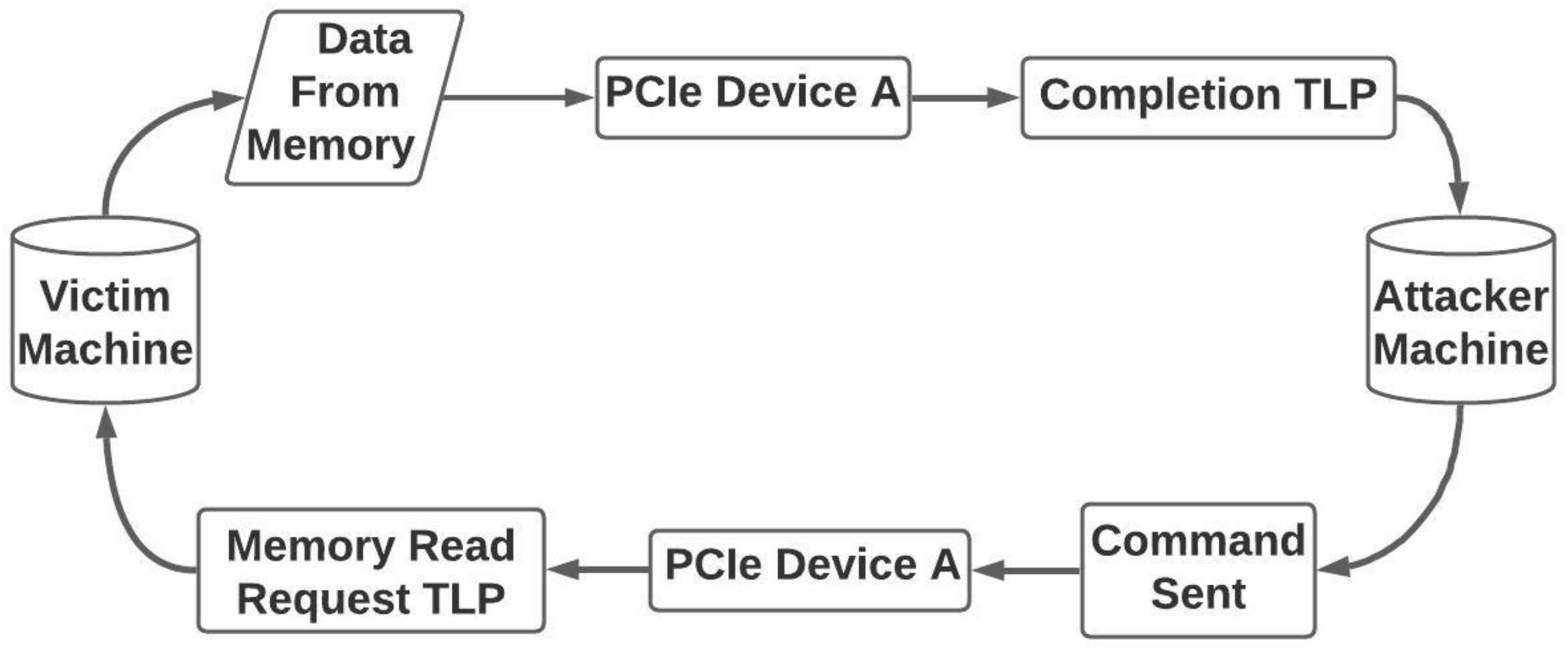
In this paper, we demonstrate a DMA attack using a compromised PCIe device to highlight the security risks of DMA. We created the attack using [18,25] attack models as references, and the basic flow of the attack is shown in Figure 3. In the victim machine, the PCIe device is connected to the PCIe port while being connected to the attacker machine by several interfaces such as either USB or Ethernet. Once the connection to the attacker machine is established, the attacker uses the PCIe device to send a Memory Read Request (MRd), a TLP, packet to the victim machine. When the MRd TLP arrives at the PCIe root complex, the victim machine fulfills the request and sends a completion TLP containing data from the host machine to the PCIe device, which sends the data to the attacker. This allows the attacker to access the main memory and dump the data using a specific range of addresses.
4. Proposed Methodology
The proposed authentication scheme integrates the access control of the PCIe devices and constructs a unique identifier for each PCIe device using profiling time. This unique identifier serves as a fingerprinting of each device. Due to the variation in the manufacturing process, each device has a unique physical characteristic such as current flow, IR drop, threshold voltage, and unique delays [26,27]. These delays affect the response time of the device. Manufacturing variations are also used in creating cryptographic functions such as Physical Unclonable Functions (PUFs).
A set of profile time of each device is collected and stored in a secure database during the registration process. The profile time is computed when a new device is connected for data transfer. High variance among multiple samples makes the raw data unusable for the applications of identification and authentication. In this work, we design a data processing framework to reduce the noise in raw measurements for extracting accurate and stable profiling time and develop machine learning model to improve the response time.
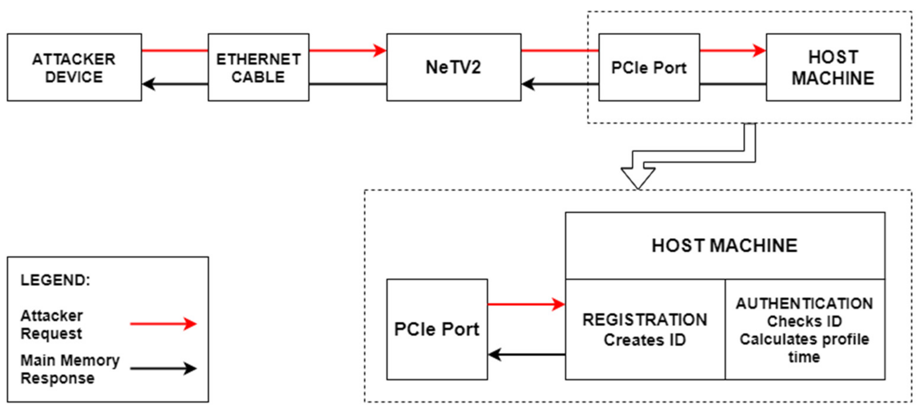
We propose a security extension for the PCIe device that can establish a secure connection to the main memory of the host machine. The proposed scheme adds two phase authentication processes to enable a secure access control of PCIe device and the host machine, shown in Figure 4. The first step is the registration process that runs once a new device is connected to the host machine. The device, once registered with the host machine, is considered trusted and is granted the access for the direct memory access. In registration step, a unique identifier is created for the PCIe device and added to a database of trusted identifies stored on the host machine. The second step is during the runtime when the PCIe device is connected back to the host machine or initiates a data transfer request, to establish authentication to allow the access and establish a secure connection. Once the registered device establishes the PCIe connection, the authentication process reads the vendor and device identifiers and checks them with the database of known trusted devices and compares the computed profiling time with the securely stored parameters of the registered devices.
We propose two schemes of identifier construction: the first one constructs the Region of Interest (ROI) and Range of Profiling Times (RPT), and the second scheme is a machine learning–based identifier construction. The paper evaluates the performance and accuracy of each technique and compares the two schemes in terms of time required for the registration of new devices and the time taken to authenticate a device at runtime.
4.1. Scheme 1: ROI- and RPT-Based Device Authentication Process
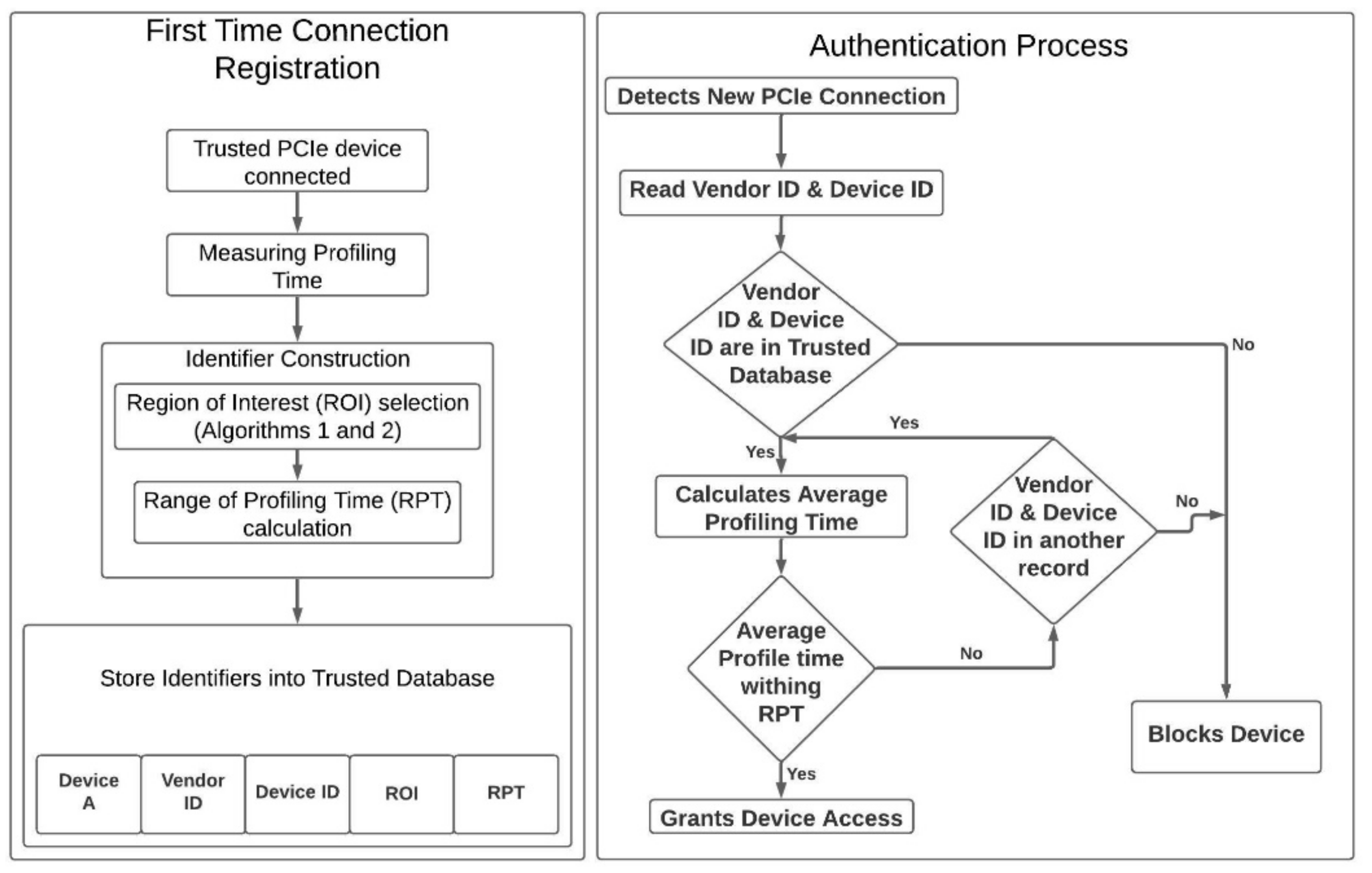
Figure 5 shows the workflow of the registration process and the authentication process of the proposed scheme. In registration process, the system creates a unique identifier for each device based on the profiling time and stores all the identifiers into its trusted database for authentication phase. In the authentication process, every time a device is inserted, the system verifies this device with the trusted database, and decides whether to grant permission or block the device based on the result of verification.
4.1.1. Trusted Device Registration
In order to begin the registration process, the host machine is connected to a trusted PCIe device during the enrollment phase. The database of trusted devices records a multitude of identifiers associated with the PCIe device such as Vendor ID, Device ID, Region of Interest (ROI), and Range of Profiling Time (RPT). For ROI and RPT to be calculated, an authorized system measures the profiling time of the connected device.
Data Collection
The profiling time for each device is measured in multiple sub-datasets, where each subset contains an equal number of measurements for profiling time. Each device is measured a total of (R × S) times, where R is the total number of sub-datasets for each device and S is the number of recorded profiling times in each sub-dataset. Once all data is collected from the measurements, the profiling times are ordered from lowest to highest within each sub-dataset.
Region of Interest (ROI) Selection
The ROI is used to find the region in the sub-dataset with the lowest noise. In the raw measurements of the data collected from the device, the variance is high, so the proposed scheme [20] calculates the most reliable ROI in the sub-dataset. One of the algorithms is a difference-based algorithm and the other is a correlation-based algorithm.
The Difference-based ROI (DROI) algorithm, denoted as Algorithm 1 [20], takes pairs of different sub-datasets and calculate the difference between them for the same region, starting with the first measurement and ending with the last one. In this algorithm, there are C (R, 2) possible combinations of different pairs for comparison with (S−L) possible regions, where L represents the length of the DROI.
| Algorithm 1 DROI selection. | ||||
| Inputs: Number of sub-data (R), Number of measurements in each sub-dataset (S), Length of DROI (L) | ||||
| Output: Difference-based ROI (DROI) | ||||
| Steps: | ||||
| 1: | Res[]← empty list | |||
| 2: | for i = 1 to (S – L) //for all the possible regions | |||
| 3: | for j = 1 to (R – 1) | |||
| 4: | for k = (j + 1) to R //for all the combinations | |||
| 5: | calculate AD (absolute difference value between sub-dataset[j][i : i + L] and sub-dataset[k][i : i + L]) | |||
| 6: | TD (accumulative difference for region i) ← TD+ AD | |||
| 7: | end for | |||
| 8: | end for | |||
| 9: | Res[i] ← TD | |||
| 10: | TD ← 0 | |||
| 11: | end for | |||
| 12: | DROI ← [d : d + L] where d is the index of the minimum value in Res[] | |||
With the Correlation-based ROI (CROI) algorithm, denoted as Algorithm 2 [20], a correlation coefficient, a statistical index for the dependency of variables, is computed for pairs of sub-datasets. Specifically, the Pearson’s correlation coefficient of all the regions in the pairs is computed.
| Algorithm 2 CROI selection | ||||
| Inputs: Number of sub-data (R), Number of measurements in each sub-dataset (S), Length of CROI (L) | ||||
| Output: Difference-based ROI (CROI) | ||||
| Steps: | ||||
| 1: | Res[]← empty list | |||
| 2: | for i = 1 to (S – L) //for all the possible regions | |||
| 3: | for j = 1 to (R – 1) | |||
| 4: | for k = (j + 1) to R //for all the combinations | |||
| 5: | calculate CC (correlation coefficient between sub-dataset[j][i : i + L] and sub-dataset[k][i : i + L]) | |||
| 6: | TC (accumulative coefficient for region i) ← TC+ CC | |||
| 7: | end for | |||
| 8: | end for | |||
| 9: | Res[i] ← TC | |||
| 10: | TC ← 0 | |||
| 11: | end for | |||
| 12: | CROI ← [d : d + L] where d is the index of the minimum value in Res[] | |||
For Algorithm 1, the Res is a list of all the difference of points of the sub-dataset pairs with a length of L ([i: i + L], starts from the ith point). From this Res, only the lowest values from each sub-dataset are used because the lower the difference mean is, the higher the similarity to other sub-datasets, meaning less noise. For Algorithm 2, the opposite is true, with the highest value in its Res list used because it is the highest correlation coefficient, which means high similarity. DROI and CROI are then represented on a graph of all the sub-datasets, and where the two overlap is considered to be the ROI, which will be used to construct the identifier.
Construct and Store Identifier
The process to calculate the ROI is to use it as the region where there is, statistically, the least amount of noise and use it as one of the unique identifiers for the trusted device database. The ROI is also used to find another identifier, the Range of Profiling Time (RPT). RPT is calculated by combing the average of all the measurements in the found ROI in each of the sub-datasets. The RPT and ROI are both used as identifiers along with vendor ID and device ID.
4.1.2. Authentication
The authentication process is initiated even before the device is accessed as the vendor ID and the device ID are both found by the system automatically when the device is connected to the host machine. If the two identifiers are found in the trusted device database, then the system measures the profiling time of the device multiple times and checks the ROI associated with that device. If the measurements are within the RPT the device is granted access. If the profiling time does not match the RPT then the system will check other records in the database with the same vendor and device IDs. If no matches are found, then the device is flagged and considered as the device has been tampered.
4.2. Scheme 2: Machine Learning–Based Authentication Process
The machine learning–based authentication scheme is evaluated by studying different techniques to predict the correct classification for the device ID given the measured profile times. The study includes Convolutional Neural Network, Multilayer perceptron network, and a Decision Tree algorithms–based classifiers [12,28,29,30,31]. The former two types of networks are part of a broad terminology called Deep Learning while the Classifier algorithm is part of Machine learning methods. Multilayer perceptron networks are a class of feedforward artificial neural networks. The model can have at least three layers with one input layer, one hidden layer and one output layer. Except for the input node, each node is a neuron that utilizes a non-linear activation function and utilizes a supervised learning technique called backpropagation for training. The non-linear activation functions in the neurons can distinguish between data that is not linearly separable. Two historically common activation functions used in these networks are described by:
The degree of error in an output node in the network for any particular data point can be given by:
where e is the error between the target value t and y which is the value produced by the network. With this, the node weights in the perceptron can be adjusted based on minimizing the error in the entire output by:
The change in each weight is given by gradient descent as:
where yi is the output of the previous neuron and η is the learning rate, which is selected to ensure the weights converge quickly without any oscillations. Similarly, Convolutional Neural Networks are regularized versions of Multilayer perceptron networks. CNNs in their approach towards regularization take advantage of the hierarchical pattern in data and assemble patterns of increasing complexity using smaller and simpler patterns embossed in filters. As the name suggests, these networks employ a convolution function rather than a traditional matrix multiplication function to compute the results, which is given by:
A convolutional neural network consists of hidden layers that perform the convolutions. This layer includes the multiplication or dot product and commonly, its activation function is Rectified Linear Unit (ReLU) [12]. This is followed by other convolution layers like fully connected layers, pooling layers, and normalization layers. While convolutional neural networks and multilayer perceptron networks follow the same working principle as mentioned above, they are a part of a subset of artificial intelligence called deep learning. The other two algorithms from machine learning subset, namely, the Decision Tree Classifier and the Random Forest Classifier, are investigated for authentication classifiers.
Decision trees classify samples by sorting them in the tree from the root to the leaf node with the leaf node providing the classification of the sample. Each node in the tree acts as a test case for some attribute and each edge descending from the node corresponds to possible answers in the test case. This process is recursive and is repeated for every subtree rooted at the new node. There are various algorithms which are used to split the decision trees, in this case the Decision Tree Classifier implements the CART (Categorical and Regression Tree) algorithm for the splits. The creation of sub-nodes increases the homogeneity of resultant sub-nodes, that is, the purity of the node increases with respect to the target variable. The decision tree splits the nodes on all available variables and then selects the split which results in most homogeneous sub-nodes. On the other hand, Random Forest Classifier is a supervised learning algorithm where the forest built is an ensemble of decision trees. The general idea of such ensemble is that a combination of learning models increases the overall result. The Random forest bodes well to perform when there are multiple features available as it takes the best feature among a random subset of features, unlike a decision tree which chooses the most important feature. We use Random forest as an experiment to gauge its performance in comparison to the decision tree and the other models when only one feature is present.
5. Experimental Setup and Results
The following section demonstrates the attack and implementation of the proposed countermeasures to mitigate the DMA attack.
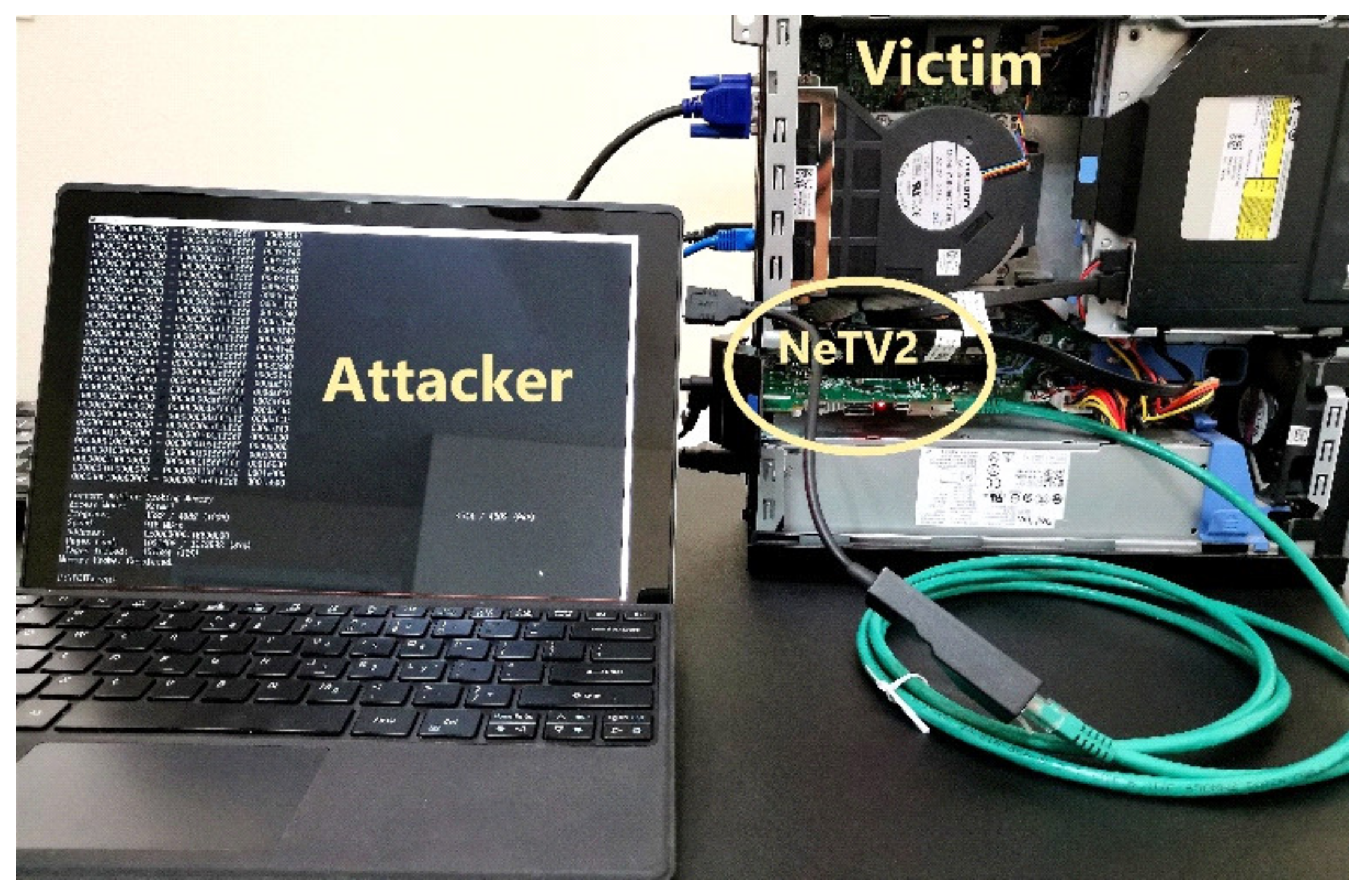
The experimental setup of the DMA attack includes the attacking device, NeTV2 board, connected to the victim machine via PCIe port. We used a PCIe-compatible development board named “NeTV2” with an onboard Xilinx XC7A35T FPGA chip. Xilinx provides PCIe DMA and PCIe Bridge hard and soft IP blocks for the compatible FPGA devices [32], as well as full access to 64-bit memory space without relying on a kernel module running on the victim system. The NeTV2 is physically connected with the ethernet cable to the attacker machine as shown in the Figure 6. The attacker does not require any software or hardware drivers on the victim machine; thus, the victim device cannot tell it is under attack. The direct access supported by DMA enables the attacker to control the NeTV2 board to send memory read/write request packets to the victim machine, and thereby to read/write data from/to the main memory on the victim machine.
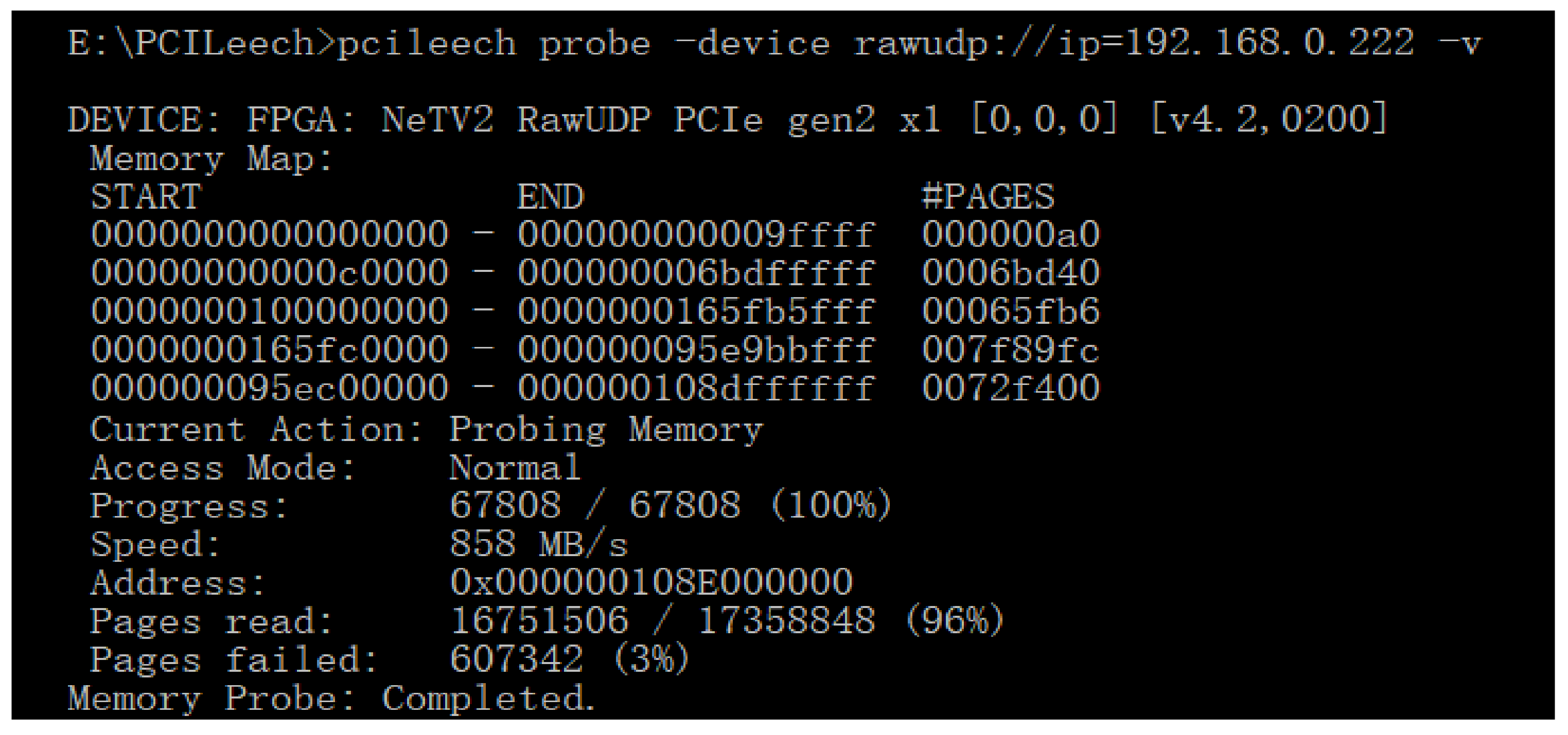
Figure 7 shows the process of memory probing. Under this attack the enumerated memory of the target system for readable memory pages starting from the first address to the last one. As shown in Figure 7, around 96% of the whole memory space is readable.
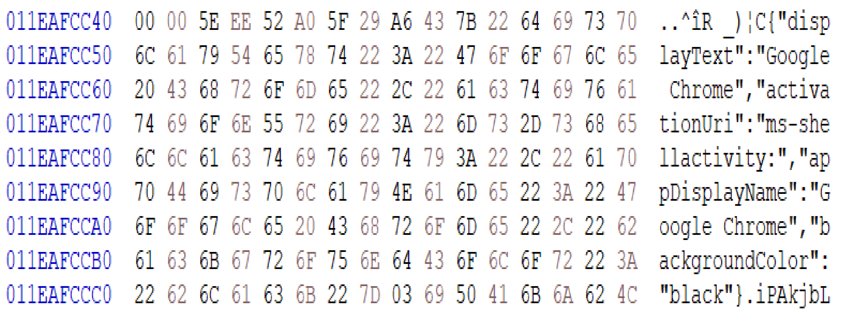
To further demonstrate the attack, Figure 8 shows a part of live memory dumped from the victim machine. This memory fragment is used by the Google Chrome browser during the attack of dumping the main memory illegally. The data can be extracted and stolen using the DMA attack. This shows that if security measures are not established the DMA can compromise the security and privacy of the victim device.
The following section describes the two authentication schemes discribed in the earlier sections proposed to mitigate the DMA attack. Section 5.1 describes the ROI and DROI–based authentication process and Section 5.2 discusses the machine learning algorithm–based device authentication.
5.1. ROI and DROI–Based Authentication
A number of TL-WN881ND wireless PCIe adapters from TP-LINK [33] are used to compute the profile time, that is, the elapsed time of reading configuration space on the PCIe device. The devices have the same architecture and vendor properties; however, the profile time is unique to each device because of the manufacturing process variations. Each device measures the elapsed time to read the configuration space on the PCIe device and this delay is used as a metric of profiling time. The profiling time is used as unique identifier for the trusted PCIe device.
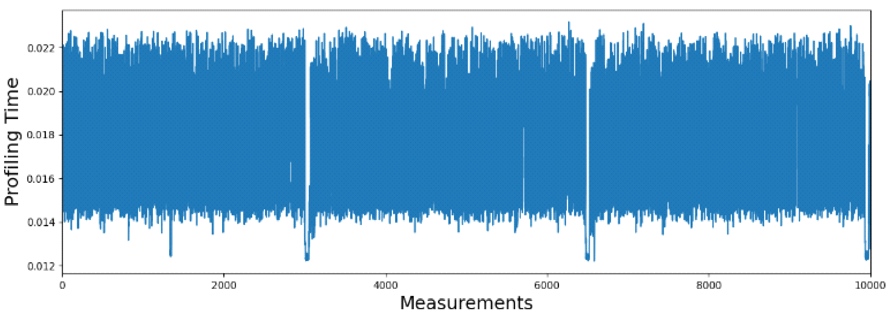
The profiling time is collected using several samples and an average profile time is computed to remove the measurement noise. Figure 9 shows 10,000 sample measurements of profiling time for one of the devices, referred to as device A. The profiling time shows the consistent range over different samples with a variance of 13 ms to 23 ms. The range is small and overall stays consistent over time during the collection of 10,000 samples. The ranges can cause aliasing if the similar behavior is shown across different devices. So ideally we need a sub-range for a unique set of delays are used for the device identification.
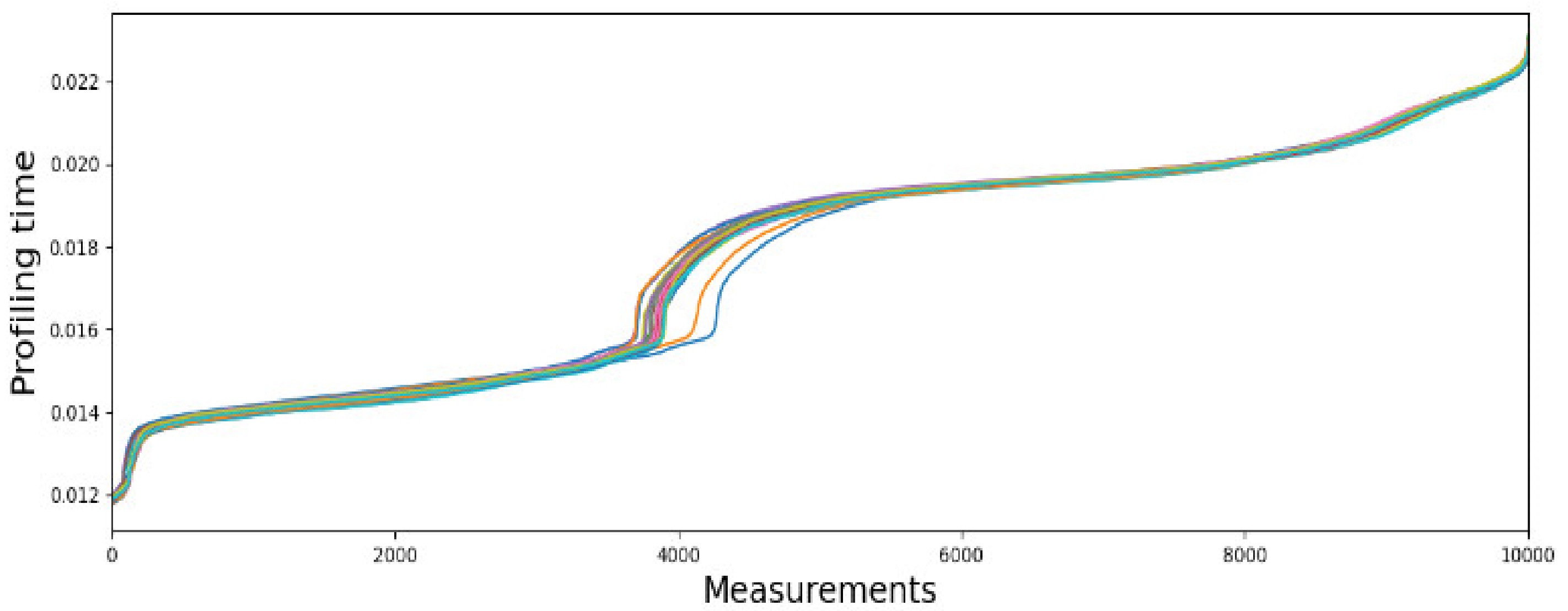
Furthermore, the profile time can be affected with the environment variations. The measurements are organized into 30 sub-datasets, with each 30 subsets of data collected over time to integrate the environmental variations across temperature and other environment variations of each device (Device A is shown in Figure 10). Figure 10 shows 30 sub-datasets with sorted measurements collected from device A. Without data processing, the variance of profiling time is very high (from 12 ms to 23 ms), and the difference among different sub-datasets is also very high in some regions, which makes identifier construction vulnerable to aliasing and bit flips in the device identifier construction.
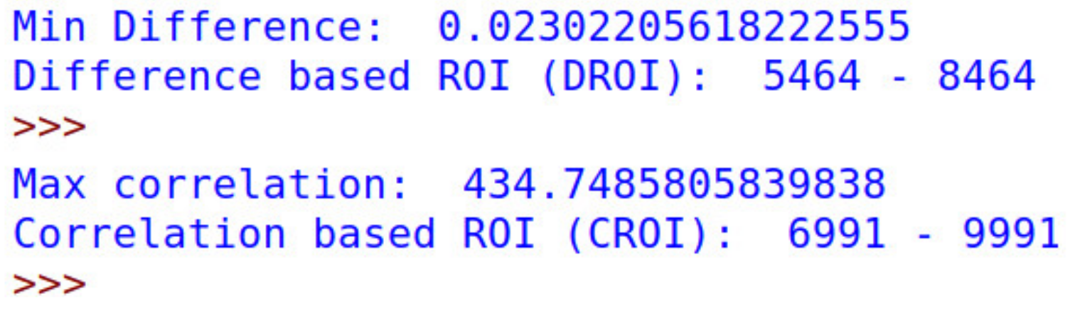
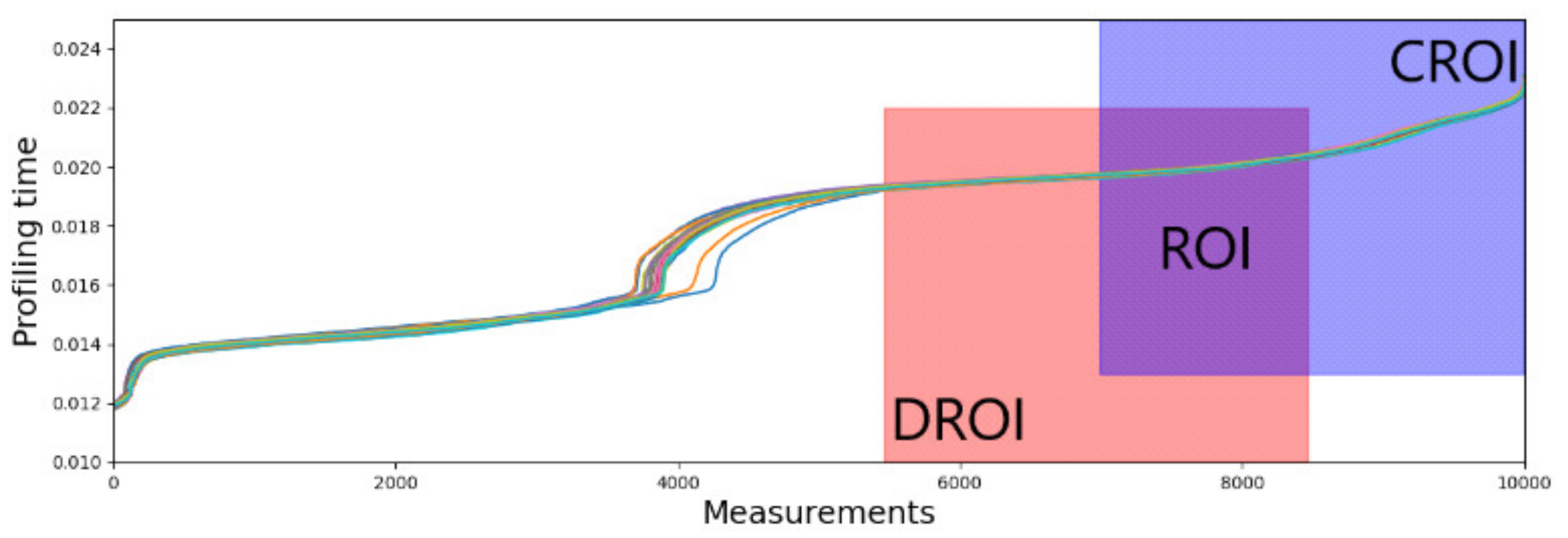
In the test configurations, the length parameter of DROI and CROI is set to 3000. Figure 11; Figure 12 show the result of DROI selection and CROI selection. The range of subsets from the measurements taken from device A are then input into the two algorithms DROI and CROI. In Figure 11, the results of the proposed algorithms show the profiling time for the DROI algorithm, with the range of measurements over time ranging from 5464–8464, as shown in the Figure 12. Similarly, the result of ideal profiling time using CROI is from the 6991st point to the 9991st point. The results represent the chosen DROI and the CROI, respectively, being limited to a length of 3000 for the purposes of our experiments to have a sizable ROI. While the length of CROI and DROI is flexible, if the ROI is too wide it can cause the RPTs to overlap, and if the ROI is too narrow, the success rate of the authentication is reduced.
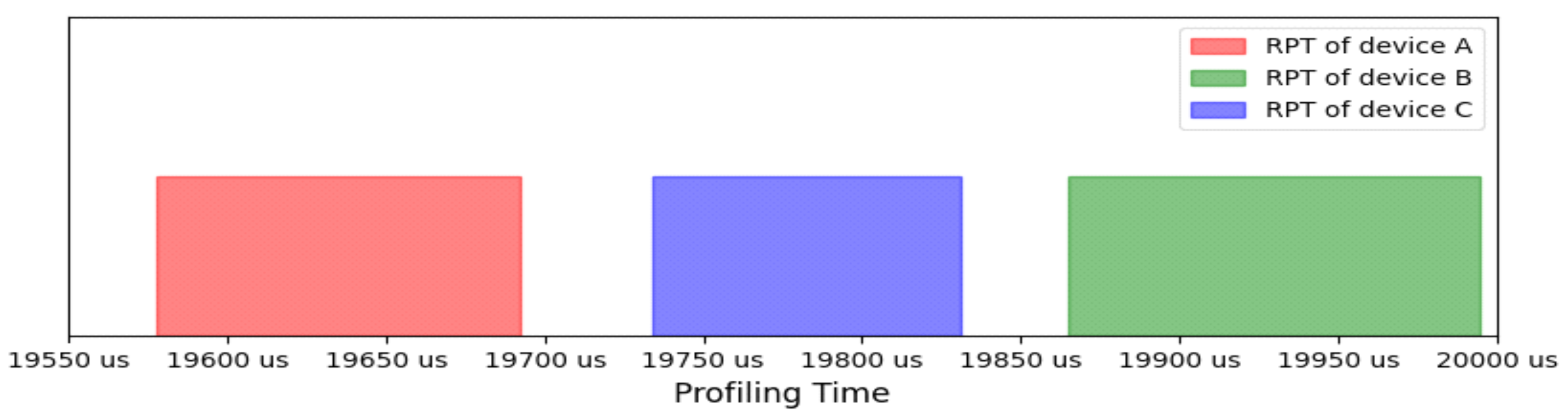
The results of the profile time selection are shown in Figure 12. The highlighted section of DROI and CROI and the overlap region of the two subregions is used as ROI, ranging from 6991st point to the 8464th point for the device A. This region has the lowest noise and the highest stability because samples in this region from data collections over different periods (sub-datasets in this case) have both the lowest difference and the highest correlation with each other. Moreover, based on the result of comparison among these devices, all the devices of the same type have very similar ROIs with each other, so we used the ROI of device A for all the devices used in the experiment to construct the identifier. Figure 13 shows the unique range of profile time using the ROI and shows that each device is uniquely identified using the proposed algorithm.
The average profiling times of all the sub-datasets is used as the RPT for each device. As shown in Figure 13, RPTs range from 19,577.90 us to 19,692.26 us; 19,865.05 us to 19,994.50 us; and 19,734.17 us to 19,831.31 us for device A, B, and C, respectively. There is no overlapped area among the three devices, which means that the RPT of each device is unique. RPTs were used as identifiers of each device and stored in the trusted database with vendor ID, device ID, and ROI on the host machine for future authentication.
The ROI-based scheme is compute extensive and takes longer time to authenticate, that is, takes up to several minutes and thus can slowdown the performance. To improve the response time, we propose an ML-based authentication scheme that uses the raw measurements processes it without computing the CROI and DROI.
5.2. Machine Learning–Based Authentication
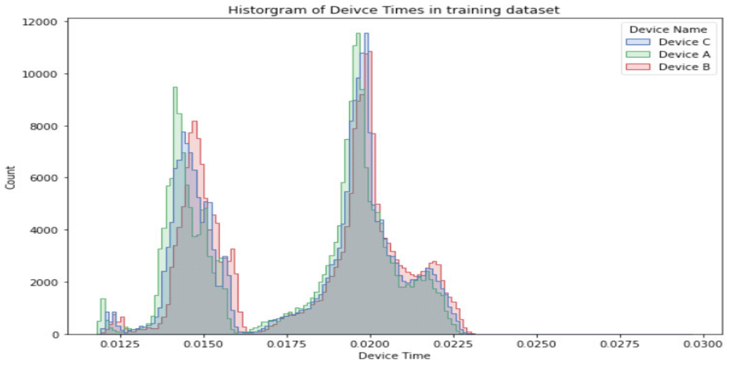
The Machine Learning ML models of convolutional neural networks and decision trees are used to classify the devices into unique class for the device identification. A dataset of 900,000 records of device profiling times were collected, divided into training and test sets to uniquely identify device ID. In the convolutional neural networks, the data is processed to encode the categorical variables, that is, device names, using an ordinal encoder and assign an integer value to them [11]. The dataset is split into training and testing sets randomly, comprising of 720,000 and 180,000 records, respectively. The distribution of training data comprised of three device IDs, each approximately equal in number, shown in in Figure 14. The machine learning algorithms use the raw data of profile times, which saves any preprocessing delays for classification; however, a large overlap between the device profile times is seen as multiple devices can have the same value. This methodology is independent of the first technique discussed in Section 5.1, with advantage of no preprocessing required during the authentication or classification process, as that was required to determine CROI and DROI. On the contrary, the ML-based scheme uses raw data as it is.
The Convolutional Neural Network is comprised of five convolutional layers where each layer has 64 neurons. A dropout layer is added after the first two convolutional layers to introduce regularization in the network. Convolution operations results are flattened and connected to a dense layer to predict the final authentication predictions. The network is trained for 30 epochs using a batch size of 1000 samples to speed up training process. The network required 333.42 s for training on a 2.2GHz 2vCPU machine. The best fit of the model is used to make predictions on the test dataset. The results show 33.32% accuracy in the predictions made by the network. The hyperparameters chosen for this model depended on hardware experiments starting from two CNN layers going up to seven layers, including changing the number of epochs (iterations) and the batch size of the model. The batch size as a parameter is a portion of the data that the model can see during one iteration. Thus, if we increase the batch size, the time taken to train the model will be reduced but at the cost of accuracy, as information in the data can be lost. Hence, choosing the right balance of hyperparameters is important as high number of layers can lead to the problem of overfitting and again decrease the accuracy. Table 1 gives a summary of the results of these experiments.
Increasing the convolutional layers after five not only increased the time to train but also reduced the accuracy signalling overfitting. Thus, we selected the parameters highlighted in green as that was the best fit of the model.
The other model of ML using Multilayer perceptron is configured with a two-hidden-layer network and 100 neurons in each layer. This network is trained for 50 epochs using a batch size of 1000 samples. This model took 152.45 s for the training process on the same machine. With a best fit model, the results show an accuracy of 40.3% in the predictions made by the network on test dataset.
The third ML model, that is, the Decision Tree Classifier, yields an accuracy of 39.2% which is comparable to the Multilayer perceptron network but took only a marginal 5.025 s to run using the same machine configuration. The algorithm developed 41,292 leaves and a depth of 64, implying that the longest path from root to a leaf node comprised of 64 intermediate steps [11].
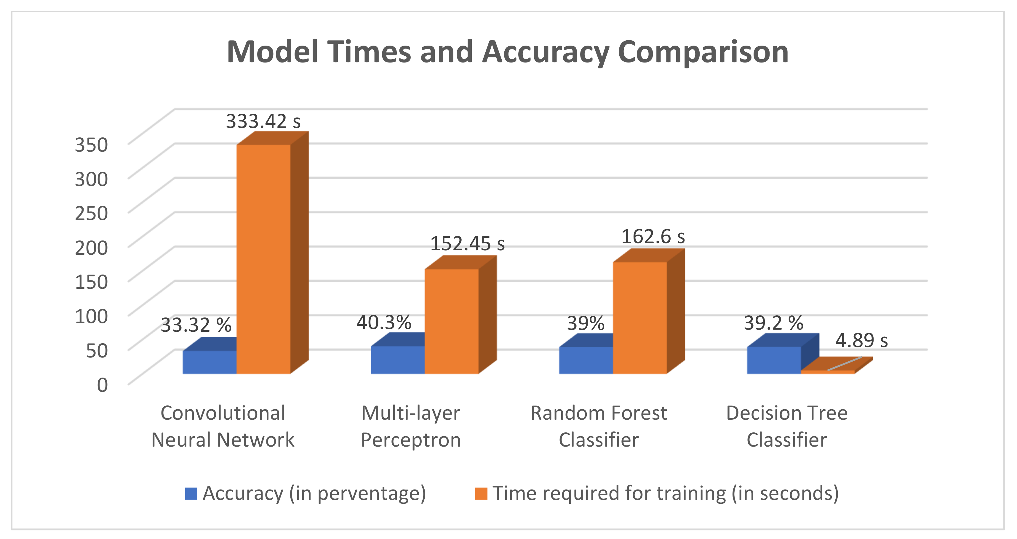
The Decision Tree Classifier and Random Forest Classifier have the same working principles but differ in methodology. While the two schemes have comparable accuracy to the other models, the time taken by the Random Forest Classifier was significantly more than the Decision Tree, as can be seen in Figure 15.
In Figure 15, the bar graph shows the training time for four machine learning models, namely, Convolutional Neural Network, Multilayer Perceptron, Random Forest Classifier, and the Decision Tree Classifier. The Decision Tree Classifier shows a significant improvement in the time required for training in comparison to the Multilayer perceptron network, which has the highest accuracy in this comparison but takes the order of minutes for execution. Multilayer perceptron and Convolutional networks fail in datasets like these because there is only one feature variable that is directly affecting the target output, which is profile time.
The datasets are used as raw values without preprocessing the profile time for the machine learning model to improve the delay in the identifier computation. However, these delays have overlap between the device time values corresponding to their device IDs, that is, several devices can have similar profile time values in the raw data. This can result in wrong classification by the convolutional neural network, hence affecting the accuracy of the results/identification of the devices. The CNN performs worse than the other models tested here because, since it is a deep layered network, it tries to model the differences or variations in the input data. In this case, as we know there is a big overlap in the input data for the classification, the model has a hard time modeling those and specifically taking only one feature into account. If more features are provided, the network can perform with more accuracy as the addition of more features helps to give a more deterministic idea to the network for classification.
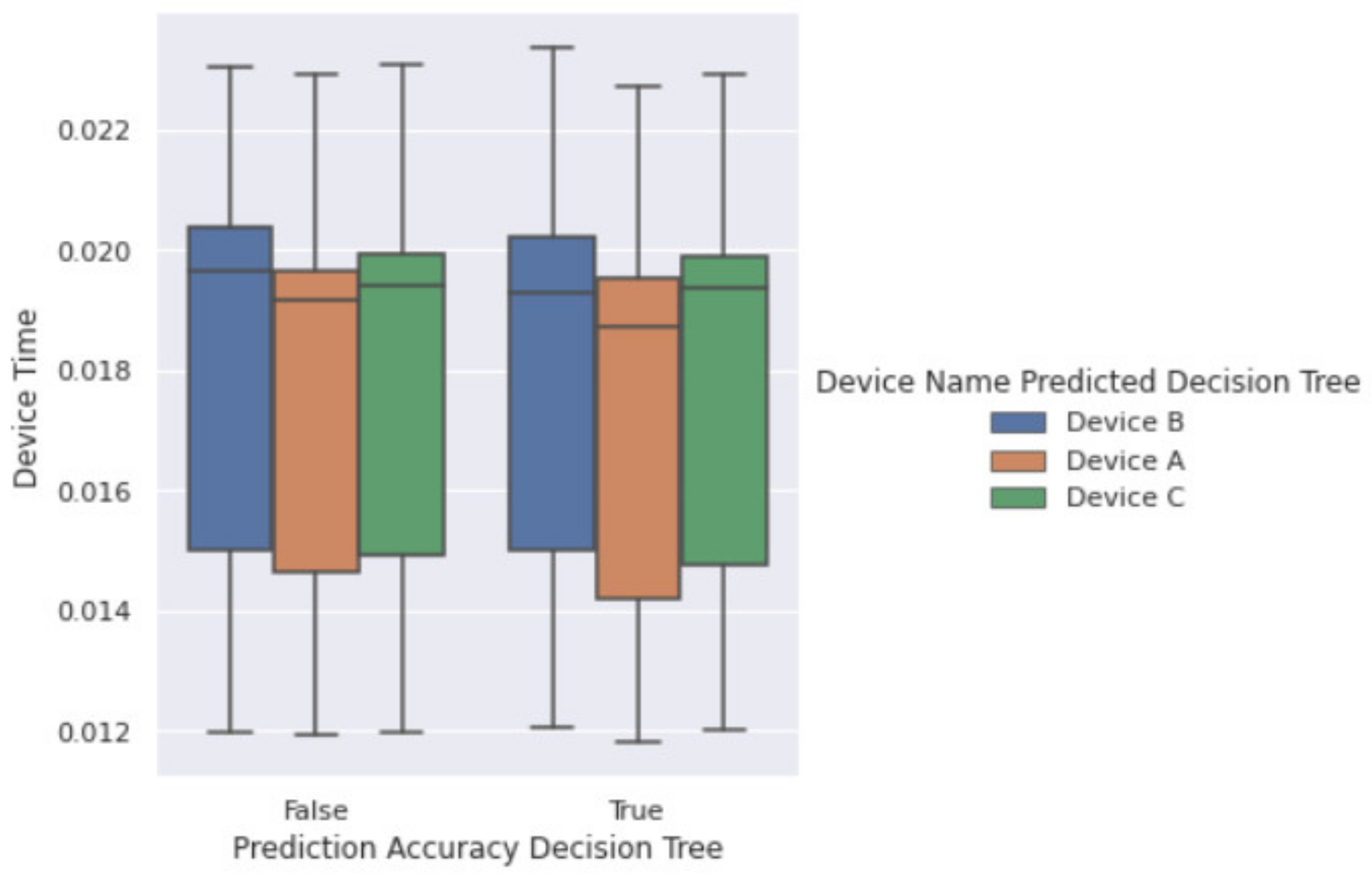
Figure 16 shows a box plot of predictions made by Decision Tree Classifier. The X-axis has the categories of the comparison column, indicating whether a prediction is true or false depending on the comparison between the actual ID and the predicted ID from the model. We can see from this plot that the median values for all three devices lies between 0.019 s to 0.020 s, making it difficult for the classifier to distinguish between the three devices. This effect is the major reason for the low accuracy overall. However, the advantage of using such algorithms is using raw data directly without additional overhead of preprocessing. The results show that the Decision Tree Classifier is the best performing model by giving comparable accuracy to some of the deeper models and at the same time utilizing a marginal amount of time to train (4.89 s) in comparison to the model with the best accuracy (Multilayer perceptron taking 152.45 s). That is approximately 96% reduction in training time for a marginal 1.1% reduction in the accuracy, which is very significant considering the resource utilization for training these models.
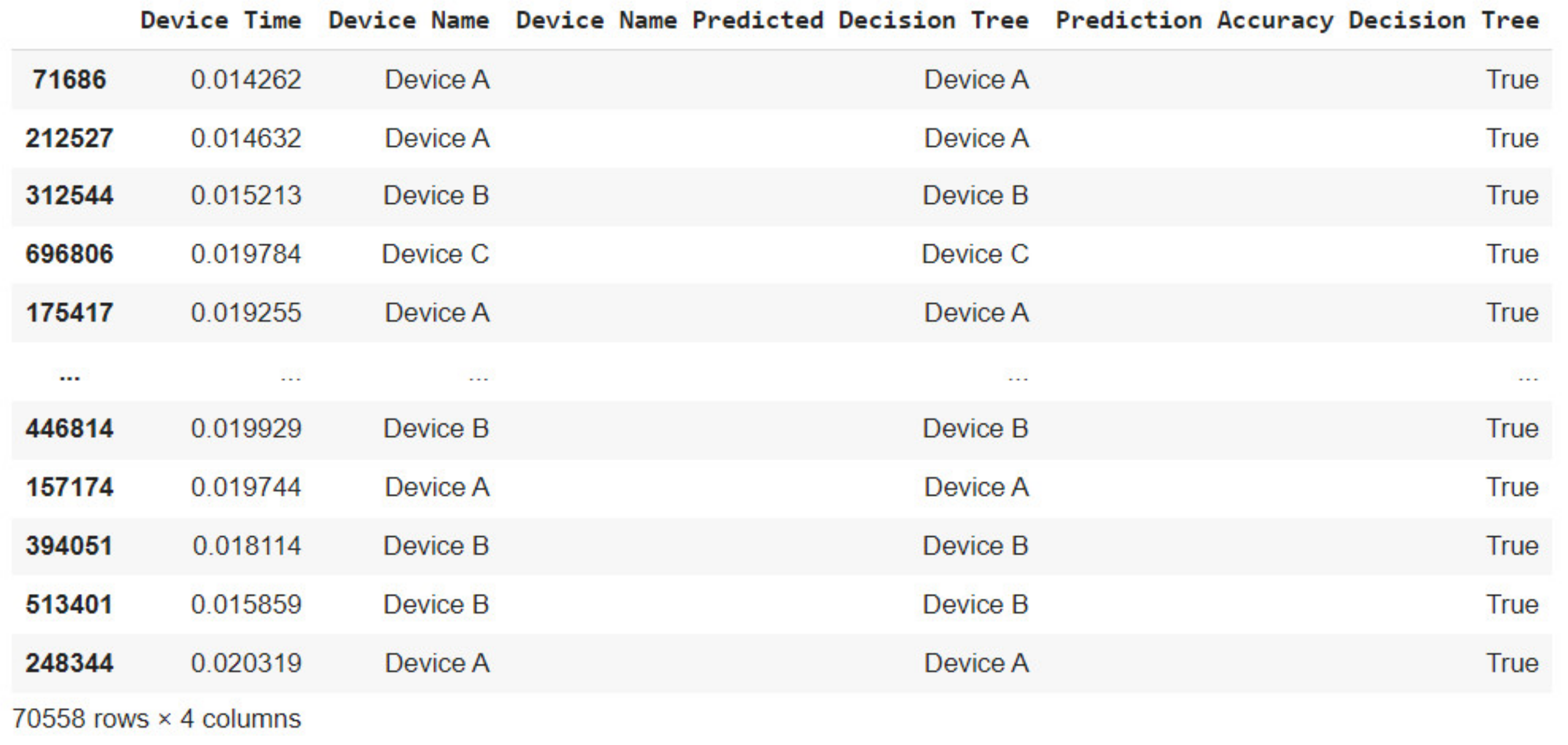
From Figure 17, we can see the correct predictions made by the Decision Tree Classifier. The comparison column (Prediction Accuracy Decision Tree) indicates the same with the value “True”. From a total of 180,000 test dataset, the Decision Tree Classifier correctly predicted 70,558 device IDs based on the raw device profile times.
6. Security Analysis
The proposed methodology uses profiling time to construct unique identifiers to detect if a trusted PCIe device is connected to the host machine. Compared to the existing countermeasures, the proposed method has two advantages:
- The advantage of the delay-based authentication is that no hardware or protocol modifications are needed. Existing countermeasures such as [34,35] require changes to the internal protocol of the host machine or the actual physical components that the system uses. Heavy modifications are harder to implement in a real-world setting, whereas our method only needs to measure characteristics of the hardware, and not change it.
- Secondly, the proposed scheme causes little strain on performance and resource overhead. While one efficient countermeasure to DMA attacks is IOMMU, it has been shown that using IOMMU causes a significant drop in performance [36]. The proposed authentication schemes, on the other hand, require the devices to register once they are connected to the host machine, and when the authentication process is successful, there is no additional overhead in packet transmission during the data transfers over DMA. This thus keeps the average performance for large data transfer not largely affected.
Analyzing the overall effectiveness of the design, the resource overhead and time overhead are shown in the Table 2. Resource overhead refers to storage space of the trusted database; considering that an average system will not have an excess amount of PCIe devices, the trusted database for the system will be relatively small. With a table of 30 devices, it would only require 1.81 KB of storage.
Time overhead includes the time it takes to complete authentication for a device once it is connected and can successfully initiate the data transfers. The time overhead is separated into two categories, that is the registration overhead and the authentication overhead. The measurements for both time overheads are shown in Table 2. It is shown that the measuring of a new device takes 100 min to complete; to have an accurate RPT, we collected over 300,000 measurements for each device. The construction time for creating an identifier for the first time is 15.7 min due to the amount of data collection and preprocessing. While the registration overhead is large, it is only a one-time occurrence and needs to be done only once when a new trusted device is connected to the host machine. As for authentication overhead, the measuring process only took 3.4 min, and the construction of the identifier takes 4 × 10⁻⁷ min. The authentication process only needs fewer, that is, 10,000 measurements. It should be noted that the time overhead, specifically the construction time will vary depending on the CPU of the host machine. Throughout this experiment, a Core i5-3470 was used for both registration and authentication.
For this experiment, a Python-based interface for PCIe was used and the python time library was used to collect the profiling time of the devices. One issue remains, which is the extremely high variance of the profiling time, as demonstrated in Figure 9. While Algorithm 1 and Algorithm 2 were created to find the ROI with the lowest noise, the variance causes two major issues:
- The first issue is RPT overlapping. Though there was no overlapping with RPT in the experiment, as shown in Figure 13, if the number of recorded devices increase dramatically, it could cause some devices to have their RPT overlap and make the identifier no longer unique to that device. One way to mitigate that would be to have the devices be of different models and from different manufactures.
- The other issue is registration time overhead. This problem occurs because more measurements are recorded to have higher accuracy with the high variance in the profile times. If we are somehow able to reduce the variance of the profiling time, then less samples would be needed for the registration, thus lowering the time over head significantly. However, more accurate measurements were not feasible during the experiment.
Machine learning algorithms are applied for classification. The prediction times from all four algorithms explored takes a few seconds on average. This is possible since the model has been trained on a training set. With more data, the model can be trained using more resources and time, where resulting in the reduced or same authentication time would still give near real-time results, that is, one or two seconds with the existing training set, as compared to a minutes-long process. The model training happens offline, and to infer a set of samples during test phase, the model takes near real-time (~1 to 2 s on average) for a set of 180,000 samples in 2 s for classification of all the devices. The delay associated with the data collection is the same for the ML-based scheme that is 10,000 samples per 3.4 min, however, the measurement delay can be reduced for the ML-based authentication by using fewer data samples for classification.
The machine learning models use raw data with a significant overlap between the profile times for the devices but accurately authenticate the devices with 40% accuracy. The identifier construction overhead for machine learning algorithms has a limited accuracy; however, the machine learning has an advantage when raw data is used as it best performs with the overhead of identifier construction in 4.89 s and authenticate the device within few seconds (1 to 2 s on average). This near real-time performance is made possible by the advancements in machine learning, and as the dataset grows, algorithms keep getting better and we can expect promising results from such machine learning algorithms.
7. Conclusions
The paper demonstrates the DMA attacks and propose ROI- and Machine learning–based secure authentication process for the DMA devices. The paper explores several machine learning models and demonstrate the accuracy and performance improvements for machine learning–based authentication. The proposed security measures create authentications scheme for PCIe devices that use DMA with their unique profiling time. Furthermore, the ROI selection algorithms reduces the measurement noise in the profiling information. The authentication process has a success rate of 100% with no overlapping area among the three PCIe devices’ RPTs. This is a lightweight scheme that does not require physical modifications to the system hardware or protocols and does not impact the overall performance of the system. The machine learning algorithms are further explored to improve the time efficiency and accuracy. The computed profile time can change over time, such as the change of environmental parameters and real-time resource utilization, causing bitflips because of aging and environmental variations, which will be further studied to improve the accuracy of authentication process over time.
Author Contributions
Conceptualization, Y.G. and F.S.; methodology, Y.G., C.B. and M.H.; writing—original draft preparation, M.H., C.B. and Y.G.; writing—review and editing, F.S.; supervision, F.S.; project administration, F.S.; funding acquisition, F.S. All authors have read and agreed to the published version of the manuscript.
Funding
This research was funded by NSF, grant numbers 1814420, 1819694 and 1819687.
Data Availability Statement
The data presented in this study are available in article.
Conflicts of Interest
The authors declare no conflict of interest.
References
- Suh, G.E.; Clarke, D.; Gassend, B.; van Dijk, M.; Devadas, S. AEGIS: Architecture for tamper-evident and tamper-resistant processing. In Proceedings of the ACM International Conference on Supercomputing 25th Anniversary Volume, Munich, Germany, 10–13 June 2014; pp. 357–368. [Google Scholar]
- McKeen, F.; Alexandrovich, I.; Berenzon, A.; Rozas, C.V.; Shafi, H.; Shanbhogue, V.; Savagaonkar, U.R. Innovative instructions and software model for isolated execution. Hasp@ Isca 2013, 10. [Google Scholar] [CrossRef] [Green Version]
- Xu, Y.; Cui, W.; Peinado, M. Controlled-Channel Attacks: Deterministic Side Channels for Untrusted Operating Systems. In Proceedings of the 2015 IEEE Symposium on Security and Privacy, San Jose, CA, USA, 17–21 May 2015. [Google Scholar]
- Bit Locker Countermeasures (Windows 10)—Microsoft 365 Security. Available online: https://docs.microsoft.com/en-us/windows/security/information-protection/bitlocker/bitlocker-countermeasures#pre-boot-authentication (accessed on 17 September 2020).
- Intel® Virtualization Technology for Directed I/O (VT-d). Available online: https://software.intel.com/content/www/us/en/develop/articles/intel-virtualization-technology-for-directed-io-vt-d-enhancing-intel-platforms-for-efficient-virtualization-of-io-devices.html (accessed on 17 September 2020).
- Han, Q.; Wu, L.; Zhang, X. Research on Side Channel Attack for USB Key. In Proceedings of the 2016 12th International Conference on Computational Intelligence and Security (CIS), Wuxi, China, 16–19 December 2016. [Google Scholar]
- ZZShim, K.A. A Survey of Public-Key Cryptographic Primitives in Wireless Sensor Networks. IEEE Commun. Surv. Tutor. 2016, 18, 577–601. [Google Scholar]
- Morgan, B.; Alata, E.; Nicomette, V.; Kaâniche, M. Bypassing IOMMU Protection against I/O Attacks. In Proceedings of the 2016 Seventh Latin-American Symposium on Dependable Computing, Cali, Colombia, 19–21 October 2016. [Google Scholar]
- When Lightning Strikes Thrice: Breaking Thunderbolt 3 Security. Available online: https://thunderspy.io/ (accessed on 20 September 2020).
- Dixit, P.; Silakari, S. Deep Learning Algorithms for Cybersecurity Applications: A Technological and Status Review. Comput. Sci. Rev. 2021, 39, 100317. [Google Scholar] [CrossRef]
- Pedregosa, F.; Varoquaux, G.; Gramfort, A.; Michel, V.; Thirion, B.; Grisel, O.; Blondel, M.; Prettenhofer, P.; Weiss, R.; Dubourg, V.; et al. Scikit-learn: Machine learning in Python. J. Mach. Learn. Res. 2011, 12, 2825–2830. [Google Scholar]
- Chollet, F. Deep Learning with Python, 1st ed.; Manning: New York, NY, USA, 2018; pp. 1–117. [Google Scholar]
- 8237A High Performance Programmable DMA Controller. Available online: https://www.lo-tech.co.uk/downloads/manuals/intel/Intel-8237A-datasheet.pdf (accessed on 28 February 2021).
- Memory Mapping and DMA. Available online: https://www.oreilly.com/library/view/linux-device-drivers/0596005903/ch15.html (accessed on 28 February 2021).
- Savage, S.V.; Harris, J.M. Direct Memory Access Controller for Improved System Security, Memory to Memory Transfers, and Interrupt Processing. U.S. Patent 4,797,853, 10 January 1989. [Google Scholar]
- Tanwar, P.K.; Thakur, O.M.; Bhimani, K.; Purohit, G.; Kumar, V.; Singh, S.; Raju, K.S.; Ishii, I.; Raut, S. Zynq SoC Based High Speed Data Transfer Using PCIe: A Device Driver Based Approach. In Proceedings of the 2017 14th IEEE India Council International Conference, Roorkee, India, 15–17 December 2017. [Google Scholar]
- Böck, B.; Austria, S.B. Firewire-Based Physical Security Attacks on Windows 7, EFS and BitLocker. Secur. Bus. Austria Res. Lab 2009. [Google Scholar]
- Direct Memory Attack the Kernel. Available online: https://media.defcon.org/DEF%20CON%2024/DEF%20CON%2024%20presentations/DEF%20CON%2024%20-%20Ulf-Frisk-Direct-Memory-Attack-the-Kernel.pdf (accessed on 15 September 2020).
- John, T.M.; Haider, S.K.; Omar, H.; van Dijk, M. Connecting the dots: Privacy leakage via write-access patterns to the main memory. IEEE Trans. Dependable Secur. Comput. 2020, 17, 436–442. [Google Scholar] [CrossRef] [Green Version]
- Gui, Y.; Siddiqui, A.S.; Nicholas, G.S.; Saqib, F. A Lightweight Delay-based Authentication Scheme for DMA Attack Mitigation. In Proceedings of the 22nd International Symposium on Quality Electronic Design (ISQED), Santa Clara, CA, USA, 7–9 April 2021; pp. 263–268. [Google Scholar]
- Perez, R.; Sailer, R.; van Doorn, L. vTPM: Virtualizing the Trusted Platform Module. In Proceedings of the 15th Conference on USENIX Security Symposium, Vancouver, BC, Canada, 31 July–4 August 2006. [Google Scholar]
- AMD I/O Virtualization Technology (IOMMU) Specification. Available online: https://www.amd.com/en/support/tech-docs/amd-io-virtualization-technology-iommu-specification (accessed on 20 September 2020).
- Fletchery, C.W.; Ren, L.; Yu, X.; van Dijk, M.; Khan, O.; Devadas, S. Suppressing the Oblivious RAM timing channel while making information leakage and program efficiency trade-offs. In Proceedings of the 2014 IEEE 20th International Symposium on High Performance Computer Architecture (HPCA), Orlando, FL, USA, 15–19 February 2014. [Google Scholar]
- Wendlandt, D.; Andersen, D.G.; Perrig, A. Perspectives: Improving SSH-style Host Authentication with Multi-Path Probing. In Proceedings of the 2008 USENIX Annual Technical Conference, Boston, MA, USA, 22–27 June 2008. [Google Scholar]
- PCILeech. Available online: https://github.com/ufrisk/pcileech (accessed on 25 September 2020).
- Suh, G.E.; Devadas, S. Physical Unclonable Functions for Device Authentication and Secret Key Generation. In Proceedings of the 44th Annual Design Automation Conference, San Diego, CA, USA, 4–8 June 2007; Association for Computing Machinery: New York, NY, USA, 2007. [Google Scholar]
- Lee, J.W.; Lim, D.; Gassend, B.; Suh, G.E.; van Dijk, M.; Devadas, S. A technique to build a secret key in integrated circuits for identification and authentication application. In Proceedings of the 2004 Symposium on VLSI Circuits, Honolulu, HI, USA, 17–19 June 2004. [Google Scholar]
- Saqib, F.; Dutta, A.; Plusquellic, J.; Ortiz, P.; Pattichis, M.S. Pipelined decision tree classification accelerator implementation in FPGA (DT-CAIF). IEEE Trans. Comput. 2013, 64, 280–285. [Google Scholar] [CrossRef]
- Che, W.; Martinez-Ramon, M.; Saqib, F.; Plusquellic, J. Delay model and machine learning exploration of a hardware-embedded delay PUF. In Proceedings of the IEEE International Symposium on Hardware Oriented Security and Trust, Washington, DC, USA, 30 April–4 May 2018. [Google Scholar]
- Sarker, I.H. Cyber Learning: Effectiveness analysis of machine learning security modeling to detect cyber-anomalies and multi-attacks. Internet Things 2021, 14, 100393. [Google Scholar] [CrossRef]
- Geetha, R.; Thilagam, T. A Review on the Effectiveness of Machine Learning and Deep Learning Algorithms for Cyber Security. Arch. Comput. Methods Eng. 2021, 28, 2861–2879. [Google Scholar] [CrossRef]
- PCI Express and Xilinx Technology. Available online: https://www.xilinx.com/products/technology/pci-express.html (accessed on 26 September 2020).
- TL-WN881ND. Available online: https://www.tp-link.com/il/home-networking/adapter/tl-wn881nd/ (accessed on 29 September 2020).
- PCIe® Component Authentication. Available online: https://pcisig.com/pcie%C2%AE-component-authentication (accessed on 25 September 2020).
- PCIe * Device Security Enhancements Specification. Available online: https://www.intel.com/content/www/us/en/io/pci-express/pcie-device-security-enhancements-spec.html (accessed on 10 October 2020).
- Ben-Yehuda, M.; Xenidis, J.; Ostrowski, M.; Rister, K.; Bruemmer, A.; van Doorn, L. The Price of Safety: Evaluating IOMMU Performance. In Proceedings of the 2007 Ottawa Linux Symposium, Ottawa, ON, Canada, 27–30 June 2007. [Google Scholar]
Figure 1.
Two types of data transfer with DMA.

Figure 2.
Configuration space.

Figure 3.
Basic DMA Attack flow.

Figure 4.
Block Diagram of the Proposed Scheme.

Figure 5.
Proposed registration and authentication scheme.

Figure 6.
Experimental setup of DMA attack.

Figure 7.
Memory probing on victim machine.

Figure 8.
A memory fragment dumped from the victim machine.

Figure 9.
A total of 10,000 measurements of profiling time in one sub-dataset collected from device A.
Figure 9.
A total of 10,000 measurements of profiling time in one sub-dataset collected from device A.

Figure 10.
Comparison of all 30 sorted sub-datasets collected from device A.

Figure 11.
The output of DROI selection and CROI selection.

Figure 12.
Result of DROI selection and CROI selection.

Figure 13.
Range of Profiling Time (RPT) of each device.

Figure 14.
Histogram of profiling times corresponding to their respective device names in the training set.
Figure 14.
Histogram of profiling times corresponding to their respective device names in the training set.

Figure 15.
Time required for training and accuracy for each of the four models.

Figure 16.
Box Plot showing False and True predictions made by Decision Tree Classifier.

Figure 17.
Correct predictions made by the Decision Tree Classifier.


Table 1.
CNN Experimentation Results Summary.
| CNN Layers | Number of Epochs | Batch Size | Time Required to Train (Seconds) | Accuracy (%) |
|---|---|---|---|---|
| 2 | 70 | 1000 | 154.82 | 19.46 |
| 4 | 70 | 1000 | 258.12 | 28.15 |
| 4 | 100 | 1000 | 302.78 | 30.08 |
| 5 | 100 | 1000 | 548.64 | 30.15 |
| 5 | 50 | 1000 | 500.12 | 32.15 |
| 5 | 50 | 5000 | 351.82 | 32.81 |
| 5 | 30 | 1000 | 333.42 | 33.32 |
| 6 | 30 | 1000 | 372.14 | 33.12 |
| 7 | 30 | 1000 | 400.12 | 32.94 |
Table 2.
Time Overhead (Single Device).
| Time Overhead | Registration Overhead (Minutes) | Authentication Overhead (Minutes) | Authentication Overhead (Machine Learning) (Seconds) | |||
|---|---|---|---|---|---|---|
| Measuring | Construction | Measuring | Construction | Training | Prediction | |
| 100 min | 15.7 min | 3.4 min | 4 × 10⁻⁷ min | 4.89 s | ~1 s | |
Publisher’s Note: MDPI stays neutral with regard to jurisdictional claims in published maps and institutional affiliations. |
© 2021 by the authors. Licensee MDPI, Basel, Switzerland. This article is an open access article distributed under the terms and conditions of the Creative Commons Attribution (CC BY) license (https://creativecommons.org/licenses/by/4.0/).
Share and Cite
MDPI and ACS Style
Gui, Y.; Bhure, C.; Hughes, M.; Saqib, F. A Delay-Based Machine Learning Model for DMA Attack Mitigation. Cryptography 2021, 5, 18. https://0-doi-org.brum.beds.ac.uk/10.3390/cryptography5030018
AMA Style
Gui Y, Bhure C, Hughes M, Saqib F. A Delay-Based Machine Learning Model for DMA Attack Mitigation. Cryptography. 2021; 5(3):18. https://0-doi-org.brum.beds.ac.uk/10.3390/cryptography5030018
Chicago/Turabian StyleGui, Yutian, Chaitanya Bhure, Marcus Hughes, and Fareena Saqib. 2021. "A Delay-Based Machine Learning Model for DMA Attack Mitigation" Cryptography 5, no. 3: 18. https://0-doi-org.brum.beds.ac.uk/10.3390/cryptography5030018