Asymmetric Hysteresis Loops in Co Thin Films


1
Faculty of Engineering and Mathematics, Bielefeld University of Applied Sciences, Interaction 1, 33619 Bielefeld, Germany
2
Institute of Physics—Center for Science and Education, Silesian University of Technology, ul. Konarskiego 22B, 44-100 Gliwice, Poland
*
Author to whom correspondence should be addressed.
Condens. Matter 2020, 5(4), 71; https://0-doi-org.brum.beds.ac.uk/10.3390/condmat5040071
Submission received: 23 October 2020
/
Revised: 30 October 2020
/
Accepted: 4 November 2020
/
Published: 5 November 2020
(This article belongs to the Section Magnetism)
Abstract
:Asymmetric magnetic hysteresis loops are usually found in exchange bias (EB) systems, typically after field cooling a system below the Néel temperature of an antiferromagnet exchange coupled to a ferromagnet. Alternatively, asymmetric hysteresis loops may occur due to undetected minor loops or in systems with a rotational anisotropy. Here, we report on an exchange bias thin film system MgO(100)/Co/CoO, examined at room temperature, which is far above the blocking temperature, by the magneto-optical Kerr effect (MOKE). While the longitudinal hysteresis loops partly show steps which are well-known from diverse purely ferromagnetic systems, the transverse hysteresis loops exhibit clear asymmetries, similar to exchange biased systems at low temperatures, and unusual transverse magnetization values at saturation. Since minor loops and a rotational anisotropy can be excluded in this case, this asymmetry can possibly be a residue of the exchange bias coupling at lower temperatures.
1. Introduction
Magnetic hysteresis loops of ferromagnetic (FM) materials are usually symmetric, independent from the ferromagnet’s shape. Asymmetric hysteresis loops, on the other hand, are in some technologically controlled situations attributed to exchange bias (EB) systems. Such an exchange bias is a unidirectional anisotropy, occurring in exchange-coupled systems of ferromagnet and antiferromagnet (AFM) after field cooling (cooling in the presence of an externally applied magnetic field) the system from high temperatures significantly below the Néel temperature of the AFM [1,2,3]. Quite pronounced asymmetries are known, e.g., from thin layer systems such as Fe/MnF2 [4], while several other systems also show asymmetries which are often especially well visible in the transverse magnetization component (i.e., perpendicular to the external magnetic field orientation) [5,6,7,8]. Other systems, such as Co/CoO, often show symmetric hysteresis loops even at low temperatures [9].
In addition to such exchange bias systems, there are other possibilities how asymmetric magnetic hysteresis loops can be created. A typical one, sometimes applied on purpose, sometimes based on improper measurements, is related to minor loops. Such minor loops can be used, e.g., to measure first order reversal curves (FORC), which allow for calculating reversible and irreversible loop components and contain additional information about the investigated system [10,11,12]. On the other hand, it is possible to measure minor loops erroneously, since a hysteresis loop seems to be closed, but parts of the sample are not fully reversed, or a hard axis in a thin film sample is not yet crossed [3,13,14,15]. Harres et al. gave some criteria to avoid such undesired minor loops: Singularities in the magnetization should be observed by successive derivations of the magnetization with respect to the external magnetic field; by finding the maximum positive field which is sufficient to acquire the remanent magnetization; and by measuring zero field cooling/field cooling curves, allowing for estimating the anisotropy field [14]. The first ideas are not highly reliable for measurements using the magneto-optic Kerr effect (MOKE)—the standard approach in laboratories—since here usually the noise is higher than in more advanced superconducting quantum interference device (SQUID) method and other techniques. In addition, the absolute vertical position of the loop is not defined, making subsequent remanence measurements prone to errors due to thermal drift. The last criterion is not available in measurements at room temperature. In MOKE measurements, instead, a good possibility is based on measuring longitudinal (parallel to the external magnetic field) and transverse magnetization components (perpendicular to the field) at the same time or generally measuring with more than one polarization, in this way making the small features well visible which can be missed [4,15].
A more scarcely investigated possibility is a chiral magnetic order due to the Dzyaloshinskii-Moriya interaction in inversion-asymmetric crystals [16], which is not relevant for inversion-symmetric bulk metals and thus, not taken into account here.
In a recent study, we investigated MgO(100)/Co/CoO thin film systems far above the blocking temperature of the exchange bias in these samples and found not only deviations from the expected crystallographic fourfold symmetry, but also we have seen clearly asymmetric transverse magnetization components that can be compared—which is one of the main aims of this paper—with a few other literature reports on similar effects in systems without an exchange bias. MgO substrates are well suited for growing Co due to a small lattice mismatch which allows growing epitaxial Co layers in (111), (110), and (100) orientations on the respective MgO substrates [9]. In addition, especially the system MgO(100)/Co/CoO was investigated earlier at low temperatures and showed an unexpected rotational anisotropy below the blocking temperature. Thus, it is interesting to investigate whether other unusual effects may occur in this system at room temperature, i.e., well above the blocking temperature.
2. Materials and Methods
Molecular-beam epitaxy (MBE) was used to prepare thin films in the stacking order MgO(100) substrate/Co (8 nm)/CoO (20 nm). While Co was grown at 300 °C with a growth rate of 2–3 Å/min, for the CoO layer, an oxygen atmosphere of 3.3 × 10⁻⁷ mbar was applied which is known to result in CoO layers with a low defect concentration [17]. Applying reflection high-energy electron diffraction (RHEED), the Co layer was shown to grow in (100) fcc orientation with the easy axes at (45 + n·90)°, while the subsequent CoO layer grew in a twinned (100) orientation with axes slightly tilted against the Co axes. In a previous study, this sample type revealed a strong asymmetry of longitudinal (ML) and transverse magnetization components (MT) below the blocking temperature of approx. 260 K [18].
Measurements were performed by MOKE in a longitudinal setup at room temperature, i.e., well above the blocking temperature. By using a diode bridge technique and setting the polarization of the incident laser beam to 45°, i.e., between s- and p-polarization, the transverse magnetization component can unambiguously be measured in the longitudinal setup [4].
Additional micromagnetic simulations were performed by the object oriented micro magnetic framework (OOMMF) [19]. Simulation parameters were Ms = 1400 × 103 A/m, A = 30 × 10−12 J/m, and K1 = 520 × 103 J/m3, as originally implemented in OOMMF and corresponding to common literature values [20]. Since Co usually grows hcp, we tested the common uniaxial anisotropy in addition to a fourfold anisotropy. For the latter, the other simulation parameters were kept unchanged since only a qualitative comparison with the experiments was planned. Anisotropy axes were set to 45° for the easy axis of the sample with uniaxial anisotropy and ±45° as easy axes of the fourfold sample, equivalent to the real sample.
The Gilbert damping constant was set to α = 0.5 to simulate a quasistatic case. A round nanodot of thickness 10 nm and radius 500 nm was modelled, in this way reducing the impact of the shape anisotropy. The mesh size of the elementary cubes was set to 5 nm.
The simulation revealed angular ranges in which peaks of different shapes were visible in the transverse magnetic components and allowed for measuring the difference between MT at a negative and at a positive saturation, here described as ΔMT,sat. This value is related to the torque working on the magnetization, which is proportional to sin(θH−θM) with the angle θH of the applied field and the angle θM of the magnetization [21] and can thus be used to understand the anisotropy of a sample qualitatively.
3. Results
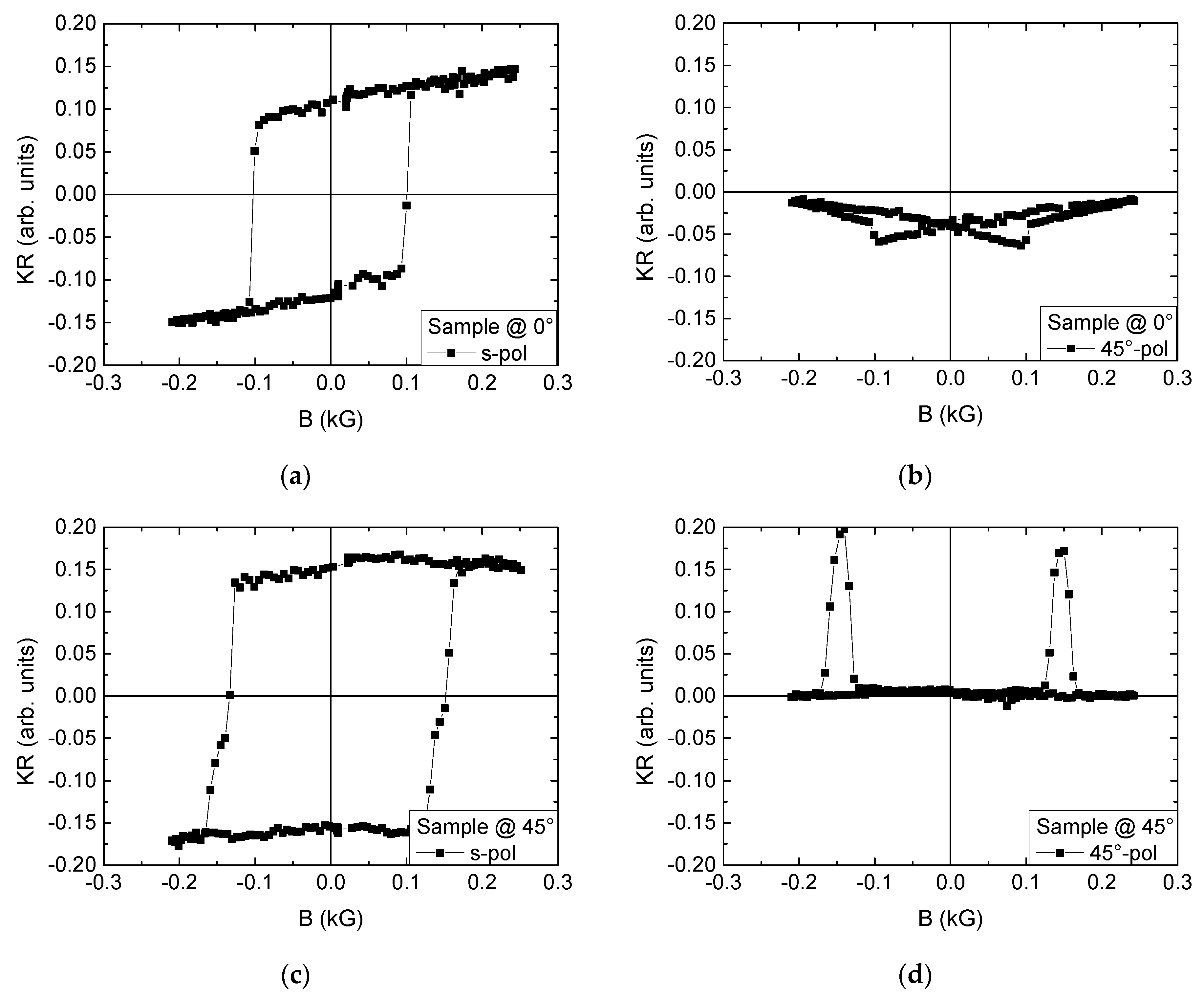
Figure 1 shows longitudinal and transverse magnetization components, measured in a longitudinal MOKE setup in s- and 45°-polarization, with sample orientations of 0 and 45°, respectively.
On the one hand, both longitudinal loops look similar, without the possibility to state definitely whether these are hard or easy axes. At 45°, steps in the slope of the hysteresis loop are visible which cannot be found at 0°. Comparing the transverse hysteresis loops on the other hand, a more distinct difference is visible. The peaks at 0 and 45° are oriented oppositely, and those measured at 45° show a clearly different shape than the 0° peaks, which is correlated to the steps in the longitudinal loop being only visible at a sample orientation of 45°.
Further measurements showed highly similar results at 90 and 135°, respectively, which fits to the aforementioned fourfold anisotropy in the fourfold Co layer. In addition, no horizontal shifts of the hysteresis loops are visible, in agreement with measuring well above the blocking temperature of this system. Nevertheless, the transverse magnetization components show a clear asymmetry, with both peaks having identical orientations, while a fully symmetric reversal necessitates peaks with contrary signs in both halves of the hysteresis loops. It must be mentioned that a rotational anisotropy could be excluded by approaching these angles after clockwise and counterclockwise rotation of the sample in a positive saturation field and measuring identical signals for both rotational orientations. Such a rotational anisotropy occurs in this type of sample at temperatures well below the blocking temperature [18]. Measuring at a temperature of 215 K, we found a horizontal loop shift depending on the rotation direction if the sample was field cooled from 300 K along a hard axis (0 or 180°), and a superposition of the fourfold horizontal loop shift due to the rotational anisotropy and a unidirectional horizontal loop shift due to the exchange bias for field cooling along an easy axis (45°). Similarly, the orientation of the transverse peaks changed according to the rotational direction [18]. Here, however, the transverse peak orientation cannot be attributed to such a rotational anisotropy.
To understand this behavior better, Figure 2 shows some chosen transverse magnetization components. While most angles show indeed an asymmetric transverse hysteresis loop, there are also some angles (e.g., 15, 105, 125°) where no such clear asymmetry is visible.
At an angle of 25°, only a slight asymmetry is visible, with the left peak being clearly broader than the right one. Going on to 35°, the right peak is vanished, while the left one has become narrower. Rotating the sample further to 55° results in the opposite situation with a peak only on the right side. For a sample orientation of 115° in a sample of fourfold anisotropy, the transverse magnetization could be expected to be similar to either (115 − 90° = 25°), which is clearly not the case, or to 65° (for a mirror symmetry at 90°), which is not the case, either (MT(65°) looks very similar to MT(55°)). This, in addition to the asymmetries found in most transverse hysteresis loops, clearly shows that here a simple fourfold anisotropy is not sufficient to describe the magnetic properties of this sample type reliably.
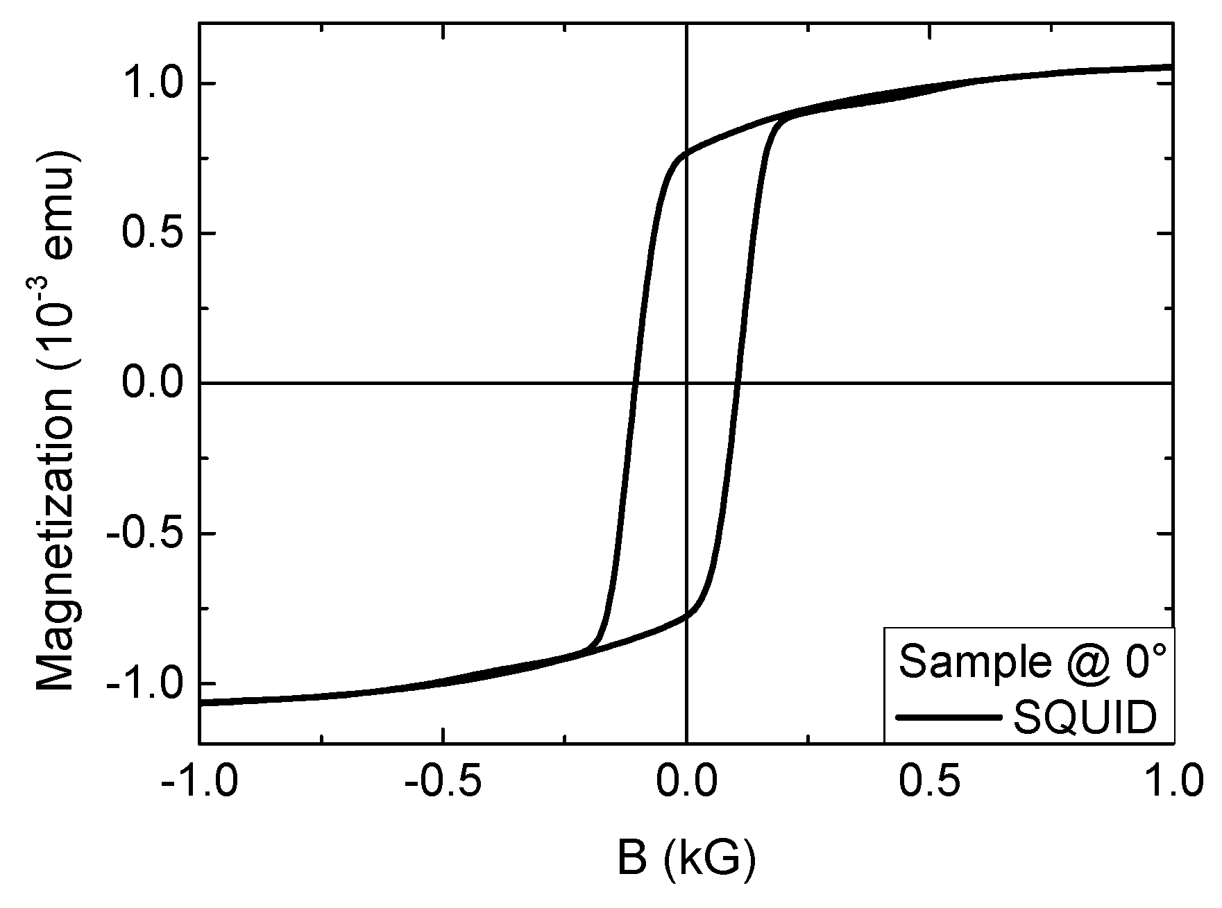
To test whether this effect may be based on minor loops, a SQUID was used to measure a longitudinal hysteresis loop in fields up to 10 kG, which showed no sign of a broad step which might have been undetected in the MOKE measurements (Figure 3). Afterwards, identical MOKE signals were measured as shown here. In addition, as mentioned before, areas with unreversed magnetization usually become visible when varying the polarization of the incident laser beam, in this way probing also magnetization orientations between longitudinal and transverse directions. Tests with varying the polarization in steps of 5° did not reveal any hint on a minor loop at sample orientations of 0 and 45°, respectively.
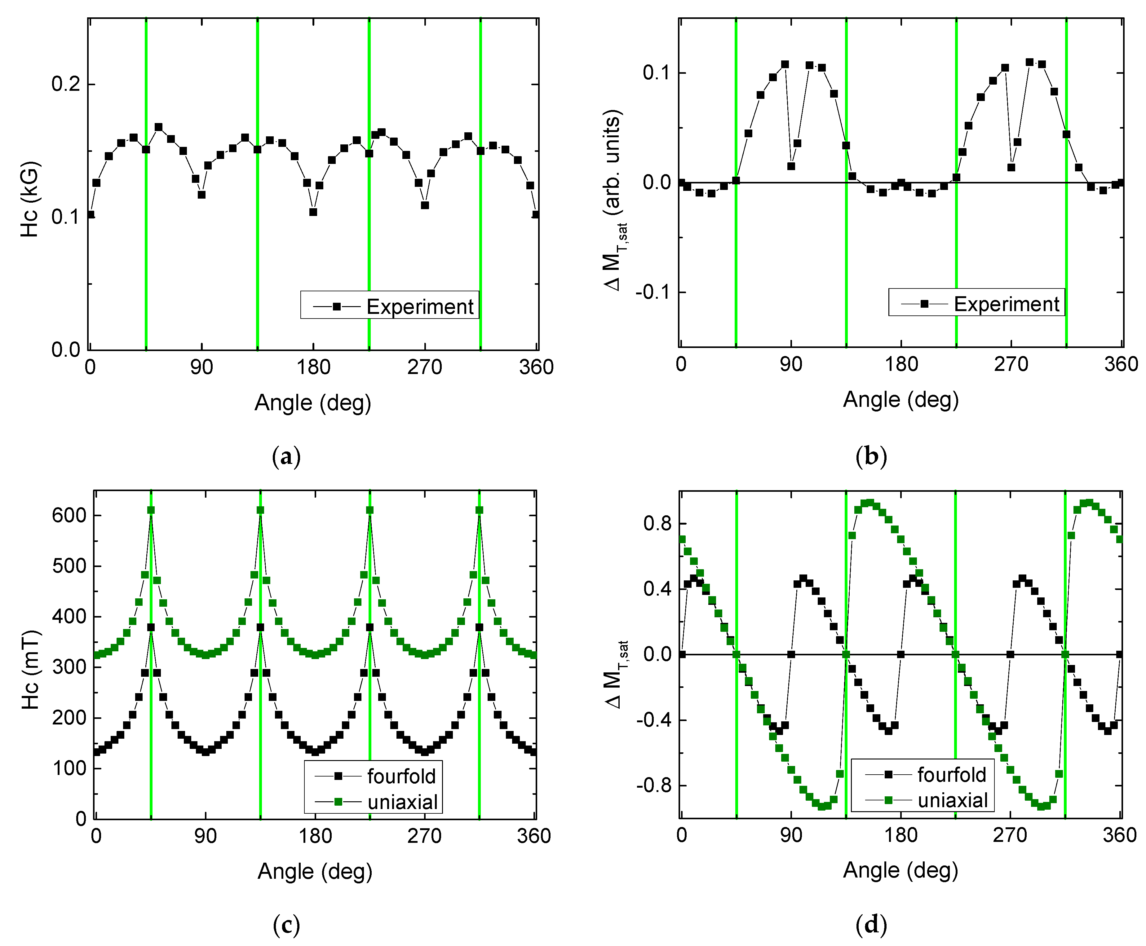
For the whole set of measurements, the coercive fields as well as the aforementioned differences between transverse magnetization values at a negative and positive saturation ΔMT,sat are depicted in Figure 4. The coercive fields show indeed a fourfold symmetry, which should be compatible with the expected fourfold anisotropy. The value ΔMT,sat, however, behaves completely differently. Here, only a twofold asymmetry is visible. Generally, the shape of this curve is hard to describe.
This is why Figure 4c,d depicts the same parameters, as derived from the simulation, using a fourfold and a uniaxial model. Starting with the coercive fields, the fourfold symmetry can be found for both simulations, independent from the chosen anisotropy. The shape, however, looks quite different from the one of the experimental curve. It should be mentioned that the shape found here is typical for a system which can be modelled according to the Stoner-Wohlfarth model, while systems with noncoherent magnetization reversal which can be described by the wall-motion model of Kondorsky show a similar slope, but with abrupt jumps near the hard axes [22].
One possible explanation is based on a potential error in MOKE measurements. Since even small deviations from s- or p-polarization are sufficient to add a part of the transverse magnetization component, square transverse peaks (cf., e.g., Figure 2a,d) can shift steps along the slopes of the hysteresis loops so that erroneously either a wrong coercive field or an apparent exchange bias may be measured [4]. Indeed, Figure 1c shows such steps in the longitudinal loop for a sample orientation of 45°. Evaluating the complete polarization-dependent measurement cycle from s- to p-polarization, however, does not show larger coercive fields for any magnetization component.
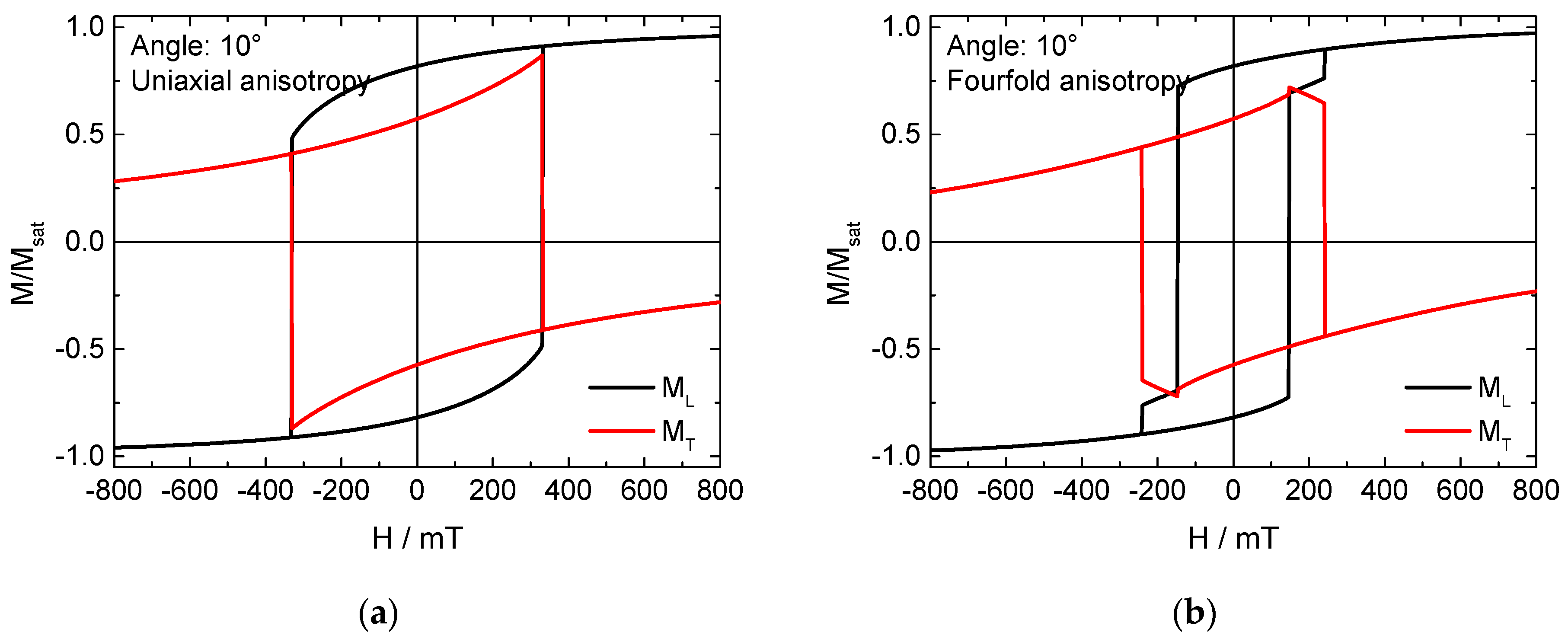
In the simulation, on the other hand, this problem cannot occur. Figure 5 depicts longitudinal and transverse hysteresis loops, simulated for a sample angle of 10°, assuming a uniaxial or a fourfold anisotropy, respectively. The uniaxial anisotropy (Figure 5a) leads for all angles to typical Stoner-Wohlfarth hysteresis loops without any steps or peaks. The fourfold anisotropy sometimes energetically favors magnetization reversal via the easy axis oriented 90° to a positive and negative saturation, resulting in the typical step in the longitudinal loop and the corresponding peaks in the transverse loop (Figure 5b). This, however, happens here only in the angular range of 5…15° and not near 45°, where simulations and experimental results differ the strongest; meaning that near 45° the simulation cannot show two coercive fields which may become visible for different magnetization orientations.
Next, the parameter ΔMT,sat should be discussed. In the simulation, the fourfold and the uniaxial anisotropy lead to clearly distinct slopes of ΔMT,sat vs. the sample angle, with two (four) maxima and four (eight) zero-crossings for the uniaxial (fourfold) anisotropy. Generally, the easy axes can be recognized as the angles where the curves approach the x-axis slowly before they change sign, while the hard axes also show a zero-crossing, but with a much steeper slope.
Transferring this to the experimental results (Figure 4b), however, is complicated. “Slow” sign changes can indeed be found at (45 + n·90)°, i.e., along the easy axes. Much steeper slopes are visible around 90 and 270°, which are indeed hard axes. Here, however, the parameter ΔMT,sat does not reverse its sign, nor does this happen at 0 and 180°, although the hysteresis loops measured at the four hard axes are nearly identical.
These findings will be discussed in detail in the next section.
4. Discussion
There are two experimental findings which need an explanation: The asymmetry of the transverse magnetization components, and the completely unclear slope of ΔMT,sat.
Starting with the asymmetry, this property of magnetic systems is usually found in exchange bias systems, as mentioned before. In addition to the most typical EB system, composed of a ferromagnet exchange-coupled to an antiferromagnet, there are also less usual material combinations or even pure materials that are able to exhibit an exchange bias, such as the recently found NiMn2O4 [23,24]. Similarly, in several material systems, it cannot be excluded that ferromagnetic clusters form in antiferromagnetic metal oxides, or that the surface of a ferromagnetic metal is unintentionally oxidized to an antiferromagnetic state [25,26]. These effects, however, cannot explain the asymmetry found here—the system Co/CoO is well-known as an exchange bias system, however, not at temperatures above the blocking temperature. Thinking about over-oxidizing the AFM layer to Co3O4 is not supportive, either, since this AFM has an even smaller Néel temperature of only 40 K.
Sometimes asymmetric loops are claimed to be visible, which are quite small and, depending on the measurement method, may be attributed to polar contributions or similar effects [27]. In addition to exchange biased samples, clear asymmetric hysteresis loops usually occur only as minor loops [28]. One exception, however, must be mentioned here: While normally magnetic nanostructures do not exhibit a loop shift or asymmetric hysteresis loops, as long as they are not erroneously probed by minor loops, simulations of defects in permalloy strips with uniaxial anisotropy revealed indeed asymmetric loops due to domain wall pinning at these defects [29]. This, again, does not have to be taken into account here.
After excluding the impossible options, there is only one left, besides the further explanations not detected. As mentioned before, the blocking temperature of CoO(100) in the type of sample investigated here was regularly found to be approximately 260 K, i.e., more than 30 K below room temperature (21–22 °C). The Néel temperature of CoO, however, is indeed similar to room temperature, i.e., between approx. 280 and 310 K, based on different studies [30]. It must be mentioned that in Co(110)/CoO systems, a strong effect due to the 90° coupling between AFM and FM can be observed around 280–320 K [9], indicating that the AFM cannot be ignored above room temperature, even if the measurement temperature is well above the blocking temperature. Such an effect was reported by Roy et al. for Ni/NiO nanoparticle systems, however, showing also a horizontal shift of the hysteresis loop, which is not visible here [31]. Nevertheless, especially with respect to the well-known impact of the AFM in Co(110)/CoO systems around room temperature, a residual exchange bias without a loop shift is the most likely explanation for the asymmetric transverse magnetization loops and thus, the asymmetric magnetization reversal found in the recent study.
Next, the parameter of ΔMT,sat is investigated more in detail. Thinking about the crystal orientation of the Co layer alone, its fourfold symmetry may be slightly modified by a stress induced by the CoO layer grown on top with a small twinning by few degrees, which may induce small deviations of the angles between the Co easy axes from 90°. What is also often found in diverse thin film samples is a certain mosaic spread, or mosaicity, defining small variations of the anisotropy axes in magnetic grains of actually epitaxially grown samples. In addition, the aforementioned torque may also be an interesting parameter for comparison with other studies.
Comparing the experimental values of ΔMT,sat with the simulated ones, besides the aforementioned similarities and differences, there is one most crucial point: In the simulation (Figure 4d), the easy and hard axes are always correlated with sign changes, i.e., the curve shows point-like symmetries at (45°, 0), (135, 0), etc. for both tested anisotropies and intermediate additional symmetry points for the fourfold anisotropy. In the experiment, oppositely, we see mirror-symmetries at x = 0, 90, 180, and 270°. Such a behavior cannot be modelled by pure or superposed uniaxial, fourfold, sixfold, eightfold, or other anisotropies. Again, a unidirectional anisotropy, i.e., an exchange bias, can possibly be assumed to result in such a slope of ΔMT,sat. Previous tests with Fe/MnF2 exchange biased samples in the (100) orientation, however, which showed a pronounced asymmetry and loop shift after field cooling to 20 K, did not reveal such a mirror symmetry, but a slope of ΔMT,sat very similar to the simulation using a fourfold anisotropy, depicted in Figure 4d [32].
Nevertheless, a few studies found in the literature may shed light on this unusual symmetry of ΔMT,sat. Ahmad et al. found torque curves with a similar slope in Co thin films grown on MgO(100) substrates and a Cu buffer layer of 20 nm, however, with more pronounced coercivity maxima more similar to the simulation shown here than to our experimental results. This unexpected shape and the mostly positive values of the torque in this pure ferromagnetic sample were not discussed further [21]. Another approach is given by Wegscheider et al. who found a very similar shape for the mosaicity, as shown here for ΔMT,sat, which they correlated with unidirectional magnon scattering or anisotropy field variations [33]. These ideas should be followed in future studies to reveal the origin of these unexpected asymmetries.
5. Conclusions
The exchange bias system Co(100)/CoO was investigated well above the blocking temperature, revealing asymmetric transverse magnetization components, i.e., asymmetric magnetization reversal processes, and an unexpected angular dependence of the transverse magnetization at saturation ΔMT,sat, which is incompatible with purely fourfold, uniaxial, or mixed anisotropies. Both effects were found in a few studies by other groups, however, without reliable explanations. While the asymmetry of the magnetization reversal can most probably be attributed to residues of the exchange bias, only a few hints for the possible origin of the slope of the ΔMT,sat curve could be found, suggesting, e.g., unidirectional magnon scattering or anisotropy field variations.
Future investigations should investigate both parameters—ΔMT,sat and transverse magnetization components—more in detail in diverse pure ferromagnetic or exchange biased samples to reveal the origin of these effects and investigate whether they may even be technologically applicable. An analytical model will be tried to formulate, possibly based on combining Stoner-Wohlfarth and Kondorsky models, to get a deeper insight into the effects which were also observed by a few other groups.
Author Contributions
Conceptualization, A.E. and T.B.; formal analysis, A.E. and T.B.; investigation, T.B.; simulation, A.E.; writing—original draft preparation, A.E.; writing—review and editing, T.B. All authors have read and agreed to the published version of the manuscript.
Funding
This research received no external funding.
Acknowledgments
Samples were prepared in RWTH Aachen University by A.E. The authors thank Gernot Güntherodt for ceding the samples to them.
Conflicts of Interest
The authors declare no conflict of interest.
References
- Nogués, J.; Schuller, I.K. Exchange bias. J. Magn. Magn. Mater. 1999, 192, 203–232. [Google Scholar] [CrossRef]
- Stamps, R.L. Mechanisms for exchange bias. J. Phys. D. Appl. Phys. 2000, 33, R247–R268. [Google Scholar] [CrossRef]
- Nogués, J.; Sort, J.; Langlais, V.; Skumryev, V.; Surinach, S.; Munoz, J.S.; Baró, M.D. Exchange bias in nanostructures. Phys. Reports 2005, 422, 65–117. [Google Scholar] [CrossRef]
- Tillmanns, A.; Oertker, S.; Beschoten, B.; Güntherodt, G.; Leighton, C.; Schuller, I.K.; Nogués, J. Magneto-optical study of magnetization reversal asymmetry in exchange bias. Appl. Phys. Lett. 2006, 89, 202512. [Google Scholar] [CrossRef] [Green Version]
- Camarero, J.; Sort, J.; Hoffmann, A.; García-Martín, J.M.; Dieny, B.; Miranda, R.; Nogués, J. Origin of the asymmetric magnetization reversal behavior in exchange-biased systems: Competing anisotropies. Phys. Rev. Lett. 2005, 95, 057204. [Google Scholar] [CrossRef] [PubMed] [Green Version]
- Tillmanns, A.; Oertker, S.; Beschoten, B.; Güntherodt, G.; Eisenmenger, J.; Schuller, I.K. Angular dependence and origin of asymmetric magnetization reversal in exchange-biased Fe/FeF2(110). Phys. Rev. B 2008, 78, 012401. [Google Scholar] [CrossRef] [Green Version]
- Brems, S.; Buntinx, D.; Temst, K.; van Haesendonck, C.; Radu, F.; Zabel, H. Reversing the training effect in exchange biased CoO/Co bilayers. Phys. Rev. Lett. 2005, 95, 157202. [Google Scholar] [CrossRef] [PubMed] [Green Version]
- Paul, A.; Kentzinger, E.; Rücker, U.; Brückel, T. Magnetization reversal with variation of the ratio of the anisotropy energies in exchange bias systems. Phys. Rev. B 2006, 74, 054424. [Google Scholar] [CrossRef] [Green Version]
- Blachowicz, T.; Ehrmann, A.; Fraune, M.; Ghadimi, R.; Beschoten, B.; Güntherodt, G. Exchange bias in epitaxial CoO/Co bilayers with different crystallographic symmetries. Phys. Rev. B 2007, 75, 054425. [Google Scholar] [CrossRef]
- Feciouru-Morariu, M.; Ricinschi, D.; Postolache, P.; Ciomaga, C.E.; Stancu, A.; Mitoseriu, L. First order reversal curves and hysteresis loops of ferroelectric films described by phenomenological models. J. Optoelectron. Adv. Mater. 2004, 6, 1059–1063. [Google Scholar]
- Cao, Y.; Xu, K.; Jiang, W.L.; Droubay, T.; Ramuhalli, P.; Edwards, D.; Jonson, B.R.; McCloy, J. Hysteresis in single and polycrystalline iron thin films: Major and minor loops, first order reversal curves, and Preisach modeling. J. Magn. Magn. Mater. 2015, 395, 361–375. [Google Scholar] [CrossRef] [Green Version]
- Kern, P.; Döpke, C.; Blachowicz, T.; Steblinski, P.; Ehrmann, A. Magnetization reversal in ferromagnetic Fibonacci nano-spirals. J. Magn. Magn. Mater. 2019, 484, 37–41. [Google Scholar] [CrossRef]
- Ehrmann, A.; Blachowicz, T. Influence of fourfold anisotropy form on hysteresis loop shape in ferromagnetic nanostructures. AIP Adv. 2014, 4, 087115. [Google Scholar] [CrossRef]
- Harres, A.; Mikhov, M.; Skumryev, V.; de Andrade, A.M.H.; Schmidt, J.E.; Geshev, J. Criteria for saturated magnetization loop. J. Magn. Magn. Mater. 2016, 402, 76–82. [Google Scholar] [CrossRef]
- Ehrmann, A.; Komraus, S.; Blachowicz, T.; Domino, K.; Nees, M.K.; Jakobs, P.J.; Leiste, H.; Mathes, M.; Schaarschmidt, M. Pseudo exchange bias due to rotational anisotropy. J. Magn. Magn. Mater. 2016, 412, 7–10. [Google Scholar] [CrossRef]
- Bode, M.; Heide, M.; von Bergmann, K.; Ferriani, P.; Heinze, S.; Bihlmayer, G.; Kubetzka, A.; Pietzsch, O.; Blügel, S.; Wiesendanger, R. Chiral magnetic order at surfaces driven by inversion asymmetry. Nature 2007, 447, 190–193. [Google Scholar] [CrossRef]
- Keller, J.; Mintényi, P.; Beschoten, B.; Güntherodt, G. Domain state model for exchange bias. II. Experiments. Phys. Rev. B 2002, 66, 014431. [Google Scholar] [CrossRef] [Green Version]
- Ehrmann, A.; Blachowicz, T. Angle and rotational direction dependent horizontal loop shift in epitaxial Co/CoO bilayers on MgO(100). AIP Adv. 2017, 7, 115223. [Google Scholar] [CrossRef] [Green Version]
- Donahue, M.J.; Porter, D.G. OOMMF User’s Guide, Version 1.0 Interagency Report NISTIR 6376; National Institute of Standards and Technology: Gaithersburg, MD, USA, 1999. [Google Scholar]
- Michea, S.; Palma, J.L.; Lavín, R.; Briones, J.; Escrig, J.; Denardin, J.C.; Rodríguez-Suárez, R.L. Tailoring the magnetic properties of cobalt antidot arrays by varying the pore size and degree of disorder. J. Phys. D Appl. Phys. 2014, 47, 335001. [Google Scholar] [CrossRef] [Green Version]
- Ahmad, S.S.; He, W.; Zhang, Y.-S.; Tang, J.; Gul, Q.; Zhang, X.-Q.; Cheng, Z.-H. Effect of Cu buffer layer on magnetic anisotropy of cobalt thin films deposited on MgO(001) substrate. AIP Adv. 2016, 6, 115101. [Google Scholar] [CrossRef] [Green Version]
- Doyle, W.D. Magnetization reversal in films with biaxial anisotropy. IEEE Trans. Magn. 1966, 2, 68–73. [Google Scholar] [CrossRef]
- Tadic, M.; Savic, S.M.; Jaglicic, Z.; Vojisavljevic, K.; Radojkovic, A.; Prsic, S.; Nikolic, D. Magnetic properties of NiMn2O4−δ (nickel manganite): Multiple magnetic phase transitions and exchange bias effect. J. Alloys Compd. 2014, 588, 465–469. [Google Scholar] [CrossRef]
- Freitas Cabral, A.J.; Remédios, C.M.R.; Gratens, X.; Chitta, V.A. Effects of microstructure on the magnetic properties of polycrystalline NiMn2O4 spinel oxides. J. Magn. Magn. Mater. 2019, 469, 108–112. [Google Scholar] [CrossRef]
- Bhattacharjee, S.; Das, G.C.; Roychowdhury, A.; Das, D.; Ghosh, C.K.; Bhattacharya, D.; Sen, P. Non-inversion anisotropy energy in NiO coral structure: Asymmetric hysteresis loop at room temperature. Appl. Surface Sci. 2018, 449, 389–398. [Google Scholar] [CrossRef]
- Costa-Krämer, J.L.; Menéndez, J.L.; Cebollada, A.; Briones, F.; García, D.; Hernando, A. Magnetization reversal asymmetry in Fe/MgO(001) thin films. J. Magn. Magn. Mater. 2000, 210, 341–348. [Google Scholar] [CrossRef]
- Öztürk, M. Coercivity Enhancement and the Analysis of Asymmetric Loops in a Perpendicularly Magnetized Thin Film. J. Supercond. Novel Magn. 2020, 33, 3097–3105. [Google Scholar] [CrossRef]
- Zeinali, R.; Krop, D.C.J.; Lomonova, E.A. Comparison of Preisach and congruency-based static hysteresis models applied to non-oriented steels. IEEE Trans. Magn. 2020, 56, 6700904. [Google Scholar] [CrossRef]
- Izmozherov, I.M.; Baykenov, E.Z.; Dubovik, M.N.; Filippov, B.N. The influence of loop geometry on the asymmetric pinning of domain walls in films with uniaxial anisotropy. Phys. Met. Metallogr. 2018, 119, 713–719. [Google Scholar] [CrossRef]
- Tang, Y.J.; Smith, D.J.; Zink, B.L.; Hellman, F.; Berkowitz, A.E. Finite size effects on the moment and ordering temperature in antiferromagnetic CoO layers. Phys. Rev. B 2003, 67, 054408. [Google Scholar] [CrossRef] [Green Version]
- Roy, A.; de Toro, J.A.; Amaral, V.S.; Muniz, P.; Riveiro, J.M.; Ferreira, J.M.F. Exchange bias beyond the superparamagnetic blocking temperature of the antiferromagnet in a Ni-NiO nanoparticulate system. J. Appl. Phys. 2014, 115, 073904. [Google Scholar] [CrossRef]
- Tillmanns, A. Magnetisierungsumkehr und -Dynamik in Exchange-Bias-Systemen. Master’s Thesis, RWTH Aachen University, Aachen, Germany, 2005. [Google Scholar]
- Wegscheider, M.; Käferböck, G.; Gusenbauer, C.; Ashraf, T.; Koch, R.; Jantsch, W. Magnetic anisotropy of epitaxial Fe1−xSix films on GaAs(001). Phys. Rev. B 2011, 84, 054461. [Google Scholar] [CrossRef]
Figure 1.
(a,c) Longitudinal and (b,d) transverse magnetization components, measured at sample orientations of (a,b) 0 and (c,d) 45°, respectively.
Figure 1.
(a,c) Longitudinal and (b,d) transverse magnetization components, measured at sample orientations of (a,b) 0 and (c,d) 45°, respectively.

Figure 2.
Transverse magnetization components, measured at sample orientations of (a) 25, (b) 35, (c) 55, and (d) 115°.
Figure 2.
Transverse magnetization components, measured at sample orientations of (a) 25, (b) 35, (c) 55, and (d) 115°.

Figure 3.
Superconducting quantum interference device (SQUID) measurement of the sample at 300 K at an orientation of 0°.
Figure 3.
Superconducting quantum interference device (SQUID) measurement of the sample at 300 K at an orientation of 0°.

Figure 4.
(a,c) Coercive fields and (b,d) ΔMT,sat as functions of the sample orientation; (a,b) experimental and (c,d) simulated values.
Figure 4.
(a,c) Coercive fields and (b,d) ΔMT,sat as functions of the sample orientation; (a,b) experimental and (c,d) simulated values.

Figure 5.
Simulated longitudinal and transverse hysteresis loops for a sample orientation of 10°, applying (a) uniaxial or (b) fourfold anisotropy.
Figure 5.
Simulated longitudinal and transverse hysteresis loops for a sample orientation of 10°, applying (a) uniaxial or (b) fourfold anisotropy.

Publisher’s Note: MDPI stays neutral with regard to jurisdictional claims in published maps and institutional affiliations. |
© 2020 by the authors. Licensee MDPI, Basel, Switzerland. This article is an open access article distributed under the terms and conditions of the Creative Commons Attribution (CC BY) license (http://creativecommons.org/licenses/by/4.0/).
Share and Cite
MDPI and ACS Style
Ehrmann, A.; Blachowicz, T. Asymmetric Hysteresis Loops in Co Thin Films. Condens. Matter 2020, 5, 71. https://0-doi-org.brum.beds.ac.uk/10.3390/condmat5040071
AMA Style
Ehrmann A, Blachowicz T. Asymmetric Hysteresis Loops in Co Thin Films. Condensed Matter. 2020; 5(4):71. https://0-doi-org.brum.beds.ac.uk/10.3390/condmat5040071
Chicago/Turabian StyleEhrmann, Andrea, and Tomasz Blachowicz. 2020. "Asymmetric Hysteresis Loops in Co Thin Films" Condensed Matter 5, no. 4: 71. https://0-doi-org.brum.beds.ac.uk/10.3390/condmat5040071