Review

Using In-Situ Laboratory and Synchrotron-Based X-ray Diffraction for Lithium-Ion Batteries Characterization: A Review on Recent Developments

by
Alice V. Llewellyn
1,2,†,
Alessia Matruglio
1,2,†,
Dan J. L. Brett
1,2,
Rhodri Jervis
1,2 and
Paul R. Shearing
1,2,*
1
Electrochemical Innovation Lab, Department of Chemical Engineering, University College London, London WC1E 7JE, UK
2
The Faraday Institution, Quad One, Harwell Science and Innovation Campus, Didcot OX11 0RA, UK
*
Author to whom correspondence should be addressed.
Both authors contributed equally to this work.
Submission received: 14 October 2020 / Revised: 10 November 2020 / Accepted: 12 November 2020 / Published: 16 November 2020

Abstract

:
Renewable technologies, and in particular the electric vehicle revolution, have generated tremendous pressure for the improvement of lithium ion battery performance. To meet the increasingly high market demand, challenges include improving the energy density, extending cycle life and enhancing safety. In order to address these issues, a deep understanding of both the physical and chemical changes of battery materials under working conditions is crucial for linking degradation processes to their origins in material properties and their electrochemical signatures. In situ and operando synchrotron-based X-ray techniques provide powerful tools for battery materials research, allowing a deep understanding of structural evolution, redox processes and transport properties during cycling. In this review, in situ synchrotron-based X-ray diffraction methods are discussed in detail with an emphasis on recent advancements in improving the spatial and temporal resolution. The experimental approaches reviewed here include cell designs and materials, as well as beamline experimental setup details. Finally, future challenges and opportunities for battery technologies are discussed.

1. Introduction

The increasing use of portable electronics, the need for renewable energy sources, and the ascent of electric cars in today’s market, are generating tremendous pressure for the improvement of Lithium-ion batteries’ (LIB) performance. Current focus is on working towards a large improvement in terms of materials performance accompanied by a decrease of production costs, in a global LIB market which is forecast to exceed $73 billion by 2025 [1]. Developed in the 1970s [2], LIBs were commercially implemented by Sony in 1991 [3], and in 30 years new challenges in material research and engineering have led to extending lifetime, efficiency and safety. LIBs are complex systems in which a large number of chemical and physical processes take place, such as electrode degradation, phase transitions, and reaction at the electrode/electrolyte interface, to cite a few [4,5,6,7,8]. To design new materials and new electrochemistry with better performance, a deep understanding of phenomena occurring in materials under working conditions is mandatory.
A major contribution to the understanding of LIBs has been provided by the revolution of in-situ and operando experiments [9]. Whilst there is often limited demarcation in literature between the two terms, since both refer to analysis under real, or close to real, conditions, generally, in-situ is used to refer to the analysis in a specific site of the sample within the native environment of the battery, while operando refers to analysis when the battery is in operation (e.g., during cycling) or under electrochemical control [10]; both configurations provide an accurate representation of the material’s behavior under real conditions. By contrast, for ex-situ experiments, usually the electrochemical cell is cycled, then opened, disassembled, and finally the electrodes can be collected and analyzed [11]. For in-situ analyses, ideally, the battery does not have to be disassembled and all components can be monitored within an individual system, avoiding risk of contamination or relaxation of metastable species [12]. Ex-situ measurements remain a good reference for in-situ data and therefore remain important [13].
Synchrotron X-ray techniques involving scattering, spectroscopy, and imaging have provided a powerful tool to understand complicated physical and chemical mechanisms within LIBs [14,15,16]. Among all synchrotron techniques used for battery characterization, X-ray diffraction (XRD) is perhaps the most widely applied technique used to analyse the composition and the structure at atomic scale of LIB components [17]. During charge and discharge, electrodes are subject to lithium intercalation and de-intercalation, which result in changes to the lattice parameters, phase changes, and volume contraction/expansion [18,19,20]. Moreover, volume changes can be induced by phase transformation or solid–electrolyte interphase (SEI) formation, inducing strain into the electrodes, which can generate chemical potential changes, capacity fade, and electrode degradation [21,22]. XRD can monitor structural changes and strain evolution in the electrodes during battery operation and is therefore widely applied for LIB studies. Compared to laboratory diffractometers, synchrotron facilities have the same basic principle, but allow particular advantages for time resolved studies and in-situ environments, because of the brightness, photon flux, penetration depth, and high collimation provided [23].
Considering the advances in XRD analysis for battery development, this review focuses on synchrotron-based in-situ XRD characterization of LIBs. In detail, Section 2 describes the necessary requirements that an in-situ cell has to satisfy, in terms of design, materials, and configurations, with a brief review on the state of the art of the first in-situ cells developed for diffraction experiments. The main differences and advantages in the use of synchrotron source compared to laboratory diffractometers are presented in Section 3, followed by the most relevant and recent experiments developed in synchrotron facilities, discussed in Section 4. In particular, several beamline experiments are explored, such as long duration experiments in Section 4.1, high-precision measurements in Section 4.2, and coherent diffraction imaging analysis in Section 4.3. Moreover, given the importance of coupling multiple in-situ techniques to understand complex phenomena occurring during battery operation, it is significant to consider experiments which couple diffraction with other powerful techniques such as imaging, spectroscopy, and microscopy. Section 5 discusses recent results obtained via coupling XRD with absorption spectroscopy, Raman spectroscopy, and X-ray microscopy. Due to the large impact of the use of XRD-CT in battery research, Section 6 is dedicated to experiments which use this technique. Section 7 is then dedicated to the pair distribution function due to its complementarity to XRD and, finally, Section 8 explores perspectives and opportunities for battery technologies with a discussion about the future of LIB technology and the role of advanced characterization.

2. Design of In Situ Cells for XRD Analysis

Diffraction occurs when light is scattered by a periodic array with long-range order, producing constructive interference at specific angles. XRD is based on X-ray scattering by the atoms in the crystalline or partially crystalline material. This scattering is collected by a detector and is converted into a diffraction pattern which contains crystallographic information about the analyzed structure. XRD data are collected at a range of scattering angles and the diffraction pattern is the product of the unique crystal structure of a material. The peak position gives information about the unit cell size and symmetry, and the peak intensity is related to the number of atoms and their position within the lattice [24]. Figure 1a shows a scheme of the X-ray diffraction phenomena, with an example of the generated pattern. The diffraction conditions are described by Bragg’s law and expressed in the scheme where n is an integer related to the plane in which the scattering is originated, d is the distance between the crystallographic planes, θ is the half angle between incident and scattered beam, and λ is the incident X-ray wavelength.
An in situ XRD cell has to be designed to satisfy some necessary requirements. Firstly, the cell has to allow X-ray penetration, meaning that it must provide an X-ray transparent window, which has to be also chemically inert and impermeable to oxygen and moisture in order to prevent reaction with electrolyte and exposure of the internal materials to air and water; amorphous materials are usually preferred, since they do not generate a background signal which can contribute to the diffraction pattern. Moreover, the cell has to be sealed with materials resistant to any electrolyte leakage or swelling, and the two internal electrodes have to be electrically isolated and connected to electrode terminals to complete the circuit and connect to an external potentiostat. Finally, a critical point is a method of compression to maintain electrodes in place and improve the cycling performance. Insufficient pressure can lead to the loss of contact between cell parts and therefore limits the electrical conductivity. Uniform stack pressure is essential to avoid heterogeneity in the electrodes under operation, and particularly as the location of measurement in many of the techniques mentioned in this review is precisely where the cell modifications may lead to the lowest compression of the electrode [28].
Generally, for cell windows, materials such as beryllium, glassy carbon, thin polymer films such as Kapton tape or Mylar, or thin metal foils, are the most widely applied. Beryllium is the most transparent material to X-rays but is expensive and toxic and is not suitable for high voltage experiments due to its electrochemical reactivity above 3V [29]. To avoid the high risks related to its reactivity, additional layers of conductive materials can be used to prevent direct contact between electrolyte and beryllium [30,31]. Another approach can be the generation of an air gap between the Be window and the electrochemically active part of the cell, so as to prevent Be reactivity at high voltage [27]. Alternative solutions include dense glassy carbon, because of its rigidity and electrical conductivity [32], or polymer materials such as Kapton or Mylar, because of their low cost, non-toxicity, and flexibility [33]. However, because of their poor sealing properties, their use can lead to a potential risk of leaking of the liquid electrolyte and consequent contamination from atmosphere [16]. Moreover, flexible windows can reduce stack pressure on the electrode, resulting in poor cell cycling [12]. Since cell windows are usually placed above the central part of the electrode, this area can act differently with respect to the rest of the electrode, resulting in the data acquired not being representative of the whole material [34]. Finally, since they are non-conductive materials, the electrical conductivity between the external circuit and the electrode is reduced [35]. Recently, windows consisting of aluminum coated Kapton, have been used to increase conductivity and prevent moisture contamination [36]. A third approach can be the use of metal foils such as thin aluminum foil, which can simultaneously act as the current collector and as an X-ray window, due to its low X-ray absorption coefficient [28]. Aluminum foil is in many cases used as a current collector, leading to some signal into the diffraction pattern; however aluminum windows can generate diffuse scattering due to its amorphous state which are added to the signal generated by the current collector, generating a background signal with the risk of overlap with the electrode’s components, and generates difficulties in the spectra interpretation [37].
XRD can operate in reflection or in transmission geometry. In the reflection mode, the incident X-ray beam is directed on the sample with an angle θ respect to the sample plane, and the scattered signal is collected by a detector placed at the same angle following Bragg’s law (see Figure 1a). In the transmission mode, the beam penetrates the cell in perpendicular direction. The design of an in-situ cell for transmission XRD requires two holes for X-ray penetration. Due to the layered architecture of batteries, the X-ray beam is conventionally directed perpendicular to the layers and penetrates all the cell components [38], collecting multi component scattering from different parts of the cell along the beam path, which makes detailed studies very difficult. To avoid this problem, Liu et al. developed a solution working in a radial geometry, obtaining quantitative structural insights that resolve depth-dependent reaction heterogeneity, which are not accessible from conventional transmission measurements that traverse all battery layers [39]. The use of Energy-dispersive X-ray diffraction (EDXRD) can represent another strategy to resolve individual components within the battery, or different depths within an electrode [40,41]. In such measurements, a series of slits isolate the scattering at a fixed angle from a selected gauge volume. Data from selected components of the cell are collected at specific depths or a series of depths within the electrode stack during cycling by selectively directing the X-ray beam through that region of the cell. Takeuchi et al. coupled in-situ energy-dispersive X-ray diffraction measurements with ex-situ X-ray absorption spectroscopy on lithium/silver vanadium diphosphate (Li/Ag2VP2O8) cells and observed the preferential reduction of the bimetallic centre. Figure 2 shows that by using high energy radiation, common battery casing materials such as steel can be penetrated allowing for the collection of operando data in a commercial cell set-up. However, angular resolution is compromised for the high energy radiation and ED-XRDs are taken at a fixed angle [42,43].
One of the first in-situ XRD cells was developed in 1978 by Chianelli and his co-authors for the study of a Li/TiS2 cell. The cell was designed for a conventional Bragg–Brentano diffractometer working in reflection mode, composed of a 50 µm-thick Be window, and a Teflon/aluminum body in a parallel plate configuration [25]. The schematic of the cell is shown in Figure 1b. The authors monitored the disorder in the TiS2 cathode during discharge, which was a step-change in battery research at that time, since, in the previous works, electrodes were separated and analyzed ex-situ before and after the electrochemical polarization [44]. However, this preliminary cell was not exempt from limitations; only 10% of the electrode was analyzed, due to the penetration depth of the X-rays through the cell window (50 µm-thick) and the electrode (700 µm-thick). After this first experiment, a large series of cell configurations were tested by different groups. Dahn and co-workers analyzed structural changes in LixTiS2 using an in-situ cell composed of two stainless steel cases, each one with a Be window coated with the electrode. An electrolyte-soaked separator and a polypropylene gasket prevented electrical contact and ensured a hermetic seal [45]. The very first cell used for transmission studies was developed by Gustafsson et al. in 1992 using a “coffee bag” type cell to study a Li|polymer-salt electrolyte|V6O13 battery. The in-situ cell is shown in Figure 1c and was composed of a thin layer of metallic lithium and a V6O13 electrode coated on a nickel foil in a polymer-coated aluminum-foil bag [26]. The in-situ cell allowed the authors to monitor the structural changes associated with solid-state reactions under realistic electrochemical conditions. Amatucci and co-workers characterized the structure of a LixCoO2 electrode at voltages greater than 5 V without any beryllium corrosion, with the use of an in-situ cell with an air gap between the Be window and the electrochemically active part of the cell [27]. The schematic of the cell is shown in Figure 1d. A complete historical overview of the developments of designs and technical details of electrochemical cells used for in situ X-ray studies is out of the scope of this review, but has been largely summarized by Morcrette et al. [11].
Nowadays, the most adopted cell configurations are typically bespoke coin cells and pouch cells, which are modified with coaxial holes covered with X-ray transparent thin film polymer windows to confine the electrolyte [13,46]. Figure 3a,b show two examples of modified coin cells and pouch cells, respectively. Coin cells can also be modified with a thin glass window (100 µm-thick), which can be fixed with a polyethylene foil heated at high temperature (453 K) [47], allowing a more uniform stack pressure with respect to polymer films [48]. Standard pouch cells without modification can also be used in combination with synchrotron-based high-energy X-rays in transmission geometry: high-energy photons are able to fully penetrate the cell, obtaining a 2D diffraction patterns under more realistic conditions with respect to those obtained using a custom cell [49,50]. An alternative configuration is given by Argonne’s multipurpose in situ X-ray (AMPIX) cell, shown in Figure 3c and characterized by a cup-shaped body, two X-ray transparent windows and a flat annular gasket which is sandwiched between the electrodes to contain the battery stack [51]. SwagelokTM type cells are also widely used, which are commercially available and composed of stainless steel caps and a Teflon body [52]. An example of one SwagelokTM type cell is shown in Figure 3d. Also, largely used are cells inspired by SwagelokTM characterized by the positive electrode, separator (soaked with electrolyte), and the negative electrode stacked layer by layer in between two Be windows and a stainless steel cylindrical plunger [53]. This configuration allows both transmission and reflection analysis, and an example can be observed in Figure 3e. Finally, a radially accessible tubular in-situ X-ray (RATIX) cell is commonly used for transmission XRD and is composed of the electrode stack, a containment tube, two electrode pins, a tensioning screw, a base and a top assembly, and alignment pins [54]. An example is shown in Figure 3f.

3. Laboratory Diffractometer vs. Synchrotron XRD

Laboratory diffractometers are largely used for in situ XRD battery analysis because of their availability, ease of access and affordability. They typically make use of a copper X-ray source, which is generally not penetrative enough for in situ studies [56]. Harder X-rays are therefore favorable, which led to the adoption of molybdenum or silver sources for their better penetrative powers. Reeves-McLaren et al. used a laboratory diffractometer to confirm the existence of the solid solution mechanism in LiFePO4 [56]. A silver source was used, coupled with a PANalytical Empyrean GaliPIX detector suitable for hard radiation. Each diffraction pattern took 8 min to acquire, which, whilst much slower than synchrotron equivalents (ca. 10 s acquisition time) showed the improvements in performing lab-based operando studies in close to real time. Patterns were obtained continuously whilst the battery was charged at a C-rate of C/10. Variables such as the C-rate can be chosen to allow for data acquisition to be performed at multiple points throughout the cycle, at a time scale appropriate for the acquisition. For example, with an acquisition time of 8 min, a C-rate of C/2 would give 15 data points along the charge curve. The cell used in this study was a modified coin cell with a 10 mm Kapton window. The electrochemistry of the modified coin cell was compared to that of a standard CR2016 coin cell, to verify the applicability of the modified cell configuration. Figure 4 shows the results of the operando experiment. Typically, LiFePO4 behaves as a two-phase material unless there are external factors such as high current rate or high temperature [57]. It can be seen in Figure 4 at the start of charge, only the Bragg peaks for the LiFePO4 phase were present and upon charging these peaks moved to higher angles in line with the unit cell contraction upon removal of lithium. Initially no additional phases were observed, suggesting a single phase solid solution reaction is taking place. Upon further charging, the presence of the FePO4 phase, coexisting with the LiFePO4 phase, was observed. At high states of charge, only the FePO4 phase was detected. The reverse behaviour was observed for discharge.
The capabilities of lab diffractometers were demonstrated further by Quilty et al. investigating the structural evolution of NMC cathode, with the generic stoichiometry Li(NixMnyCo1−x-y)O2. NMC622 electrodes (so-called 622 stoichiometry according to the ratio of Ni:Mn:Co) had been cycled extensively [58], and operando XRD measurements were acquired of pouch cells using the Rigaku SmartLab X-ray diffractometer utilizing a 1760 W Cu X-ray source and a D/teX Ultra 1D detector. Each measurement took 27 min, again much slower than acquisition rates at beamlines. The operando cells adopted for this experiment were pouch cells made with a thin polypropylene material. Pouch cells usually contain a thin layer of aluminum foil which prevents moisture entering the cell. This component was removed from the pouch cell as aluminum would attenuate the lowly penetrative X-rays from the Cu source, which is already attenuated by the pouch cell case, used without any X-ray transparent windows or modification. In order to prevent moisture from affecting the results, the work was carried out in a dry room and only one cycle was recorded. The electrodes used in the pouch cells had been pre-cycled 100 times in a coin cell. Only the 1st, 2nd and 101st cycle were studied. This is a limitation of this method as it means that incremental cycle numbers were not studied and therefore important results may be missed. Due to the cyclability of a moisture prone cell it would be difficult to cycle the cell in the diffractometer for 100 cycles without the battery materials being tarnished by moisture. An alternative could be a pouch cell with an X-ray transparent window.
Despite the high quality results achievable with laboratory diffractometers, access to synchrotron facilities has had a profound influence on battery studies. Starting from the advent of synchrotron radiation in 1947, and more precisely from its larger utilization in the 1980s [59], a large improvement in electrochemical in situ studies has been achieved. Synchrotron radiation provides a very bright and highly coherent source and can produce a well-defined, monochromatic beam [59]. The associated use of high performance detectors enables the recording of high quality data (i.e., high sensitivity and signal-to-noise ratio) with exposure times per point amounting to ms or less [60]. Masquelier’s group demonstrated the importance to have good angular resolution and high intensity data to understand the exact material behavior and properties of battery materials. They used both laboratory diffractometer and synchrotron radiation to analyze the stoichiometric Na3V2(PO4)2F3 powder [61,62]. A PANalytical Empyrean diffractometer using Cu Kα1,2 in Debye−Scherrer geometry radiation was used to obtain a starting model of the material structure; high-angular resolution synchrotron radiation diffraction was adopted using the CRISTAL diffractometer of the SOLEIL synchrotron facility (Saint-Aubin, France) to gain further insights into the crystal structure. They analysed the Na ions distribution within the available crystallographic sites, revealing a subtle orthorhombic distortion with unit-cell never observed before. Moreover, they analysed the crystal structure at high-temperature (up to 400 K) at ALBA synchrotron facility (Barcelona, Spain) observing a totally disordered distribution of Na ions at high temperature, in contrast to the partially ordered one of the room-temperature phase. Both the results were not observable with the use of a laboratory diffractometer.
The research of compatible and high performance in-situ cell designs for synchrotron-based XRD experiments has led to the development of many different cell configurations. There are several factors which have been considered when preparing a beamline experiment. First of all, an XRD beamline can operate in reflection or in transmission mode. In reflection experiments, data is acquired from the material nearest the cell window; this is the most used configuration, in particular for conventional diffractometers in which the penetration depth of X-rays is limited [63]. Transmission measurements are instead the most practiced for synchrotron experiments, thanks to the higher penetration depth of the X-rays, which allows the extraction of information from all of the cell components simultaneously [38]. However, interference from inactive cell components can overlap with signal from the material of interest, and should be avoided. Cell components such as windows, separator, and current collector, have to be carefully selected, and the consequent background interference has to be removed.
It is noticeable that an in-situ cell has to be designed carefully and all the conditions optimized. The generated background signal from undesired cell components has to be subtracted from the total signal for quantitative data analysis. This is particularly important for pair distribution function (PDF) technique, for instance, where the diffuse scattering is difficult to deconvolute without subtraction, compared with Bragg scattering. More information about this aspect will be provided in Section 7. A solution could be to measure the signal from an empty cell without the active sample, which can then be carefully subtracted. It is important that the empty cells have the same windows, current collector, separator and electrolyte used in the cell of interest.
Moreover, geometric factors relating to the beamline of choice should also be examined, and the cell must be designed with respect to the sample holder that will host the sample. In addition, the cell has to be easy to assemble with the active materials, easy to align with the diffractometer and easy to disassemble after the experiment. Moreover, when performing an XRD synchrotron experiment, the beam interaction with the materials of interest also has to be considered. X-ray interaction can influence reaction during cycling and this can alter the material’s behavior [64]. The interaction is proportional to the material’s X-ray absorption, which is minimized with higher X-ray energies. Thus, in general, high energy X-rays should be used where possible, or continuous acquisition during electrochemical cycling avoided, for instance probing the samples with regular intervals during cycling. Borkiewicz et al. demonstrated that a combination of X-ray beam interaction, non-uniform stack pressure on electrodes, and non-conductive character of cell windows can influence the electro chemical reactivity in the batteries, altering the electrode activity by up to 20% [12]. It is therefore essential to carefully think about the in-situ cell design and to optimize the experiment parameters in order for the results to be relevant to commercial cell set-ups.
The variety of scenarios of in-situ cell configuration for synchrotron experiments is very large and therefore no perfect in-situ cell exists. In the following sections, an overview of recent synchrotron XRD experiments is reported, with particular focus on cell design and configuration.

4. Recent Case Studies

4.1. Long Duration Experiments Based at the I11 Beamline at Diamond Light Source

In long duration experiments, the cell can be cycled continuously in the beamline hutch with periodic measurements on the beam allowing for one cell to be studied without interruption over a very long cycle life. A recent significant study performed by Chao et al. from the Grey group provided detailed insights into the emergence of a fatigued phase and its growth during cycling of an NMC811 (LiNi0.8Mn0.1Co0.1O2) cathode [65]. The work was performed as part of a long duration experiment at Diamond Light Source (Oxfordshire, UK) on the I11 high resolution powder diffraction beamline. The I11 beamline allows for extremely high resolution XRD patterns to be obtained allowing for excellent derivation of precise lattice parameters, strain values etc and the long duration nature of the experiment allowed for changes to be monitored over 1000 cycles. The in-situ cell used in this work is shown in Figure 5a and is a modified coil cell, with the centre of the top casing thinned down to 50 μM in thickness using a laser beam. This served as the X-ray transparent window and minimized beam attenuation by the stainless steel coin cell case. It is particularly difficult to incorporate an X-ray transparent window into a cell whilst upholding the sealed nature of the cell imperative to the air sensitivity of the battery materials, whilst simultaneously ensuring uniform pressure across the investigated area. Using this modified cell has the advantage of being a well-studied cell format with reproducible and commercially relevant electrochemistry, allowing 100s of cycles to be carried out without significant additional degradation caused by the cell format itself. The authors observed that the fatigued phase possessed a lower accessible state of charge at the end of charge in comparison to the pristine material, thereby limiting the capacity of the battery. The fatigued phase’s presence was highlighted by the 003 peak splitting at high states of charge, as shown in Figure 5b. Figure 5c shows the splitting of the (003) peak, with two peaks representing the active and fatigued phase and the trough in between indicative of intermediate phases with varying states of charge. It can be seen that upon increasing cycle number, the phase fraction of the fatigued phase increased greatly with roughly 15% fatigue phase presence at 348 cycles, 25% at 439 cycles, and 75% at 915 cycles. This work proposed a new degradation mechanism suggesting that the high lattice mismatch at the interface between the bulk layered structure and surface rock salt phases that evolve during cycling prevents full expansion/contraction of the lattice and therefore limits lithiation/delithiation.
The importance and benefits of a long duration experiment at a beamline are highlighted by contrasting the results presented in this paper to a previous paper by the same group published in 2019 [66]. The study performed operando XRD during the first charge of NMC811 using the AMPIX cells and did not identify the presence of any fatigued phases during(de)lithiation of NMC811 cathodes. The long duration experiment allowed for the evolution of this multi-phase behaviour upon electrochemical aging to be observed and its evolution with cycling studied.
The position of the (003) peak for NMC811 indirectly correlates with state-of-charge. The state-of-charge of all solid state batteries has also been determined using X-ray diffraction in reference [67]. The study of solid state batteries is beyond the scope of this review; however, some key references have been listed where X-ray techniques discussed in this review have been applied [68,69,70].

4.2. Diffraction Studies for Structure Determination

As discussed throughout, understanding the structure and cycling mechanisms of battery materials is partnered with their continuous improvement. Solving unknown crystal structures of the materials and their intermediates throughout cycling is key to their further success. Bianchini et al. studied the elusive nature of the Li0.5Mn2O4 phase at the MSPD end station of the ALBA synchrotron facility (Barcelona) which was chosen for its high angular and intensity resolution. The phase, which appears midway through charge and discharge of LiMn2O4 cathodes, was found to have a double ordering scheme, consisting of Mn3+:Mn4+ (1:3) cation ordering and lithium/vacancy ordering which results in the reduction of the symmetry of the structure from Fd3m to P213 [71]. Another example of resolving unknown crystal structures from operando XRD experiments includes the work conducted by the same group to understand the structure of Na3V2(PO4)2F3 using the same beamline at the ALBA synchrotron facility. For the first time, the crystal structure of the Na3V2(PO4)2F3 was fully determined, as well as the vanadium environments present in the material [61]. Both of these studies highlight the importance of obtaining diffraction patterns with both good angular resolution and intensity resolution because even the weaker Bragg reflections can provide vital information, including fine reaction pathways and the ordering within structures [61,71].
In NMC materials which adopt the α-NaFeO2 structure type, the lithium ions occupy a layer and transition metal oxides occupy alternate layers [72]. For NMC materials it is common that there is a degree of cation mixing between the Ni2+ and Li+ ions [73]. The occupation of Li+ sites in the lithium layer by Ni2+ is detrimental to the capacity, as fewer lithium ions can be re-intercalated into the material. In literature, this phenomena (referred to as paired antisite defects (PAS)) is typically ascribed to the similar size of the Ni2+ and Li+ ions [74,75]. However, if this were the case there should be a linear relationship between the fraction of nickel in the NMC material and the PAS concentration.
Yin et al. employed novel high-precision powder diffraction methods to investigate the relationship between the number of defects and NMC composition [76]. The experiment was a simultaneous study using X-ray and neutron study, with high precision XRD performed at the Advanced Photon Source (APS) at Argonne National Laboratory (USA). Time-of-flight neutron powder diffraction experiments were performed on the NOMAD diffractometer at the Spallation Neutron Source, Oak Ridge National Laboratory. The neutron and X-ray diffraction data were used as complementary data sets for the same range of 17 NMC samples (of different compositions).
Excellent agreement between the X-ray and neutron results were achieved throughout (agreement of 0.1%) and allowed for a comprehensive understanding of occupancy defects that occur in NMC compounds. Contrary to popular belief, it was found that the defect concentration was not driven purely by the size similarity of Ni2+ and Li+ ions but rather the average size of transition-metal sites as seen in Figure 6 because the number of PAS defects are seen to scale linearly with the absolute amount of Ni2+ ions present (in Figure 6f) rather than the fraction of Ni2+ ions present (Figure 6d). This phenomena occurs because the of the larger size of Ni2+ ions compared to Ni3+ ions, pushing apart the oxygen atoms in the layer between which the transition metals occupy octahedral sites. A better understanding of the local structure, how it evolves during cycling and how it is affected by synthesis conditions is required to understand the degradation mechanisms of LIBs. This would be possible using this method of high precision XRD and neutron diffraction for defect quantification under operando conditions and also correlating it with total scattering methods such as PDF.

4.3. Bragg Coherent Diffraction Imaging

One of the limitations of powder XRD is the phase problem. Each diffraction spot is related to a point within the reciprocal lattice and is associated with a wave consisting of an amplitude and relative phase. The phase information is not observable with XRD and thus the relative phase information is lost [77,78]. Bragg Coherent Diffraction Imaging (BCDI) can be used to solve the phase problem experienced with XRD by oversampling a small sample size and using iterative reconstruction algorithms [79]. It uses a very small beam size (1 μM × 1 μM) and can be used to observe both morphological and strain information for a single crystal at the nanoscale [79,80,81]. The work carried out by Singer et al. mapped the 3D displacement of lithium-rich layered oxide cathode active material (Li1.2Ni0.133Co0.533Mn0.133)O2 single crystals during operation. This experiment was performed at the 34 ID beamline at the APS at Argonne National Laboratory (USA). The in situ cell design adopted for this study was an adapted coin cell with an opening sealed with Kapton film to allow X-ray transmission [82]. Figure 7 shows the nucleation of a dislocation within the cathode material upon charging to 4.4 V, with dislocations observed at 4.3 V. These dislocations can then be linked to degradative behavior such as voltage fade and capacity hysteresis. The charging/discharging mechanism of lithium-rich layered transition oxides is still not well understood. It is proposed that at lower voltages the layered transition metal oxide structure of the cathode is active and at higher voltages the monoclinic Li2MnO3-structure is activated [83,84]. However, in the BCDI experiment no two-phase behaviour was observed and so it is proposed that there is anionic activity that results in the higher capacity of lithium rich layered transition metal oxide cathodes. Dislocations play a big part in providing a ‘pipeline’ for oxygen vacancy mobility. With the addition of further studies, including imaging and spectroscopic techniques oxygen activity within cathode materials could be better understood [80].
Ulvestad et al. suggested that BCDI could be a useful tool for defect engineering, where designing the defect system could be used to generate desirable properties. Since BCDI is a technique that allows for nanoscale resolution of defects under operando conditions it is uniquely powerful for this purpose [85].
Overall, BCDI is a method that has yet to fully be taken advantage of for operando experiments of battery materials. They are difficult experiments to perform but it is essential to understand disorder at the nanoscale to elucidate degradation mechanisms and lead on to design improvements. BCDI is a valuable tool for visualizing events at the nanoscale as it can directly image the interior of particles of this size [80]. The Kapton windowed cells used in these examples, however, may not be suitable for longer duration cycling (for the reasons previously outlined) and thus a more robust operando cell design could yield similar improvement in understanding of the evolution of structural defects with longer cycle lives as those obtained using the long duration PXRD [65]. Developments are also being made both in computational power and increasing the photon flux allowing for BCDI to become a crucial probe for electrochemical studies [86].

5. XRD Coupled with Other Techniques

The complexity of phenomena occurring in LIBs during the electrochemical reaction, and the heterogeneities of battery materials, often make it necessary to use various complementary characterization techniques in concert. Events such as phase transformation, ion diffusion, surface modification, and charge transfer at the electrode, can require multi-operando and multi-scale measurements, combining together scattering, imaging and spectroscopy.
The combination of XRD and X-ray absorption spectroscopy (XAS) is usually used to investigate phase transitions and reaction kinetics during the ionic intercalation/deintercalation of electrode material [51,54]. Operando XAS, including X-ray absorption near-edge structure (XANES) and extended X-ray absorption fine structure (EXAFS) has extensively been used to study the oxidation state variations of specific elements and the evolution of interatomic distances in the electrode materials as a function of state of charge [87]. Sottman and co-authors presented an electrochemical cell for operando quasi-simultaneous XRD and absorption XANES and EXAFS measurements at the Swiss Norwegian Beamlines (SNBL) at the European Synchrotron (ESRF, Grenoble, France) [88]. The proposed cell, shown in Figure 8a (scheme on the right), has been characterized by metallic pistons with Kapton windows, and pressed onto the cathode and anode, which are separated by electrolyte-soaked glass fiber. A Teflon cylinder, which is chemically inert and electrically insulating, has been used to host the battery and the pistons. The Teflon has been also used to hermetically seal the electrochemical cell by pressing the metal onto Teflon contacts. A spring washer between pistons ensured pressure for good electrical and ionic contact. The researchers have demonstrated the applicability of the cell by analyzing an ordered LiMn1.5Ni0.5O4 electrode. They have observed a series of structural phase transitions related to the electronic changes of Ni during electrochemical cycling. The two- phase behavior in the voltage region above 4.7 V is shown in Figure 8a (left). On the right, the changing in the oxidation state of Ni in K edge transmission XANES spectra is shown.
Recently, Li et al. combined quasi-simultaneous operando XRD and XAS measurements coupled with electrochemical characterization to study the degradation mechanisms of a Ge0.9Se0.1 electrode during operation. The operando XRD and XAS experiments were conducted at beamline 11-ID-C and 20-BM of the APS, at Argonne National Laboratory (USA), respectively [89]. They used CR2032 coin cells modified with a 30 µm-thick Kapton tape adopted as an X-ray window to seal the hole on both sides of the case. They observed the formation of a superionically conductive Li–Se–Ge network at the beginning of the lithiation process, which was inactive during subsequent cycles. Figure 8b shows the XRD patterns of the electrode during the first cycle at 0.1C (upper-left), with the associated voltage profile (upper-middle) and the selected XRD (upper-right). The bottom figures show germanium XANES results during lithiation and delithiation (bottom-left) and the Fourier Transforms of the EXAFS spectra (bottom-right). A scheme of the modified coin cell used in the experiment is shown on the right.
Raman spectroscopy is another technique often coupled to XRD for battery studies. It is used to explore the variation in the local structure and oxidation state, as well as the thermal stability of electrode surfaces or electrode-electrolyte interfaces during charge-discharge and heat treatment. Tardif and co-authors combined operando Raman spectroscopy and synchrotron XRD to probe the evolution of stress and the elastic strain in LIB anodes made of crystalline silicon nanoparticles (Si NPs) [90]. They used an in-situ cell composed of two stainless steel electrodes and a polyether ketone body with a µm-thick window for high chemical stability and low background contribution. On the CRG beamline BM32 at the European Synchrotron (ESRF, Grenoble, France), they observed the core–shell Si NP structure by analysing the intensity and position variations of the XRD and Raman peaks, showing how the pressure exerted from the amorphized shell onto the continuously shrinking crystalline core is responsible for electrochemically driven variations of the internal stress. Figure 9 shows the time dependence of the cell potential and the transferred specific capacity during the first two cycles (first graph), the integrated X-ray diffraction intensity (second graph), and the strain, ε, relative to the initial state (third graph). The successive steps of the lithiation/delithiation related to distinct mechanisms are schematically shown in the bottom graph. On the right, a sketch of the custom battery half-cell and the experimental XRD setup are shown.
Raman spectroscopy can be also used in combination with hard X-rays as a bulk technique to analyse the electronic structure of electrode materials and electrolyte in LIBs, and due to the high penetration of hard X-rays, does not require high vacuum or any specific thin cell window. The detailed discussion of X-ray Raman spectroscopy (XRS) is out of the scope of this review, but fundamental examples can be found in [88,91,92,93].
In addition to spectroscopy, microscopy has also found widespread use in battery materials. In-situ transmission electron microscopy (TEM) in particular is a powerful tool because of its high spatial resolution (up to sub nm scale) [43,94]. TEM combined with XRD was used recently by Zhou and co-authors to study the non-equilibrium phase transition in layer structured NMC LiNi1/3Mn1/3Co1/3O2 cathodes during cycling. The experiment was performed at the beamline X14A of the National Synchrotron Light Source (NSLS) at Brookhaven National Laboratory (BNL). A different three-phase transition behaviour was demonstrated by in-situ XRD; the 003 diffraction peak evolution of NMC electrode during the first charge is observable in Figure 10a; thanks to ex-situ scanning-TEM analysis, the authors observed the coexistence of an abnormal Li-poor region with tetrahedral Li occupation and a normal Li-rich region with octahedral Li occupation. Figure 10b shows TEM images taken along the 110 zone axis [95].
Transmission X-ray microscopy (TXM) conducted in advanced synchrotron facilities is also a powerful tool to characterize battery materials with high spatial resolution (~30 nm using hard X-rays) and providing a large field of view (~tens of µm), which is ideal for tomographic imaging in kinetic studies [5,96]. Li2MnO3·LiMO2 electrodes were investigated with operando TXM coupled with neutron powder diffraction by Chen and co-authors. Analysing the morphological evolution of particles during the first charge/discharge cycle, they observed how the morphological evolution of particles is directly correlated to electrochemical function. Particle cracking was revealed to be initiated by the solid-solution reaction of the LiMnO2 phase on charge to 4.55 V vs. Li+/Li and intensified during further charge to 4.7 V vs. Li+/Li during the concurrent two-phase reaction of the LiMnO2 phase, involving the largest lattice change of any phase, and oxygen evolution from the Li2MnO3 phase. Chen and co-workers employed scanning transmission X-ray microscopy (STXM) at the beamline 5.3.2 at Advanced Light Source (ASL) (Berkeley, USA) to image the local state-of-charge (SOC) and particle morphology of a LixFePO4 (LFP) electrode in a coin cell during operando, revealing the particle by particle SOC pathway [97,98]. They observed that the active population depends strongly on the C-rate, exhibiting particle-by-particle-like behaviour at low rates and increasingly concurrent behaviour at high rates [98].
TXM is extensively used in combination with XANES for their ability to achieve spatially resolved analysis of chemical phases and oxidation state of NMC materials, for instance [99], or in Li-S batteries studies [100]. However, the coupling of TXM and XRD—conducted concurrently during operando conditions—represents a powerful tool for LIB analysis since it can give information about structural and morphological changes in the battery during operation [101,102]. Villevieille and co-authors analysed the lithiation dynamics in negative electrodes composed of Ti containing Sb particles [103]. The operando XRD and TXM were performed at the MS-powder (X04SA) and at the TOMCAT beamlines at the Swiss Light Source (SLS) (Villigen, Switzerland), respectively. The authors observed a core-shell lithiation process which induces crack growth and varies with particle size and morphology. Figure 11a shows the operando XRD (upper graph) obtained for 14 scans taken at regular intervals during the first electrochemical reduction (represented in the middle). Scan 0 corresponds to unreduced particles in the electrochemical cell prior to cycling at open circuit conditions. The bottom image represents a colour map corresponding to the X-ray linear attenuation coefficients, which is linked to mass density and elemental composition scale of the four steps during the electrochemical reduction: pristine Sb-Ti particle (step 0), SEI layer growth (step I), beginning of the Sb lithiation through a core–shell process (step II), phase transition which induces particle fracture and ejection of Ti (step III), and continues fracture and volume expansion (step IV). Figure 11b shows the X-ray tomograms of selected particles presenting experimental evidence for a core–shell phase-evolution process and for unequal reduction kinetics in different particles.

6. XRD-CT

While synchrotron XRD has been successfully applied to study changes to battery materials’ lattice parameters, phase transformation mechanisms, site occupancy or changing atomic position, computed tomography (CT) has been shown to be an excellent tool to analyse volumetric changes and resulting crack formation, or mechanical degradation mechanisms in electrodes upon electrochemical cycling [104]. Thanks to the high brilliance X-rays generated by synchrotrons, X-ray scattering coupled simultaneously with tomography analysis allows for the acquisition of spatially resolved signal from the interior of an object under working conditions. XRD-CT experiments are usually performed using a micro pencil beam (2–100 µm2) which maps a 2D cross section translating the sample perpendicularly to the beam. This process is repeated several times at angular increments until the sample has been rotated by at least 180°. The diffraction data is recorded while translating and rotating the sample, and then radially integrated. The result is a sinogram which is back-projected via a suitable algorithm to a square pixel image where each pixel comprises a full diffraction pattern [60]. The technique has been first demonstrated on a synchrotron facility by Bleuet et al. adopting Harding’s original CT approach, but is now becoming routine [105].
Taking advantage of XRD-CT’s ability to spatially resolve phenomena is the work performed by Daemi et al. which analyzed the change in unit cell parameters upon cycling, allowing for heterogeneities within the cell to be studied at multiple scale lengths, from particle to electrode [106]. A multiscale approach is necessary in order to understand the phenomena at all levels and how they materialize into full-cell degradation.
The pencil beam used for XRD-CT also leads to high spatial resolution in point diffraction experiments when rastering through the thickness of the electrode. Recently, Finegan et al. performed the first high-speed XRD-CT to probe, in 3D, crystallographic heterogeneities within a graphite-Si composite electrode with a spatial resolution of 1 μM. The experiment was performed on the ID15A beamline at the European Synchrotron (ESRF, Grenoble, France) [107]. They proposed an in-house design microcell consisting of a perfluoroalkoxy alkane (PFA) Swagelok union fitting and a bespoke polyether ether ketone body which housed the battery. They were able to analyse the local charge-transfer mechanism within and between individual particles, observing charge balancing kinetics between the graphite and Si during the minutes following the transition from operation to open circuit. Moreover, subparticle lithiation heterogeneities in both Si and graphite with their respective diffraction patterns have been characterized with spatial resolution. Figure 12 presents a XRD-CT slice taken at the beginning of the charge step, with magnified regions of interest (left images); the XRD patterns from segmented lithium silicide shells and Si cores are shown on the right. The inset shows a picture of the used cell. Using the same cell type, techniques, and beamline, the group was able to obtain the spatial and temporal quantification of crystallographic heterogeneities within and between particles throughout both fresh and degraded LixMn2O4 electrodes during cycling [104]. A similar design was previously adopted by Tan and co-workers for in-situ and operando micro-CT studies to quantify microstructure evolution of NMC and Li-sulfur electrode and analyse the degradation [35].
Again on the ID15A beamline at the European Synchrotron (ESRF, Grenoble, France), Liu and co-authors resolved and quantified the reaction heterogeneity within a whole LiFePO4 (LFP) electrode using the XRD-CT technique [108]. Figure 13 shows the dominant reaction heterogeneity as a function of depth within the electrode (upper part); the bottom part shows the maximum heterogeneity, as characterized by the standard deviation at any time during charge.
An important contribution in the field was given by Roué’s group, who used synchrotron XRD-CT on the Psiché beamline at Soleil Synchrotron (Gif-sur-Yvette, France) to study the morphological changes in Si-based anodes induced by cycling at different stages of the 1st and the 10th cycles [109]. The analysed electrode was composed of nanocrystalline/amorphous Si particles and a porous carbon paper as current collector and graphene nanoplatelets as conductive additive. They used a SwagelokTM cell made of PFA polymer with a thin wall (2.5 mm-thick) near the electrode to obtain low X-ray attenuation. Figure 14a shows the evolution of the electrode potential along the 1st and 10th cycles performed during the in-situ XRD-CT experiments (left) and the corresponding colour map XRD peak intensity upon charging (right). The CT images at different stages of cycling were obtained on representative areas of 280 × 280 μM2 and are shown in Figure 14b. The Si particles, visible in white at the pristine state, are traced in order to track their lithiation/delithiation upon cycling. The same cell configuration used in this study was adopted by the same group to analyse the microstructure evolution of a sulfur-based cathodes in Li-S batteries with the same techniques. A schematic diagram of the used SwagelokTM cell is shown in Figure 14c, with an inset showing the zoom of the central part containing the electrodes [110].
The spatial sensitivity afforded to XRD when using a pencil beam makes it an excellent tool for studying heterogeneities within the material during cycling. Finegan et al. applied point XRD to study lithium dynamics within a graphite electrode during cycling in order to quantify lithium plating [111]. The tendency for lithium plating to occur under stressful operating conditions (such as accelerated C-rates and low temperatures) is hindering the application of fast charging of lithium ion batteries. This work was carried out at the ID15A beamline at ESRF and made use of the extremely quick high resolution (0.5 s) which is essential for fast C-rates. A modified coin cell architecture was adopted for this experiment (Figure 15), negating any concerns that bespoke operando cells give rise to unusual results due to the cell design. Significant lithium concentration gradients were found throughout the depth of the electrode during cycling, and a description of lithium plating was developed; results can be seen in Figure 15.

7. XRD and Pair Distribution Function

While XRD covers only Bragg scattering and provides long-range average structural information, PDF analysis utilizes the total scattering (Bragg and diffuse scattering) to investigate materials with short-range ordering. PDF can provide local information on the atomic pair distribution relating to chemical, structural, and morphological transformations that occur during electrochemical reactions. For this reason, it is particularly useful to study nano-sized materials or highly disordered materials.
Applied to battery studies, PDF analysis can provide detailed insights into the local atomic structure, phase progression, and particle size/ordering in electrodes [112,113]. For instance, Sottman et al., combined operando PDF and XRD-CT to study the chemical structure of specific sodium ion battery components. Using the ID15A beamline at ESRF facility (Grenoble, France), they analysed the different mechanisms of sodiation and desodiation of phosphorus.
Chapman’s group used operando PDF combined with nuclear magnetic resonance (NMR) spectroscopy to gain comprehensive insights into the electrochemical reaction mechanism of iron oxyfluoride electrodes using an AMPIX cell [114]. On the 11-ID-B beamline at the APS at the Argonne National Laboratory (USA), they observed complex behaviour during cycling, including a multistep sequence of structural transitions and formation of amorphous and nanoparticle phases. Figure 16a shows the PDF data obtained during the first charge-discharge cycle. The data seems reversible, implying reversibility of the electrochemical reaction. However, the atomic structure of the electrode formed after cycling differs from the pristine uncycled electrode material. Fits of the data reveal that upon cycling the electrode is a nanocomposite of an amorphous rutile phase and a nanoscale rock salt phase. Fe nanoparticles grow to ∼30 Å (at 1.3–1.2Li) during charge followed by the formation of a rutile phase. The rock salt phase does not react until late into charge, after all the Fe nanoparticles have transformed to amorphous rutile. Some rock salt remains in the fully charged material. The evolution of Fe phases during cycling is shown in Figure 16b.

8. Conclusions and Perspective

In situ and operando experiments have led to significant progress in understanding complex battery materials and related processes. XRD has been revealed as a powerful tool in this context and this review reports the most recent in-situ XRD synchrotron-based experiments on battery materials. The combination of different synchrotron characterization techniques, such as XRD combined with neutron, CT, Raman, XAS, and microscopy has allowed for LIBs to be studied simultaneously at multi-length scales and has achieved a more clear and comprehensive understanding of the (evolving) heterogeneities within LIB materials. Experiments that have been considered extremely difficult until relatively recently, now have become routine, with rapid measurements and a large number of available facilities. It is now possible to monitor changes in interfacial regions for high-resolution primary particle analysis, probing redox reactions occurring to a single particle. The contemporary analyses of morphology and crystallography of battery materials are now becoming common on a single beamline. This is an enormous advantage, because it allows for the use of multi-operando techniques, increasing the level of results and reducing the experimental time. In the future, several types of experiments should be carried out on the same sample sequentially, reducing the risk of exposure of the sample to the atmosphere and without the need for manual exchange, with automatic motion inside and outside the beamline. Nevertheless, the issues related to the measurements of amorphous materials should also be considered. Disordered materials still represent a challenge for XRD analysis because of the lack of sharp peaks deriving from no long-range ordering, which result in a difficult interpretation of diffracted data. The use of high-energy synchrotron X-rays (~60–300 keV) can help in providing structural information at short-to-medium range atomic order [115]. It offers several advantages with respect to the use of energies in the range 10–30 keV. First, the enlarged range of Q range, where Q = (4πsinθ)/λ) is the scattering wave vector [116]. Second, the fast decay of the photoelectric cross-section with energy above the K-edge results in vanishing absorption corrections. The polarization corrections also become smaller, due to smaller scattering angles [117]. However, to completely understand the global picture of amorphous materials, computer modelling and simulations should be used for a better interpretation of diffracted data. Indeed, the lack of short range order determines a one dimensional structure factor, which represents a problem in the structural determination in three-dimensional amorphous solids. Inverse methods such as Reverse Monte Carlo [118,119] or Empirical Potential Structure Refinement [120,121] can be used to reproduce and interpret data [122], since they provide a 3-dimentional atomic model which fits the measured data. The combination of modelling and experimental approaches can represent a major step forward to the interpretation of amorphous material diffraction data [123].
It should also be considered that a vital opportunity in battery research is given by long duration experiments. In this kind of experiment, the cell can be studied without interruption over its entire cycle life and this is essential to understand how the materials evolve upon aging. Commonly, users have only a few days available for their experiment, which is not enough for a long duration experiment. The I11 beamline at Diamond Light Source is an example of this: as highlighted in this review, results have demonstrated that long duration experiments allowed for the formation of new phases which occurred after extensive electrochemical cycling to be studied compared to a traditional beamtime where it was not possible for this result to be observed in the time given [65,66]. Due to the nature of battery materials and how they evolve upon cycling, it would be greatly advantageous for there to be more long duration experiments offered at different beamlines or the option for repeat visits to the beamline at incremental points throughout a cell’s cycle life.
Another simple but important aspect is given by beamline equipment. Not every beamline is equipped with instruments which are essential for battery experiments (for example dry rooms or glove boxes for battery assembly and disassembly, or a potentiostat for battery cycling that is integrated with the operational software of the beamline). This is fundamental for battery materials studies, but often is not available on the beamline site. A larger availability of this kind of equipment for sample preparation on beamline sites would be desirable to maximize the benefit to the battery community.
The advent of more intense sources (e.g., 4th generation synchrotron sources), which will provide better spatial and time resolution, new high-performance optics, and detectors, as well as post-processing software, are necessary to provide data with higher signal-to-noise ratio. New aberration-free sources require low aberration optics and nowadays, lithographic nanofabrication techniques are able to generate diffractive and refractive lenses such as Fresnel zone plates with a small focus of less than 10 nm [124]. The use of high performance area detectors with an acquisition of ~ms/pattern for rapid time-resolved studies on battery material dynamic behaviour that occur at tiny length scales [60]. These will allow the study of phenomena which do not occur at equilibrium, such as the formation of metastable intermediate phases or the evolution of the reaction front that governs the phase transformation pathway, and this could offer critical insights into the battery degradation and failure mechanisms. Faster acquisition rates would also be extremely beneficial in order to study the materials in real time and tackle practical issues such as fast charging and dynamic failure modes. Progress has been made with pixelated devices with a reasonable numbers of pixels [125] and more recently with photon-counting pixels, which can give higher count rates with higher frame rates [126]. There is a desperate need for advanced systems to achieve ambitious battery performance targets, but also to accelerate the discovery of new battery materials. A new generation of battery material, e.g., the new classes of high energy density electrodes, such as layered O-redox cathodes or high nickel/low cobalt content cathodes beyond NMC811 are the imminent future of battery materials and there is a need of powerful tools to accelerate their discovery and optimization.
Finally, the large amount of data that is acquired during operando battery experiments should also be considered. With new collection technologies it is possible to acquire a huge amount of data within a short amount of time and this will be improved by the next generation of synchrotron facilities. Scientific “big data mining” is one of the next frontiers for energy science in large scale X-ray facilities, and requires input not only from battery researchers and synchrotron scientists but also from computer scientists and applied mathematicians. Moreover, the use of advanced software for rapid and complex data analysis with an element of automation has to go hand-in-hand with the technological developments [127]. Machine learning for data analysis could represent the future for the processing of large amounts of data.
To conclude, future advances in the battery field are possible with a combined effort across many scientific communities: battery researchers, large-scale facilities such as new generation synchrotrons, new beamline technologies such as detectors and optics, and machine learning. Only with a total synergy between all of these areas of expertise will it be possible to aspire to a new generation of battery materials and devices.

Author Contributions

Writing—Original Draft Preparation, A.V.L. and A.M.; Writing—Review and Editing; A.V.L., A.M., R.J. and P.R.S.; Supervision: R.J., D.J.L.B. and P.R.S. All authors have read and agreed to the final published manuscript.

Funding

This work was carried out with funding from the Faraday Institution (faraday.ac.uk; EP/S003053/1), grant number FIRG001, FIRG013, FIRG014, and FIRG0016. PRS would like to acknowledge the Royal Academy of Engineering (CiET1718\59) for financial support.

Conflicts of Interest

The authors declare no conflict of interest.

References

  1. Lithium Battery Market to Experience Rapid Growth. Available online: https://environment-analyst.com/uk/79774/lithium-battery-market-to-experience-rapid-growth (accessed on 18 June 2020).
  2. Armand, M.; Touzain, P. Graphite intercalation compounds as cathode materials. Mater. Sci. Eng. 1977, 31, 319–329. [Google Scholar] [CrossRef]
  3. Reddy, M.V.; Mauger, A.; Julien, C.M.; Paolella, A.; Zaghib, K. Brief history of early lithium-battery development. Materials 2020, 13, 1884. [Google Scholar] [CrossRef] [PubMed] [Green Version]
  4. Pender, J.P.; Jha, G.; Youn, D.H.; Ziegler, J.M.; Andoni, I.; Choi, E.J.; Heller, A.; Dunn, B.S.; Weiss, P.S.; Penner, R.M.; et al. Electrode Degradation in Lithium-Ion Batteries. ACS Nano 2020, 14, 1243–1295. [Google Scholar] [CrossRef] [PubMed] [Green Version]
  5. Müller, S.; Pietsch, P.; Brandt, B.E.; Baade, P.; De Andrade, V.; De Carlo, F.; Wood, V. Quantification and modeling of mechanical degradation in lithium-ion batteries based on nanoscale imaging. Nat. Commun. 2018, 9, 1–8. [Google Scholar] [CrossRef] [PubMed]
  6. Oh, W.; Park, H.; Jin, B.S.; Thangavel, R.; Yoon, W.S. Understanding the structural phase transitions in lithium vanadium phosphate cathodes for lithium-ion batteries. J. Mater. Chem. A 2020, 8, 10331–10336. [Google Scholar] [CrossRef]
  7. Li, D.; Zhou, H. Two-phase transition of Li-intercalation compounds in Li-ion batteries. Mater. Today 2014, 17, 451–463. [Google Scholar] [CrossRef]
  8. Gauthier, M.; Carney, T.J.; Grimaud, A.; Giordano, L.; Pour, N.; Chang, H.H.; Fenning, D.P.; Lux, S.F.; Paschos, O.; Bauer, C.; et al. Electrode-Electrolyte Interface in Li-Ion Batteries: Current Understanding and New Insights. J. Phys. Chem. Lett. 2015, 6, 4653–4672. [Google Scholar] [CrossRef]
  9. Lukashuk, L.; Foettinger, K. In situ and operando spectroscopy: A powerful approach towards understanding catalysts. Johns. Matthey Technol. Rev. 2018, 62, 316–331. [Google Scholar] [CrossRef]
  10. Bañares, M.A. In situ to operando spectroscopy: From proof of concept to industrial application. Top. Catal. 2009, 52, 1301–1302. [Google Scholar] [CrossRef]
  11. Morcrette, M.; Chabre, Y.; Vaughan, G.; Amatucci, G.; Leriche, J.-B.; Patoux, S.; Masquelier, C.; Tarascon, J.-M. In situ X-ray diffraction techniques as a powerful tool to study battery electrode materials. Electrochim. Acta 2002, 47, 3137–3149. [Google Scholar] [CrossRef]
  12. Borkiewicz, O.J.; Wiaderek, K.M.; Chupas, P.J.; Chapman, K.W. Best practices for operando battery experiments: Influences of X-ray experiment design on observed electrochemical reactivity. J. Phys. Chem. Lett. 2015, 6, 2081–2085. [Google Scholar] [CrossRef] [PubMed]
  13. Brant, W.R.; Li, D.; Gu, Q.; Schmid, S. Comparative analysis of ex-situ and operando X-ray diffraction experiments for lithium insertion materials. J. Power Sources 2016, 302, 126–134. [Google Scholar] [CrossRef]
  14. McBreen, J. The application of synchrotron techniques to the study of lithium-ion batteries. J. Solid State Electrochem. 2009, 13, 1051–1061. [Google Scholar] [CrossRef]
  15. Lin, F.; Liu, Y.; Yu, X.; Cheng, L.; Singer, A.; Shpyrko, O.G.; Xin, H.L.; Tamura, N.; Tian, C.; Weng, T.C.; et al. Synchrotron X-ray Analytical Techniques for Studying Materials Electrochemistry in Rechargeable Batteries. Chem. Rev. 2017, 117, 13123–13186. [Google Scholar] [CrossRef] [PubMed]
  16. Bak, S.M.; Shadike, Z.; Lin, R.; Yu, X.; Yang, X.Q. In situ/operando synchrotron-based X-ray techniques for lithium-ion battery research. NPG Asia Mater. 2018, 10, 563–580. [Google Scholar] [CrossRef] [Green Version]
  17. Doeff, M.M.; Chen, G.; Cabana, J.; Richardson, T.J.; Mehta, A.; Shirpour, M.; Duncan, H.; Kim, C.; Kam, K.C.; Conry, T. Characterization of electrode materials for lithium ion and sodium ion batteries using synchrotron radiation techniques. J. Vis. Exp. 2013, 1–9. [Google Scholar] [CrossRef] [Green Version]
  18. Balasubramanian, M.; Sun, X.; Yang, X.Q.; Mcbreen, J. In situ X-ray diffraction and X-ray absorption studies.pdf. J. Power Sources 2001, 92, 1–8. [Google Scholar] [CrossRef]
  19. Pramudita, J.C.; Aughterson, R.; Dose, W.M.; Donne, S.W.; Brand, H.E.A.; Sharma, N. Using in situ synchrotron x-ray diffraction to study lithium- and sodium-ion batteries: A case study with an unconventional battery electrode (Gd2TiO5). J. Mater. Res. 2015, 30, 381–389. [Google Scholar] [CrossRef]
  20. Hu, C.W.; Chou, J.P.; Hou, S.C.; Hu, A.; Su, Y.F.; Chen, T.Y.; Liew, W.K.; Liao, Y.F.; Huang, J.L.; Chen, J.M.; et al. Cyclability evaluation on Si based Negative Electrode in Lithium ion Battery by Graphite Phase Evolution: An operando X-ray diffraction study. Sci. Rep. 2019, 9, 1–10. [Google Scholar] [CrossRef] [Green Version]
  21. Cheng, X.; Pecht, M. In situ stress measurement techniques on li-ion battery electrodes: A review. Energies 2017, 10, 591. [Google Scholar] [CrossRef]
  22. Koerver, R.; Zhang, W.; De Biasi, L.; Schweidler, S.; Kondrakov, A.O.; Kolling, S.; Brezesinski, T.; Hartmann, P.; Zeier, W.G.; Janek, J. Chemo-mechanical expansion of lithium electrode materials-on the route to mechanically optimized all-solid-state batteries. Energy Environ. Sci. 2018, 11, 2142–2158. [Google Scholar] [CrossRef]
  23. Fan, C.; Zhao, Z. Synchrotron Radiation in Materials Science: Light Sources, Techniques, and Applications, 1st ed.; John Wiley & Sons: Hoboken, NJ, USA, 2018. [Google Scholar]
  24. Mittemeijer, E.J.; Welzel, U. Modern Diffraction Methods; John Wiley & Sons: Hoboken, NJ, USA, 2013. [Google Scholar]
  25. Chianelli, R.R.; Scanlon, J.C.; Rao, B.M.L. Dynamic X—Ray Diffraction. J. Electrochem. Soc. 1978, 125, 1563. [Google Scholar] [CrossRef]
  26. Gustafsson, T.; Thomas, J.O.; Koksbang, R.; Farrington, G.C. The polymer battery as an environment for in situ X-ray diffraction studies of solid-state electrochemical processes. Electrochim. Acta 1992, 37, 1639–1643. [Google Scholar] [CrossRef]
  27. Amatucci, G.G. CoO2, The End Member of the LixCoO2 Solid Solution. J. Electrochem. Soc. 1996, 143, 1114. [Google Scholar] [CrossRef]
  28. Hartung, S.; Bucher, N.; Bucher, R.; Srinivasan, M. Note: Electrochemical cell for in operando X-ray diffraction measurements on a conventional X-ray diffractometer. Rev. Sci. Instrum. 2015, 86, 1–4. [Google Scholar] [CrossRef] [PubMed]
  29. Reimers, J.N. Electrochemical and In Situ X-Ray Diffraction Studies of Lithium Intercalation in LixCoO2. J. Electrochem. Soc. 1992, 139, 2091. [Google Scholar] [CrossRef]
  30. Richard, M.N. A Cell for In Situ X-Ray Diffraction Based on Coin Cell Hardware and Bellcore Plastic Electrode Technology. J. Electrochem. Soc. 1997, 144, 554. [Google Scholar] [CrossRef]
  31. Roberts, G.A.; Stewart, K.D. Reflection-mode x-ray powder diffraction cell for in situ studies of electrochemical reactions. Rev. Sci. Instrum. 2004, 75, 1251–1254. [Google Scholar] [CrossRef]
  32. Sottmann, J.; Pralong, V.; Barrier, N.; Martin, C. An electrochemical cell for operando bench-top X-ray diffraction. J. Appl. Crystallogr. 2019, 52, 485–490. [Google Scholar] [CrossRef]
  33. Tripathi, A.M.; Su, W.N.; Hwang, B.J. In situ analytical techniques for battery interface analysis. Chem. Soc. Rev. 2018, 47, 736–751. [Google Scholar] [CrossRef]
  34. Ouvrard, G.; Zerrouki, M.; Soudan, P.; Lestriez, B.; Masquelier, C.; Morcrette, M.; Hamelet, S.; Belin, S.; Flank, A.M.; Baudelet, F. Heterogeneous behaviour of the lithium battery composite electrode LiFePO4. J. Power Sources 2013, 229, 16–21. [Google Scholar] [CrossRef]
  35. Tan, C.; Daemi, S.R.; Taiwo, O.O.; Heenan, T.M.M.; Brett, D.J.L.; Shearing, P.R. Evolution of electrochemical cell designs for in-situ and operando 3D characterization. Materials 2018, 11, 2157. [Google Scholar] [CrossRef] [PubMed] [Green Version]
  36. Ahmad, M.I.; Van Campen, D.G.; Fields, J.D.; Yu, J.; Pool, V.L.; Parilla, P.A.; Ginley, D.S.; Van Hest, M.F.A.M.; Toney, M.F. Rapid thermal processing chamber for in-situ x-ray diffraction. Rev. Sci. Instrum. 2015, 86. [Google Scholar] [CrossRef] [Green Version]
  37. Jung, R.; Linsenmann, F.; Thomas, R.; Wandt, J.; Solchenbach, S.; Maglia, F.; Stinner, C.; Tromp, M.; Gasteiger, H.A. Nickel, Manganese, and Cobalt Dissolution from Ni-Rich NMC and Their Effects on NMC622-Graphite Cells. J. Electrochem. Soc. 2019, 166, A378–A389. [Google Scholar] [CrossRef]
  38. Yoon, W.S.; Grey, C.P.; Balasubramanian, M.; Yang, X.Q.; McBreen, J. In situ X-ray absorption spectroscopic study on LiNi0.5Mn0.5O2 cathode material during electrochemical cycling. Chem. Mater. 2003, 15, 3161–3169. [Google Scholar] [CrossRef]
  39. Liu, H.; Li, Z.; Grenier, A.; Kamm, G.E.; Yin, L.; Mattei, G.S.; Cosby, M.R.; Khalifah, P.G.; Chupas, P.J.; Chapman, K.W. Best practices for operando depth-resolving battery experiments. J. Appl. Crystallogr. 2020, 53, 133–139. [Google Scholar] [CrossRef]
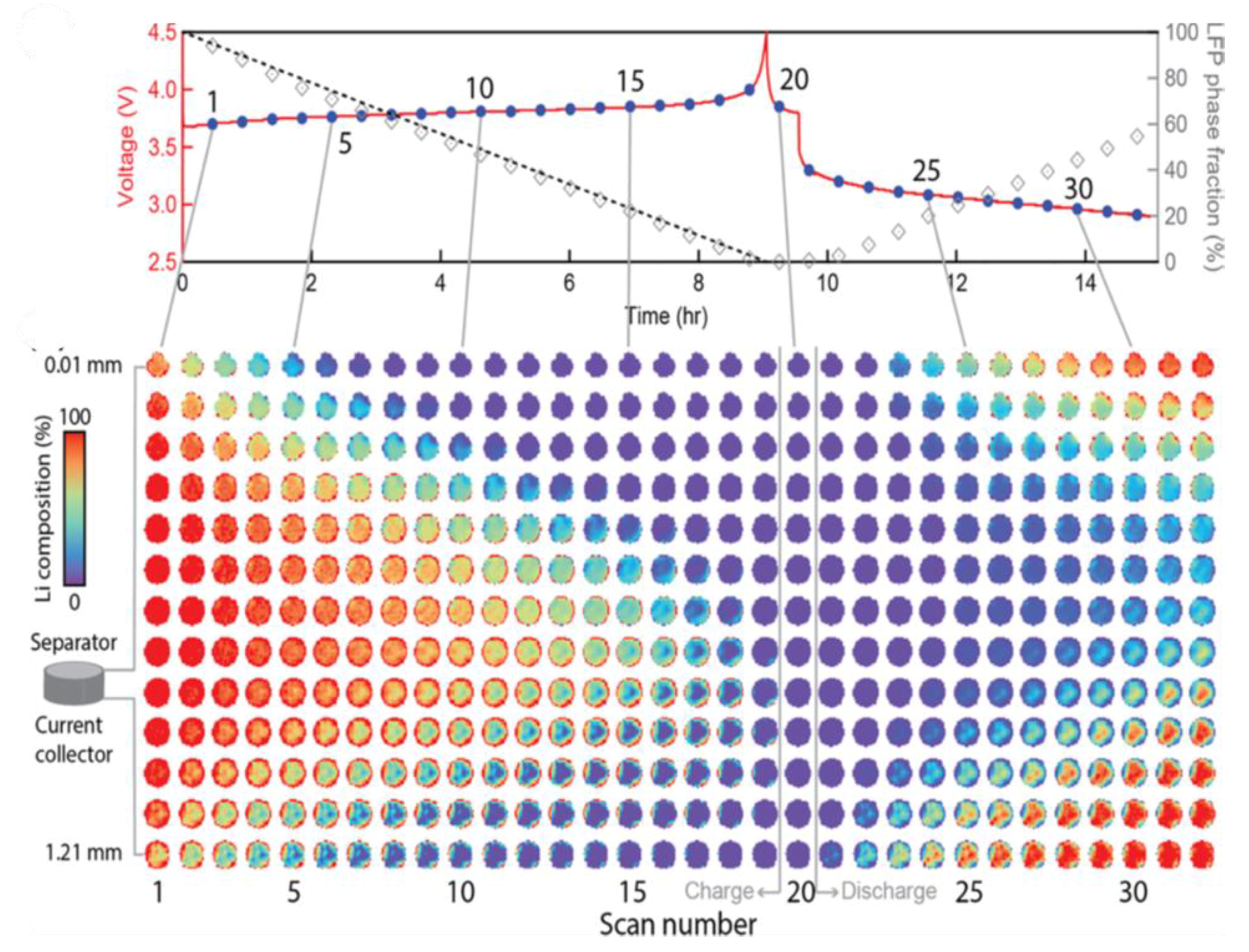
  40. Strobridge, F.C.; Orvananos, B.; Croft, M.; Yu, H.C.; Robert, R.; Liu, H.; Zhong, Z.; Connolley, T.; Drakopoulos, M.; Thornton, K.; et al. Mapping the inhomogeneous electrochemical reaction through porous LiFePO4-electrodes in a standard coin cell battery. Chem. Mater. 2015, 27, 2374–2386. [Google Scholar] [CrossRef] [Green Version]
  41. Ronci, F.; Scrosati, B.; Rossi Albertini, V.; Perfetti, P. In situ energy dispersive x-ray diffraction study of LiNi0.8Co0.2O2 cathode material for lithium batteries. J. Phys. Chem. B 2001, 105, 754–759. [Google Scholar] [CrossRef]
  42. Marschilok, A.C.; Bruck, A.M.; Abraham, A.; Stackhouse, C.A.; Takeuchi, K.J.; Takeuchi, E.S.; Croft, M.; Gallaway, J.W. Energy dispersive X-ray diffraction (EDXRD) for operando materials characterization within batteries. Phys. Chem. Chem. Phys. 2020, 22, 20972–20989. [Google Scholar] [CrossRef]
  43. Xu, Y.; Hu, E.; Zhang, K.; Wang, X.; Borzenets, V.; Sun, Z.; Pianetta, P.; Yu, X.; Liu, Y.; Yang, X.Q.; et al. In situ Visualization of State-of-Charge Heterogeneity within a LiCoO2 Particle that Evolves upon Cycling at Different Rates. ACS Energy Lett. 2017, 2, 1240–1245. [Google Scholar] [CrossRef]
  44. Holleck, G.L.; Driscoll, J.R. Transition metal sulfides as cathodes for secondary lithium batteries-II. titanium sulfides. Electrochim. Acta 1977, 22, 647–655. [Google Scholar] [CrossRef]
  45. Dahn, J.R.; Haering, R.R. Anomalous bragg peak widths in LixTiS2. Solid State Commun. 1981, 40, 245–248. [Google Scholar] [CrossRef]
  46. Ghanty, C.; Markovsky, B.; Erickson, E.M.; Talianker, M.; Haik, O.; Tal-Yossef, Y.; Mor, A.; Aurbach, D.; Lampert, J.; Volkov, A.; et al. Li+-Ion Extraction/Insertion of Ni-Rich Li1+x(NiyCozMnz)wO2 (0.005 < x < 0.03; y:z = 8:1, w ≈ 1) Electrodes: In Situ XRD and Raman Spectroscopy Study. ChemElectroChem 2015, 2, 1479–1486. [Google Scholar] [CrossRef]
  47. Yavuz, M.; Kiziltas-Yavuz, N.; Bhaskar, A.; Scheuermann, M.; Indris, S.; Fauth, F.; Knapp, M.; Ehrenberg, H. Influence of iron on the structural evolution of Lini0.4Fe0.2MN1.4O4 during electrochemical cycling investigated by in situ powder diffraction and spectroscopic methods. Z. Anorg. Allg. Chem. 2014, 640, 3118–3126. [Google Scholar] [CrossRef]
  48. Herklotz, M.; Scheiba, F.; Hinterstein, M.; Nikolowski, K.; Knapp, M.; Dippel, A.C.; Giebeler, L.; Eckert, J.; Ehrenberg, H. Advances in in situ powder diffraction of battery materials: A case study of the new beamline P02.1 at DESY, Hamburg. J. Appl. Crystallogr. 2013, 46, 1117–1127. [Google Scholar] [CrossRef]
  49. Schweidler, S.; De Biasi, L.; Schiele, A.; Hartmann, P.; Brezesinski, T.; Janek, J. Volume Changes of Graphite Anodes Revisited: A Combined Operando X-ray Diffraction and in Situ Pressure Analysis Study. J. Phys. Chem. C 2018, 122, 8829–8835. [Google Scholar] [CrossRef]
  50. De Biasi, L.; Kondrakov, A.O.; Geßwein, H.; Brezesinski, T.; Hartmann, P.; Janek, J. Between Scylla and Charybdis: Balancing among Structural Stability and Energy Density of Layered NCM Cathode Materials for Advanced Lithium-Ion Batteries. J. Phys. Chem. C 2017, 121, 26163–26171. [Google Scholar] [CrossRef]
  51. Borkiewicz, O.J.; Shyam, B.; Wiaderek, K.M.; Kurtz, C.; Chupas, P.J.; Chapman, K.W. The AMPIX electrochemical cell: A versatile apparatus for in situ X-ray scattering and spectroscopic measurements. J. Appl. Crystallogr. 2012, 45, 1261–1269. [Google Scholar] [CrossRef]
  52. Nikolowski, K.; Baehtz, G.; Bramnik, N.N.; Ehrenberg, H. A Swagelok-type in situ cell for battery investigations using synchrotron radiation. J. Appl. Crystallogr. 2005, 38, 851–853. [Google Scholar] [CrossRef]
  53. Leriche, J.B.; Hamelet, S.; Shu, J.; Morcrette, M.; Masquelier, C.; Ouvrard, G.; Zerrouki, M.; Soudan, P.; Belin, S.; Elkaïm, E.; et al. An Electrochemical Cell for Operando Study of Lithium Batteries Using Synchrotron Radiation. J. Electrochem. Soc. 2010, 157, A606. [Google Scholar] [CrossRef]
  54. Liu, H.; Allan, P.K.; Borkiewicz, O.J.; Kurtz, C.; Grey, C.P.; Chapman, K.W.; Chupas, P.J. A radially accessible tubular in situ X-ray cell for spatially resolved operando scattering and spectroscopic studies of electrochemical energy storage devices. J. Appl. Crystallogr. 2016, 49, 1665–1673. [Google Scholar] [CrossRef]
  55. Klein, D.; Xu, Y.; Schlögl, R.; Cap, S. Low Reversible Capacity of Nitridated Titanium Electrical Terminals. Batteries 2019, 5, 17. [Google Scholar] [CrossRef] [Green Version]
  56. Wilson, G.; Zilinskaite, S.; Unka, S.; Boston, R.; Reeves-McLaren, N. Establishing operando diffraction capability through the study of Li-ion (de) intercalation in LiFePO4. Energy Rep. 2020, 6, 174–179. [Google Scholar] [CrossRef]
  57. Yu, F.; Zhang, L.; Li, Y.; An, Y.; Zhu, M.; Dai, B. Mechanism studies of LiFePO4 cathode material: Lithiation/delithiation process, electrochemical modification and synthetic reaction. RSC Adv. 2014, 4, 54576–54602. [Google Scholar] [CrossRef]
  58. Quilty, C.D.; Bock, D.C.; Yan, S.; Takeuchi, K.J.; Takeuchi, E.S.; Marschilok, A.C. Probing Sources of Capacity Fade in LiNi0.6Mn0.2Co0.2O2 (NMC622): An Operando XRD Study of Li/NMC622 Batteries during Extended Cycling. J. Phys. Chem. C 2020, 124, 8119–8128. [Google Scholar] [CrossRef]
  59. Hulbert, S.L.; Williams, G.P. 1—Synchrotron Radiation Sources; Samson, J.A.R., Ederer, D.L., Eds.; Academic Press: Burlington, VT, USA, 2000; pp. 1–25. ISBN 978-0-12-617560-8. [Google Scholar]
  60. Beale, A.M.; Jacques, S.D.M.; Gibson, E.K.; Di Michiel, M. Progress towards five dimensional diffraction imaging of functional materials under process conditions. Coord. Chem. Rev. 2014, 277, 208–223. [Google Scholar] [CrossRef]
  61. Bianchini, M.; Fauth, F.; Brisset, N.; Weill, F.; Suard, E.; Masquelier, C.; Croguennec, L. Comprehensive investigation of the Na3V2(PO4)2F3-NaV2(PO4)2F3 system by operando high resolution synchrotron X-ray diffraction. Chem. Mater. 2015, 27, 3009–3020. [Google Scholar] [CrossRef]
  62. Bianchini, M.; Brisset, N.; Fauth, F.; Weill, F.; Elkaim, E.; Suard, E.; Masquelier, C.; Croguennec, L. Na3V2(PO4)2F3 revisited: A high-resolution diffraction study. Chem. Mater. 2014, 26, 4238–4247. [Google Scholar] [CrossRef]
  63. Withers, P.J. Depth capabilities of neutron and synchrotron diffraction strain measurement instruments. I. The maximum feasible path length. J. Appl. Crystallogr. 2004, 37, 596–606. [Google Scholar] [CrossRef]
  64. Young, B.T.; Heskett, D.R.; Woicik, J.C.; Lucht, B.L. X-ray-induced changes to passivation layers of lithium-ion battery electrodes. J. Spectrosc. 2018, 2018. [Google Scholar] [CrossRef]
  65. Xu, C.; Märker, K.; Lee, J.; Mahadevegowda, A.; Reeves, P.J.; Day, S.J.; Groh, M.F.; Emge, S.P.; Ducati, C.; Layla Mehdi, B.; et al. Bulk fatigue induced by surface reconstruction in layered Ni-rich cathodes for Li-ion batteries. Nat. Mater. 2020. [Google Scholar] [CrossRef] [PubMed]
  66. Marker, K.; Reeves, P.J.; Xu, C.; Griffith, K.J.; Grey, C.P. Evolution of structure and lithium dynamics in LiNi0.8Mn0.1Co0.1O2 (NMC811) cathodes during electrochemical cycling. Chem. Mater. 2019, 2, 2545–2554. [Google Scholar] [CrossRef]
  67. Bartsch, T.; Kim, A.Y.; Strauss, F.; De Biasi, L.; Teo, J.H.; Janek, J.; Hartmann, P.; Brezesinski, T. Indirect state-of-charge determination of all-solid-state battery cells by X-ray diffraction. Chem. Commun. 2019, 55, 11223–11226. [Google Scholar] [CrossRef] [PubMed] [Green Version]
  68. Oh, G.; Hirayama, M.; Kwon, O.; Suzuki, K.; Kanno, R. Bulk-Type All Solid-State Batteries with 5 v Class LiNi0.5Mn1.5O4 Cathode and Li10GeP2S12 Solid Electrolyte. Chem. Mater. 2016, 28, 2634–2640. [Google Scholar] [CrossRef]
  69. Chattopadhyay, S.; Lipson, A.L.; Karmel, H.J.; Emery, J.D.; Fister, T.T.; Fenter, P.A.; Hersam, M.C.; Bedzyk, M.J. In situ X-ray study of the solid electrolyte interphase (SEI) formation on graphene as a model Li-ion battery anode. Chem. Mater. 2012, 24, 3038–3043. [Google Scholar] [CrossRef]
  70. Tippens, J.; Miers, J.C.; Afshar, A.; Lewis, J.A.; Cortes, F.J.Q.; Qiao, H.; Marchese, T.S.; Di Leo, C.V.; Saldana, C.; McDowell, M.T. Visualizing Chemomechanical Degradation of a Solid-State Battery Electrolyte. ACS Energy Lett. 2019, 4, 1475–1483. [Google Scholar] [CrossRef]
  71. Bianchini, M.; Fauth, F.; Suard, E.; Leriche, J.B.; Masquelier, C.; Croguennec, L. Spinel materials for Li-ion batteries: New insights obtained by operando neutron and synchrotron X-ray diffraction. Acta Crystallogr. Sect. B Struct. Sci. Cryst. Eng. Mater. 2015, 71, 688–701. [Google Scholar] [CrossRef] [Green Version]
  72. Lu, Z.; MacNeil, D.D.; Dahn, J.R. Layered cathode materials Li[NixLi(1/3−2x/3)Mn(2/3−x/3)]O2 for lithium-ion batteries. Electrochem. Solid-State Lett. 2001, 4, 3–7. [Google Scholar] [CrossRef]
  73. Bie, X.; Du, F.; Wang, Y.; Zhu, K.; Ehrenberg, H.; Nikolowski, K.; Wang, C.; Chen, G.; Wei, Y. Relationships between the crystal/interfacial properties and electrochemical performance of LiNi0.33Co0.33Mn0.33O2 in the voltage window of 2.5–4.6 v. Electrochim. Acta 2013, 97, 357–363. [Google Scholar] [CrossRef]
  74. He, P.; Yu, H.; Li, D.; Zhou, H. Layered lithium transition metal oxide cathodes towards high energy lithium-ion batteries. J. Mater. Chem. 2012, 22, 3680–3695. [Google Scholar] [CrossRef]
  75. Li, M.; Lu, J.; Chen, Z.; Amine, K. 30 Years of Lithium-Ion Batteries. Adv. Mater. 2018, 1800561, 1800561. [Google Scholar] [CrossRef] [PubMed] [Green Version]
  76. Yin, L.; Li, Z.; Mattei, G.S.; Zheng, J.; Zhao, W.; Omenya, F.; Fang, C.; Li, W.; Li, J.; Xie, Q.; et al. Thermodynamics of Antisite Defects in Layered NMC Cathodes: Systematic Insights from High-Precision Powder Diffraction Analyses. Chem. Mater. 2020, 32, 1002–1010. [Google Scholar] [CrossRef] [Green Version]
  77. William, C. Crystal Structure Determination; Oxford University Press: New York, NY, USA, 1998. [Google Scholar]
  78. William, C. X-Ray Crystallography; Oxford University Press: New York, NY, USA, 2014. [Google Scholar]
  79. Li, L.; Xie, Y.; Maxey, E.; Harder, R. Methods for operando coherent X-ray diffraction of battery materials at the Advanced Photon Source. J. Synchrotron Radiat. 2019, 26, 220–229. [Google Scholar] [CrossRef] [PubMed]
  80. Singer, A.; Zhang, M.; Hy, S.; Cela, D.; Fang, C.; Wynn, T.A.; Qiu, B.; Xia, Y.; Liu, Z.; Ulvestad, A.; et al. Nucleation of dislocations and their dynamics in layered oxide cathode materials during battery charging. Nat. Energy 2018, 3, 641–647. [Google Scholar] [CrossRef]
  81. Liu, D.; Shadike, Z.; Lin, R.; Qian, K.; Li, H.; Li, K.; Wang, S.; Yu, Q.; Liu, M.; Ganapathy, S.; et al. Review of Recent Development of In Situ/Operando Characterization Techniques for Lithium Battery Research. Adv. Mater. 2019, 31, 1–57. [Google Scholar] [CrossRef]
  82. Singer, A.; Ulvestad, A.; Cho, H.M.; Kim, J.W.; Maser, J.; Harder, R.; Meng, Y.S.; Shpyrko, O.G. Nonequilibrium structural dynamics of nanoparticles in LiNi1/2Mn3/2O4 cathode under operando conditions. Nano Lett. 2014, 14, 5295–5300. [Google Scholar] [CrossRef] [Green Version]
  83. Ehi-Eromosele, C.O.; Indris, S.; Bramnik, N.N.; Sarapulova, A.; Trouillet, V.; Pfaffman, L.; Melinte, G.; Mangold, S.; Darma, M.S.D.; Knapp, M.; et al. In Situ X-ray Diffraction and X-ray Absorption Spectroscopic Studies of a Lithium-Rich Layered Positive Electrode Material: Comparison of Composite and Core-Shell Structures. ACS Appl. Mater. Interfaces 2020, 12, 13852–13868. [Google Scholar] [CrossRef]
  84. Nayak, P.K.; Yang, L.; Pollok, K.; Langenhorst, F.; Aurbach, D.; Adelhelm, P. Investigation of Li1.17Ni0.20Mn0.53Co0.10O2 as an Interesting Li- and Mn-Rich Layered Oxide Cathode Material through Electrochemistry, Microscopy, and In Situ Electrochemical Dilatometry. Chem. Electro. Chem. 2019, 6, 2812–2819. [Google Scholar] [CrossRef]
  85. Ulvestad, A.; Singer, A.; Clark, J.N.; Cho, H.M.; Kim, J.W.; Harder, R.; Maser, J.; Meng, Y.S.; Shpyrko, O.G. Topological defect dynamics in operando battery nanoparticles. Science 2015, 348, 1344–1348. [Google Scholar] [CrossRef] [Green Version]
  86. You, H.; Liu, Y.; Ulvestad, A.; Pierce, M.S.; Komanicky, V. Studies of electrode structures and dynamics using coherent X-ray scattering and imaging. Curr. Opin. Electrochem. 2017, 4, 89–94. [Google Scholar] [CrossRef]
  87. Sottmann, J.; Homs-Regojo, R.; Wragg, D.S.; Fjellvåg, H.; Margadonna, S.; Emerich, H. Versatile electrochemical cell for Li/Na-ion batteries and high-throughput setup for combined operando X-ray diffraction and absorption spectroscopy. J. Appl. Crystallogr. 2016, 49, 1972–1981. [Google Scholar] [CrossRef] [Green Version]
  88. Braun, A.; Nordlund, D.; Song, S.W.; Huang, T.W.; Sokaras, D.; Liu, X.; Yang, W.; Weng, T.C.; Liu, Z. Hard X-rays in-soft X-rays out: An operando piggyback view deep into a charging lithium ion battery with X-ray Raman spectroscopy. J. Electron Spectros. Relat. Phenomena 2015, 200, 257–263. [Google Scholar] [CrossRef] [Green Version]
  89. Li, T.; Lim, C.; Cui, Y.; Zhou, X.; Kang, H.; Yan, B.; Meyerson, M.L.; Weeks, J.A.; Liu, Q.; Guo, F.; et al. In situ and operando investigation of the dynamic morphological and phase changes of a selenium-doped germanium electrode during (de)lithiation processes. J. Mater. Chem. A 2020, 8, 750–759. [Google Scholar] [CrossRef]
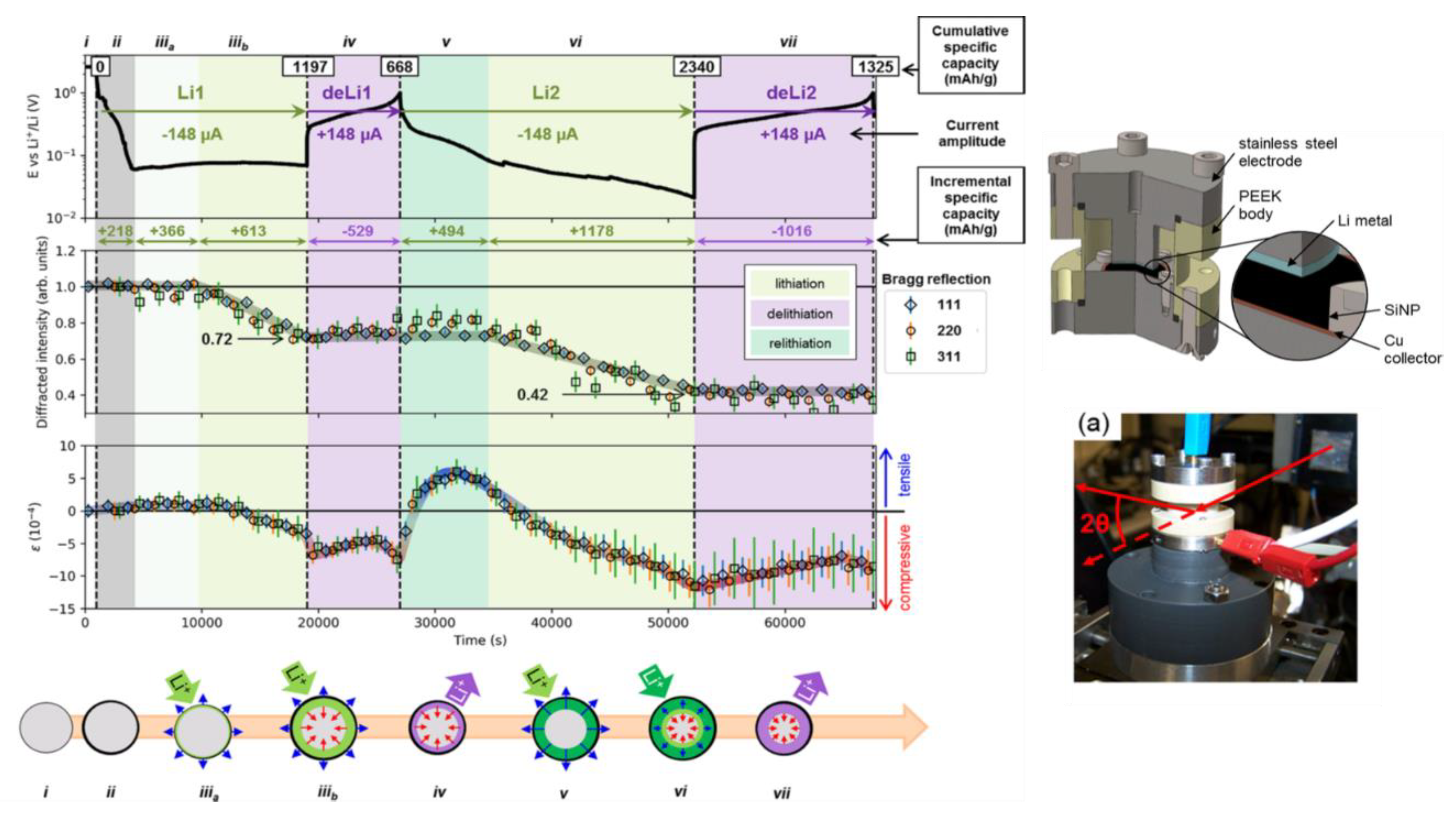
  90. Tardif, S.; Pavlenko, E.; Quazuguel, L.; Boniface, M.; Maréchal, M.; Micha, J.S.; Gonon, L.; Mareau, V.; Gebel, G.; Bayle-Guillemaud, P.; et al. Operando Raman Spectroscopy and Synchrotron X-ray Diffraction of Lithiation/Delithiation in Silicon Nanoparticle Anodes. ACS Nano 2017, 11, 11306–11316. [Google Scholar] [CrossRef] [PubMed]
  91. Nonaka, T.; Kawaura, H.; Makimura, Y.; Nishimura, Y.F.; Dohmae, K. In situ X-ray Raman scattering spectroscopy of a graphite electrode for lithium-ion batteries. J. Power Sources 2019, 419, 203–207. [Google Scholar] [CrossRef]
  92. Mukai, K.; Nonaka, T.; Uyama, T.; Nishimura, Y.F. In situ X-ray Raman spectroscopy and magnetic susceptibility study on the Li[Li0.15Mn1.85]O4 oxygen anion redox reaction. Chem. Commun. 2020, 56, 1701–1704. [Google Scholar] [CrossRef] [PubMed]
  93. Ketenoglu, D.; Spiekermann, G.; Harder, M.; Oz, E.; Koz, C.; Yagci, M.C.; Yilmaz, E.; Yin, Z.; Sahle, C.J.; Detlefs, B.; et al. X-ray Raman spectroscopy of lithium-ion battery electrolyte solutions in a flow cell. J. Synchrotron Radiat. 2018, 25, 537–542. [Google Scholar] [CrossRef] [Green Version]
  94. Wang, F.; Yu, H.C.; Chen, M.H.; Wu, L.; Pereira, N.; Thornton, K.; Van Der Ven, A.; Zhu, Y.; Amatucci, G.G.; Graetz, J. Tracking lithium transport and electrochemical reactions in nanoparticles. Nat. Commun. 2012, 3, 1–8. [Google Scholar] [CrossRef] [Green Version]
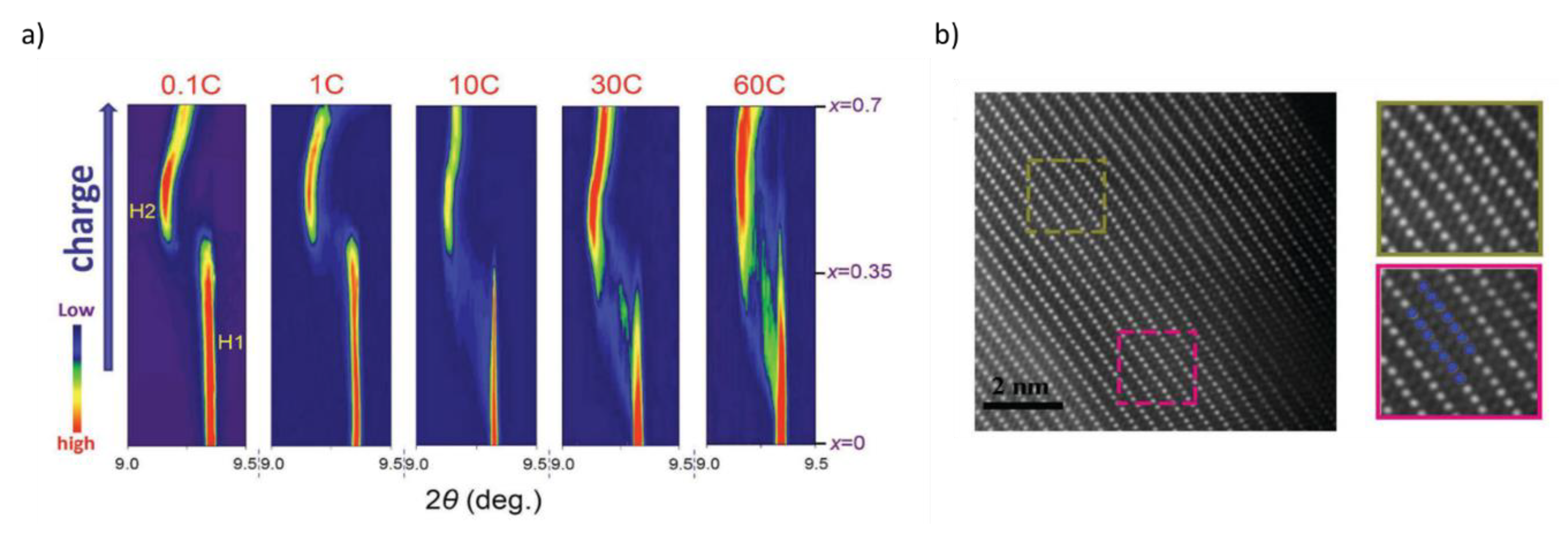
  95. Zhou, Y.N.; Yue, J.L.; Hu, E.; Li, H.; Gu, L.; Nam, K.W.; Bak, S.M.; Yu, X.; Liu, J.; Bai, J.; et al. High-Rate Charging Induced Intermediate Phases and Structural Changes of Layer-Structured Cathode for Lithium-Ion Batteries. Adv. Energy Mater. 2016, 6, 1–8. [Google Scholar] [CrossRef]
  96. Nelson, J.; Misra, S.; Yang, Y.; Jackson, A.; Liu, Y.; Wang, H.; Dai, H.; Andrews, J.C.; Cui, Y.; Toney, M.F. In operando X-ray diffraction and transmission X-ray microscopy of lithium sulfur batteries. J. Am. Chem. Soc. 2012, 134, 6337–6343. [Google Scholar] [CrossRef]
  97. Chueh, W.C.; El Gabaly, F.; Sugar, J.D.; Bartelt, N.C.; McDaniel, A.H.; Fenton, K.R.; Zavadil, K.R.; Tyliszczak, T.; Lai, W.; McCarty, K.F. Intercalation pathway in many-particle LiFePO4 electrode revealed by nanoscale state-of-charge mapping. Nano Lett. 2013, 13, 866–872. [Google Scholar] [CrossRef] [PubMed]
  98. Li, Y.; El Gabaly, F.; Ferguson, T.R.; Smith, R.B.; Bartelt, N.C.; Sugar, J.D.; Fenton, K.R.; Cogswell, D.A.; Kilcoyne, A.L.D.; Tyliszczak, T.; et al. Current-induced transition from particle-by-particle to concurrent intercalation in phase-separating battery electrodes. Nat. Mater. 2014, 13, 1149–1156. [Google Scholar] [CrossRef] [PubMed]
  99. Yang, F.; Liu, Y.; Martha, S.K.; Wu, Z.; Andrews, J.C.; Ice, G.E.; Pianetta, P.; Nanda, J. Nanoscale morphological and chemical changes of high voltage lithium-manganese rich NMC composite cathodes with cycling. Nano Lett. 2014, 14, 4334–4341. [Google Scholar] [CrossRef] [PubMed] [Green Version]
  100. Yu, S.H.; Huang, X.; Schwarz, K.; Huang, R.; Arias, T.A.; Brock, J.D.; Abruña, H.D. Direct visualization of sulfur cathodes: New insights into Li-S batteries via operando X-ray based methods. Energy Environ. Sci. 2018, 11, 202–210. [Google Scholar] [CrossRef]
  101. Xie, Y.; Wang, H.; Xu, G.; Wang, J.; Sheng, H.; Chen, Z.; Ren, Y.; Sun, C.J.; Wen, J.; Wang, J.; et al. In Operando XRD and TXM Study on the Metastable Structure Change of NaNi1/3Fe1/3Mn1/3O2 under Electrochemical Sodium-Ion Intercalation. Adv. Energy Mater. 2016, 6, 3–7. [Google Scholar] [CrossRef]
  102. Thomas, M.M.; Heenan, A.W.; Chun, T.; Julia, E.; Parker, D.M.; Andrew, S.; Leach, J.B.; Robinson, A.L.; Alexander, D.; Rhodri, J.; et al. Identifying the Origins of Microstructural Defects Such as Cracking within Ni-Rich NMC811 Cathode Particles for Lithium-ion Batteries. Adv. Energy Mater. 2020. [Google Scholar] [CrossRef]
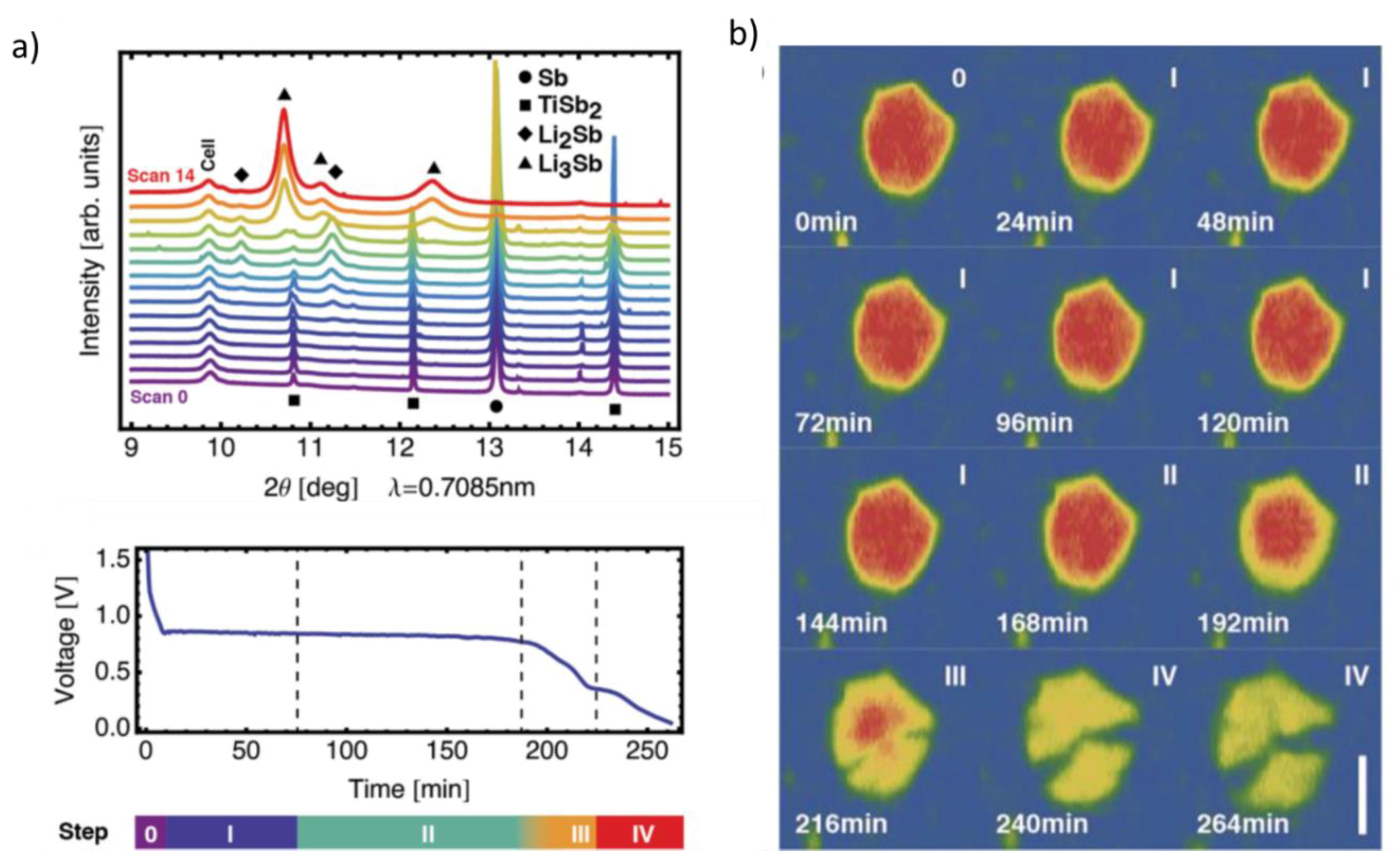
  103. Villevieille, C.; Ebner, M.; Gómez-Cámer, J.L.; Marone, F.; Novák, P.; Wood, V. Influence of conversion material morphology on electrochemistry studied with operando X-ray tomography and diffraction. Adv. Mater. 2015, 27, 1676–1681. [Google Scholar] [CrossRef]
  104. Finegan, D.P.; Vamvakeros, A.; Tan, C.; Heenan, T.M.M.; Daemi, S.R.; Seitzman, N.; Di Michiel, M.; Jacques, S.; Beale, A.M.; Brett, D.J.L.; et al. Spatial quantification of dynamic inter and intra particle crystallographic heterogeneities within lithium ion electrodes. Nat. Commun. 2020, 11, 1–11. [Google Scholar] [CrossRef] [Green Version]
  105. Bleuet, P.; Susini, J.; Hodeau, J.; Eonore, E.L.; Ee, E.D.; Walter, P. Probing the structure of heterogeneous diluted materials by diffraction to mography. Nat. Mater. 2008, 7. [Google Scholar] [CrossRef]
  106. Daemi, S.R.; Tan, C.; Vamvakeros, A.; Heenan, T.M.M.; Finegan, D.P.; Di Michiel, M.; Beale, A.M.; Cookson, J.; Petrucco, E.; Weaving, J.S.; et al. Exploring cycling induced crystallographic change in NMC with X-ray diffraction computed tomography. Phys. Chem. Chem. Phys. 2020. [Google Scholar] [CrossRef]
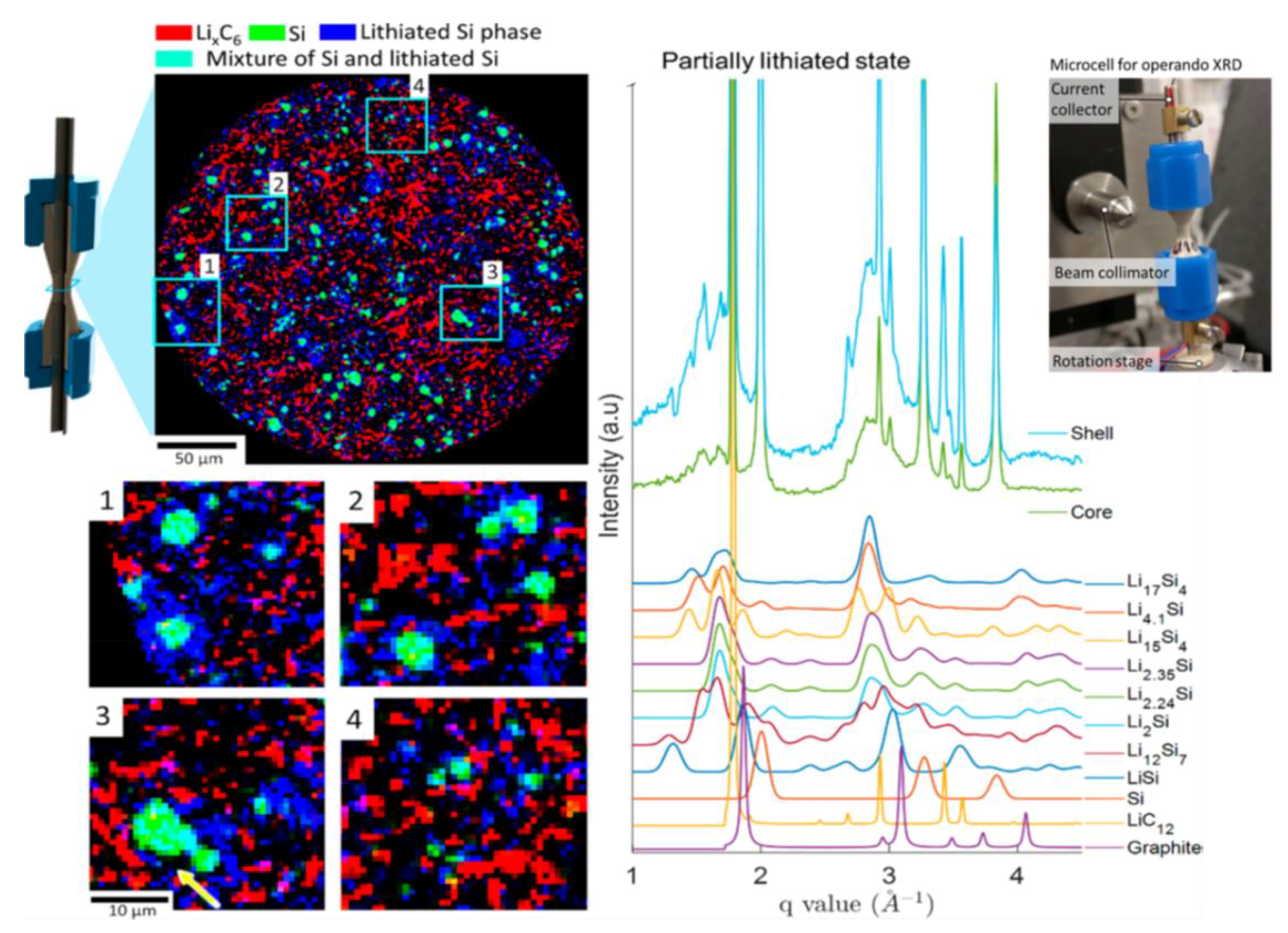
  107. Finegan, D.P.; Vamvakeros, A.; Cao, L.; Tan, C.; Heenan, T.M.M.; Daemi, S.R.; Jacques, S.D.M.; Beale, A.M.; Di Michiel, M.; Smith, K.; et al. Spatially Resolving Lithiation in Silicon-Graphite Composite Electrodes via in Situ High-Energy X-ray Diffraction Computed Tomography. Nano Lett. 2019, 19, 3811–3820. [Google Scholar] [CrossRef] [PubMed]
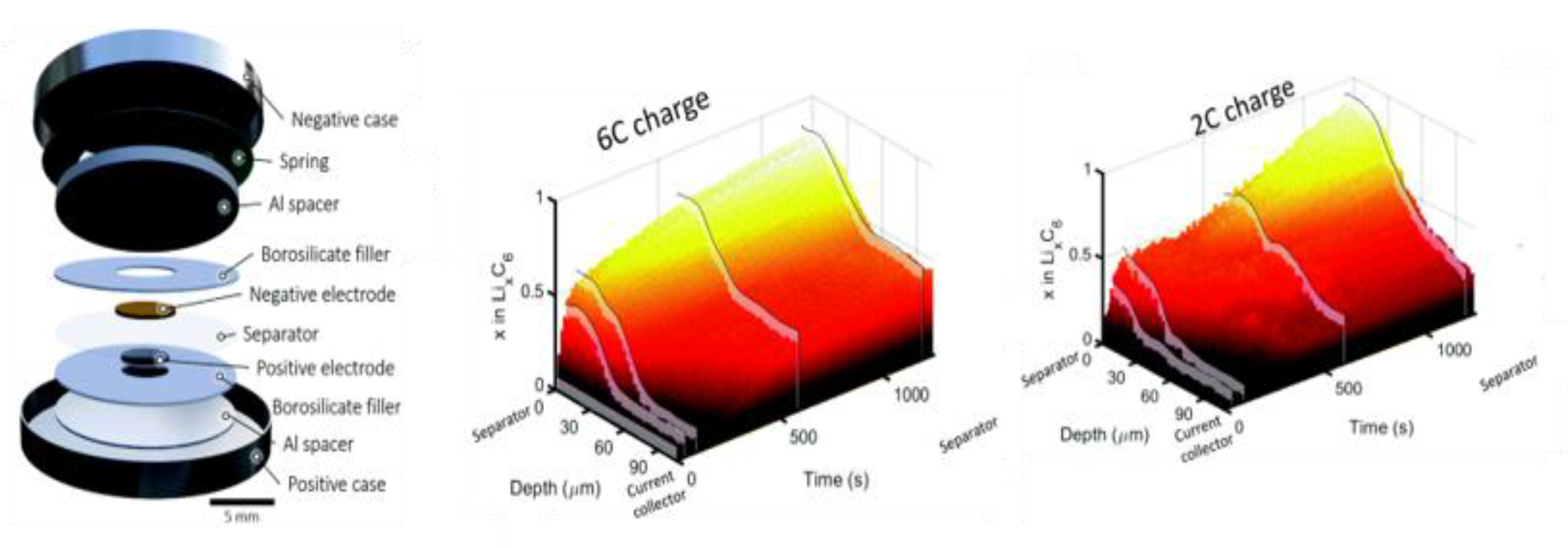
  108. Liu, H.; Kazemiabnavi, S.; Grenier, A.; Vaughan, G.; Di Michiel, M.; Polzin, B.J.; Thornton, K.; Chapman, K.W.; Chupas, P.J. Quantifying Reaction and Rate Heterogeneity in Battery Electrodes in 3D through Operando X-ray Diffraction Computed Tomography. ACS Appl. Mater. Interfaces 2019, 11, 18386–18394. [Google Scholar] [CrossRef] [PubMed]
  109. Vanpeene, V.; King, A.; Maire, E.; Roué, L. In situ characterization of Si-based anodes by coupling synchrotron X-ray tomography and diffraction. Nano Energy 2019, 56, 799–812. [Google Scholar] [CrossRef]
  110. Lemarié, Q.; Maire, E.; Idrissi, H.; Thivel, P.X.; Alloin, F.; Roué, L. Sulfur-Based Electrode Using a Polyelectrolyte Binder Studied via Coupled in Situ Synchrotron X-ray Diffraction and Tomography. ACS Appl. Energy Mater. 2020, 3, 2422–2431. [Google Scholar] [CrossRef]
  111. Finegan, D.P.; Quinn, A.; Wragg, D.S.; Colclasure, A.M.; Lu, X.; Tan, C.; Heenan, T.M.M.; Jervis, R.; Brett, D.J.L.; Das, S.; et al. Spatial dynamics of lithiation and lithium plating during high-rate operation of graphite electrodes. Energy Environ. Sci. 2020. [Google Scholar] [CrossRef]
  112. Ren, Y.; Zuo, X. Synchrotron X-Ray and Neutron Diffraction, Total Scattering, and Small-Angle Scattering Techniques for Rechargeable Battery Research. Small Methods 2018, 2, 1800064. [Google Scholar] [CrossRef]
  113. Permien, S.; Hansen, A.L.; Van Dinter, J.; Indris, S.; Neubüser, G.; Kienle, L.; Doyle, S.; Mangold, S.; Bensch, W. Unveiling the Reaction Mechanism during Li Uptake and Release of Nanosized “niFeMnO4”: Operando X-ray Absorption, X-ray Diffraction, and Pair Distribution Function Investigations. ACS Omega 2019, 4, 2398–2409. [Google Scholar] [CrossRef]
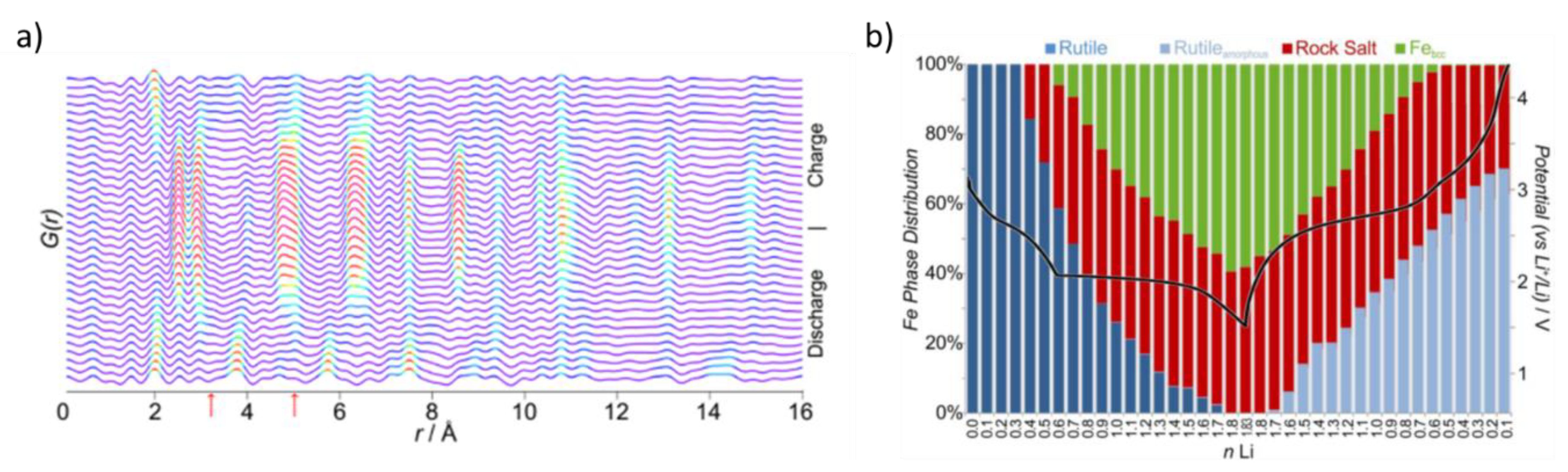
  114. Wiaderek, K.M.; Borkiewicz, O.J.; Castillo-Martínez, E.; Robert, R.; Pereira, N.; Amatucci, G.G.; Grey, C.P.; Chupas, P.J.; Chapman, K.W. Comprehensive insights into the structural and chemical changes in mixed-anion FeOF electrodes by using operando pdf and NMR spectroscopy. J. Am. Chem. Soc. 2013, 135, 4070–4078. [Google Scholar] [CrossRef]
  115. Benmore, C.J. A Review of High-Energy X-Ray Diffraction from Glasses and Liquids. ISRN Mater. Sci. 2012, 2012, 1–19. [Google Scholar] [CrossRef]
  116. Hong, X.; Ehm, L.; Zhong, Z.; Ghose, S.; Duffy, T.S.; Weidner, D.J. High-energy X-ray focusing and applications to pair distribution function investigation of Pt and Au nanoparticles at high pressures. Sci. Rep. 2016, 6, 1–8. [Google Scholar] [CrossRef] [Green Version]
  117. Poulsen, H.F.; Neuefeind, J.; Neumann, H.B.; Schneider, J.R.; Zeidler, M.D. Amorphous silica studied by high energy X-ray diffraction. J. Non. Cryst. Solids 1995, 188, 63–74. [Google Scholar] [CrossRef]
  118. Sánchez-Gil, V.; Noya, E.G.; Temleitner, L.; Pusztai, L. Reverse Monte Carlo modeling: The two distinct routes of calculating the experimental structure factor. J. Mol. Liq. 2015, 207, 211–215. [Google Scholar] [CrossRef] [Green Version]
  119. Eremenko, M.; Krayzman, V.; Gagin, A.; Levin, I. Advancing reverse Monte Carlo structure refinements to the nanoscale. J. Appl. Crystallogr. 2017, 50, 1561–1570. [Google Scholar] [CrossRef]
  120. Soper, A.K. Tests of the empirical potential structure refinement method and a new method of application to neutron diffraction data on water. Mol. Phys. 2001, 99, 1503–1516. [Google Scholar] [CrossRef]
  121. Soper, A.K.; Page, K.; Llobet, A. Empirical potential structure refinement of semi-crystalline polymer systems: Polytetrafluoroethylene and polychlorotrifluoroethylene. J. Phys. Condens. Matter 2013, 25. [Google Scholar] [CrossRef] [Green Version]
  122. Pandey, A.; Biswas, P.; Drabold, D.A. Inversion of diffraction data for amorphous materials. Nat. Publ. Gr. 2016, 1–8. [Google Scholar] [CrossRef] [Green Version]
  123. Saito, Y.; Iihara, J.; Yamaguchi, K.; Haruna, T.; Onishi, M. Structure analysis technology for amorphous materials by synchrotron radiation X-ray measurements and molecular dynamics simulations. SEI Tech. Rev. 2008, 67, 27–32. [Google Scholar]
  124. Chao, W.; Fischer, P.; Tyliszczak, T.; Rekawa, S.; Anderson, E.; Naulleau, P. Real space soft x-ray imaging at 10 nm spatial resolution. Opt. Express 2012, 20, 9777. [Google Scholar] [CrossRef]
  125. Hill, J.; Campbell, S.; Carini, G.; Chen-Wiegart, Y.C.K.; Chu, Y.; Fluerasu, A.; Fukuto, M.; Idir, M.; Jakoncic, J.; Jarrige, I.; et al. Future trends in synchrotron science at NSLS-II. J. Phys. Condens. Matter 2020, 32, 374008. [Google Scholar] [CrossRef]
  126. Hatsui, T.; Graafsma, H. X-ray imaging detectors for synchrotron and XFEL sources. IUCrJ 2015, 2, 371–383. [Google Scholar] [CrossRef]
  127. Vaughan, G.B.M.; Baker, R.; Barret, R.; Bonnefoy, J.; Buslaps, T.; Checchia, S.; Duran, D.; Fihman, F.; Got, P.; Kieffer, J.; et al. ID15A at the ESRF-a beamline for high speed operando X-ray diffraction, diffraction tomography and total scattering. J. Synchrotron Radiat. 2020, 27, 515–528. [Google Scholar] [CrossRef] [PubMed]
Figure 1. (a) schematic of XRD working principle with an example of the obtained pattern; (b) schematic of the in situ cell developed by Chianelli and co-authors [25]; (c) schematic of the first developed in situ cell for transmission analysis [26]; (d) representation of the in situ cell developed by Amatucci and co-workers [27].
Condensedmatter 05 00075 g001
Figure 2. Experimental set up of the experiment, ED-XRD data obtained from 3 different coin cells (A) not discharged and (B,C) discharged to 0.5 electron equivalents at C/1440 at two different positions and (DF) discharged to 0.5 electron equivalents at C/168.
Condensedmatter 05 00075 g002
Figure 3. Designs of the most common used types of in-situ XRD cells: (a) modified coin cell, with photo (on the left) of the cell mounted on the sample holder on the powder diffraction beamline at the Australian Synchrotron [13]; (b) modified pouch cell with a Kapton film window [46]; (c) example of AMPIX cell from reference [51], reproduced with permission of the International Union of Crystallography; (d) schematic of a SwagelokTM type cells [55]; (e) photo (left) and design (right) of the SwagelokTM type cell described in [53]. The parts A, B and C compose the cylindrical plunger; (f) Schematic diagrams of a RATIX cell (left and middle images), with a cross section view (right image) [54], reproduced with permission of the International Union of Crystallography.
Condensedmatter 05 00075 g003
Figure 4. In situ diffraction results obtained for one cycle of LiFePO4 revealing the initial solid solution behaviour followed by the dual-phase behavior [56].
Condensedmatter 05 00075 g004
Figure 5. (a) Modified coin cell, (b) refined phase fractions obtained at different cycling intervals and (c) splitting of the 003 peak leading to the multiphase analysis adopted in the study [65].
Condensedmatter 05 00075 g005
Figure 6. Variation of antisite defect concentration (top row) or antisite defect fraction (bottom row) plotted as a function of the average nickel oxidation state (a,d), the fraction of nickel (Ni2+ and Ni3+) relative to the all transition metals (b,e) or the fraction of Ni2+ only relative to all the transition metals. The solid lines represent the line of best fit [76].
Condensedmatter 05 00075 g006
Figure 7. Rendering of cathode active material from the operando measurements during charge (a) at 4.0 V—a dislocation free crystal, (b) at 4.3 V and the presence of two dislocations, (c) 4.3 V and a formed dislocation network. The arrow labelled q indicates the direction of the X-ray scattering vector, perpendicular to the atomic layers [80].
Condensedmatter 05 00075 g007
Figure 8. (a) XRD-XAS Voltage profile with the evolution of the cubic lattice constants of the LiMn1.5Ni0.5O4 electrode (left), and Ni K edge XANES spectra of collected at the maximum phase fraction of the corresponding phases (middle). The image on the right shows a scheme of the used in-situ cell [87], reproduced with permission of the International Union of Crystallography; (b) XRD patterns of the Ge0.9Se0.1 electrode during the first cycle at 0.1C (upper left) and voltage profile (upper-right); selected germanium XANES (bottom-left) during lithiation (black solid) and delithiation (red dash) and Fourier Transforms of the EXAFS spectra during lithiation (black) and delithiation (red); on the right, scheme of the used in-situ cell [89].
Condensedmatter 05 00075 g008
Figure 9. Si NP-based anode time dependence of the cell potential (first graph), the X-ray diffraction intensity (second graph), the strain ε over the first two partial lithiation/delithiation cycles, (third graph), and cartoon representing the single-core−shell (first cycle) and double-core−shell (second cycle) mechanisms, compressive and tensile states [90];on the right: scheme of the used in-situ cell (top) and picture of the experimental set-up (bottom).
Condensedmatter 05 00075 g009
Figure 10. (a) 003 diffraction peak evolution of NMC cathode during the first charge; (b) TEM image taken along the [110] zone axis of the NMC electrode after 55 s charging at the current rate of 30 C, with zoom-in image of the areas marked with yellow and pink squares, respectively [95].
Condensedmatter 05 00075 g010
Figure 11. (a) operando XRD (upper) obtained for 14 scans during the first electrochemical reduction represented in the middle; colour map of the X-ray linear attenuation coefficients (bottom): the colour red can be associated with the high-density phases (i.e., Sb and TiSb2), the yellow–green with low-density phases (i.e., Li2Sb and Li3Sb), and the blue regions with weakly absorbing components of the electrode (i.e., carbon black, polymeric binder, and electrolyte); (b) X-ray tomograms of selected particles recorded every 24 min during lithiation. Scale bar: 20 μM.
Condensedmatter 05 00075 g011
Figure 12. XRD-CT of graphite-silicon composite electrode with phase-distribution map (upper-left image), with magnified regions of interests (bottom-left). On the right, the XRD pattern from segmented lithium silicide shells and Si cores. Adapted with permission from [107], copyright 2019 American Chemical Society.
Condensedmatter 05 00075 g012
Figure 13. XRD-CT voltage profile of a whole LFP electrode cycled at C/10 during operando XRD-CT (red curve); the bottom image shows the LFP phase fraction, i.e., the Li composition, map of different horizontal layers across the electrode during cycling [108].
Condensedmatter 05 00075 g013
Figure 14. (a) discharge/charge curves (left) and respective colour map XRD related to steps 1–24 (right); (b) lateral CT images at z ~5, 50 and 100 μM for different stages of cycling. The numbers 1–24 correspond to those indicated on the discharge/charge curves in (a); (c) schematic diagram of the used in-situ cell. Reprinted (adapted) with permission from [110].
Condensedmatter 05 00075 g014
Figure 15. Modified coin cell used in the XRD-CT experiment (left); 3D plot showing LiC6 value as a function of time and depth during 6C charge and 2C charge [111], published by The Royal Society of Chemistry.
Condensedmatter 05 00075 g015
Figure 16. (a) PDFs obtained during the first discharge−charge cycle (for x = 0.60, 50 °C, C/30, ∼35 h, 4.5–1.5–4.5 V). The arrows indicate distances characteristic of the rock salt intermediate. The colours reflect relative peak intensities; (b) evolution of Fe phases during cycling of x = 0.60 at 50 °C from full profile fits to the PDF data.
Condensedmatter 05 00075 g016
Publisher’s Note: MDPI stays neutral with regard to jurisdictional claims in published maps and institutional affiliations.

