Article

Design and Construction of a Novel Simple and Low-Cost Test Bench Point-Absorber Wave Energy Converter Emulator System

by
Ephraim Bonah Agyekum
1,*,
Seepana PraveenKumar
1,
Aleksei Eliseev
2 and
Vladimir Ivanovich Velkin
1
1
Department of Nuclear and Renewable Energy, Ural Federal University Named after the First President of Russia Boris, 19 Mira Street, 620002 Ekaterinburg, Russia
2
Ocean Rus Energy, Yubileynaya Street 1 Square 18, 623107 Pervouralsk, Russia
*
Author to whom correspondence should be addressed.
Submission received: 3 February 2021 / Revised: 15 March 2021 / Accepted: 18 March 2021 / Published: 22 March 2021
(This article belongs to the Special Issue Low-Cost Inventions and Patents)

Abstract

:
This paper proposed a test bench device to emulate or simulate the electrical impulses of a wave energy converter (WEC). The objective of the study is to reconstruct under laboratory conditions the dynamics of a WEC in the form of an emulator to assess the performance, which, in this case, is the output power. The designed emulator device is programmable, which makes it possible to create under laboratory conditions the operating mode of the wave generator, identical to how the wave generator would work under real sea conditions. Any control algorithm can be executed in the designed emulator. In order to test the performance of the constructed WEC emulator, an experiment was conducted to test its power output against that of a real point-absorber WEC. The results indicate that, although the power output for that of the real WEC was higher than the WEC emulator, the emulator performed perfectly well. The relatively low power output of the emulator was because of the type of algorithm that was written for the emulator, therefore increasing the speed of the motor in the algorithm (code) would result in higher output for the proposed WEC emulator.

1. Introduction

The need for a cleaner, cheaper and more reliable source of energy generation has led to increasing research in several renewable sources to assess their technoeconomic potential to meet global energy needs [1,2,3,4,5,6]. To meet this increasing demand for energy and also solve the issues related to reliability and availability, research on ocean wave energy has increased in recent times due to the huge energy potential it possesses [7,8]. Wave energy generation is at its initial stage of development and utilization; however, it presents lots of possibilities for the future due to its huge potential, relative to electricity production [9,10,11]. Research shows that the world’s wave energy resources are about 17 TW h/year, with the highest average wave power located in the mid-latitudes, i.e., between 30° and 60° [9]. Offshore wave power levels averaged over the years vary from 30 to 100 kW/m and are located in latitudes of 40–50°, as well as smaller power levels further north and south. The average wave power in most tropical waters is below 20 kW/m [12].
Research toward the design and development of appropriate conversion devices has been progressive over the years. The design of a particular wave energy converter (WEC) is usually dependent on the location of its installation in the sea [13,14]. A survey of WECs showed a variety of designs, namely: attenuators, oscillating water columns, point absorbers, wave surge converters, overtopping devices and submerged point absorbers. Each of these systems has its own unique power take-off (PTO) mechanisms and can introduce fluctuations in grid voltage as a result of their variable power output when connected to a distribution grid. The variability associated with it is basically a function of the intensity of the wave for a given time and the dominant wave period [15]. There are, however, some barriers that have affected the development and use of marine energies, such as uncertainties associated with impacts from the marine environment on the wave farms [9,16,17], immature technology [9,18] and the fact that these technologies are regarded as economically unviable [19].
Experimental testing of WECs is key in its development; however, sea trials are too expensive and time consuming, and as a result, it ought to be preceded by small- to medium-scale testing. Even though this does not give a full representation of the performance of the prototypes accurately, it provides important information to developers, researchers and investors/entrepreneurs. Testing of models is a critical step in the development of offshore renewable energy technologies (RETs). It consists of challenges that demand guidance and experience. Hence, costly mistakes could result in a waste of resources and time [20].
A number of studies have either theoretically, experimentally or numerically assessed the performance of wave energy converters. Têtu [21] gave guidelines toward the development of WECs; their study also provided some guidance on model testing for WECs. Tongphong et al. [22] presented a novel WEC known as the ModuleRaft WEC comprising a floating modular flap and four rafts hinged at the main floating structure. They investigated the motion characteristics, optimization and performance of the model under regular wave conditions with the ANSYS AQWA model. Results from their study suggested that the ModuleRaft WEC operates best by utilizing all directions of wave energy by using a single-point mooring system. Al Shami et al. [23] studied the impact of increasing the total number of degrees of freedom by adding submerged objects to a point-absorber WEC. This was aimed at capturing more power with a lower resonant frequency with the same total mass and volume, similar to that of a piezoelectric vibration energy harvester.
Furthermore, Muthukumar and Jayashankar [24] employed a permanent magnet synchronous generator based on adjustable speed energy extraction to operate an air turbine near its maximum power point operation. The study considered an Indian wave energy plant, wave period, typical wave height and differential pressure/wave power variation to conduct an offline computation of direct current bus voltage dynamics using a MATLAB-based transient model of a complete WEC. Blanco et al. [25] proposed a laboratory test bench for testing a direct-drive linear generator for integration into a WEC. Their study focused on getting a model for an actuator to generate the behavior of a WEC in a real sea environment. Hazra et al. [26] presented a paper on emulating dynamic WEC behavior using a real-time simulator, as well as an induction motor under test bed conditions. The emulator was made up of a WEC using NI CompactRIO, an induction motor and an electric drive. Wahyudie et al. [27] designed a laboratory-scale WEC system grounded on a planar double-sided permanent magnet linear generator. Their aim was to produce an easy and simple method in the design and optimization of the various parameters to realize the intended output voltage with physical design constraints.
Testing of WEC devices in a real sea environment is usually designed using test data obtained from prototype WECs in laboratories. Nevertheless, very little information is usually available in relation to which electrical arrangement and control system is the optimum for a WEC, as well as the possible power output of the WEC in a particular location beforehand, although some simulations can be done. However, according to [28], such simulations fall short of real data, and this is the research gap this study seeks to bridge. The objective of the current study is to reconstruct under laboratory conditions the dynamics of a WEC in the form of an emulator to assess its performance; in this case, the output power and other parameters depending on the input algorithm. The proposed WEC emulator device is programmable, which makes it possible to create in laboratory conditions the operating mode of the wave generator, identical to how the wave generator would work under real sea conditions. Any control algorithm can be executed in the designed emulator. This is a unique construction, and it is expected to help in laboratory sections, reducing the time required for testing and also cost.
The rest of the paper is presented as follows: Section 2 covers a brief description of wave energy characteristics. The methodology and materials used for the study are presented in Section 3. Section 4 covers the results and discussion, and the conclusions are presented in Section 5.

2. Description of Wave Energy Characteristics

There are several mechanisms that lead to the generation of ocean waves, some of which include planetary forces or earthquakes; however, most of them are prompted by wind blowing on the surface of the fluid, known as wind waves. The ocean’s depth and wavelength determine the velocity, which can be expressed using the dispersion relation (Equation (1)) [29]:
v = g λ 2 π t a n h ( 2 π h λ )
where the wavelength is represented by λ , the water depth is denoted by h (m) and g (m/s2) represents the acceleration due to gravity.
Research has shown that the diameter of the water particle motion circle declines with the water depth. Studies also indicate that nearly 95% of energy in waves can be found between the surface and the depth equivalent to a quarter of the deep-water wavelength [29,30]. A real sea wave may be regarded as a composition of several elementary waves with varying frequencies and directions, which is in contrast to that of a single-frequency sinusoidal wave moving in a specific direction. For a per unit area of the surface of a sea, stored energy equivalent to an average of Equation (2) is connected to the wave [12]:
E = ρ g H m 0 2 / 16 = ρ g 0 S ( f ) d f
where the mass density of the sea water is represented by ρ (kg/m3), H m 0 represents the significant wave height for the actual sea state and S(f) signifies the wave spectrum.
The total energy stored in waves is the summation of the potential E p and kinetic E k energies for every square meter, as expressed in Equation (3) [31].
E = E p + E k
The potential energy (PE) in relation to waves occurs as a result of the elevation of water, from the trough up to the crest. The average PE for each unit horizontal area can be computed using Equation (4) [31].
E p = ρ g 4 | A | 2 = ρ g 16 H 2 [ J m 2 ]
where A represents the amplitude, and H denotes the height.
The kinetic energy (KE) for each unit horizontal area can also be computed using Equation (5) [31].
E k = ρ 2 ω 2 | A | 2 0 e 2 k z d z = ρ 2 ω 2 2 k | A | 2   [ J m 2 ]
In situations where the deep-water conditions do not apply, ω 2 = g k t a n h ( k h ) is employed, hence the kinetic equation results in Equation (6) as
E k = ρ 4 | A | 2 g t a n h ( k h ) = ρ 16 H 2 g t a n h ( k h )
However, tanh ( k h ) 1 for deep water conditions, hence ω 2 = g k , and the equation thus becomes Equation (7).
E k = ρ g 4 | A | 2 = ρ g 16 H 2
Therefore, the total energy in the waves results in Equation (8).
E = E k + E p = ρ g H 2 16 ( 1 + t a n h ( k h ) )
Equation (3) becomes Equation (9) under deep-water conditions.
E = E k + E p = ρ g H 2 8

2.1. Extraction of Wave Energy

The conversion of wave energy is a varying stochastic process as a result of radiation and diffraction; hence, the theory is usually device-based. There are various pneumatic and hydraulic power conversion devices that have been technologically advanced or proposed to transform the movements of waves into mechanical power [32]. WECs have rotating and reciprocating sections to use hydrodynamic lift forces generated by the flow over a lifting structure or hydrofoil, creating low speed output and high torque [32,33]. Every WEC device extracts some quantity of power from the waves according to its efficiency. Calculations for the power from waves are still not sufficiently explained as a result of the complexity and the stochastic progression of waves. The energy per wave period also known as the wave power density (W/m2) can be calculated using Equation (10) [32].
P d e n s i t y = p g A 2 2 T
The power for each meter of the wave front and crest length can be expressed as in Equation (11) [32].
P w a v e   f r o n t = 1 8 π ρ g 2 A 2 T
P c r e s t   l e n g t h = 1 32 π ρ g 2 H 2 T
In the case of irregular waves, the approximate power per unit of wave front (kW/m) can be expressed as follows [32]
P w a v e   f r o n t 0.42 H s T p
where T denotes the period (s), and the peak wave period (s) is represented by Tp. All other variables are as described supra.

Hydrodynamics of Point-Absorber WECs

Point-absorber WECs oscillate with either single or more degrees of freedom (DoF). Their linear dimensions are much smaller than usual wavelengths. The buoyancy and mass of point-absorber WECs are carefully chosen in order to resonate strongly with the waves. This type of WEC undertakes relative movements against a static reference [34]. As a general rule, in order to consider a WEC as a point absorber, its diameter has to be in the region of 5–10% of the prevailing wavelengths [35]. They can be grouped according to the DoF from which the ocean energy is captured. The performance of point absorbers is better as the frequency of the wave approaches its natural frequency. The most common WEC devices are the pitching and heaving bodies [34].
A heaving point-absorber WEC’s behavior is comparable to that of a mechanical oscillator. It consists of a mass–spring–damper system with one DoF, which is exposed to an external force in the DoF’s direction. [36]. Figure 1 shows a schematic of a point-absorber WEC. Two forces act on point-absorber WECs. These forces are both from the PTO and forces from external pressures on the buoy. This can be expressed as follows [31]:
m a = F p e + F P T O
where the acceleration is represented by α, the mass of the system is denoted by m, Fpe denotes the forces experienced by the WEC from the ocean and its waves as a result of external pressures and FPTO represents the reaction forces emanating from the power take-off, which acts on the buoy.
F p e ( t ) = F e ( t ) + F r ( t ) + F h s ( t ) + F d ( t )
where the radiation force is represented by Fr, F e denotes the excitation force. The drag force is also represented by F d and F h s is the hydrostatic or buoyancy force. The product of the total force and the velocity of the system yield the absorbed power of the oscillating system.
The wave F e exerted on a heaving point absorber is made up of both wave diffraction and Froude–Krylov forces. This force emanates from the incident wave striking the WEC’s surface, which is held still in the water, arising from the potential flow wave theory. In order to calculate the wave Fe, it is required to integrate both the diffracted wave potential and the incident wave pressure (i.e., Froude–Krylov) over the surface of the WEC, as indicated in Equation (16) [37].
F w a v e   e x c i t a t i o n = w e t t e d   s u r f a c e b o d y p w a v e n ^ d S
where the pressure of both the diffracted and incident wave potentials are denoted by p w a v e , n ^ represents the unit vector and the wetted surface of the oscillating bodies is denoted by S.
It is also possible to use the finite-element method to solve the integral around the limits of the oscillating systems; on the other hand, in the linear domain, it is assumed that the wave F e is the oscillatory force proportional to the elevation of the incoming wave. This can be represented as follows [37]:
F e = A F e x ( ω ) e i ω t + ϕ ω
In this equation, A is the wave amplitude, the complex amplitude of the Froude–Krylov and diffraction wave excitation forces is represented by F e x ( ω ) , ω is the wave angular frequency in rad/s, the phase angle between the excitation force and the incoming wave is denoted by ϕ ω .
With respect to the time domain, one can model the wave Fe of a first-order regular wave using Equation (18).
F ( t ) w a v e = F e x ( ω ) A c o s ( w t + ( w ω ) )
Under the time domain, one is able to simulate wave forces under the excitation of irregular waves, which can be achieved through the superposition of N different sinusoidal irregular waves, i.e., starting from n − 1 to n = N. This is modeled as follows:
F ( t ) w a v e = n = 1 N F e x ( ω n ) A n c o s ( w n t + ( ω n ) + φ n )
where φ n represents an arbitrarily selected phase value for the wave elevation between [0, 2π], and An denotes the calculated wave amplitude via the mean square value from an irregular wave spectrum, e.g., the JONSWAP spectrum [37].
Radiation force is evaluated on the assumption that the incident wave set is zero. The water surface is still, and the WEC (point absorber) oscillates on its surface, generating radiated waves, which react with the point absorber as radiation forces. The forces are computed using Equation (20) [37,38].
F r a d i a t i o n = w e t t e d   s u r f a c e b o d y p r a d i a t e d   w a v e n ^ d S
For a frequency-dependent domain, the radiation force is [37,38]:
F r a d i a t i o n = c r ( ω ) y ˙ + m a ( ω ) y ¨
The noncausality of radiation damping forces was presented by Falnes [39] for the time domain, as indicated in Equation (22).
F r a d i a t i o n = m a y ¨ ( t ) + t R I F ( t τ ) y ˙ ( t ) d τ
where R I F ( t ) represents the radiation impulse function in time domain, c r ( ω ) denotes the radiation damping coefficient and m a ( ω ) represents the added mass.
The equation solution, differential equations and hydrodynamics can be solved by several methods in the frequency domain and in a semidiscretization way. Urbikain et al. [40] proposed interesting approaches in that line by giving steps involving solving such equations or the group stability prediction in the straight turning of a flexible workpiece by the collocation method.

3. Materials and Methodology

The methodology and description of the operations of the proposed WEC emulator are presented in this section. The experimental approach adopted to validate the designed emulator is also provided in this section.

3.1. Emulation Technique

The device includes stepper motors because wave generators extract electrical energy from sea waves and potential and kinetic energy contained in the structure of sea waves. Wave generators convert it into mechanical energy, then mechanical energy is converted into electrical energy due to the presence of stepper motors on the board of the wave generators. The emulator was designed and constructed using the various components in Table 1. The schematic diagram for the emulator is illustrated in Figure 2.
The leading stepper motor in the test bench is designed to simulate the trajectory, amplitude, period and other parameters of sea waves. The initial data for programming the operation of the lead stepper motor in the test bench are taken from a reference wave generator operating in real marine conditions. The initial indicators that are taken from the operation of the wave generator are time, sea wave height and electrical impulse. After that, with the initial data available, a mathematical calculation is performed.
The installed stepper motor in the wave generator on the shaft has a gear with a diameter of 32 mm. Since the wave generator is equipped with a torsion (spring) pendulum, the reciprocating movements of the stepper motor inside the wave generator come into resonance with the sea wave. Knowing the period of time and the height of the movement of the wave generator in space under sea conditions, as well as knowing the diameter of the gear on the shaft of the stepper motor, we calculated the number of revolutions Rn made by the stepper motor using Equation (23). We thus obtained the length of one revolution performed by a stepper motor. Further, the height of the movement in space by the wave generator is divided by the length of one revolution, after which we obtained the number of revolutions made by the stepper motor within the wave revolution.
R n = 32 · π
In the emulator, the initial data obtained are entered by writing a program for the Arduino board. The program is written on the lead stepper motor. When the device is started in the specified program, it allows obtaining a 100% reproduction of the operations of the stepper motor included in the wave generator experienced under real sea conditions on the slave stepper motor. The proposed emulator is indicated in Figure 3.

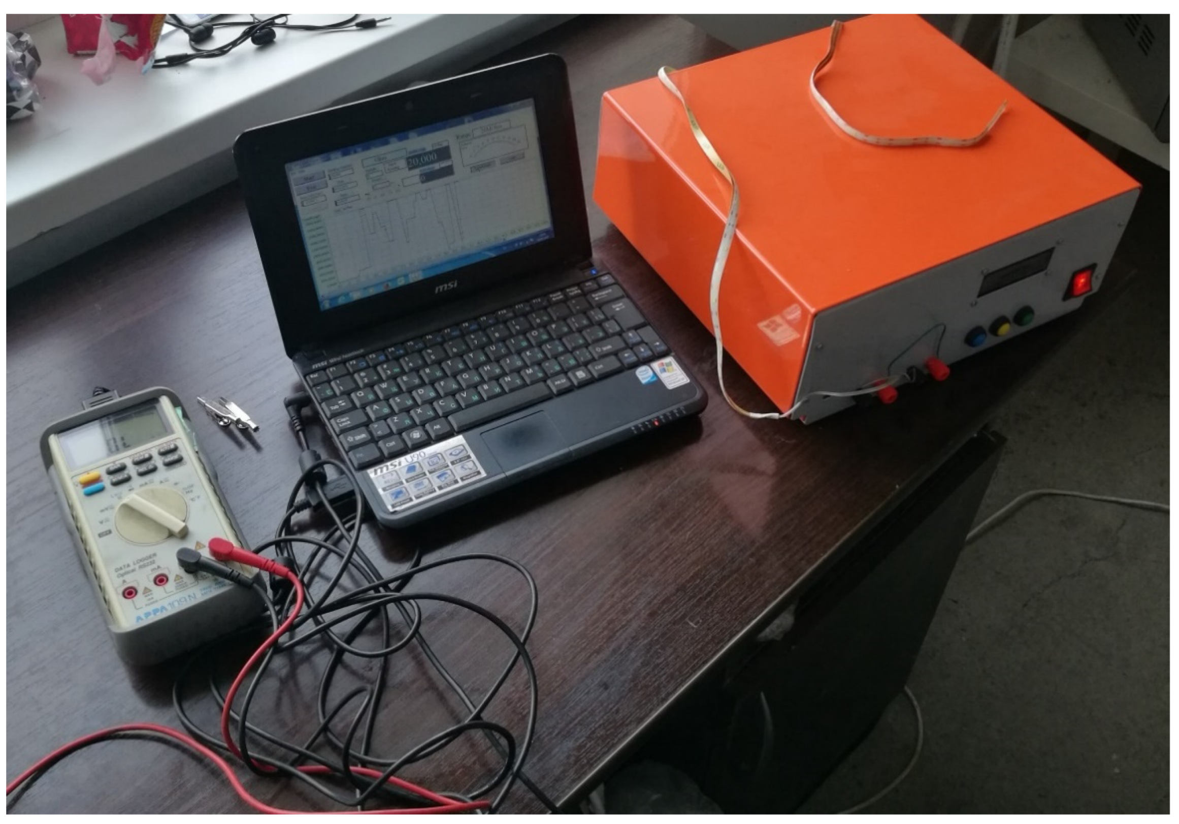
3.2. Experimental Setup

The experimental process is described in this section to assess the effectiveness and performance of the built emulator. The testing of the performance of the designed and constructed WEC emulator was achieved with the help of an APPA 109 N multimeter, as well as a laptop to record the values of the experiment, as shown in Figure 4. The output from the experimental work is presented in the results and discussions section.

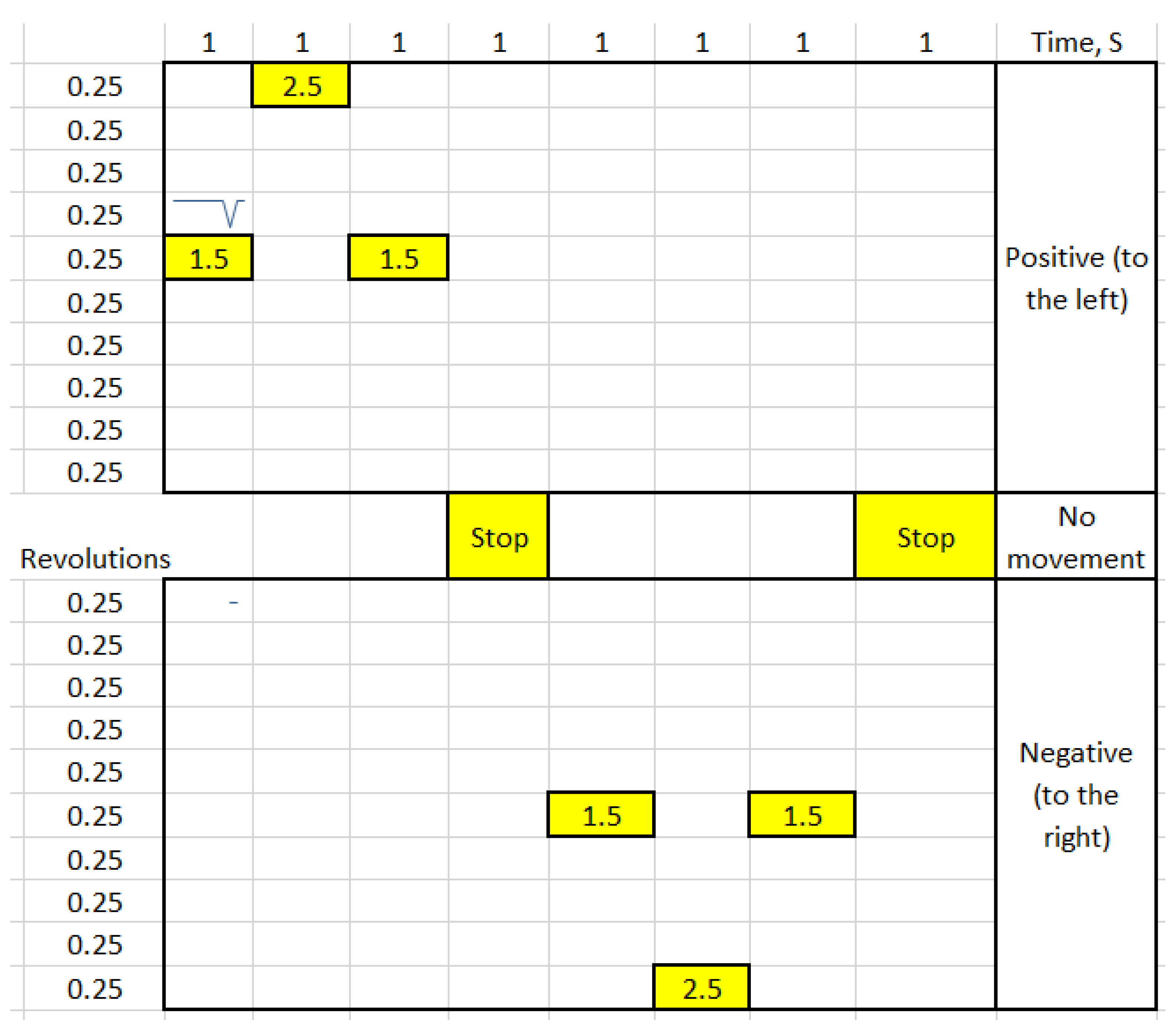
3.3. Logic of the Motor Rotation

Figure 5 shows the motor rotation logic. It was created as input for programming the master stepper motor. In the first column, the total cycle (period) is in 8 s. The loop is then closed, repeating every second equally. The cycle of seconds is divided into parts, and each part is equal to 1 s. Every 4 s in a loop is absolute 0. The cycle begins: 1 s = 1.5 revolutions per second in the left direction (positive), followed by 2 s = 2.5 revolutions made per second to the left (positive), 3 s = 1.5 revolutions per second to the left (positive), 4 s = 0 of the completed revolution (stop), 5 s = 1.5 revolutions per second in the direction to the right side (negative), 6 s = 2.5 revolutions per second towards the right side (negative), 7 s = 1.5 revolutions per second in the direction to the right (negative) and 8 s is equal to the complete turnover in 1 s (stop).

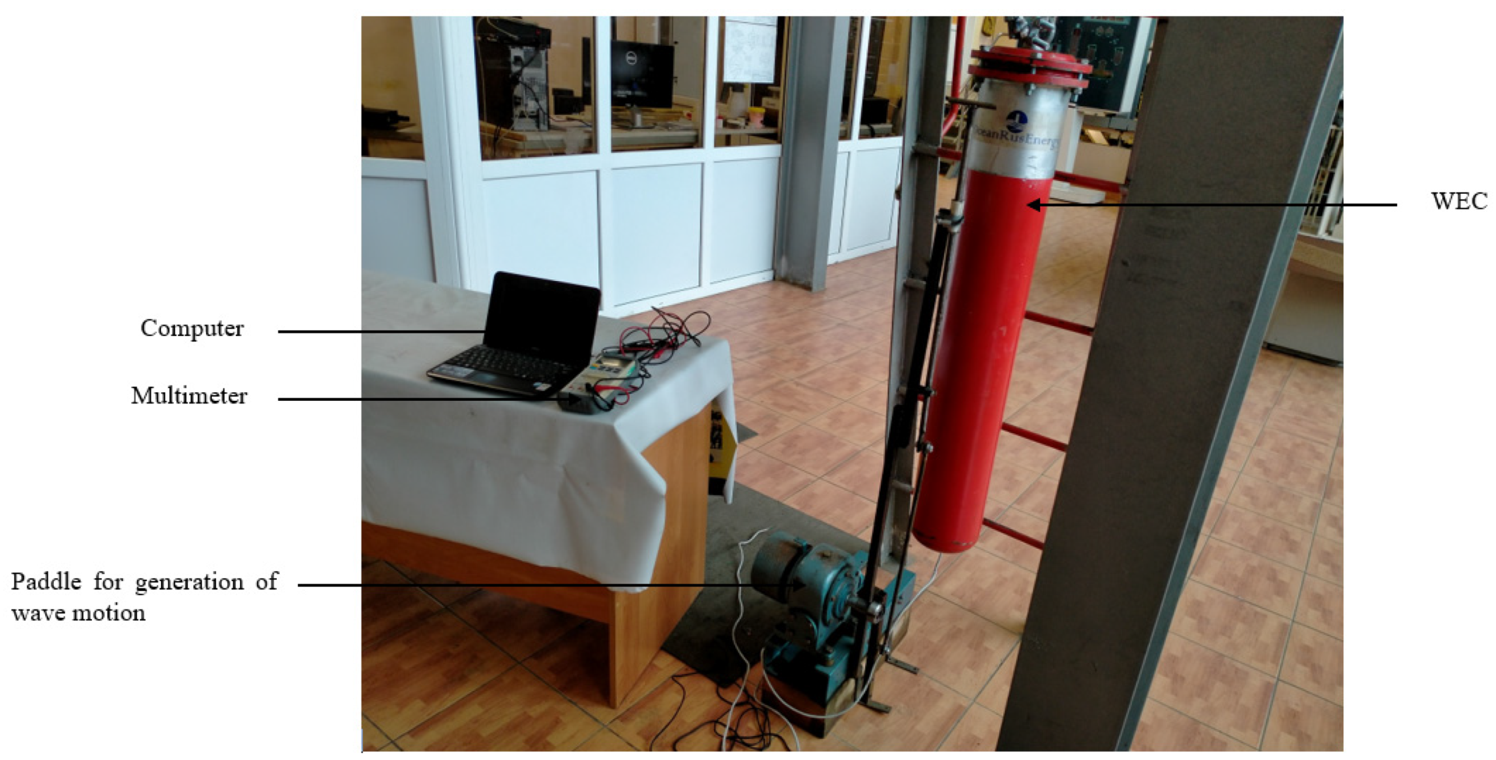
3.4. Experimental Setup for the Real Point-Absorber WEC

In order to validate the results from the newly built WEC emulator, another experiment using a point-absorber WEC constructed by one of the authors located in the Ural Federal University laboratory was performed. Wave generation for the WEC was performed using a special paddle developed by the university, which is capable of generating wave motions with a frequency ranging between 0.5 and 2 Hz. The experimental setup for the WEC is represented in Figure 6. Data were recorded with the help of the APPA software. The WEC used in this study uses the direct mechanical drive PTO system. The direct mechanical drive PTO system translates the mechanical energy of the oscillating body as a result of the movement of the waves into electricity using an extra mechanical system, which drives a rotary electrical generator. One of the advantages associated with this PTO technology is that it has high efficiency because only up to three energy conversions are necessary [21]. The experiment considered only the heave motion of the wave.

4. Results and Discussion

The results and discussion from the experiments are presented in this section. The emulator device is programmable, which makes it possible to create under laboratory conditions the operating mode of the wave generator, identical to how the wave generator would work in real sea conditions. It allows the user to set different programs, with different amplitudes, heights, periods and other initial values of sea waves as a renewable energy source. The test bench, according to a given program, will generate electrical impulses that are close to real conditions as much as possible. This allows in laboratory conditions to conduct scientific, educational, engineering and design work on the processing of electrical impulses and construction (design) of a further electronic circuit of wave generators.
In assessing the performance of WEC, one of the parameters of major concern is its average output power because the total energy production is associated with the average power rather than the maximum power. The average absorbed power over a single wave period for a sinusoidal wave is equivalent to half of the maximum power [41]. The performance of the emulator relative to its voltage output is presented in Figure 7b, which is compared to the real WEC output in Figure 7a. Figure 8a,b also indicates the power output of the emulator and WEC, respectively. The results from the two figures show a significant disparity between the WEC and the emulator. The power output for the WEC is higher than that of the emulator. This disparity is a result of the differences in the speed level of the motor. The program (code) written to operate the emulator has a slower speed with respect to the operations of the motor. As a result, the power output of the emulator is lower. This is not because the emulator cannot perform, but it is a result of the program written for the WEC emulator, and increasing the speed of the motor will positively affect its output power. The power output of the generator in the speed control mode can be employed to evaluate the power conversion circuit. Nevertheless, the generator operates as an infinite power source. Hence, in order to assess the WEC’s generation capability and also confirm the control operation of the generator, it is necessary to emulate the WEC through the torque control of the motor [26].
As indicated in Figure 8, both systems provided fluctuated power, which reflects the behavior of an incident wave. In the case of a direct-drive WEC, the fluctuations can be smoothened with the integration of an energy storage system. The appropriate technology, which seems to be the best relative to the flattening of the power of such systems, is the inclusion of supercapacitors [42], which future studies by authors are going to consider.
The results from the experimental analysis are confirmed by an earlier study with the same WEC [43], which identified that the power capacity of the unit is within the range of 20 to 60 W. According to the study, the power of a WEC can be increased when a number of WECs are combined to form a single cluster.

5. Conclusions

A WEC emulator was developed and presented in this paper. This emulator was constructed to serve as a substitute for a WEC in laboratories for the performance assessment of a WEC as if it were in a real sea environment. This is expected to help researchers in the wave energy industry to cut down the cost and time associated with the testing of WECs in a real sea environment. The main objective of designing and constructing such a system has been achieved. An experiment was conducted with a WEC emulator based on an initial program (algorithm) that was written to test its performance. The outcome was compared with experimental data from a mini point-absorber WEC designed and patented by one of the authors of this paper. The results showed that the newly built WEC emulator has a relatively small output power compared to a real WEC. This can be attributed to the speed of the motor in the program written for the emulator. Increasing the speed will increase the output power of the emulator. This means that the proposed WEC emulator is an important tool that can be used in the wave energy industry to assess the effectiveness of a designed WEC prior to construction and deployment. The emulator has been designed in such a way that any control algorithm can be executed in it.
This work is, however, the initial aspect of the development and assessment of the current project. There are other future studies that have to be conducted to test the performance of the emulator further. Such studies will include the simulation of the developed emulator in some engineering tools such as MATLAB to be able to conduct a more dynamic assessment of it. This will help to obtain more results to compare with other models. However, the main objective of building the model has been achieved. With respect to the device, the following are the future plans:
1. At the moment, work is underway to modernize the test device. A number of changes have been made to the design documentation aimed at a significant reduction in the size of the device. This set of measures should make it possible to reduce the cost of manufacturing the device during serial production.
2. It is planned to create one more additional program of the device operation algorithm.
3. The next step is to create a menu program for the device interface, which will allow the first and second programs of the operating mode code, as well as several more programs, to be simultaneously placed in the device.

6. Patents

The prototype WEC in this paper, as indicated in Figure 1, used for the experimental analysis is protected under Russian Law (Patent Number: 139434).

Author Contributions

Conceptualization, A.E.; methodology, A.E. and E.B.A.; software, A.E., E.B.A. and S.P.; validation, A.E. and E.B.A.; formal analysis, A.E. and E.B.A.; investigation, A.E. and E.B.A.; resources, A.E. and E.B.A., S.P.; data curation, A.E., E.B.A. and S.P.; writing—original draft preparation, E.B.A.; writing—review and editing, E.B.A.; visualization, E.B.A.; supervision, V.I.V.; project administration, A.E. and E.B.A. All authors have read and agreed to the published version of the manuscript.

Funding

This research received no external funding.

Institutional Review Board Statement

Not applicable.

Informed Consent Statement

Not applicable.

Data Availability Statement

The data presented in this study are available on request from the corresponding author.

Conflicts of Interest

The authors declare no conflict of interest.

References

  1. Agyekum, E.B. Energy poverty in energy rich Ghana: A SWOT analytical approach for the development of Ghana’s renewable energy. Sustain. Energy Technol. Assess. 2020, 40, 100760. [Google Scholar] [CrossRef]
  2. Agyekum, E.B. Techno-economic comparative analysis of solar photovoltaic power systems with and without storage systems in three different climatic regions, Ghana. Sustain. Energy Technol. Assess. 2021, 43, 100906. [Google Scholar] [CrossRef]
  3. Faraggiana, E.; Chapman, J.; Williams, A.; Masters, I. Genetic based optimisation of the design parameters for an array-on-device orbital motion wave energy converter. Ocean Eng. 2020, 218, 108251. [Google Scholar] [CrossRef]
  4. Agyekum, E.B.; Velkin, V.I. Optimization and techno-economic assessment of concentrated solar power (CSP) in South-Western Africa: A case study on Ghana. Sustain. Energy Technol. Assess. 2020, 40, 100763. [Google Scholar] [CrossRef]
  5. Agyekum, E.B.; Nutakor, C. Feasibility study and economic analysis of stand-alone hybrid energy system for southern Ghana. Sustain. Energy Technol. Assess. 2020, 39, 100695. [Google Scholar] [CrossRef]
  6. Agyekum, E.; Velkin, V.I.; Hossain, I. Sustainable energy: Is it nuclear or solar for African Countries? Case study on Ghana. Sustain. Energy Technol. Assess. 2020, 37. [Google Scholar] [CrossRef]
  7. Isaacs, J.D.; Castel, D.; Wick, G.L. Utilization of the energy in ocean waves. Ocean Eng. 1976, 3, 175–187. [Google Scholar] [CrossRef]
  8. Li, X.; Chen, C.; Li, Q.; Xu, L.; Liang, C.; Ngo, K.; Parker, R.G.; Zuo, L. A compact mechanical power take-off for wave energy converters: Design, analysis, and test verification. Appl. Energy 2020, 278, 115459. [Google Scholar] [CrossRef]
  9. Astariz, S.; Iglesias, G. The economics of wave energy: A review. Renew. Sustain. Energy Rev. 2015, 45, 397–408. [Google Scholar] [CrossRef]
  10. Akpınar, A.; Kömürcü, M.I. Assessment of wave energy resource of the Black Sea based on 15-year numerical hindcast data. Appl. Energy 2013, 101, 502–512. [Google Scholar] [CrossRef]
  11. Iglesias, G.; Carballo, R. Choosing the site for the first wave farm in a region: A case study in the Galician Southwest (Spain). Energy 2011, 36, 5525–5531. [Google Scholar] [CrossRef]
  12. Falnes, J. A review of wave-energy extraction. Mar. Struct. 2007, 20, 185–201. [Google Scholar] [CrossRef]
  13. Hazra, S.; Bhattacharya, S. Modeling and Emulation of a Rotating Paddle Type Wave Energy Converter. IEEE Trans. Energy Convers. 2017, 33, 594–604. [Google Scholar] [CrossRef]
  14. Hazra, S.; Shrivastav, A.S.; Gujarati, A.; Bhattacharya, S.; Hazra, S.; Gujarati, A.; Bhattacharya, S. Dynamic emulation of oscillating wave energy converter. In Proceedings of the 2014 IEEE Energy Conversion Congress and Exposition (ECCE), Pittsburgh, PA, USA, 14–18 September 2014; pp. 1860–1865. [Google Scholar]
  15. Biligiri, K.; Harpool, S.; Von Jouanne, A.; Amon, E.; Brekken, T. Grid emulator for compliance testing of Wave Energy Converters. In Proceedings of the 2014 IEEE Conference on Technologies for Sustainability (SusTech), Portland, OR, USA, 24–26 July 2014; pp. 30–34. [Google Scholar]
  16. Abanades, J.; Greaves, D.M.; Iglesias, G. Wave farm impact on the beach profile: A case study. Coast. Eng. 2014, 86, 36–44. [Google Scholar] [CrossRef]
  17. Frid, C.; Andonegi, E.; Depestele, J.; Judd, A.; Rihan, D.; Rogers, S.I.; Kenchington, E. The environmental interactions of tidal and wave energy generation devices. Environ. Impact Assess. Rev. 2012, 32, 133–139. [Google Scholar] [CrossRef]
  18. López, I.; Iglesias, G. Efficiency of OWC wave energy converters: A virtual laboratory. Appl. Ocean Res. 2014, 44, 63–70. [Google Scholar] [CrossRef]
  19. Leijon, M.; Danielsson, O.; Eriksson, M.; Thorburn, K.; Bernhoff, H.; Isberg, J.; Sundberg, J.; Ivanova, I.; Sjöstedt, E.; Ågren, O.; et al. An electrical approach to wave energy conversion. Renew. Energy 2006, 31, 1309–1319. [Google Scholar] [CrossRef]
  20. Portillo, J.; Collins, K.; Gomes, R.; Henriques, J.; Gato, L.; Howey, B.; Hann, M.; Greaves, D.; Falcão, A. Wave energy converter physical model design and testing: The case of floating oscillating-water-columns. Appl. Energy 2020, 278, 115638. [Google Scholar] [CrossRef]
  21. Têtu, A. Power Take-Off Systems for WECs. In Quantitative Monitoring of the Underwater Environment; Springer International Publishing: Cham, Switzerland, 2016; pp. 203–220. [Google Scholar] [CrossRef] [Green Version]
  22. Tongphong, W.; Kim, B.-H.; Kim, I.-C.; Lee, Y.-H. A study on the design and performance of ModuleRaft wave energy converter. Renew. Energy 2021, 163, 649–673. [Google Scholar] [CrossRef]
  23. Al Shami, E.; Wang, X.; Ji, X. A study of the effects of increasing the degrees of freedom of a point-absorber wave energy converter on its harvesting performance. Mech. Syst. Signal Process. 2019, 133. [Google Scholar] [CrossRef]
  24. Muthukumar, S.; Jayashankar, V. Micro-controller based emulation of a wave energy converter. In Proceedings of the 2011 International Conference on Emerging Trends in Electrical and Computer Technology, Nagercoil, India, 23–24 March 2011; pp. 186–189. [Google Scholar]
  25. Blanco, M.; Moreno-Torres, P.; Lafoz, M.; Beloqui, M.; Castiella, A. Development of a laboratory test bench for the emulation of wave energy converters. In Proceedings of the 2015 IEEE International Conference on Industrial Technology (ICIT), Seville, Spain, 17–19 March 2015; pp. 2487–2492. [Google Scholar]
  26. Hazra, S.; Kamat, P.; Shrivastav, A.; Bhattacharya, S. Emulation of oscillating wave energy converter for laboratory test bed. In Proceedings of the 3rd Marine Energy Technology Symposium, Washington, DC, USA, 27–29 April 2015; p. 8. [Google Scholar]
  27. Wahyudie, A.; Susilo, T.B.; Jama, M.; Mon, B.F.; Shaaref, H. Design of a double-sided permanent magnet linear generator for laboratory scale ocean wave energy converter. In Proceedings of the OCEANS 2017—Anchorage, Anchorage, AK, USA, 18–21 September 2017; pp. 1–5. [Google Scholar]
  28. Duquette, J.; O’Sullivan, D.; Ceballos, S.; Alcorn, R. Design and Construction of an Experimental Wave Energy Device Emulator Test Rig. In Proceedings of the European Wave and Tidal Energy Conference, Uppsala, Sweden, 7 September 2009. [Google Scholar]
  29. Wang, L.; Isberg, J.; Tedeschi, E. Review of control strategies for wave energy conversion systems and their validation: The wave-to-wire approach. Renew. Sustain. Energy Rev. 2018, 81, 366–379. [Google Scholar] [CrossRef]
  30. Ilyas, A.; Kashif, S.A.; Saqib, M.A.; Asad, M.M. Wave electrical energy systems: Implementation, challenges and environmental issues. Renew. Sustain. Energy Rev. 2014, 40, 260–268. [Google Scholar] [CrossRef]
  31. Steinn, G. Hydrodynamic Investigation of Wave Power Buoys; KTH Royal Institute of Technology: Stockholm, Sweden, 2013. [Google Scholar]
  32. Yuce, M.I.; Muratoglu, A. Hydrokinetic energy conversion systems: A technology status review. Renew. Sustain. Energy Rev. 2015, 43, 72–82. [Google Scholar] [CrossRef]
  33. Rourke, F.O.; Boyle, F.; Reynolds, A. Marine current energy devices: Current status and possible future applications in Ireland. Renew. Sustain. Energy Rev. 2010, 14, 1026–1036. [Google Scholar] [CrossRef] [Green Version]
  34. Faizal, M.; Ahmed, M.R.; Lee, Y.-H. A Design Outline for Floating Point Absorber Wave Energy Converters. Adv. Mech. Eng. 2014, 6. [Google Scholar] [CrossRef] [Green Version]
  35. Falnes, J.; Lillebekken, P.M. Budal’s latching-controlled-buoy type wave-power plant. In Proceedings of the 5th European Wave Energy Conference; 2003; p. 12. Available online: https://core.ac.uk/download/pdf/30849835.pdf (accessed on 18 March 2021).
  36. Backer, G.D. Hydrodynamic Design Optimization of Wave Energy Converters Consisting of Heaving Point Absorbers; Ghent University: Ghent, Belgium, 2009. [Google Scholar]
  37. Al Shami, E.; Zhang, R.; Wang, X. Point Absorber Wave Energy Harvesters: A Review of Recent Developments. Energies 2018, 12, 47. [Google Scholar] [CrossRef] [Green Version]
  38. Sjökvist, L.; Göteman, M.; Rahm, M.; Waters, R.; Svensson, O.; Strömstedt, E.; Leijon, M. Calculating buoy response for a wave energy converter—A comparison of two computational methods and experimental results. Theor. Appl. Mech. Lett. 2017, 7, 164–168. [Google Scholar] [CrossRef]
  39. Falnes, J. On non-causal impulse response functions related to propagating water waves. Appl. Ocean Res. 1995, 17, 379–389. [Google Scholar] [CrossRef]
  40. Urbikain, G.; De Lacalle, L.L.; Campa, F.; Fernández, A.; Elías, A. Stability prediction in straight turning of a flexible workpiece by collocation method. Int. J. Mach. Tools Manuf. 2012, 54-55, 73–81. [Google Scholar] [CrossRef]
  41. Hai, L.; Svensson, O.; Isberg, J.; Leijon, M. Modelling a point absorbing wave energy converter by the equivalent electric circuit theory: A feasibility study. J. Appl. Phys. 2015, 117, 164901. [Google Scholar] [CrossRef]
  42. Aubry, J.; Ben Ahmed, H.; Multon, B.; Babarit, A.; Clément, A. Wave Energy Converters. In Marine Renewable Energy Handbook; John Wiley & Sons, Inc.: Hoboken, NJ, USA, 2013; pp. 323–366. [Google Scholar]
  43. Hossain, I.; Velkin, V.I.; Shcheklein, S.E.; Eliseev, A.V. Structural Design Development of a Float Type Wave Micro Power Plant. IOP Conf. Ser. Mater. Sci. Eng. 2019, 481, 012007. [Google Scholar] [CrossRef]
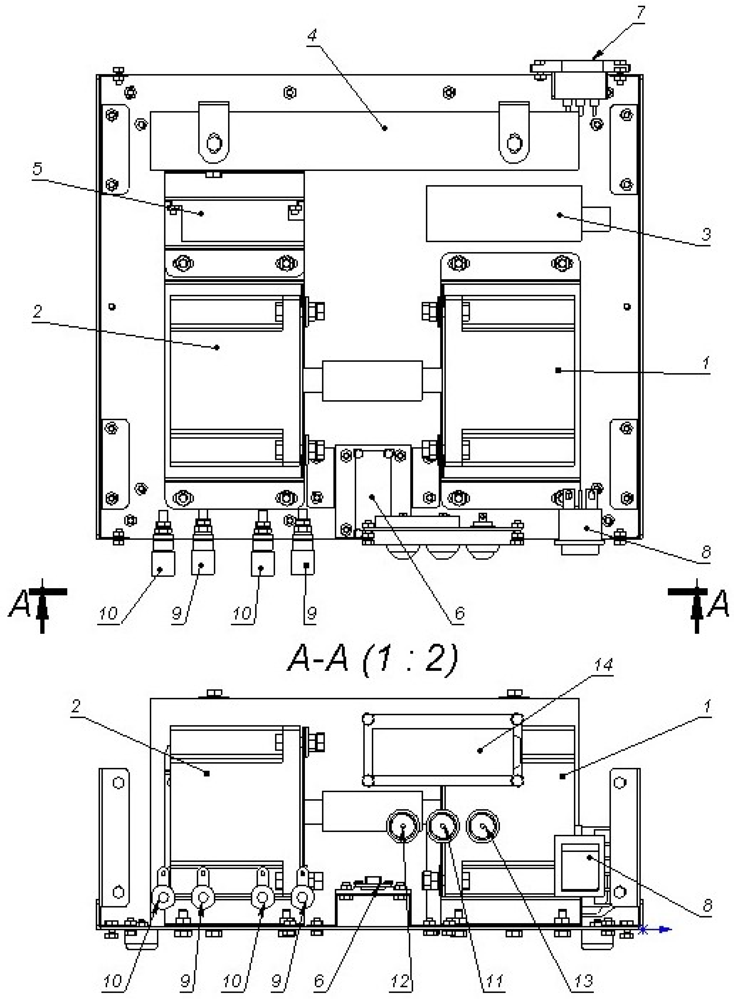
Figure 1. Schematic of a point-absorber WEC with direct mechanical PTO (designed by the authors).
Inventions 06 00020 g001
Figure 2. Schematic diagram of the WEC emulator.
Inventions 06 00020 g002
Figure 3. Proposed WEC emulator to be constructed.
Inventions 06 00020 g003
Figure 4. Experimental setup made up of a (from left to right) multimeter, laptop computer and the newly built WEC emulator.
Inventions 06 00020 g004
Figure 5. Motor rotation logic.
Inventions 06 00020 g005
Figure 6. Experimental setup for the point-absorber WEC generator.
Inventions 06 00020 g006
Figure 7. Output voltage for (a) WEC and (b) emulator.
Inventions 06 00020 g007
Figure 8. Output power for (a) emulator (b) WEC.
Inventions 06 00020 g008
Table 1. Components of the designed emulator.
NumberDesignationQuantity
1Lead stepper motor1
2Driven stepper motor1
3RS-25 power supply1
4Power supply LRS-350-481
5G210 Driver1
6Arduino Nano1
7Network socket C14 on REX ANT housing1
8Rocker switch 250 V 16 A1
9Panel socket 10-0019 red2
10Panel socket 10-0019 black2
11Switch-push button 250 V 1 A yellow1
12Switch-push button 250 V 1 A green1
13Switch-push button 250 V 1 A blue1
14Liquid-crystal display (LCD)1
Publisher’s Note: MDPI stays neutral with regard to jurisdictional claims in published maps and institutional affiliations.

