Article

A Novel Nonsingular Terminal Sliding Mode Control-Based Double Interval Type-2 Fuzzy Systems: Real-Time Implementation

by
Hooman Mohammadi Moghadam
1,
Meysam Gheisarnejad
2,*,
Maryam Yalsavar
3,
Hossein Foroozan
4 and
Mohammad-Hassan Khooban
2
1
Department of Electrical Engineering, Shiraz University of Technology, Shiraz 71557, Iran
2
Department of Electrical and Computer Engineering, Aarhus University, 8200 Aarhus, Denmark
3
Department of Electrical and Computer Engineering, Shiraz University, Shiraz 71454, Iran
4
Electrical Engineering Department, Iran University of Science and Technology, Tehran 16846, Iran
*
Author to whom correspondence should be addressed.
Submission received: 25 March 2021 / Revised: 16 May 2021 / Accepted: 19 May 2021 / Published: 4 June 2021
(This article belongs to the Special Issue Microgrids: Protection, Cyber Physical Issues, and Control)

Abstract

:
Extensive use of wind turbine (WT) systems brings remarkable challenges to the stability and safety of the power systems. Due to the difficulty and complexity of modeling such large plants, the model-independent strategies are preferred for the control of the WT plants which eliminates the need to model identification. This current work proposes a novel model-independent control methodology in the rotor side converter (RSC) part to ameliorate low voltage ride through (LVRT) ability especially for the doubly-fed induction generator (DFIG) WT. A novel model-independent nonsingular terminal sliding mode control (MINTSMC) was developed based on the principle of the ultra-local pattern. In the suggested controller, the MINTSMC scheme was designed to stabilize the RSC of the DFIG, and a sliding-mode supervisor was adopted to determine the unknown dynamics of the proposed system. An auxiliary dual input interval type 2 fuzzy logic control (DIT2-FLC) was established in a model-independent control structure to remove the estimation error of the sliding mode observer. Real-time examinations have been carried out using a Real-Time Model in Loop (RT-MiL) for validating the applicability of the proposed model-independent control in a real-time platform. To evaluate the usefulness and supremacy of the MINTSMC based DIT2-FLC, the real-time outcomes are compared with outcomes of RSC regulated conventional PI controller and MINTSMC controller.

1. Introduction

As the world is experiencing a diminishing trend in terms of fossil fuels and their bad effects on the environment through emitting harmful gases into the atmosphere, wind energy has become the fastest-growing renewable energy source that has an eco-friendly power generation [1,2,3,4,5]. For this reason and also due to the advanced technological equipment and facilities, the number of wind turbine installations along with their size has increased for converting the wind’s kinetic energy into electrical energy. Moreover, wind farms are replacing conventional power generating techniques that worked with fossil fuels as their energy resource. Therefore, the existing grid codes are not valid anymore and they should be modified to remain stable and act the same as synchronous generators during voltage dips [6,7,8]. One of the most important factors in grid codes for ensuring the stability of voltage is the low-voltage ride through (LVRT). LVRT specifies the ability of wind farms to stay in a grid-connected mode during the occurrence of a voltage sag/dip. The LVRT compares the voltage terminal with its minimum characteristics, thus if the voltage is below these characteristics the generator will trip, otherwise, the generator must remain connected and support the grid. Therefore, the functionality of the LVRT will increase the reliability of the systems during fault occurrences [9,10,11].
Voltage dips and fault occurrence present wind turbines system, especially the DFIG, with many difficulties of being connected to the power grid that overwhelms the LVRT’s ability during voltage dips because the stator flux of stator does not track abrupt alteration at its voltage, as well as the DC part in the flux of stator reveals [12,13,14]. While the electrical rotor keeps rotating and also because of the impact of speed, it is more likely that an overvoltage and overcurrent event will occur. Moreover, voltage dips can cause oscillations in the electrical currents, active power, and also reactive power of the machine. Besides, the condition is much worse for the asymmetrical faults, such that they produce a negative sequence component with a very high slip in the stator voltage and create more damages. In these situations, the rotor side converter (RSC) is commonly blocked by crowbar circuits to protect it from the overcurrent and overvoltage durations, whereby crowbar circuits do so by putting the rotor windings in short circuit and bypassing the RSC, and as a result, the connectivity of the system to the power grid and its LVRT will devastate [15]. Thus, several works have designed or improved the control algorithms of the RSC to ride it through fault occurrences instead of activating and using crowbar circuits to increase their LVRT factor. In [16], a novel fault current limiter with help of reactive power and inductance emulating control is developed to improve the LVRT factor, while other works used R-SFCL independent from the control parts. Besides, the authors of [10] designed a new reactive power control strategy by combining the rotor side, as well as grid side converter (GSC), for improving stability and LVRT factor of the system.
Sliding mode control (SMC) has been a robust method to control nonlinear models that have uncertainty in their system model and parameters, and thus, need to arrive at a high performance under external disturbances [17]. Moreover, it comprises of double steps, sliding surface and off surface dynamics, it first defines the sliding surface, and then tries to keep the state of the system near to or on that surface to satisfy the desired goals and performance [18]. Today, to improve its robustness and precision and also for confronting its drawbacks such as finite-time stability and rapid response, some methods like terminal SMC (TSM) [19], the nonsingular TSM (NTSM) [20,21], fast TSM (FTSM) [22], and nonsingular fast TSM (NFTSM) [23] have been developed. NTSM, FTSM, and NFTSM have been developed to increase time convergence and elimination of singularity problems, and TSM adds the nonlinear element in sliding variables that have been developed for limited period convergence for state variables, having a more precise and faster tracking and improving the transient performance.
The interval type 2 fuzzy logic control (IT2-FLC) is an extension of classic (Type-1) FLCs and has been a remarkable breakthrough in the field of computational intelligence [24,25,26,27,28]. Particularly, the IT2-FLCs have been developed in different areas of engineering such as robotics [29,30], networked systems [31], coaxial tri-rotor aircraft [32], load frequency control [26], and ship power systems [33]. The IT2-FLCs provide a high level of uncertainty suppression, as well as handling the non-linear dynamics than its T1-FLCs and traditional counterparts. These advantages are reached owing to an extra degree of independence prepared using the footprint of uncertainty (FOU), which is realized by their T2 fuzzy sets (T2-FSs). However, the efficiency and robustness of the IT2-FLCs depend on the FOU coefficients that impose a great challenge in its implementation in sophisticated practical systems. To solve the shortcomings related to classic IT2-FLCs, single input IT2-FLCs (SIT2-FLCs) [5,34,35,36] and double input IT2-FLCs (DIT2-FLCs) [37,38,39] have been characterized based on control surfaces. Several research works show that by adjusting only the FOU coefficients, a specific degree of robustness can be offered in a straightforward scheme.
In this paper, an innovative model-independent control methodology was developed for the regulation of RSC to boost the LVRT performance in the DFIG WT plant, without accurate knowledge of the system dynamics. The main idea is to implement a MINTSMC based DIT2-FLC controller for the DFIG system to enhance the stability of the system by appropriate control of the RSC.
The main purposes of the current article could be assessed as
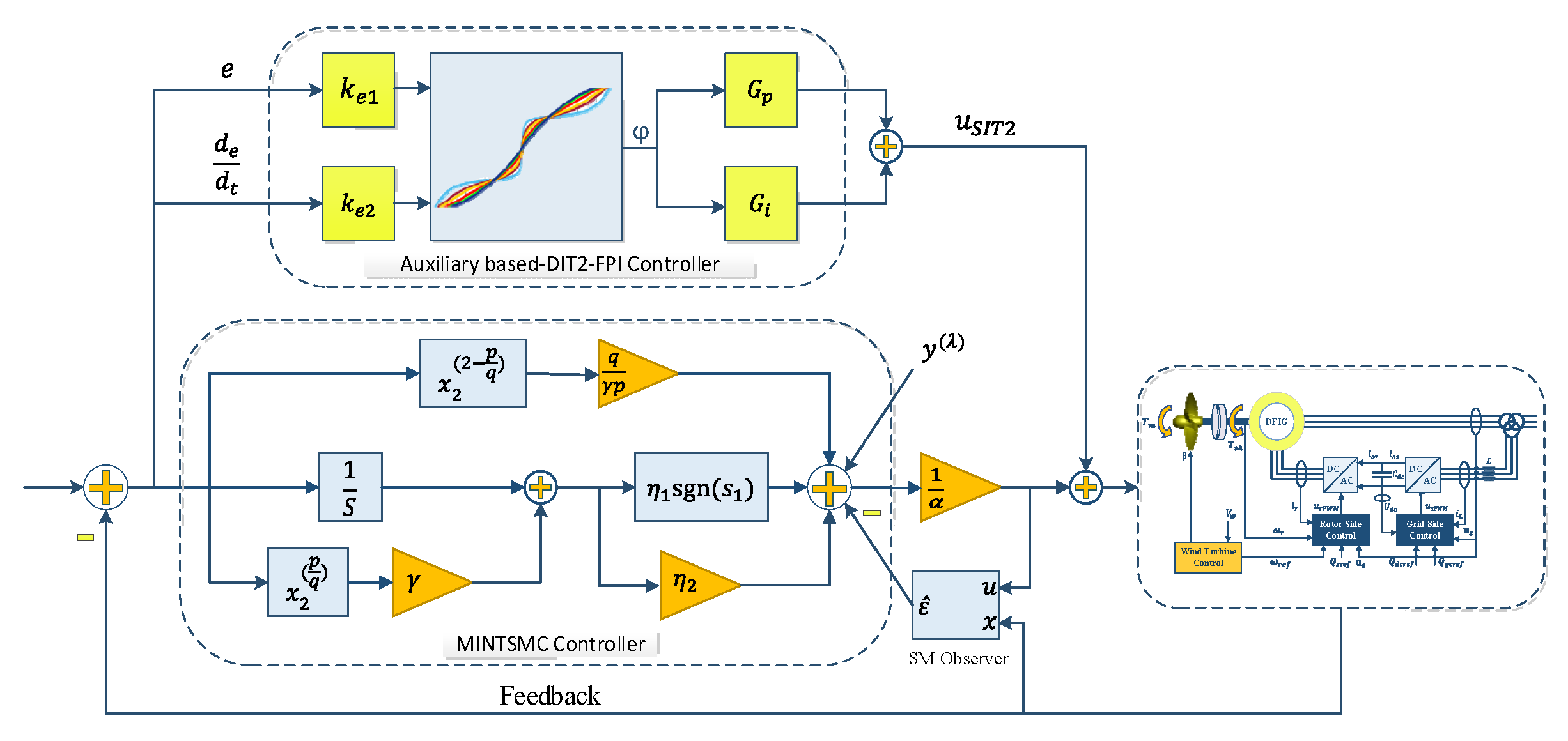
  • A MINTSMC controller with SM observer was adopted for the internal loop control of RSC in a DFIG WT test system.
  • An auxiliary DIT2-FLC controller was established to improve the DFIG performance and eliminate the SM observer estimation error.
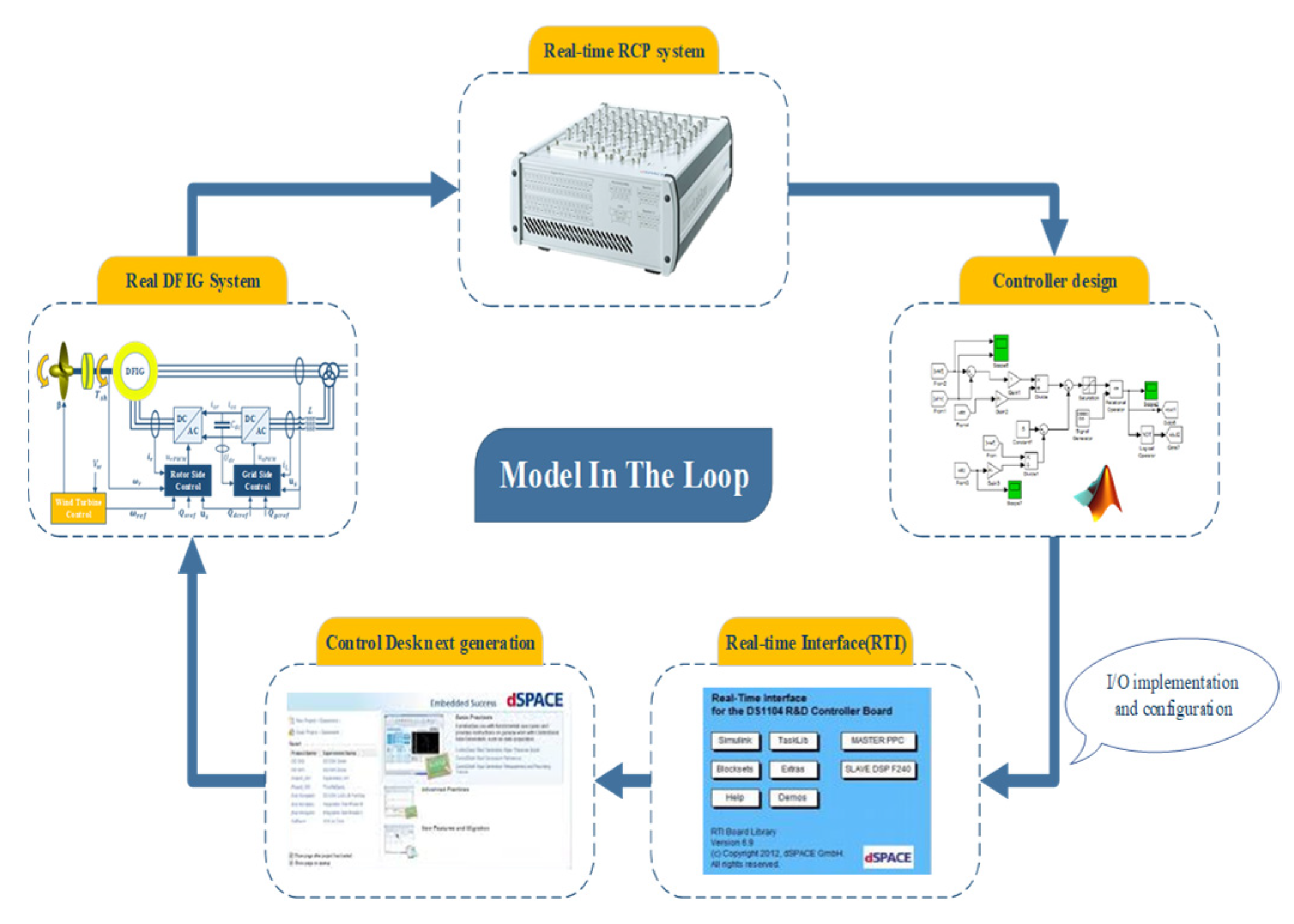
  • The comprehensive real-time model-in-the-loop (RT-MiL) examinations were made to validate the applicability of the suggested MINTSMC based DIT2-FLC controller in a real-time testbed.
This work is arranged as follows. The mathematical modeling for the DFIG WT plant is formulated in Section 2. In Section 3, the MINTSMC controller along with the auxiliary DIT2-FLC controller is provided. Section 4 describes real-time outcomes of the MiL platform to affirm the theoretical assertions. Finally, the conclusion of the current work is presented in Section 5.

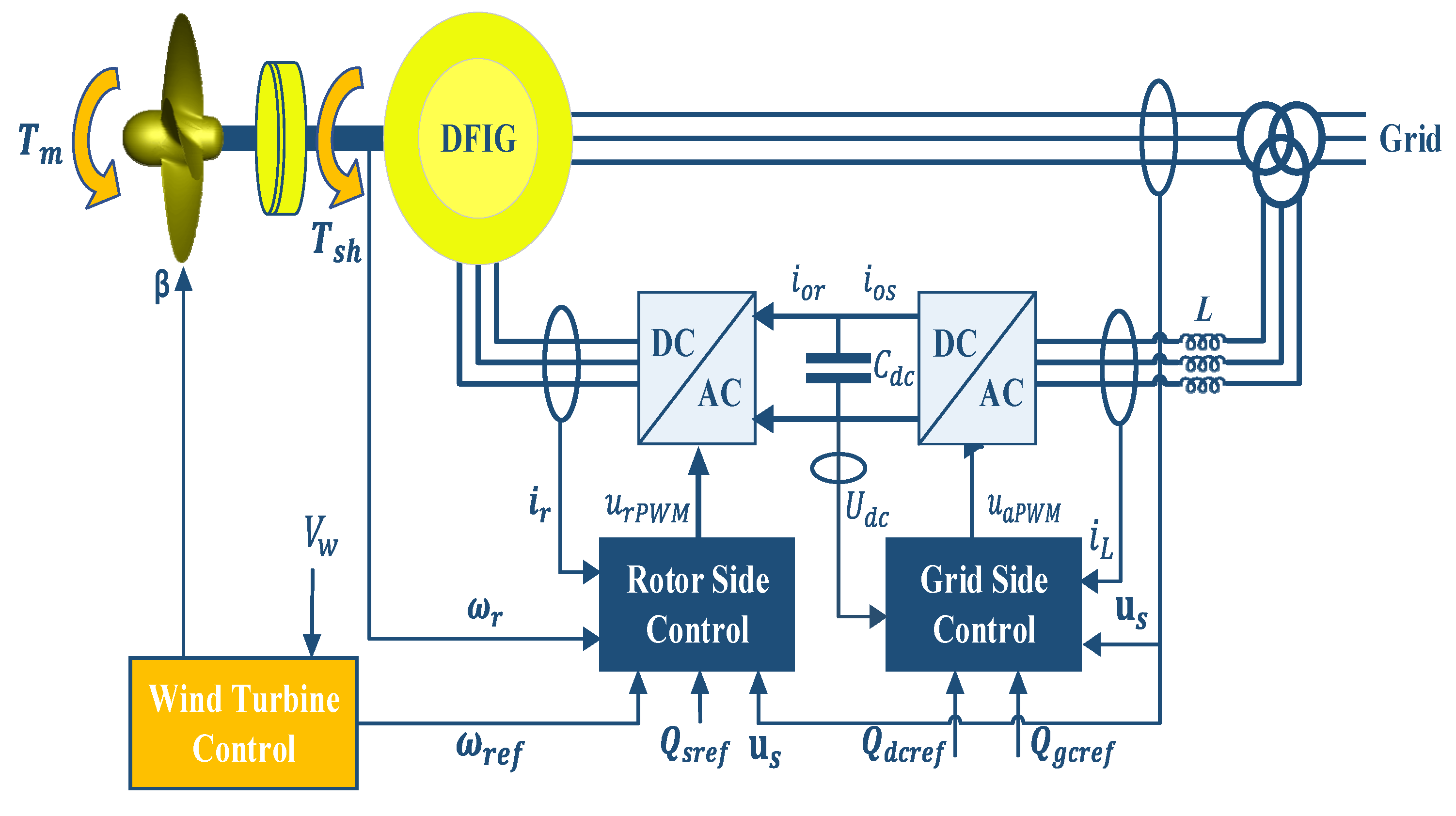
2. Modeling of DFIG WT Test-System

The DFIG WT schematic diagram is demonstrated in Figure 1, connecting to the power grid using a power transformer. The DFIG WT system includes a control system, a back-to-back PWM converters drive train, induction generator, wind turbine, and blade, while its control structure comprises two significant levels, the DFIG and WT control. First, the WT control is responsible for creating the desired magnitude of the DFIG rotor speed using calculated wind pace and an optimal power-speed feature curve that adjusts wind turbine mechanical power through the pitch angle.

2.1. Modeling of the Generator System

Using the d-q reference frame rotating at synchronous speed, the equations of stator voltage, as well as rotor circuit drove are as follows [40,41].
{ u d s = R s i d s ω s φ q s + 1 ω b d φ d s d t u q s = R s i q s ω s φ d s + 1 ω b d φ q s d t u d r = R r i d r ( ω s ω r ) φ q r + 1 ω b φ d r d t u q r = R r i q r ( ω s ω r ) φ d r + 1 ω b φ q r d t
where u d s and u q s represent the electrical stator voltage of the d and q axis of the wind turbine, respectively. u d r and u q r denote the electrical rotor voltage of the d and q axis of the wind turbine, respectively. ω s is the electrical synchronous speed of a wind turbine generator, ω r is the electrical speed of the rotor, and ω b is the base speed of the wind turbine. Likewise, R s and R r are defined as the electrical resistance of stator and rotor of the generator, respectively.   φ q s , φ d s , φ q r and φ d r are the electrical fluxes of the generator for the stator and rotor [11].

2.2. Modeling of the Drive Train System

The model of the two-mass drive train is expressed using these equations
d ω r d t = 1 2 H g ( T s h T e B ω r )
d θ t d t = ω b ( ω t ω r )
d ω t d t = 1 2 H t ( T m T s h )
where ω t defines as the speed of the wind turbine, H g and H t are respectively the generator and turbine inertia constants. B defines as generator friction component. θ t defines as the angle of shaft in terms of a radian, and input torques of the wind turbine, T e , T s h , and T m that are the electromagnetic torque, the shaft torque, and the mechanical torque, respectively, and they formulate as:
T e = L m ( i q s i d r i d s i d r )
T s h = K s h θ t + D s h ω b ( ω t ω r )
T m = 0.5 ρ π R 2 C P ( λ , β ) V w 3 ω t
where ρ , R , β ,   V w , and C P are the air density, turbine radius, angle of the pitch, wind speed, and power coefficient, in which the power coefficient formulates as
C P = 0.22 ( 116 λ i 0.4 β 5 ) e 12.5 / λ i
λ i = 1 1 ( λ + 0.08 β ) 0.035 ( β 3 + 1 )
where λ = ω t R / V w defines as blade tip speed ratio, and C p ( λ , β ) arrives at its maximum, C P m a x for optimum tip speed ratio, λ o p t .
The wind turbine power regulation shown in Figure 2 is accomplished by adjusting the generator/turbine speed along the optimal attribute curve of the power speed that correlates with the highest wind received energy [42]. The DFIG runs in variable speed mode while wind velocity exists between the lower limit and nominal value, where pitch angle β and blade tip speed ratio λ are held constant to their optimal value. If the wind velocity is greater compared to the standard value, then pitch control can regulate the overrated turbine power output and reduce the generator’s speed. It can be seen that the rotor speed of the electrical rotor relation in its controller solidifies for minimum magnitude where wind velocity is higher compared to the cut-in value. It is also smaller than the lower limit to support the generator slip at less than 0.3.

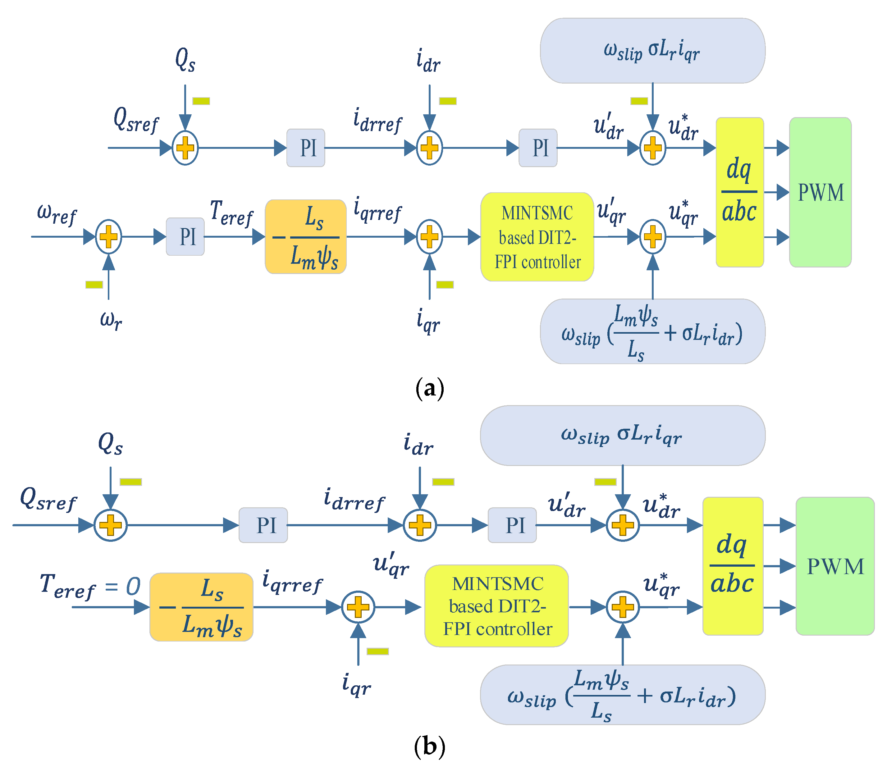
2.3. Rotor Side Converter (RSC) Control

The structure control for RSC when it is operating normally is depicted in Figure 3a. The induction generator is regulated for decoupling rotor excitation current and electromagnetic torque, using a synchronously rotating reference frame named the stator-flux oriented reference frame. Meanwhile, the d-axis component is oriented with the vector position of the stator-flux. To regulate the outer control loops mean reactive power and speed of the rotor, and inner control loops mean current of the rotor, conventional proportional integral (PI) controllers are employed [42,43]. The reference reactive power and wind turbine speed are the input variables that are compared with their actual components and then pass from PI controllers to create reference currents of the rotor in the DQ axis. In the same procedure, these variables were compared with their real components to create the reference voltages of the rotor in the DQ axis. However, for creating the uqr component, MINTSMC was employed to improve the overall performance of the system, which will be explained in detail. After that, these variables need to be decoupled for sending to PWM.
In addition, an over-current occurring in the rotor and stator circuits during short-term low voltage faults can be quenched by reducing the DFIG WT system’s imbalanced flowing energy. The presented LVRT control procedure that is shown in Figure 3b would be activated by the minimum controlled variable, containing current of rotor and stator, the voltage of DC-link and grid section, surpasses their safety value, respectively, owing to disturbances. In this technique, for transforming the received energy from the wind into kinetic energy in WT inertia, the rotor side controller can enhance the speed of the rotor by reducing generator torque around zero within disturbance. After fault clearing, the elevated kinetic energy is converted to the WT system.

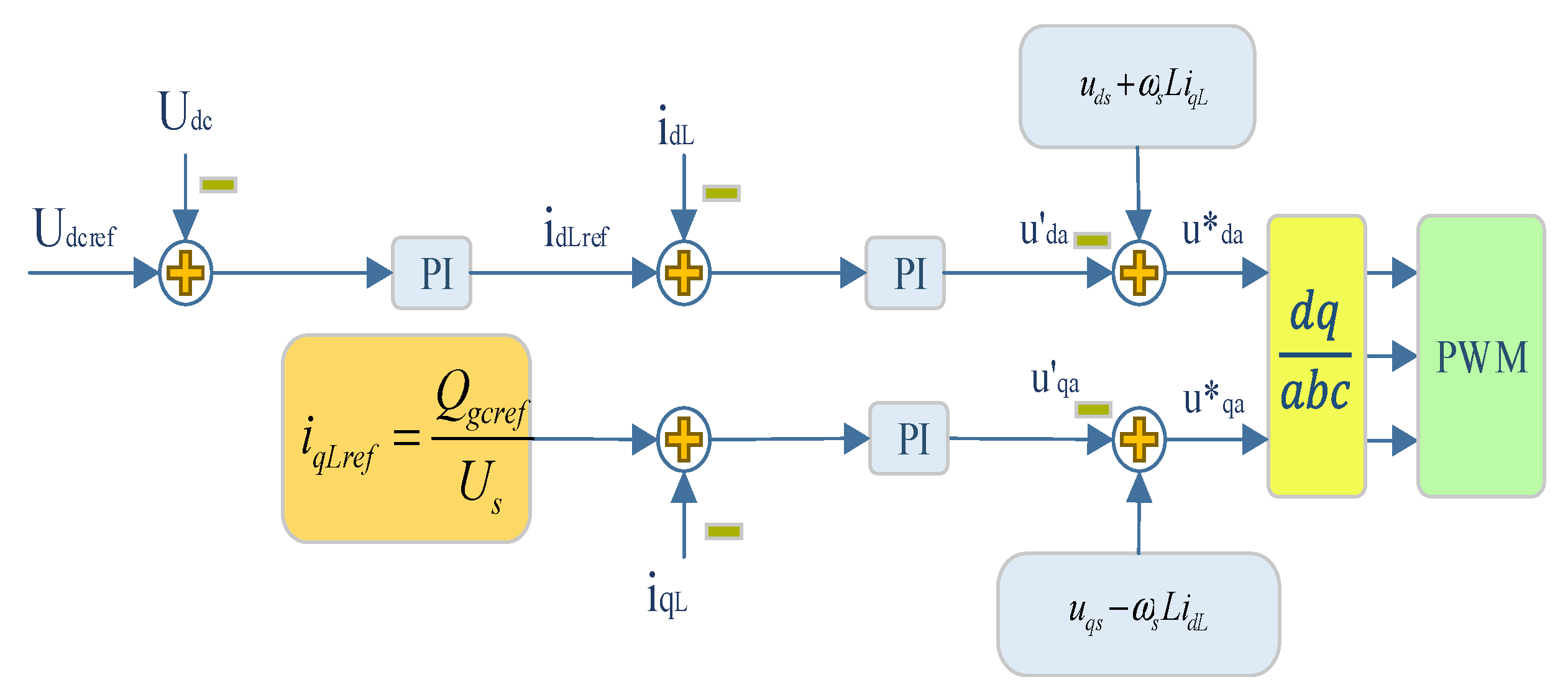
2.4. Grid Side Converter (GSC) Control

The control structure of the GSC in DFIG operation mode is shown in Figure 4, where ua and iL are the DC link voltage and inductor current vector of the GSC. Besides, the control procedure works in a grid voltage reference frame that is an asynchronously rotating reference frame with its axis centered towards vector control of grid voltage. Thereby it acquires autonomous control of the active power, as well as reactive power parameters, between the power grid and GSC.

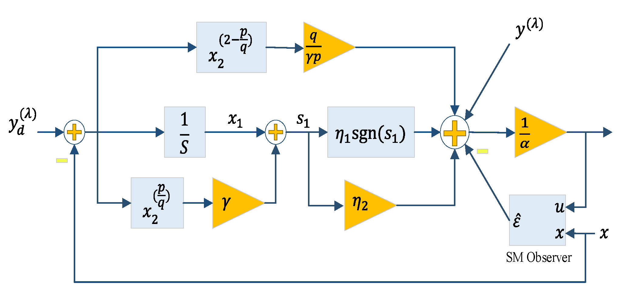
3. Design of Model-Independent NTSMC Based DIT2-FLC

3.1. Model-Independent NTSMC Technique

Definition 1.
The nonlinear system dynamics that includes un-model dynamics and disturbances, by considering the model-independent control techniques [44,45] and the approximate ULM form can be expressed as
y ( λ ) ( t ) = ε + α u v ( t )
where y ( t ) is the output, v is the derivative order, ε includes un-model dynamics along with disturbances, that is estimated based on the input signal u ( t ) and output y ( t ) , α   ϵ   is an assumed constant.
Definition 2.
New state variables,   x 1 and x 2 are introduced for determination of the sliding surface as:
{ x 1 = 0 t e 1 ( t ) d t x 2 = e 1 ( t )
Then, the state-space equations derive as Equation (10) based on Equation (11):
{ x ˙ 1 = x 2 x ˙ 2 = x ˙ α u v ε
Using the SMC framework, and proposed definitions, a second-order NTSM is presented in Equation (13) with the designed parameter γ , and the p and q are odd defined as 1 < p / q < 2 .
s 1 = x 1 + γ x 2 p / q
Which taking the derivative of Equation (13) results in
s ˙ 1 = x ˙ 1 + γ p q x 2 p q 1 x ˙ 2 = x 2 + γ p q x 2 p / q 1 ( x ˙ α u v ε )
Theorem 1
[46]. The error in the specified state-space (12) converges to zero in finite time, e 0 , if the NTSMC manifold is considered as (13) and control law is formulated as follows
u v = 1 α [ ε ^ + x ˙ + 1 γ q p x 2 2 p / q + η 1 s g n ( s 1 ) + η 2 s 1 ]
where, ε ^ is the estimated value for ε , η 1 and η 2 are the designed parameters, and η 1 > ε ^ ε + μ ( μ > 0 ) .
Proof. 
By considering the Lyapunov function as:
V 1 = 1 2 s 1 T s 1
And substituting (14) into its derivative, one can obtain:
V ˙ 1 = s 1 T s ˙ 1 = s 1 T γ p q x 2 p / q 1 ( ε ^ ε η 1 s g n ( s 1 ) η 2 s 1 ) = s 1 T γ p q x 2 p / q 1 ( ε ˜ η 1 s g n ( s 1 ) η 2 s 1 ) γ p q x 2 p / q 1 ( ( ε ˜ η 1 ) s 1 η 2 s 1 2 )
where the estimation error F ˜ = F ^ F is bounded because
1 < p / q < 2 ,   0 < p / q 1 < 1
And exists x 2 p / q 1 > 0 for p and q are odd constants. when η 1 > ε + μ ( μ > 0 ) , the Equation (18) will be converted into:
V ˙ 1 γ p q x 2 p / q 1 ( μ s 1 η 2 s 1 2 ) 0
Thus, the stability of the controller will be satisfied by the demand of the Lyapunov theory. □

3.2. Design of SM Observer

For dealing with un-model dynamics, input disturbances, and due to the superior characteristics of sliding-mode (SM) observers, for example, their simplicity, flexibility, and robust control framework, an observer-based SM was adopted in this work. The overall control structure of NTSMC along with the SM observer can be seen in Figure 5. Using the SM observer, the unknown parts of the block converter, Φ , which can be seen in Equation (8) are estimated as Φ ^ using the following ultra-local model formulation [46]:
x ^ ˙ = σ s g n ( x x ^ ) + Λ u
where x ^ denotes the observed value of x ; σ s g n ( x x ^ ) represents the term relating to sliding control, also σ is defined as the designed coefficient and s g n ( ) symbolizes a sign function.
Then, by considering the sliding surface of SM as e 2 = x x ^ and subtracting Equation (10) from Equation (20), the error dynamic derives as
e ˙ 2 = Φ σ s g n ( x x ^ )
Theorem 2
[46].For (13), choosing the SM manifold as s = e and σ appropriately results in the asymptotical convergence of the error to zero.
Proof. 
If the Lyapunov function be chosen as
V = 1 2 s 2
By differentiating Equation (22) concerning time, the following inequality derives
V = s s ˙ = e 2 e ˙ 2 = e 2 ( Φ σ s g n ( e 2 ) ) e 2 ( Φ σ )
Now, supposing that σ satisfies the condition of Φ + η < σ , where η > 0 , according to Equation (16), one can obtain
V ˙ η e 2
This implies the asymptotical stability of the observer. □

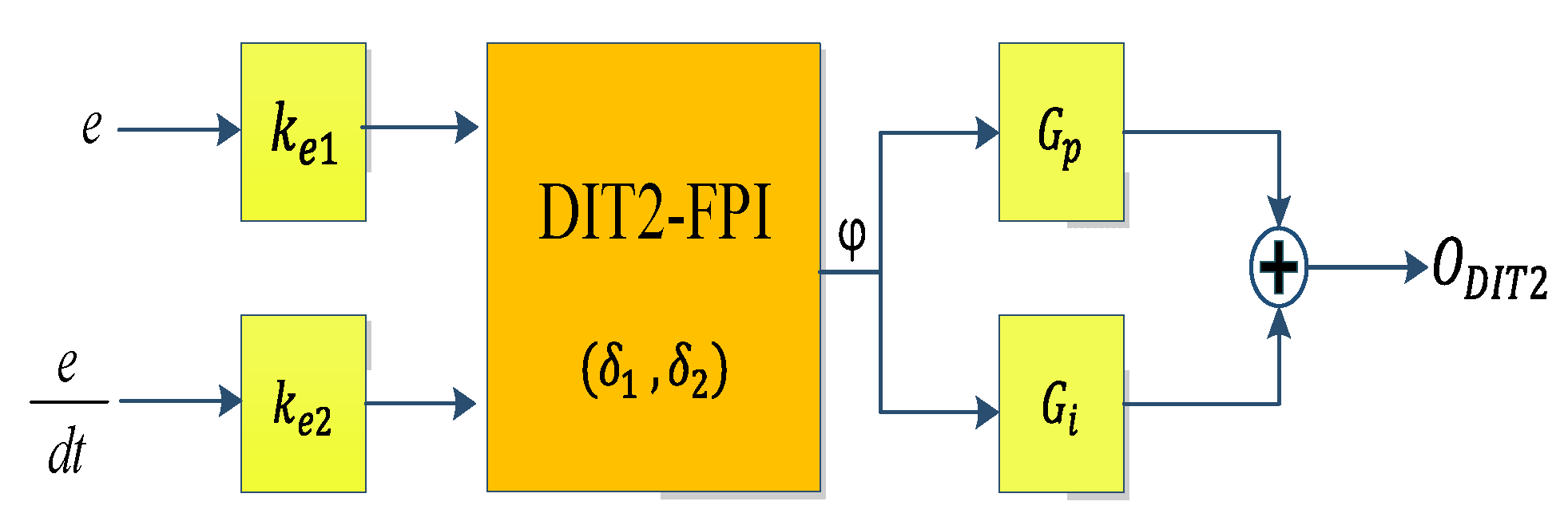
3.3. Dual Input Interval Type 2 FLC

3.3.1. General Structure of Dual Input IT2-FL

In Figure 6, the overall diagram of the PI type DIT2-FPI based on the RSC control of the DFIG WT is demonstrated. First, e and de / dt are normalized for the discourse universe of membership functions (MFs), i.e., [ 1 , + 1 ] by embedding the scaling factors (SFs) G p and G i in the structured controller. Then, they are altered to λ 1 and λ 2 , respectively, and also control the output parameter O DIIT 2 is created based on the IT2 controller output ( φ o ).
O DIT 2 = G p φ o + G i φ o d t
In which the G p and G i parameters are factors of the baseline PI structure.

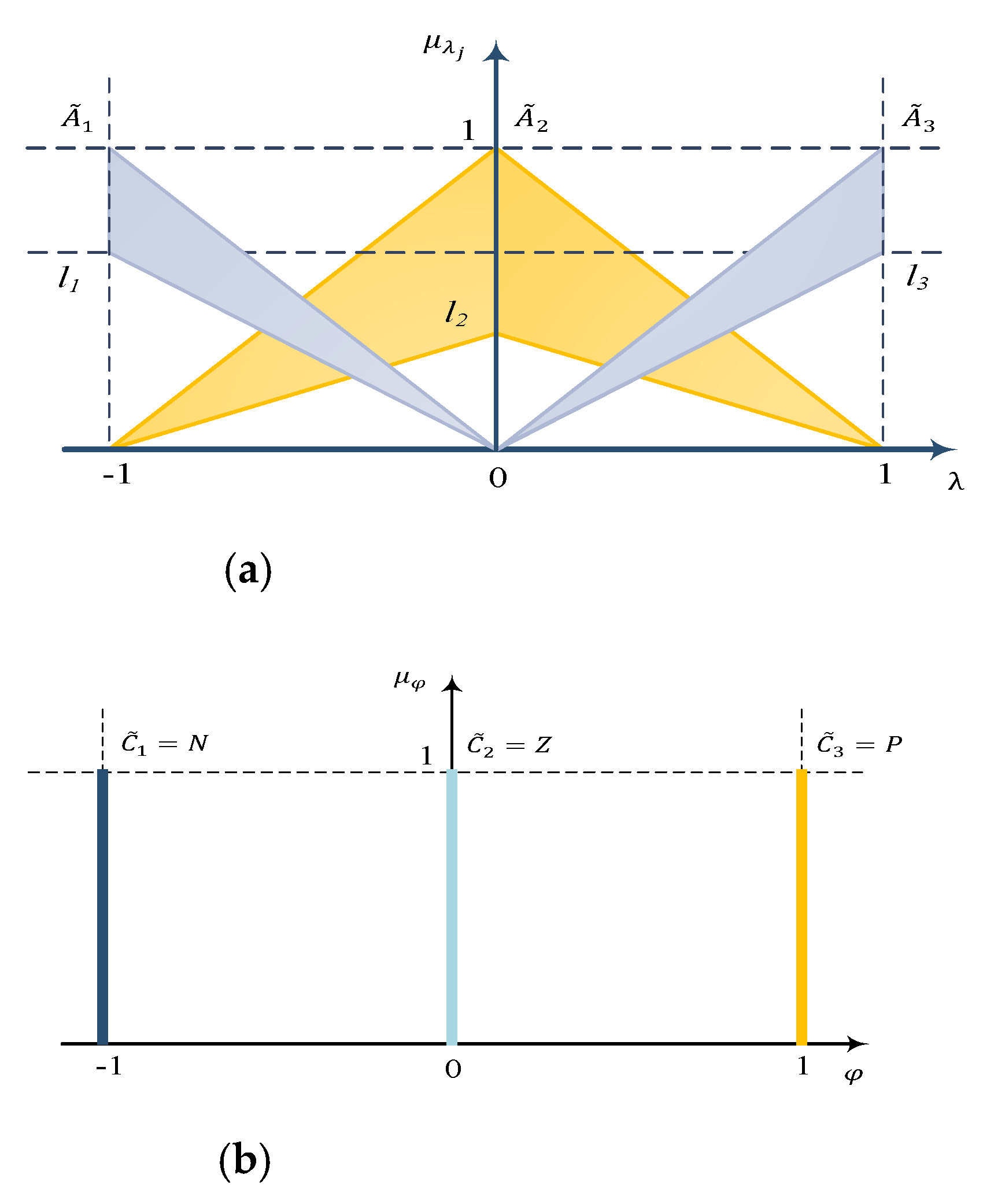
3.3.2. DIT2-FL Design Strategy

This section presents the footprint on uncertainty (FOU) and the mathematical concepts of IT2-FL [35,47], which have a similar structure to its type-1 (T1) counterpart. A significant distinction somehow defines which fuzzy sets of rule-based models are based on the IT2 fuzzy set (IT2-FS). As a result, their constituent information assesses for distinguishing the contrasts between two T1-FS and IT2-FS, while the type 2 fuzzy set, referred as A ˜ , is explained as:
A ˜ = { ( λ   , u , 1 )   |     λ   ϵ   Λ ,     u   ϵ   U λ [ 0 ,   1 ] }
Then, the unification of every primary MF (FOU) is demonstrated as:
F O U   ( A ˜ ) =   λ   ϵ   Λ U λ  
FOU is distinguished in IT2-FLs, by duo type-1 MFs, while μ ¯ A ˜ ( λ ) and μ _ A ˜ ( λ ) represents its upper and lower bounds   λ   ϵ   Λ , respectively, as follows
μ ¯ A ˜ ( λ ) = F O U   ( A ˜ ) ¯                 λ   ϵ   Λ
μ _ A ˜ ( λ ) = F O U   ( A ˜ ) _               λ   ϵ   Λ
Normally, the structural rule of DIT2-FL by considering the N rule is defined as:
R n : if   λ 1   is   A ˜ 1 , n   and   λ 2   is   A ˜ 2 , n ,   THEN   φ o   is     C n        
where the overall firing for the n th rule F n ( λ ) = [ f _ n ( λ ) ,     f ¯ n ( λ ) ] is:
{ f _ n ( λ ) = μ _ A ˜ 1 , i ( λ 1 ) μ ¯ A ˜ 2 , i ( λ 2 )   f ¯ n ( λ ) = μ ¯ A ˜ 1 , i ( λ 1 ) μ _ A ˜ 1 , i ( λ 2 )
Based on the rules of Equation (32), a DIT2-FL takes the crisp inputs λ = [ λ 1     λ 2 ] T , and returns their corresponding crisp output value, φ o . In this work, for simplification of the analytical derivation and reducing the complexity of the controller design, MFs were characterized using the IT2-FSs triangular as depicted in Figure 7a [37]. The symmetrical MFs are adopted as illustrated in Figure 7b, respectively. As a result, m j is defined as:
m j , 1 = m j , 2 = m j , 3 = δ j
Therefore, δ j consists of a design parameter that should be regulated for all inputs, λ j .
Using centroid defuzzification for type reduction of the IT2-FLC results in the defuzzified crisp output as:
φ I T 2 ( λ ) = ( φ r I T 2 + φ l I T 2 ) / 2
In which φ r I T 2 and φ l I T 2 signify endpoints of the type of reduced set which is demonstrated in Reference [36], and using iterative algorithms is common for obtaining the switching points (L, R) in these equations.
{ φ l I T 2 = n = 1 L f ¯ n ( λ )   C n + n = L + 1 N f _ n ( λ )   C n   n = 1 L f ¯ n ( λ ) + n = L + 1 N f _ n ( λ )   φ r I T 2 = n = 1 R f ¯ n ( λ )   C n + n = R + 1 N f _ n ( λ )   C n   n = 1 R f ¯ n ( λ ) + n = R + 1 N f _ n ( λ )  
Table 1 shows all of the consequent MFs that can comprehend by a parameterized function λ according to three rules named negative (N), big (B), and zero (Z). Thus, triple region modes can construct, i.e., { L = 3 , R = 3 }c, { L = 3 , R = 6 } and { L = 6 , R = 6 }, in which a region ( Γ 1 , Γ 2 , Γ 3 ) is explained at the [ λ 1   λ 2 ] plane for each mode, deploying the two separator counters β 12 and β 23 , as provided in Table 2. Moreover, β 12 and β 23 split Γ 1 from Γ 2 and Γ 2 from Γ 3 , respectively. The areas of Γ 1 , Γ 2 and Γ 3 are devoted to fuzzy mapping (FM), φ 1 I T 2 ( λ ) , φ 2 I T 2 ( λ ) and φ 3 I T 2 ( λ ) , similarly. Based on Equation (22), φ I T 2 ( λ ) is separated as [39]:
φ I T 2 ( λ ) = { φ 1 I T 2 ( λ ) = ( φ L = 3 I T 2 ( λ ) + φ R = 3 I T 2 ( λ ) ) / 2 ,             λ Γ 1 φ 2 I T 2 ( λ ) = ( φ L = 3 I T 2 ( λ ) + φ R = 6 I T 2 ( λ ) ) / 2 ,             λ Γ 2 φ 3 I T 2 ( λ ) = ( φ L = 6 I T 2 ( λ ) + φ R = 6 I T 2 ( λ ) ) / 2 ,             λ Γ 3
Using Equation (34), the left and right of endpoints of FM φ I T 2 ( λ ) are obtained as:
φ L = 3 I T 2 ( λ ) = λ 1 ( λ 2 + 1 ) λ 1 λ 2 + λ 2 ( λ 1 + 1 ) δ 1 δ 2 ( λ 1 + 1 ) ( λ 2 + 1 ) λ 1 λ 2 ( λ 1 + 1 )
φ L = 6 I T 2 ( λ ) = δ 1 δ 2 λ 2 δ 1 δ 2 λ 1 + ( λ 2 1 ) ( λ 1 1 ) ( λ 2 1 ) + δ 1 δ 2 ( δ 1 + δ 2 δ 2 δ 1 )
φ R = 3 I T 2 ( λ ) = δ 1 δ 2 λ 1 + δ 1 δ 2 λ 2 ( λ 1 + 1 ) ( λ 1 + 1 ) ( λ 2 + 1 ) δ 1 δ 2 ( λ 1 λ 2 + λ 1 + λ 2 )
φ R = 3 I T 2 ( λ ) = λ 1 ( 1 λ 2 ) + λ 1 λ 2 λ 2 ( 1 λ 1 ) δ 1 δ 2 ( λ 1 1 ) ( λ 2 1 ) λ 1 λ 2 ( λ 1 1 )
Considering the above equations, φ 1 I T 2 ( λ ) , φ 2 I T 2 ( λ ) and φ 3 I T 2 ( λ ) could be achieved from Equation (35).
By determining the divider counters:
β 12 = { λ [ 1 ,   1 ] 2   | φ R = 3 I T 2 ( λ ) = φ R = 6 I T 2 ( λ ) }
β 23 = { λ [ 1 ,   1 ] 2   | φ L = 3 I T 2 ( λ ) = φ L = 6 I T 2 ( λ ) }
β 12 and β 23 can be calculated by:
β 12 ( λ ) = { δ 1 δ 2 λ 1 λ 1 δ 1 δ 2 λ 1 + 1 ,                             λ 1 < 0   λ 1 λ 1 + δ 1 δ 2 δ 1 δ 2 λ 1 ,               λ 1 0
and
β 23 ( λ ) = { λ 1 δ 1 δ 2 λ 1 + δ 1 δ 2 λ 1 ,                             λ 1 < 0   δ 1 δ 2 λ 1 δ 1 δ 2 λ 1 λ 1 + 1 ,                                       λ 1 0

3.4. The Strategy of MINTSMC Based DIT2-FPI Scheme

To ameliorate the LVRT ability of the DFIG WT system, a novel MITSMC based DI2-FLC controller was developed for the rotor side converter. For stabilization of system outcomes of the DFIG WT system, the performance of the traditional methodologies was restricted in the following aspects:
( i ) The PI type of controllers can stabilize the system responses in the normal condition while they are ineffective when the system is subjected to uncertainties and faults.
( ii ) The model-based strategies (e.g., MPC and backstepping scheme) need accurate mathematical modeling of the system to restricts their applicability in the complex DFIG systems.
In this application, rather than relying on accurate controlled plant dynamics knowledge, the MITSMC scheme based on the ULM control scheme was proposed. In the control structure, an SM supervisor is created to assess system uncertainties and eliminate their effects on the feedback controller. Moreover, an auxiliary controller-based DIT2-FLC was established to reduce the error of the SM observers and improve system efficiency. According to the said descriptions, the overall structure of the MITSMC based DI2-FLC controller is illustrated in Figure 8. Thus, the final law control of the suggested model-independent controller is defined as:
u v = 1 α [ ε ^ + x ˙ + 1 γ q p x 2 2 p q + η 1 s g n ( s 1 ) + η 2 s 1 ] + O DIT 2 = 1 α [ ε ^ + x ˙ + 1 γ q p x 2 2 p q + η 1 s g n ( s 1 ) + η 2 s 1 ] + G p φ o + G i φ o d t

4. Results and Discussion

In this section, the DFIG WT test system developed in Section II (Figure 1) was considered to evaluate the applicability of the suggested model-independent controller. For this purpose, the MITSMC based DI2-FLC was established for the internal loop of the RSC while the external loop of RSC, as well as the internal/external loops of GSC, were controlled by a conventional PI controller. The relevant variables for the DFIG test system, established on available data about the literature and industries, are provided in Table 3. To evaluate the efficiency of the suggested MITSMC based DI2-FLC controller, the internal loop control of RSC was also designed by the PI controller and the MITSMC controller.
To confirm the applicability of the MITSMC based DI2-FLC from a real-time perspective, for the real-time analysis shown in Figure 9, a model in the loop (MiL) testbed with a dSPACE 1202 board is adopted. The AO was adopted in the Simulink environment and in a real-time platform. The solver for this platform was realized based on Runge Kutta’s procedure where the frequency sample time was 10 kHz.
Scenario I:
The wind speed was 15 m/s and the drop voltage occurred in the power grid where its amplitude was half of the grid voltage. The DC-link capacitor voltage and magnitude rotor current of the DFIG system are compared with the PI controller, MINTSMC controller, MINTSMC controller-based DIT2-FLC in Figure 10 and Figure 11, respectively. From Figure 10 and Figure 11, it is revealed that with the application of MINTSMC controller-based DIT2-FLC, the smallest overshoot amplitude, faster-settled behavior, and better dynamical outcomes are achieved compared to the others. Moreover, for ease of analyzing the performance and functionality of the proposed method, the grid voltage and current, along with active/reactive power and generator speed of the DFIG system are presented, as depicted in Figure 12, Figure 13 and Figure 14 to confirm the stabilization ability of the suggested designed RSC controller. It can be seen from the output results that active power and reactive power reached almost 0.9 MW, 0.1 MVar, after passing the transient state, respectively. Moreover, the generator speed oscillates around 1.2 p.u.
Scenario II:
In this scenario, the wind speed was 15 m/s and drop voltage occurred in the power grid where its amplitude was 20% of the grid voltage. Figure 15 and Figure 16 illustrate, respectively, the DC link capacitor voltage, and magnitude rotor current of the DFIG plant for the RSC designed by the conventional PI controller, MINTSMC controller, and MINTSMC controller-based DIT2-FLC. Output results vividly reveal that, based on the recommended RSC controller, the transient behavior for capacitor DC link voltage is ameliorated compared to other methods. It is evident that with the application of the PI controller and MINTSMC, the WT system experienced an overshoot of 1205 V and 1180 V for the voltage of the DC link capacitor, respectively. However, a lower voltage deviation of the DC link capacitor was reached by employing the suggested scheme with the overshoot of 1164 V. Figure 17 and Figure 18 demonstrate grid voltage and current correspondingly. Moreover, Figure 19 depicts the active power, reactive power, and generator speed of the DFIG plant respectively. It can be extracted that the active power parameter was reached at approximately 0.9 MW, meanwhile, the final magnitude of reactive power parameter was achieved about 0.1 MVar.
Scenario III:
In this case, the wind speed was 11m/s and the drop voltage happened in the power grid where its amplitude was half of the grid voltage. The DC-link capacitor voltage and magnitude rotor current under this scenario for the various RSC controllers are depicted in Figure 20 and Figure 21, respectively. From the outcomes of Figure 20 and Figure 21, it is revealed that superior control behavior regarding overshoot/undershoot and settling time is obtained by the suggested RSC controller, similar to previous scenarios. Figure 22 and Figure 23, demonstrate the grid voltage and current correspondingly. Moreover, the active and reactive power and generator speed of the DFIG plant is depicted in Figure 24. It can be extracted in which the active power parameter is reached at about 0.75 MW. Meanwhile, the final value of reactive power is achieved at approximately 0.1 MVar.

5. Conclusions

This paper develops the novel MINTSMC based DIT2-FPI controller to boost the LVRT ability of the DFIG WT plant in a model-independent framework. In particular, the MINTSMC controller with an SM observer is adopted for the internal control of RSC while an axillary controller-based DIT2-FPI controller is established to remove the estimation error of the SM observer. The real-time simulation is made based on the MiL platform to assess the efficiency of the proposed mode-independent design in a systematic scheme. The comparative analysis is provided to confirm the better behavior of the proposed controller than modern approaches like the PI controller and MINTSMC controller. The MiL results of the DFIG WT system demonstrated that with the application of the suggested MINTSMC based DIT2-FPI controller, the system outcomes, including grid voltage and grid current, can be effectively stabilized. In addition, a lower level of fluctuations in the terms of capacitor DC-link voltage, as well as magnitude rotor current, could be reached by the MINTSMC based DIT2-FPI controller in comparison with other considered RSC controllers. As future work, the impact of inertia on the performance of the WT system can be investigated. Since the lower system inertia will lead to larger and quicker fluctuations in the system responses, the impact of inertia should be considered in the control stage to ensure system stability.

Author Contributions

Data curation, H.M.M.; Methodology, M.G.; Software, H.F.; Supervision, M.-H.K.; Validation, M.Y. All authors have read and agreed to the published version of the manuscript.

Funding

This research received no external funding.

Institutional Review Board Statement

Not applicable.

Informed Consent Statement

Not applicable.

Data Availability Statement

Not applicable.

Conflicts of Interest

The authors declare no conflict of interest.

References

  1. Hu, J.; Nian, H.; Xu, H.; He, Y. Dynamic modeling and improved control of DFIG under distorted grid voltage conditions. IEEE Trans. Energy Convers. 2010, 26, 163–175. [Google Scholar] [CrossRef]
  2. Moghadam, H.M.; Gheisarnejad, M.; Esfahani, Z.; Khooban, M.-H. A Novel Supervised Control Strategy for Interconnected DFIG-Based Wind Turbine Systems: MiL Validations. IEEE Trans. Emerg. Top. Comput. Intell. 2020. [Google Scholar] [CrossRef]
  3. Abrazeh, S.; Parvaresh, A.; Mohseni, S.-R.; Zeitouni, M.J.; Gheisarnejad, M.; Khooban, M.H. Nonsingular Terminal Sliding Mode Control With Ultra-Local Model and Single Input Interval Type-2 Fuzzy Logic Control for Pitch Control of Wind Turbines. IEEE/CAA J. Autom. Sin. 2021, 8, 690–700. [Google Scholar] [CrossRef]
  4. Zeitouni, M.J.; Parvaresh, A.; Abrazeh, S.; Mohseni, S.-R.; Gheisarnejad, M.; Khooban, M.-H. Digital twins-assisted design of next-generation advanced controllers for power systems and electronics: Wind turbine as a case study. Inventions 2020, 5, 19. [Google Scholar] [CrossRef]
  5. Gheisarnejad, M.; Mohammadi-Moghadam, H.; Boudjadar, J.; Khooban, M.H. Active power sharing and frequency recovery control in an islanded microgrid with nonlinear load and nondispatchable DG. IEEE Syst. J. 2019, 14, 1058–1068. [Google Scholar] [CrossRef]
  6. Conroy, J.F.; Watson, R. Low-voltage ride-through of a full converter wind turbine with permanent magnet generator. IET Renew. Power Gener. 2007, 1, 182–189. [Google Scholar] [CrossRef]
  7. Abbey, C.; Joos, G. Effect of low voltage ride through (LVRT) characteristic on voltage stability. In Proceedings of the IEEE Power Engineering Society General Meeting, San Francisco, CA, USA, 12–16 June 2005; pp. 1901–1907. [Google Scholar]
  8. Parvaresh, A.; Abrazeh, S.; Mohseni, S.-R.; Zeitouni, M.J.; Gheisarnejad, M.; Khooban, M.-H. A Novel Deep Learning Backstepping Controller-Based Digital Twins Technology for Pitch Angle Control of Variable Speed Wind Turbine. Designs 2020, 4, 15. [Google Scholar] [CrossRef]
  9. Zhou, L.; Swain, A.; Ukil, A. Reinforcement learning controllers for enhancement of low voltage ride through capability in hybrid power systems. IEEE Trans. Ind. Inform. 2019, 16, 5023–5031. [Google Scholar] [CrossRef]
  10. Wen, G.; Chen, Y.; Zhong, Z.; Kang, Y. Dynamic voltage and current assignment strategies of nine-switch-converter-based DFIG wind power system for low-voltage ride-through (LVRT) under symmetrical grid voltage dip. IEEE Trans. Ind. Appl. 2016, 52, 3422–3434. [Google Scholar] [CrossRef]
  11. Heydari-Doostabad, H.; Khalghani, M.R.; Khooban, M.H. A novel control system design to improve LVRT capability of fixed speed wind turbines using STATCOM in presence of voltage fault. Int. J. Electr. Power Energy Syst. 2016, 77, 280–286. [Google Scholar] [CrossRef]
  12. Peng, Z.; Yikang, H. Control strategy of an active crowbar for DFIG based wind turbine under grid voltage dips. In Proceedings of the 2007 International Conference on Electrical Machines and Systems (ICEMS), Seoul, Korea, 8–11 October 2007; pp. 259–264. [Google Scholar]
  13. Rahimi, M.; Parniani, M. Low voltage ride-through capability improvement of DFIG-based wind turbines under unbalanced voltage dips. Int. J. Electr. Power Energy Syst. 2014, 60, 82–95. [Google Scholar] [CrossRef]
  14. Song, Z.; Xia, C.; Shi, T. Assessing transient response of DFIG based wind turbines during voltage dips regarding main flux saturation and rotor deep-bar effect. Appl. Energy 2010, 87, 3283–3293. [Google Scholar] [CrossRef]
  15. Abdou, A.F.; Abu-Siada, A.; Pota, H.R. Application of STATCOM to improve the LVRT of DFIG during RSC fire-through fault. In Proceedings of the 2012 22nd Australasian Universities Power Engineering Conference (AUPEC), Bali, Indonesia, 26–29 September 2012; pp. 1–6. [Google Scholar]
  16. Zheng, Z.-X.; Huang, C.-J.; Yang, R.-H.; Xiao, X.-Y.; Li, C.-S. A low voltage ride through scheme for DFIG-based wind farm with SFCL and RSC control. IEEE Trans. Appl. Supercond. 2019, 29, 1–5. [Google Scholar] [CrossRef]
  17. Gheisarnejad, M.; Faraji, B.; Esfahani, Z.; Khooban, M.-H. A Close loop multi-area brain stimulation control for Parkinson’s Patients Rehabilitation. IEEE Sens. J. 2019, 20, 2205–2213. [Google Scholar] [CrossRef]
  18. Beltran, B.; Benbouzid, M.E.H.; Ahmed-Ali, T. Second-order sliding mode control of a doubly fed induction generator driven wind turbine. IEEE Trans. Energy Convers. 2012, 27, 261–269. [Google Scholar] [CrossRef] [Green Version]
  19. Morshed, M.J.; Fekih, A. Integral terminal sliding mode control to provide fault ride-through capability to a grid connected wind turbine driven DFIG. In Proceedings of the 2015 IEEE International Conference on Industrial Technology (ICIT), Seville, Spain, 17–19 March 2015; pp. 1059–1064. [Google Scholar]
  20. Wang, J.; Li, S.; Yang, J.; Wu, B.; Li, Q. Finite-time disturbance observer based non-singular terminal sliding-mode control for pulse width modulation based DC–DC buck converters with mismatched load disturbances. IET Power Electron. 2016, 9, 1995–2002. [Google Scholar] [CrossRef]
  21. Rajendran, S.; Jena, D. Adaptive nonsingular terminal sliding mode control for variable speed wind turbine. In Proceedings of the 2015 IEEE 28th Canadian Conference on Electrical and Computer Engineering (CCECE), Halifax, NS, Canada, 3–6 May 2015; pp. 937–942. [Google Scholar]
  22. Abolvafaei, M.; Ganjefar, S. Maximum power extraction from a wind turbine using second-order fast terminal sliding mode control. Renew. Energy 2019, 139, 1437–1446. [Google Scholar] [CrossRef]
  23. Ahmed, S.; Wang, H.; Tian, Y. Model-free control using time delay estimation and fractional-order nonsingular fast terminal sliding mode for uncertain lower-limb exoskeleton. J. Vib. Control 2018, 24, 5273–5290. [Google Scholar] [CrossRef]
  24. Kumar, A.; Kumar, V. Performance analysis of optimal hybrid novel interval type-2 fractional order fuzzy logic controllers for fractional order systems. Expert Syst. Appl. 2018, 93, 435–455. [Google Scholar] [CrossRef]
  25. Kumar, A.; Kumar, V. A novel interval type-2 fractional order fuzzy PID controller: Design, performance evaluation, and its optimal time domain tuning. ISA Trans. 2017, 68, 251–275. [Google Scholar] [CrossRef] [PubMed]
  26. Hamza, M.F.; Yap, H.J.; Choudhury, I.A. Cuckoo search algorithm based design of interval Type-2 Fuzzy PID Controller for Furuta pendulum system. Eng. Appl. Artif. Intell. 2017, 62, 134–151. [Google Scholar] [CrossRef]
  27. Gheisarnejad, M.; Khooban, M.H. Design an optimal fuzzy fractional proportional integral derivative controller with derivative filter for load frequency control in power systems. Trans. Inst. Meas. Control 2019, 41, 2563–2581. [Google Scholar] [CrossRef]
  28. Mosayebi, M.; Gheisarnejad, M.; Khooban, M.-H. An Intelligent Type-2 Fuzzy Stabilization of Multi-DC Nano Power Grids. IEEE Trans. Emerg. Top. Comput. Intell. 2020. [Google Scholar] [CrossRef]
  29. Kumar, A.; Kumar, V. Evolving an interval type-2 fuzzy PID controller for the redundant robotic manipulator. Expert Syst. Appl. 2017, 73, 161–177. [Google Scholar] [CrossRef]
  30. Kumbasar, T.; Hagras, H. Big Bang–Big Crunch optimization based interval type-2 fuzzy PID cascade controller design strategy. Inf. Sci. 2014, 282, 277–295. [Google Scholar] [CrossRef]
  31. Li, H.; Wu, C.; Shi, P.; Gao, Y. Control of nonlinear networked systems with packet dropouts: Interval type-2 fuzzy model-based approach. IEEE Trans. Cybern. 2014, 45, 2378–2389. [Google Scholar] [CrossRef] [PubMed]
  32. Zeghlache, S.; Kara, K.; Saigaa, D. Fault tolerant control based on interval type-2 fuzzy sliding mode controller for coaxial trirotor aircraft. ISA Trans. 2015, 59, 215–231. [Google Scholar] [CrossRef]
  33. Moghadam, H.M.; Khooban, M.H.; Dragicevic, T.; Masoudian, A. Using Interval Type2 Fuzzy Controller in Ship Power Systems in Presence of Pulsed Power Loads. In Proceedings of the 2018 IEEE International Conference on Electrical Systems for Aircraft, Railway, Ship Propulsion and Road Vehicles & International Transportation Electrification Conference (ESARS-ITEC), Nottingham, UK, 7–9 November 2018; pp. 1–6. [Google Scholar]
  34. Sarabakha, A.; Fu, C.; Kayacan, E.; Kumbasar, T. Type-2 fuzzy logic controllers made even simpler: From design to deployment for UAVs. IEEE Trans. Ind. Electron. 2017, 65, 5069–5077. [Google Scholar] [CrossRef]
  35. Kumbasar, T. Robust stability analysis and systematic design of single-input interval type-2 fuzzy logic controllers. IEEE Trans. Fuzzy Syst. 2015, 24, 675–694. [Google Scholar] [CrossRef]
  36. Heydari, R.; Gheisarnejad, M.; Khooban, M.H.; Dragicevic, T.; Blaabjerg, F. Robust and fast voltage-source-converter (VSC) control for naval shipboard microgrids. IEEE Trans. Power Electron. 2019, 34, 8299–8303. [Google Scholar] [CrossRef] [Green Version]
  37. Sarabakha, A.; Fu, C.; Kayacan, E. Double-input interval type-2 fuzzy logic controllers: Analysis and design. In Proceedings of the 2017 IEEE International Conference on Fuzzy Systems (FUZZ-IEEE), Naples, Italy, 9–12 July 2017; pp. 1–6. [Google Scholar]
  38. Beke, A.; Kumbasar, T. Single vs. double input interval type-2 fuzzy PID controllers: Which one is better? In Proceedings of the 2018 IEEE International Conference on Fuzzy Systems (FUZZ-IEEE), Rio de Janeiro, Brazil, 8–13 July 2018; pp. 1–7. [Google Scholar]
  39. Sarabakha, A.; Fu, C.; Kayacan, E. Intuit before tuning: Type-1 and type-2 fuzzy logic controllers. Appl. Soft Comput. 2019, 81, 105495. [Google Scholar] [CrossRef]
  40. Mei, F.; Pal, B. Modal analysis of grid-connected doubly fed induction generators. IEEE Trans. Energy Convers. 2007, 22, 728–736. [Google Scholar] [CrossRef] [Green Version]
  41. Wu, F.; Zhang, X.-P.; Godfrey, K.; Ju, P. Small signal stability analysis and optimal control of a wind turbine with doubly fed induction generator. IET Gener. Transm. Distrib. 2007, 1, 751–760. [Google Scholar] [CrossRef]
  42. Yang, L.; Xu, Z.; Ostergaard, J.; Dong, Z.Y.; Wong, K.P. Advanced control strategy of DFIG wind turbines for power system fault ride through. IEEE Trans. Power Syst. 2011, 27, 713–722. [Google Scholar] [CrossRef] [Green Version]
  43. Pena, R.; Clare, J.; Asher, G. Doubly fed induction generator using back-to-back PWM converters and its application to variable-speed wind-energy generation. IEE Proc. Electr. Power Appl. 1996, 143, 231–241. [Google Scholar] [CrossRef] [Green Version]
  44. Agee, J.T.; Kizir, S.; Bingul, Z. Intelligent proportional-integral (iPI) control of a single link flexible joint manipulator. J. Vib. Control 2015, 21, 2273–2288. [Google Scholar] [CrossRef]
  45. Abouaïssa, H.; Chouraqui, S. On the control of robot manipulator: A model-free approach. J. Comput. Sci. 2019, 31, 6–16. [Google Scholar] [CrossRef]
  46. Zhao, K.; Yin, T.; Zhang, C.; He, J.; Li, X.; Chen, Y.; Zhou, R.; Leng, A. Robust model-free nonsingular terminal sliding mode control for PMSM demagnetization fault. IEEE Access 2019, 7, 15737–15748. [Google Scholar] [CrossRef]
  47. Mehndiratta, M.; Kayacan, E.; Kumbasar, T. Design and experimental validation of single input type-2 fuzzy PID controllers as applied to 3 DOF helicopter testbed. In Proceedings of the 2016 IEEE International Conference on Fuzzy Systems (FUZZ-IEEE), Vancouver, BC, Canada, 24–29 July 2016; pp. 1584–1591. [Google Scholar]
Figure 1. Schematic diagram of the DFIG WT structure.
Inventions 06 00040 g001
Figure 2. Illustration of the design curves of the DFIG WT test system. (a) Output mechanical power base on wind speed and (b) electrical power based on the speed of the generator.
Inventions 06 00040 g002
Figure 3. The control structure of the RSC in (a) normal operation, and (b) during a grid fault.
Inventions 06 00040 g003
Figure 4. Control structure for the GSC.
Inventions 06 00040 g004
Figure 5. Illustration of the MINTSMC controller with an SM observer.
Inventions 06 00040 g005
Figure 6. Diagram of DIT2-FPI controller.
Inventions 06 00040 g006
Figure 7. Schematic of (a) antecedent IT2-FSs (b) singleton membership functions.
Inventions 06 00040 g007
Figure 8. Structure of the proposed MINTSMC scheme-based DIT2-FPI controller.
Inventions 06 00040 g008
Figure 9. Overall scheme of the real-time MiL platform.
Inventions 06 00040 g009
Figure 10. The voltage of the DC link capacitor in the DFIG system for scenario I via the PI controller, MINTSMC controller, MINTSMC controller-based DIT2-FLC.
Inventions 06 00040 g010
Figure 11. Magnitude rotor current of DFIG system under scenario I via the PI controller, MINTSMC controller, MINTSMC controller-based DIT2-FLC.
Inventions 06 00040 g011
Figure 12. Grid voltage of the DFIG system under scenario I.
Inventions 06 00040 g012
Figure 13. Grid current of the DFIG system under scenario I.
Inventions 06 00040 g013
Figure 14. The DFIG responses according to the scenario I (a) measured active power of DFIG WT, (b) measured reactive power of DFIG WT, (c) Generator speed of DFIG system.
Inventions 06 00040 g014
Figure 15. Capacitor DC-link voltage of the DFIG system via the PI controller, MINTSMC controller, MINTSMC controller-based DIT2-FLC.
Inventions 06 00040 g015
Figure 16. Magnitude rotor current of the DFIG system via the PI controller, MINTSMC controller, MINTSMC controller-based DIT2-FLC.
Inventions 06 00040 g016
Figure 17. Grid voltage of the DFIG system under scenario II.
Inventions 06 00040 g017
Figure 18. Grid current of the DFIG system under scenario II.
Inventions 06 00040 g018
Figure 19. The DFIG responses according to scenario II (a) measured active power of the DFIG WT, (b) measured reactive power of the DFIG WT, (c) generator speed of the DFIG system.
Inventions 06 00040 g019
Figure 20. DC link capacitor voltage of the DFIG system under scenario III via the PI controller, MINTSMC controller, MINTSMC controller-based DIT2-FLC.
Inventions 06 00040 g020
Figure 21. Magnitude rotor current of the DFIG system under scenario III via the PI controller, MINTSMC controller, MINTSMC controller-based DIT2-FLC.
Inventions 06 00040 g021
Figure 22. Grid voltage of the DFIG system under scenario III.
Inventions 06 00040 g022
Figure 23. Grid current of the DFIG system under scenario III.
Inventions 06 00040 g023
Figure 24. The DFIG responses according to scenario III (a) active power of the DFIG system, (b) reactive power of the DFIG system, (c) generator speed of the DFIG system.
Inventions 06 00040 g024
Table 1. Rule base of the DIT2-FLC.
λ 2 λ 1
NZP
NNNZ
ZNZP
PZPP
Table 2. FLC.
Table 2. FLC.
RegionDescription
Γ 1 { { λ 1 ,   λ 2 } [ 1 ,   1 ] 2       | λ 2   1 ,   λ 2   β 12   ( λ 1 ) }
Γ 2 { { λ 1 ,   λ 2 } [ 1 ,   1 ] 2       | λ 1 > β 12   ( λ 1 ) ,   λ 2 < β 23   ( λ 1 ) }
Γ 3 { { λ 1 ,   λ 2 } [ 1 ,   1 ] 2       | λ 2   β 23   ( λ 1 ) ,   λ 2   1 }
Table 3. Technical parameters of the DFIG WT test system.
ParameterValueUnit
DC link Capacitor10 mF
Rated power250 kW
Rated voltage575 V ( rms )
Rated frequency50 Hz
Rated current185 A ( rms )
Number of poles4----
Stator resistor20 m
Stator leakage inductor0.2 mH
Rotor resistor20 m
Rotor leakage inductor0.2 mH
Magnetizing inductor4.2 mH
Inertia0.685 s
Publisher’s Note: MDPI stays neutral with regard to jurisdictional claims in published maps and institutional affiliations.

