
An Overview of the Ship Ventilation Systems and Measures to Avoid the Spread of Diseases


Faculty of Engineering, University “Dunarea de Jos” of Galati, 47 Domnească Street, 800008 Galati, Romania
*
Author to whom correspondence should be addressed.
Inventions 2021, 6(3), 55; https://0-doi-org.brum.beds.ac.uk/10.3390/inventions6030055
Submission received: 7 June 2021
/
Revised: 9 July 2021
/
Accepted: 22 July 2021
/
Published: 27 July 2021
(This article belongs to the Special Issue Perspectives and Challenges in Doctoral Research—Selected Papers from the 9th Edition of the Scientific Conference of the Doctoral Schools from the “Dunărea de Jos” University of Galaţi)
Abstract
:This article presents a review of the main aspects regarding the current rules of classification societies, standards, and practice regarding the design and construction of ventilation and air conditioning systems for different compartments in different types of ships. In the context of the COVID-19 pandemic, this paper also presents the usual practice of the actual heating ventilation and air conditioning (HVAC) systems used on large ships, which recirculate the air between living compartments, in comparison with the new requirements to avoid the risk of spreading diseases. According to the rules, the technical compartments are provided with independent ventilation systems that ensure high air flow rates; therefore, the spread of diseases through this system is not an issue. The living spaces are provided with common ventilation and air conditioning systems that recirculate the air in all compartments served. The current practice of air recirculation in various living rooms leads to the spread of diseases, which should therefore be analyzed and improved by adding high-efficiency particulate air (HEPA) filters and UV disinfection or be replaced with individual systems that provide local heating or cooling without air recirculation between different rooms and fresh air supply with complete evacuation. For existing ships, different solutions should be analyzed such as reducing or cancelling recirculation and increasing filtration.
1. Introduction
Ship ventilation systems have different requirements depending on the destination of the compartments and the type of ship. Thus, there are compartments in which natural ventilation is sufficient while other compartments require forced ventilation using extraction and/or the introduction fans, and for other compartments, the ventilation is provided through an air conditioning system.
Therefore, according to classification society rules, the special compartments in which flammable or toxic gases can be released should be provided with exhaust mechanical ventilation. The air change rate required is different, as it is necessary to reduce the risk of flammable or toxic gases being allowed to escape and accumulate.
Other compartments in which installed equipment needs air to run should be provided with an independent mechanical supply or both supply and exhaust ventilation, which should ensure the required air for the running and cooling of equipment. Compartments in which there are no special requirements from equipment makers or classification societies are provided with natural ventilation only.
The living rooms, in general, are provided with common ventilation and air conditioning systems to ensure a proper climate for crew and passengers. The minimum requested fresh air flow is related to the number of persons but is not less than 40% of the total air flow [1]. In addition, there are rooms such as the galley, toilets, mess rooms, and laundry where recirculation is not allowed. The common ventilation and air conditioning systems, which are provided with a common air handling unit (AHU), have the advantage that the noise inside the rooms served is low and the maintenance of the equipment is quite easy because the main equipment is installed in a dedicated room.
Nevertheless, it should be mentioned that, in the case of common ventilation and air conditioning systems, which mix the air from rooms with fresh air and recirculate it back to the rooms, the spread of diseases through the air conditioning system could be high. The spread of diseases through the air conditioning system can be reduced by adding HEPA filters [2], but in this case, the protection is limited and the fans should have increased pressure. If the HEPA filters are installed on the return ventilation duct, and if the air handling unit (AHU) is not provided with a recirculation fan, the pressure inside the rooms will increase by 150–900 Pa due to the pressure drop across the new filter. Therefore, the system should be provided with an additional exhaust fan.
The spread of diseases through air conditioning systems can also be reduced by adding ultraviolet (UV) disinfection and “more than 90% of the SARS-CoV-2 virus, more than 97% of Influenza A virus, and 100% of Legionella pneumophila can be inactivated” [3]. However according to the IES [4], if the UV exposure time is increased by 50%, the efficiency of disinfection will increase from 90% to 99%.
Many studies have confirmed the high level of aerosol and droplet transmission of the SARS-CoV-2 virus. Hwang et al. [5] reported that the virus spreads to all floors through the ventilation duct and suggested aerosol transmission. Priyanka et al. [6] reported the aerosol transmission of SARS-CoV-2, especially in enclosed spaces, and Li et al. [7] concluded that the aerosol transmission of SARS-CoV-2 due to poor ventilation may explain the community spread of the disease.
M. Guo et al. [8] mention that respiratory droplets will evaporate and become smaller particles in only 2 s. These small-diameter droplets (<1 µm) can remain suspended inside the HVAC system for a long time and will have a high probability of transmission. However, in general, most viruses, including SARS-CoV-2, are combined with water and other components as droplets, as well as aerosol particles that have a size of 0.25–0.5 μm. In this case, the HEPA filters have a good efficiency of filtration.
According to class recommendations, recirculation should be avoided, but this increases the energy consumption a great deal. In this case, but also for other alternatives, heat recovery devices should be added to transfer the energy from the exhausted air to the freshly supplied air. The main challenge is to find a heat recovery system with a low initial cost, low air pressure drop, and high efficiency, and that does not suffer from contamination between the air supply and exhaust. This article analyzes the strengths and weaknesses of different possible alternatives to improve HVAC systems to avoid the spread of diseases in an actual pandemic but also in case of a future, unexpected epidemic. Other aspects related to the general design of the vessel, epidemy inventory, and emergency plans needed are highlighted.
Regarding the technical spaces of ships, the risk of viral transmission of COVID-19 or other viruses through the ventilation system is low because these rooms are provided with independent ventilation with a high air-change rate.
2. Main Types of Ventilation and Air Conditioning Systems
The following ventilation and air conditioning systems are used to achieve ventilation for the different compartments of a ship:
2.1. Independent Natural Ventilation
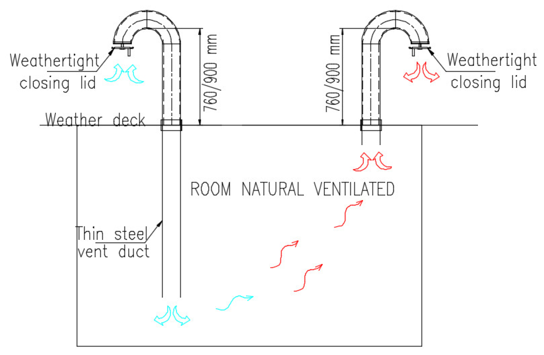
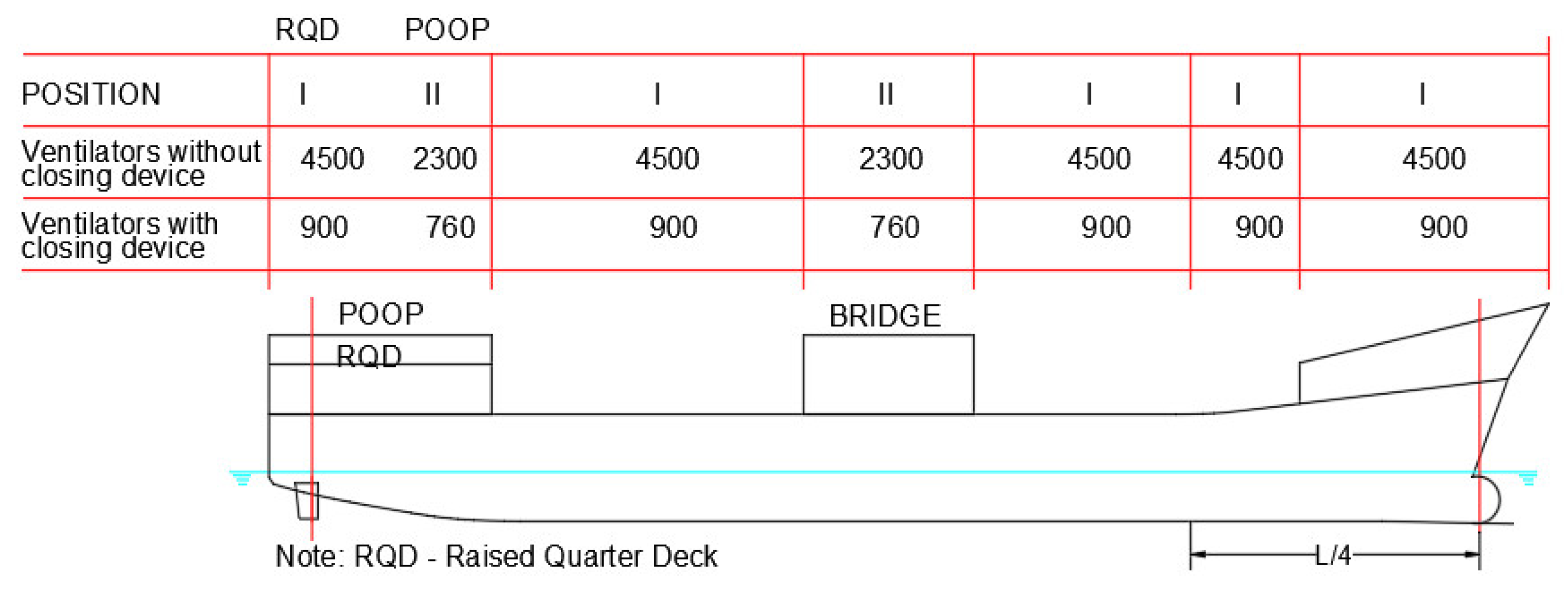
In general, technical compartments with no specific requirements for the operation of equipment or the safety of the ship and passengers are provided with independent natural ventilation. To improve the natural circulation, inlet grilles are placed at the bottom of the compartment and exhaust grilles are placed at the top. In Figure 1, a typical natural ventilation system for a room located below the weather deck is presented. The ventilation openings are located above the weather deck at a minimum height of 900 mm in position 1 and a minimum of 760 mm in position 2 according to International Maritime Organization (IMO) load line requirements [9].
2.2. Independent Mechanical Ventilation
According to the requirements of the Classification Society [10,11,12,13], the technical and cargo compartments of the ships are provided with independent mechanical ventilation systems equipped with supply or exhaust fans. The ventilation system provided for these compartments must ensure the cooling of the room, the necessary air for operation of the equipment, and remove the flammable gases that can accumulate inside the room. In certain situations, the ventilation systems are supplemented with local cooling systems provided with fan coils with 100% recirculation.
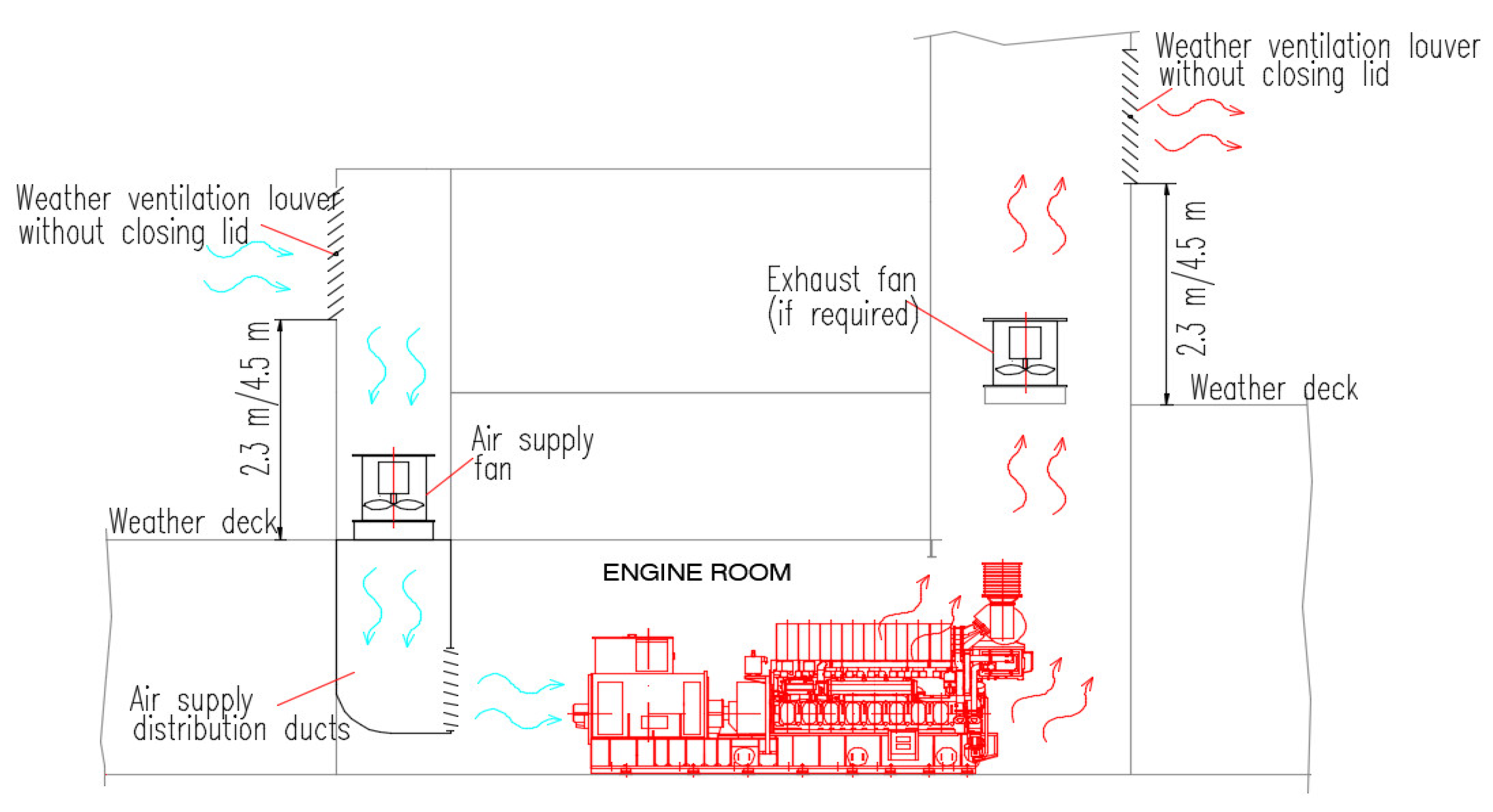
Sometimes, both exhaust and air supply fans are provided to ensure the desired pressure inside the compartment. In Figure 2, a typical mechanical ventilation system for a room located below the weather deck (with supply fan, exhaust fan, and both supply and exhaust fans) is presented.
In the case of the engine room, the openings on the weather deck should be kept without a closing device. In Figure 3, a typical example of ventilation for the engine room is presented. In this case, according to the IMO load line requirements [9], the openings should be located at a height of a minimum of 4.5 m above deck in position 1 and a minimum of 2.3 m in position 2.
2.3. Common Mechanical Ventilation for Several Rooms, Combined with Air Conditioning System
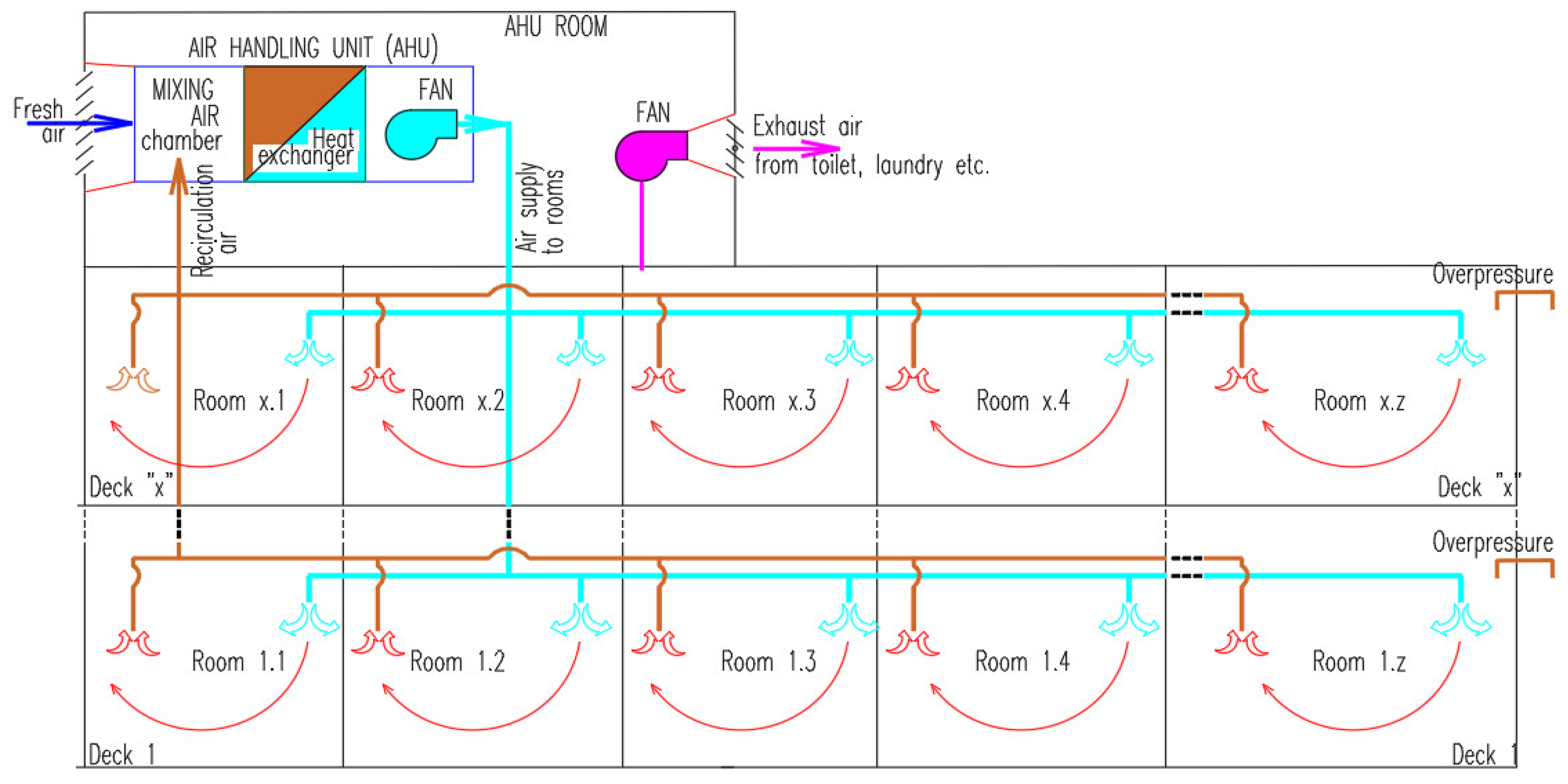
In the case of living spaces, in general, common ventilation and air conditioning systems are used to ensure the cooling or heating of the compartments as well as the requested fresh air. The air is recirculated through the air handling unit (AHU) back to rooms for cooling/heating purposes. Figure 4 shows a common usual ventilation and air conditioning system where the fresh air is mixed inside the AHU unit with air recirculated from the room served.
To increase the efficiency of the system, some energy can be recovered from the exhaust air but the possibility to recover the energy is not always profitable, as concluded by Zender–Swiercz [14].
In the case of small ships and boats, the common air handling unit (AHU) is replaced by local small fan coils and local fresh air connections, without air recirculation from different rooms (see Figure 5 for reference).
3. Review of Main Rules and Requirements for Ventilation of Different Compartments
The ventilation of ship compartments is carried out based on the requirements of the classification society rules, IMO rules, and international standards.
3.1. General Requirements
In general, the Classification Societies require the following information to check and approve the ventilation systems installed on the ships [10]:
- Machinery spaces and technical spaces—ventilation system
- Accommodation and service spaces (galleys, pantries, lockers, etc.)—ventilation and air condition diagrams
- Cargo spaces—ventilation system including hazardous areas if applicable
- Details of fire dampers and weather-tight dampers and approvals
- Details for duct penetrations and approvals
According to Classification Societies rules [10], which follow IMO rules [15], the ventilation systems for machinery spaces of category A, vehicle spaces, ro-ro spaces, galleys, special category spaces, and cargo spaces should be separate from each other’s and should be separate from the ventilation systems serving other spaces. There is an exemption for the ventilation system of the galley in the case of cargo ships with a gross tonnage below 4000 and for small passenger vessels carrying a maximum of 36 passengers.
The penetration through watertight and fire divisions should be kept at a minimum and the watertight/fire integrity should be kept unaffected.
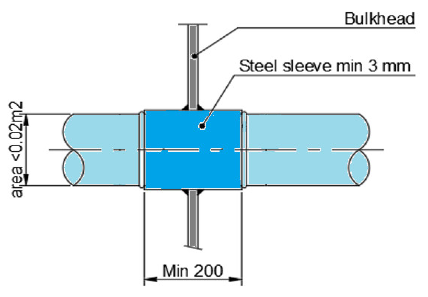
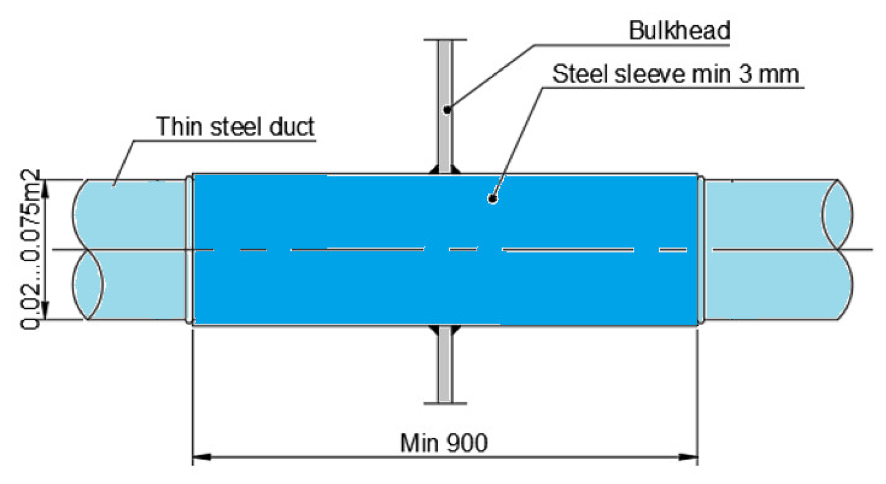
According to IMO—SOLAS rules [15], in case a thinly plated ventilation duct penetrates a fire deck/bulkhead, the penetration sleeve should have the length and minimum thickness outlined in Figure 6, Figure 7 and Figure 8.
The requirements regarding avoiding flooding through the ventilation system are indicated in Figure 9 [9,16,17,18].
Strength requirements for ventilation ducts located on the weather deck.
In the case of vessels with a length of 80 m and above, the ventilation ducts located on the weather deck in the forequarter of the vessel must respect the strength requirements from the International Association of Classification Societies (IACS) Unified Requirements (UR) S27 [19].
Avoiding explosions in hazardous areas.
In hazardous areas, fans with anti-explosion protection are installed and the ventilation openings should be provided with a protection screen of a minimum of 13 mm square mesh to prevent objects from entering the fan [10,11,13,20]. The ventilation openings for other compartments should be located far from hazardous areas.
3.2. Main Ventilation Requirements for Different Compartments
The ventilation system for machinery spaces is provided with supply and exhaust fans with high airflow, which should ensure a maximum of 45 °C RH60% inside the room [21,22].
For ships not certificated for unrestricted services, the Classification Society can approve an increased temperature inside the engine room [23].
The airflow needed for the ventilation of the engine room should be calculated according to ISO standard 8861 [21]. The equipment makers also have some requirements and recommendations; however, to obtain a good efficiency of the ventilation, detailed computational fluid dynamics (CFD) analyses could be necessary [24].
In addition according to Classification Societies rules [13,25] the gas tank connection space and fuel preparation room should be provided with extraction type ventilation with a rate of at least 30 changes per hour.
In general, the engine control rooms are provided with dedicated ventilation and air conditioning systems that must keep the temperature below +27 °C, considering the heat dissipation from equipment installed inside and moderate fresh air exchange rate [26].
The compartments wherein flammable liquids are stored must be provided with an independent ventilation system that ensures at least 10 air changes per hour [10].
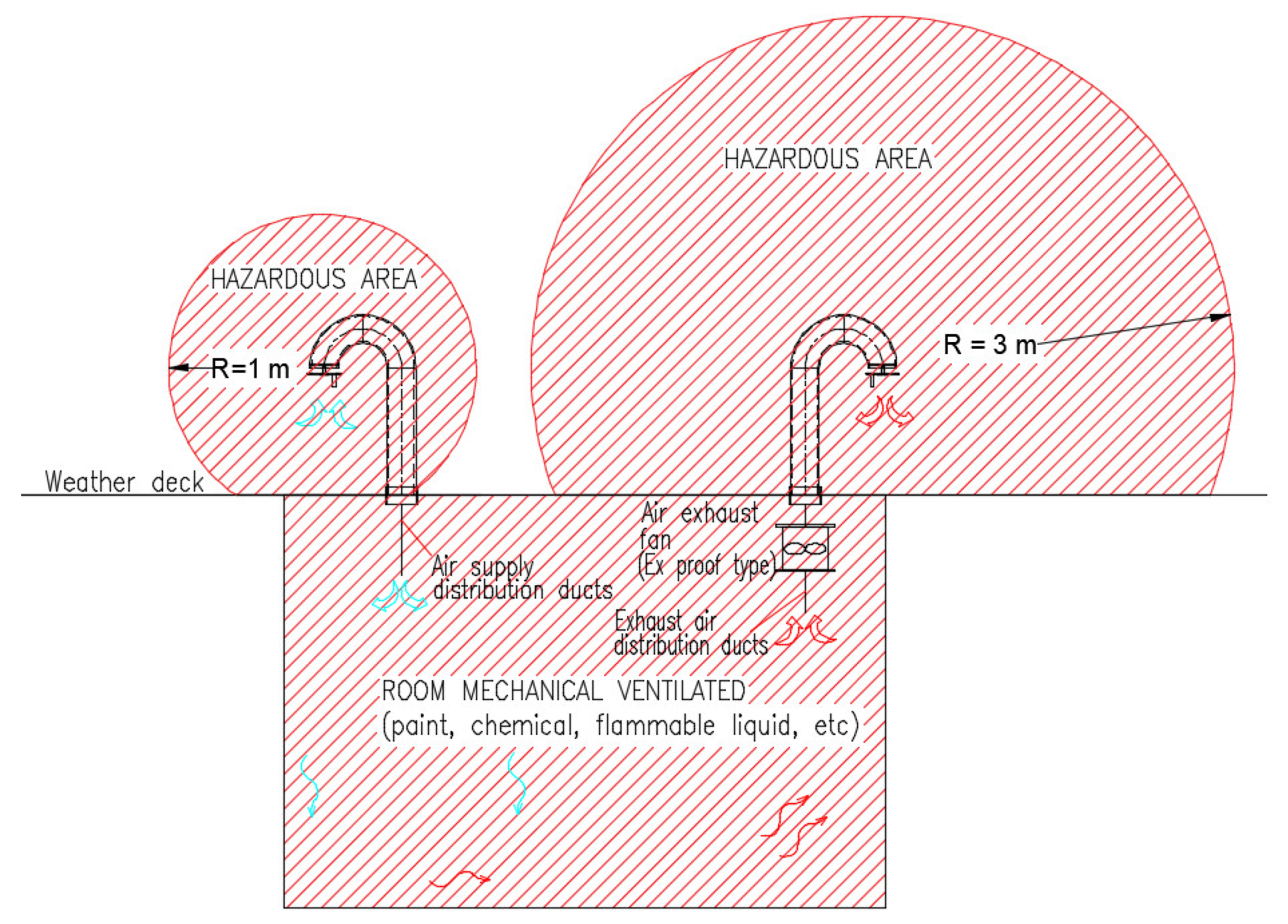
Figure 10 presents a typical example of ventilation for flammable store compartments with extended hazardous areas. The ventilation openings for other systems should not be installed in the extended hazardous area indicated in Figure 10.
For oxygen-acetylene storage rooms and CO2 rooms, the independent ventilation system ensures a minimum of six air changes per hour and for refrigerating machinery and at least 30 air changes per hour for the battery rooms [10,11].
In case the fan is installed at a distance less than 3 m from the exhaust outlet, it should be a safe type [27].
The galley is provided with a mechanical ventilation system with the fresh air supply and exhaust fan calculated according to ISO standards [28].
The wheelhouse should be provided with a ventilation and air conditioning system calculated according to ISO standard 8864 [29].
In general, the ventilation system should ensure a small positive pressure inside the room [29].
3.3. Additional Requirements for Dedicated Vessels
All enclosed spaces containing livestock should be provided with mechanical ventilation with a capacity of not less than 20 changes per hour.
The cargo pump rooms for oil tankers and FLS tankers are provided with an exhaust ventilation system that ensures a minimum of 20 air changes per hour, but in the case of oil recovery ships, only eight air changes per hour are required [30].
In the case of liquefied gas carriers, the exhaust ventilation openings from a hazardous area should be located at a distance of at least 10 m in the horizontal direction against other openings from non-hazardous spaces.
The public atriums spaces in passenger’s vessels should be provided with an extraction ventilation system with the capacity to remove the smoke in a maximum of 10 min, according to Maritime Safety Committee (MSC)/Circ 1034 [31].
In the case of inland navigation passenger vessels, at least two separated gas-tight engine rooms with dedicated independent ventilation should be provided [32].
In the case of ro-ro vessels, the ventilation of the cargo spaces, where vehicles provided with internal combustion engines can be driven, is calculated and arranged according to ISO standard 9785 [33].
The ventilation system should ensure a minimum of 10 air changes per hour, but during loading and unloading the airflow should be increased to 20 air changes per hour, according to the International Convention for the Safety of Life at Sea (SOLAS) [15] requirements and Det Norske Veritas—Germanischer Lloyd (DNV-GL) interpretation [20].
In the case of ships operating in polar water, the air intake ventilation openings should be located on both sides of the ship [34].
4. Main IMO and Classification Societies Requirements and Guidelines for the Management of COVID-19 and Infectious Diseases
The International Maritime Organisation (IMO) and its member states are analyzing the impact of pandemic COVID-19 to find a solution for the prevention and control of infectious diseases, but these measures are related in general to seafarer movement across the border, protection of personnel, etc., and there are no rules or solutions for the construction and updating of the vessel’s systems, which can spread the disease.
The Classification Societies have also provided guidelines for the management of COVID-19 and infection diseases on board the ship. Heating, ventilation, and air conditioning systems (HVAC) are considered by Classification Societies [35] as “an extremely complex system in an infectious protection environment … It is likely to be necessary to have a separate HVAC strategy”.
According to class requirements, the owner or others responsible for vessel operation must analyze and understand the existing HVAC systems installed on the vessel “in line with future developments” [35] and take the appropriate measures to reduce the risk of infection. The Classification Society mentions that “it is not necessarily a requirement for ongoing expensive upgrade and replacement, but rather an understanding of how future designs seek to reduce risk and how such concepts may influence existing designs” [35].
Related to existing ventilation systems, Classification Societies recommend taking all reasonable measures to avoid propagation along with the system. The reasonable measures considered include the “introduction of clean air, reducing or cancelling recirculation and increasing filtration at reasonable cost” [35].
In addition to IMO and Classification Societies requirements and guidelines for the management of COVID-19 and infectious diseases on board the ships, there are also other authorities, agencies, and professional associations that provide standards and guidelines for the design and operation of the HVAC system in general. Below is a selection of the main institutions that have analyzed the HVAC operation issues and provided guidelines during the COVID-19 pandemic:
- American Society of Heating, Refrigerating and Air-Conditioning Engineers (ASHRAE),
- Federation of European Heating, Ventilation and Air Conditioning Associations (REHVA),
- European Centre for Disease Prevention and Control (ECDC),
- Canadian Committee on Indoor Air Quality (CCIAQ),
- Architectural Society of China (ASC),
- Society of Heating, Air-Conditioning and Sanitary Engineers in Japan (SHASE),
- Indian Society of Heating, Refrigerating and Air Conditioning Engineers (ISHRAE)
- Public Health Ontario (PHO),
- Chinese Association of Refrigeration (CAR),
- National Health Commission of China (NHC).
5. Ventilation and Air Conditioning Systems for Living Spaces
5.1. Environmental Conditions According to ISO Standard
The ventilation and air conditioning systems for accommodation are calculated and designed according to ISO standard 7547 [1]. The ventilation and air conditioning system should be designed to ensure the following indoor conditions based on the indicated outdoor air conditions and minimum outdoor air supply of “40% of the total air supplied to the spaces concerned” [1].
- Summer—temperatures and relative humidity:
| Outdoor air | +35 °C and 70%RH |
| Indoor air | +27 °C and 50%RH |
- Winter—temperatures
| Outdoor air | −20 °C |
| Indoor air | +22 °C |
5.2. Influence of Outdoor Air, Heat Gain, and Heat Loss on the Capacity of Ventilation and Air Conditioning System
The capacity of the ventilation and air conditioning system is calculated according to ISO standards considering the requested outdoor fresh air and the heat gain loss, as follows:
5.2.1. Heat Gain and Loses
According to ISO Standard:
- Heat transfer through the ceiling, walls, and floors have a low impact on total heating/cooling power, considering that all these areas are provided with heat insulation with an overall heat transfer coefficient of 0.4 to 0.9 W/m2K.
- Heat transfer through windows. The overall heat transfer coefficient is 2.5–6.5 W/m2K but the impact on the total heating/cooling power is also reduced because the area of windows on the ship is reduced.
- Solar heat gain. It is calculated for all exposed bulkheads and decks where the temperature is increasing above the air temperature with 12 °C for vertical light surfaces, 29 °C for vertical dark surfaces, 16 °C for horizontal light surfaces, and 32 °C for horizontal dark surfaces. However, this increased temperature has a low impact on the total cooling power because the bulkhead and decks are thermally insulated.
- Solar heat gain by solar radiation through windows. The total heat gain is calculated based on the total area of windows and solar radiation coefficient which is considered 350 W/m2 in the case of clear glasses and 240 W/m2 if the glasses are provided with interior shading. The heat radiation has a big impact on the cooling power for the rooms provided with large windows such as wheelhouses and other special spaces in passenger’s vessels. To reduce the impact of the sun radiation, the windows can be provided with glasses with a high reflection capacity for infrared radiation. Additionally, different solutions for exterior and interior shading are used.
- Heat gain from persons and equipment. The heat gain from persons, in general, has a low impact on the cooling system, except the public spaces designed for a high number of persons.
- Heat gain from equipment. The heat gain from equipment is insignificant in living spaces.
5.2.2. Outdoor Air Supply
The outdoor air supply is requested to permit the air extraction from toilets, laundry, the galley, changing rooms, hospital, etc., and to ensure the requested fresh air of a minimum of 28.8 m3/person. In addition, according to ISO standards, the fresh air rate should be increased to over 40% from total airflow. In general, this requirement increases the total cooling and heating power for the air handling unit.
However, it can be concluded that the cooling/heating capacity of the air conditioning system is mainly determined by the quantity of fresh air that should be cooled or heated and humidified or dehumidified. Therefore, from an energy point of view, it is very important to recover the energy from the exhaust air. This issue is even more important in the conditions of cancelling the air recirculation.
In general, the following heat recovery devices are used for HVAC systems:
- (a)
- Rotary wheel heat recovery exemplified in Figure 11 is the most used solution for air handling units, which can have an efficiency of up to 85%. There is also a small energy consumption for rotating the wheel, but it has little effect on the recovery device efficiency. The pressure drop across the wheel heat recovery is about 200 Pa but it can be a higher or lower function of the size of the wheel and a function of the air velocity. The main disadvantage of this device, especially related to the spread of diseases, is that the two sides are not gas-tight; therefore, leakage of exhaust air to fresh air is expected.
- (b)
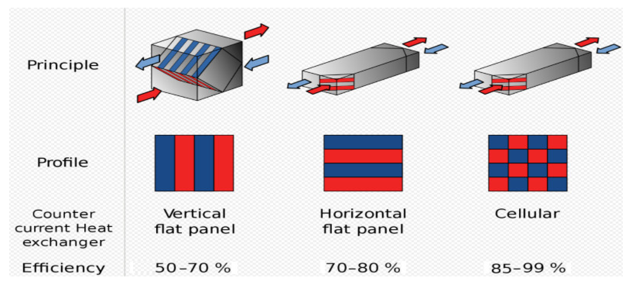
- Fixed plate heat recovery, exemplified in Figure 12, has a good efficiency, which can reach up to 90%; however, the main disadvantage is that the pressure drop is high and can increase in cold weather when the frost limit is exceeded and the condensate inside the heat exchanger freezes. Regarding the leakage of exhaust air to fresh air, these heat recovery devices are very leak tight. According to Hoval’s handbook [37] the leakage between supply and exhaust sides is below 0.1%, for a pressure difference of 250 Pa; therefore, it can be considered that there is no cross-contamination.
- (c)
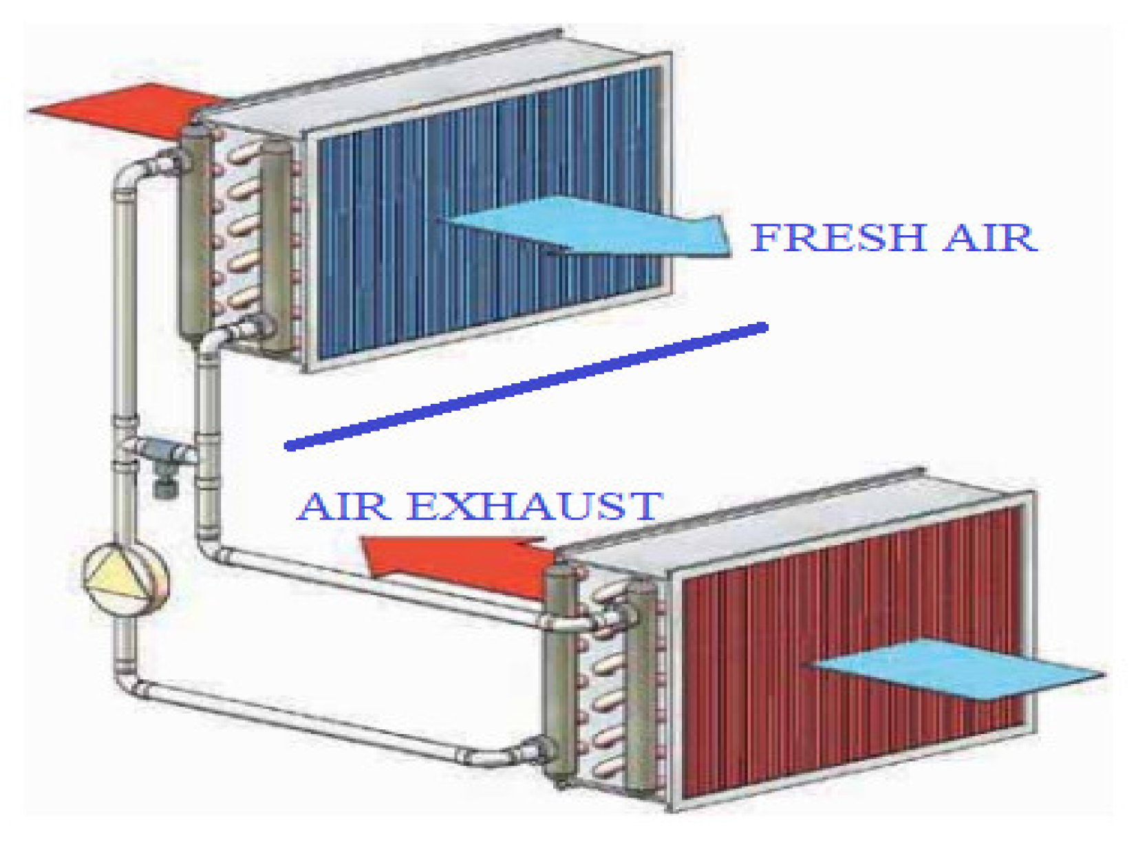
- Round around coil-type heat recovery systems, exemplified in Figure 13, have a lower efficiency than those presented above, increased cost, and need a separate system with a pump and control system. Its advantages include the low pressure drop and no mixing between fresh air and exhaust air.
- (d)
- Heat pipe-type heat recovery systems are similar to coil-type systems but need a refrigerant system instead of water. Its advantages include the low pressure drop and no mixing between fresh air and exhaust air.
In their study, Zheng et al., 2021 [40] summarized the recommendation of different institutions regarding heat recovery devices:
- ASHRAE considers that the fact that “heat recovery devices can be utilized for leakage is acceptable”.
- REHVA, ECDC, and SHASE consider that “heat recovery devices can be utilized for leakage […] below 5%”.
- CCIAQ and PHO consider that “cross-contamination between outdoor air and exhaust air should be avoided with the application of heat recovery devices”.
- ASC, NHC, and ISHRAE consider that “Rotary heat exchangers should not be applied.”
In general, the HVAC system for living spaces is provided with a common air conditioning system that ensures the necessary fresh air and heating or cooling of all living spaces. In the case of big ships, such as passenger vessels or special vessels with a large number of people on board, two or more independent air handling units (AHU) are provided for each main fire vertical zone. Each air handling works with 40–60% fresh air and 60–40% recirculation air from the served rooms.
5.3. Spread of Diseases on the Ships
By air recirculation from all rooms and mixing inside the AC unit, the viruses from one space are distributed in all living spaces.
In the case of the Diamond Princess Cruise Ship, a lot of persons were infected with COVID-19 in a short time, even if the vessel and the people on board quarantined from the first 10 cases confirmed.
Eisuke et al. [41] chronologically analyzed the evolution of the COVID-19 pandemic on the Diamond Princess Cruise Ship and indicated that over 600 persons (over 15% from the total people on board) were infected in the first two weeks, from 5 February to 19 February, even though it was decided to start the quarantine on 5 February.
Gupta A et al. [42] concluded that “it is just impossible to segregate infected from the non-infective in a space-constrained, air-conditioned setting” and mentioned that the quarantine on board the ship is not efficient.
Parham et al. [43] concluded in their study that “aerosol inhalation was likely the dominant contributor to COVID-19 transmission among passengers aboard the Diamond Princess Cruise Ship even with a very high ventilation rate (9–12 air changes per hour) and no recirculated air”.
Hwang et al. [5] analyzed “Possible aerosol transmission of COVID-19 associated with an outbreak in an apartment in Seoul, South Korea, 2020” and concluded that the virus spread upstairs and downstairs through the ventilation duct, indicating aerosol transmission. Priyanka et al. [6] reported aerosol transmission of SARS-CoV-2, especially in enclosed spaces, due to that aerosols being suspended for a long time and travelling via airflow. Kulkarni et al. [44] have analyzed the spread of diseases with respiratory syncytial virus (RSV) and concluded that aerosol particles of RSV remained airborne for a long time and led to transmission of the infection. In his study, Melikov [45] highlighted that aerosol transmission should be considered; otherwise, it is difficult to control the spread of diseases. Corea et al. [46] consider the HVAC system “as a major source for indoor and environmental contamination”.
Therefore, we can conclude that in the case of common air conditioning systems provided with recirculation, the closing of air recirculation after discovering a new infection will not solve the problem while the entire system is already contaminated and cannot be easily cleaned and disinfected.
5.4. Measures to Reduce the Risk of Disease Transmission through the HVAC System
It should be concluded that to avoid the spread of diseases through the ventilation system onboard the ship, the following solution can be adopted:
- Common ventilation system with HEPA filters or UV disinfection
The common air conditioning and ventilation systems for living spaces can be provided with mechanical filtration. Unfortunately, the HEPA filter can remove 90–99.9% of the particle at 0.3 μm in size [47] but “most viruses, including CoVs range from 0.004 to 1μm” which can be interpreted that HEPA filtration will not offer complete protection [2]. However, most viruses, including SARS-CoV-2, are combined with water and other components as droplets and aerosols particles with size of 0.25–0.5 μm [2]. In this case, the HEPA filters “play an important role in virus exclusion and hence lowering the transmission potential of SARS-CoV-2 within the pharmaceutical and healthcare setting” [2]. The spread of diseases through the air conditioning system can be reduced by adding HEPA filters, but in this case, the protection is limited and the fans should have increased pressure. In general, the air handling units are provided with filters that have a “minimum efficiency reporting value (MERV)” of 7–8 and ASHARE recommends filters rated MERV-13 or higher [2,48]. The pressure drop across these filters is about 30 Pa when the filters are clean and can increase to 300 Pa when the filters are dirty [49]. The existing filters can be replaced with HEPA filters or the existing filters can be kept as pre-filters to avoid rapid clogging of the HEPA filter. The pressure drop across the HEPA filters is about 150–300 Pa [49,50] when the filters are clean. According to the manufacturer’s recommendation [49], the final pressure drop could be two to three times the initial pressure drop. However, although the manufacturer accepts a maximum pressure drop of 450–900 Pa across the HEPA filters, the system should be designed so that the total pressure drop is kept as low as possible to avoid high energy consumption and to keep the total pressure drop in line with available standard fans, which in general is 1200–2200 Pa [51].
According to the United States Environmental Protection Agency [52], the pre-filters should be replaced every 60 to 90 days, but the manufacturer’s recommendation must be checked and followed. In general, HEPA filters cannot be cleaned and should be changed after one month up to one year [53]. In any case, the filter should be checked and cleaned/changed every time it becomes clogged; therefore, it is recommended to be provided with pressure drop measuring devices.
Figure 14 presents a typical example of a ventilation and air conditioning system, with recirculation and air mixing, provided with HEPA filters on the main supply duct and recirculation duct. The solution with HEPA filters installed on both the supply and the recirculation ducts could increase the protection while there are two stages of filtration. If the air recirculation is contaminated, the viruses are filtered on the main recirculation line; therefore, the fresh air will be mixed with almost clean air. Finally, the HEPA filter installed on the supply main distribution duct will clean the viruses or bacteria that escaped from the first stage of filtration or if outside fresh air is contaminated. Although the two HEPA filters increase the protection, the increase of the total pressure drop due to the second filter should be considered. If the total pressure drop increases, the final pressure drop of the filter after clogging should be reduced; therefore, the filters will need to be changed more often. In addition, if the recirculation line is provided with a HEPA filter, the pressure inside the rooms will increase with the backpressure of that filter. Taking into consideration a back pressure of 150–900 Pa across the HEPA filter, it is mandatory that the system be provided with a recirculation (exhaust) fan so that the pressure inside the room is kept in accordance with the requirements (e.g., −50 to +50 Pa). Regarding the pressure inside the accommodation area, it is necessary that the system be designed/balanced to keep the same pressure in all rooms, corridors, and common spaces so that natural circulation between different rooms/corridors is reduced to a minimum.
The solution indicated above can be simplified by cancelling the HEPA filter installed on the recirculation line, but in this case, the contaminated air is mixed with the fresh air and introduced into the AHU unit. The filtration occurs on the main supply ventilation duct only. The solution will be simpler when the recirculation (exhaust) fan is no longer mandatory.
Another solution is to keep the recirculation HEPA filter and to cancel the main air supply HEPA filter. In this case, the contaminated air is not mixed with fresh air and does not enter the AHU unit anymore, but the recirculation (exhaust) fan is mandatory. It should also be mentioned that the recirculation filter is 40–60% smaller than the main supply filter because the recirculation airflow is in general 40–60% lower than the supply airflow.
In case the recirculation and/or main supply HEPA filters cannot be installed, the filtration can be carried out locally by adding small HEPA filters in the supply line/diffuser of each room. Regarding installation and maintenance, this solution has the disadvantage that all rooms are affected when changing the filters and the time, costs, and discomfort will increase during filter replacing. Regarding the functionality, the system becomes unbalanced more easily due to the big pressure drop across the HEPA filters, which can easily change the airflow rate if the clogging rate of the filters is different between different rooms. The filter clogging rate is different due to different initial airflow rates or if the flow rate can be adjusted inside each room.
To reduce the risk of disease transmission through the HVAC system, Jones et al. [54] highlight the ultraviolet lamp’s “(UV-C’s) potential as an effective air and surface disinfectant”. The ultraviolet lights can be used as a separate system or together with HEPA filters to reduce “and even prevent the growth of dangerous microbes in HVAC systems” [54].
In their article, Vranay et al. [3] concluded that by using a UV-C disinfection system, “more than 90% of the SARS-CoV-2 virus produced by humans in the internal environment can be inactivated”. Additionally, according to their analysis, the energy consumption for disinfection with UV-C lamps was about 2.3% of the total energy consumed by the HVAC system.
In their article, Kowalski et al. 2020 [55], based on hundreds of laboratory studies, demonstrated that ultraviolet light is capable of inactivating viruses, bacteria, and fungi. The author has summarized the result of the exposure of coronaviruses to ultraviolet light and concluded that 90% (D90) virus inactivation is obtained for a radiation dose of 7–241 J/m2 with an average of 67 J/m2. Table 1 presents a summary of ultraviolet studies on coronaviruses according to Kowalski [55].
According to the Illuminating Engineering Society, 2020, [4] ultraviolet light has a spectrum of 100–400 nanometers (nm), and the most effective for disinfection is “UV-C” with a wavelength from 200 to 280 nm. According to ASHRAE [56], the maximum efficiency of the UV disinfection is for a UV-C wavelength of 265 nm. It should be noted that “a by-product of UV-C radiation with a wavelength of 185 nm is ozone” [3], which is a strong oxidant and harmful to health in high concentrations, but this emission is absorbed by glass, which is used for this kind of application. In practice, UV lamps generate about 90% of energy close to 254 nm [57]. Regarding UV-B lamps (280–315 nm), it should be mentioned that they can also be effective for disinfection, but this UV light penetrates the skin more deeply; therefore, in the case of accidental exposure, it is more dangerous. The UV-A (315–400 nm) is not capable to inactivate the viruses.
The efficacity of UV disinfection is proportional to the UV exposure dose (J/m2), which represents the product of the irradiance rate (W/m2) and time (s). It should be mentioned that there is a nonlinear relationship between UV exposure and germicidal efficacy. Therefore, if the exposure time is increased by 50%, the efficiency of disinfection will increase from 90% to 99% [4]. Another aspect that should be considered when designing the UV system is the humidity, which can reduce the efficiency of UV disinfection.
In in-duct systems, the exposure time is low (seconds or fraction of seconds); therefore, the UV irradiance rate should be high enough to produce the requested dose needed to inactivate the viruses in seconds or fraction of seconds, according to air velocity. To increase the effective UV dose, the inside of the air handler is provided with high reflective materials such as aluminum and other highly reflective materials, which will reflect the UV energy into the irradiated area. According to ASHRAE [56], in the general in-duct system, the requested average irradiance is 1000–10.000 μW/cm2. Regarding the location of the UV lamps, they can be installed anywhere inside the HVAC system, but some locations can improve the UV disinfection system. In general, the most suitable place is inside the air handling unit (AHU) due to the low air velocity, at the same time also ensuring the irradiation of the cooling coils. To avoid increasing the system cost and power consumption, ASHRAE [56] recommends that the in-duct system be located so that the UV air exposure is a minimum of 0.25 s. The location of the UV system should be decided also keeping in mind that the UV system will need periodic inspection, maintenance, and lamp replacement. In general, the UV lamps have a rated life of 9000 h of operation; therefore, the lamps should be changed annually if they run continuously. However, in function of the ballast type used, if the lamps are often switched on/off, the lifetime of the lamps can be reduced. Nevertheless, the UV lamps can operate after the lifetime indicated by the manufacturer, albeit with reduced performance.
Morawska et al. [58] highlighted that air recirculation is a measure for saving energy but it increases the risk of airborne infection; therefore, the recommendation is to cancel air recirculation. Air cleaning and disinfection by ultraviolet irradiation may offer benefits and it is recommended where it is difficult to improve the HVAC system.
Federation of European Heating Ventilation and Air Conditioning Associations (REHVA) [59] and the European Centre for Disease Prevention and Control recommends cancelling central air recirculation to avoid the spread of COVID-19 aerosols through the HVAC system.
In case the air recirculation cannot be cancelled, it is recommended to increase the fresh air supply as much as possible in addition to HEPA filter or ultraviolet disinfection, devices to be provided in the main air duct. However, the solution with a high-class filter (e.g., HEPA filter) is recommended, if this is technically possible [59]. If the HVAC system cannot be improved by cancelling air recirculation, the Canadian government [60] recommends HEPA filtration.
- 2.
- The common fresh air supply system and local individual cooling and heating
The common AHU unit is replaced with a smaller one, which will ensure the requested fresh air only. The heating and cooling of the room is carried out locally by using local small fan coils or other local air conditioning equipment. In this case, the recirculation of air from one room to another room, and the spread of diseases through the HVAC system, will be cancelled. This system also has other advantages, such as smaller ventilation pipe sizes, the big AHU unit being replaced with a smaller one, and HEPA filters not being necessary; therefore, the pressure of the fans should not be increased, the control of temperature inside the room is better, etc. The main disadvantage is that each room should be provided with a small local fan coil to ensure the necessary cooling and heating of the room and these can generate additional noise. In addition, the total price of the system could be higher. Figure 15 proposes a typical example of an individual ventilation and air conditioning system, without recirculation and air mixing and HEPA filters. From an energy point of view, the solution can be improved with heat recovery devices without leakage between the supply and exhaust air. The heat recovery system increases the initial cost, but it is amortized over time and the energy consumption and pollution is reduced.
Another solution that should be analyzed for the new vessels with many passengers is to provide different gas-tight zones with dedicated air handling units. These zones can be easily split by main fire vertical zones; however, in addition, some small separate gas-tight areas should be provided in hospital and sickbay areas for quarantine purposes. The intake and especially exhaust air for each gastight area should be located so that air recirculation between different HVAC systems is not possible. In addition, the intake and exhaust openings should also be located far from the other vessel hazardous areas.
According to ASHRAE [56] another effective and low-cost solution is to provide upper-air UV-C devices inside the rooms. As indicated in Figure 16, this solution is applicable in rooms with high ceilings to keep the UV disinfection zone above the minimum safe area of 7 ft [56]. This disinfection solution will be very useful in the quarantine area and large common spaces on the vessel; therefore, these spaces should be designed with high ceiling elevation.
In case of an unwanted epidemic on board a ship, an emergency plan is necessary to avoid the spread of the infection, as are devices and tools to control the disease. Therefore, in addition to the new design for the HVAC system, other devices and tools such as disinfection tools, protective suits, masks, gloves, etc. should be provided in the inventory of each ship, sized according to the number of people on board.
There is different mobile UV disinfection equipment on the market in general for shore applications, but they can be certificated also for marine applications. According to American Ultraviolet [61] the mobile UV unit type MRS45-12, which weighs 43 kg, can inactivate coronavirus at 99.9%, at a distance of 3 m in less than 1 min. In the same way, the mobile UV unit type MRS33-8 [62], which weighs 36 kg, can inactivate coronavirus at 99.9%, at a distance of 3 m in less than 2 min. Smaller units can also be used if the weight should be reduced to be easier to transport, but the time of disinfection will increase.
6. Discussion
The existing vessels all have compartments provided with natural and mechanical ventilation. In general, the technical spaces are provided with independent ventilation and a high rate of air exchange; therefore, the spreading of viruses in these compartments is not an issue.
Unfortunately, it is different for living spaces, especially in large ships, which are provided in general with a common air conditioning system with air recirculation. Taking into consideration that HVAC systems are not provided with efficient filtration against viruses, the spreading of diseases in all living rooms is becoming a big issue for actual air conditioning and ventilation systems on the vessels.
COVID-19 has shown us that the effects of a new virus can be quite harsh for people’s health and freedom. Therefore, the article intends to point out the need for a new approach to the solution for ventilation and air conditioning systems for living spaces. The standards, Classification Societies rules, IMO rules, and administration requirements regarding ventilation and air conditioning systems onboard the ships should be analyzed and revised so that the possibility of spreading viruses through these installations is reduced as much as possible.
IMO and Classification Societies are concerned about the COVID-19 pandemic and the spread of diseases aboard the ships. However, even if the Classification Societies consider that the HVAC system is “an extremely complex system in an infectious protection environment” and “it is likely to be necessary to have a separate HVAC strategy” [35], there are no clear rules and requirements regarding the necessary changes. The Classification Societies shifted the responsibility for finding the necessary solutions to the owner and other vessel operators. They must analyze and understand the existing HVAC systems installed on the vessel “in line with future developments” [35] and take measures to reduce the risk of infection.
Regarding the existing ventilation system, Classification Societies recommend “reducing or cancelling recirculation and increasing filtration at reasonable cost” [35]. For actual common HVAC systems, in general, the recirculation cannot be cancelled because the system will no longer be able to ensure the efficient cooling or heating of the rooms, while they are designed for recirculation of 40–60% from total airflow. However, if the heat exchanger has enough spare power to ensure the cooling/heating of the room with fresh air only, the energy consumption will increase significantly. Zheng et al. [40] highlighted in their study that “during the pandemic the energy consumption of HVAC systems increases by 128%” according to the study in China. This article presents two solutions to reduce the risk of spreading viruses between different rooms through the HVAC system, solutions which are in line with Classification Societies recommendation.
The first solution, shown in Figure 11, can be used for existing ships by providing HEPA filters in main recirculation and/or main supply ducts. In this case, the fans should be checked, and if the pressure available is not enough, the fans should be replaced. The HEPA filters can have a final back pressure of 450–900 Pa and in addition pre-filters (with a final pressure drop of abt. 300 Pa) are recommended to avoid rapid clogging of HEPA filters. The total pressure drop will then increase quite a lot; therefore, the solution with two stages of HEPA filtration becomes difficult to implement. It should be noted that the pressure drop inside the rooms will increase substantially if the HEPA filter is installed on the recirculation duct; therefore, an exhaust fan must be provided. The HEPA filters can be added to the supply line in each room, but in this situation, it is more difficult to keep the system balanced due to the high-pressure drop of the HEPA filter when clogging.
In addition, UV lamps can be added to improve the disinfection of the air inside the HVAC system. The UV disinfection can have good efficiency, but the main challenge is to ensure the exposure time of a minimum of 0.25 s, which means that a large space is needed to keep the air velocity low. Otherwise, the UV lamps can be installed anywhere inside the HVAC system.
Another effective and low-cost solution for large rooms with high ceilings, in addition to the HVAC UV disinfection system, is to provide inside the rooms upper-air UV-C devices.
The second solution, shown in Figure 12, is a proposal based on individual HVAC systems used on small vessels and boats, which was improved with a fresh air system. In this case, the spread of disease through the HVAC system between different rooms could be eliminated. The solution can be analyzed for new vessels or in case of large conversion because it will need changes in all rooms. It can be feasible also in case the existing vessel is not working in areas with high temperatures and the cooling can be carried out with fresh air only. In this case, the local fan coils can be replaced with electrical heaters.
A solution to improve the system from the energy point of view is to recover the energy from the exhausted air and to transfer it to the fresh air but without contamination of the fresh air. There are different solutions for heat recovery, some of them without cross-contamination and low-pressure drop (e.g., heat pipes and run-around), but these are more expensive to implement and have some particular requirements for air temperatures. Another solution (fixed plates) has a high-pressure drop which can increase more in case of cold air. One of the most used solutions (rotary wheel) has quite a large leakage and the fresh air can be contaminated by exhaust air; therefore, it is not recommended in the case of epidemy.
To improve protection in case of epidemy, especially for ships with a large number of passengers on board, the vessel should be split into more gastight zones, which can be quite easily executed by existing fire vertical zones. In addition to these, an emergency plan to avoid the spread of diseases onboard and a separated gas-tight space which can be used for quarantine purposes in case of epidemy should be provided. Additionally, mobile UV disinfection units should be added to the inventory of each ship to be used for disinfection of the rooms previously occupied by sick people. In future works, the aim is to make a budget comparison between different alternative solutions in the case of existing vessels and for a new ship.
Author Contributions
Conceptualization, investigation, visualization, methodology and writing—original draft preparation, V.M.; supervision, formal analysis, writing—review and editing, L.R. All authors have read and agreed to the published version of the manuscript.
Funding
The work was carried out in the framework of the research project DREAM (Dynamics of the REsources and technological Advance in harvesting Marine renewable energy), supported by the Romanian Executive Agency for Higher Education, Research, Development and Innovation Funding—UEFISCDI, grant number PN-III-P4-ID-PCE-2020-0008.
Acknowledgments
This work will also be presented to the 9th edition of the Scientific Conference organized by the Doctoral Schools of “Dunărea de Jos” University of Galati (SCDS-UDJG) http://www.cssd-udjg.ugal.ro/ (accessed on 10 July 2021), which will be held on 10–11 June 2021, in Galati, Romania.
Conflicts of Interest
The authors declare no conflict of interest.
References
- Romanian Standardization Association. SR ISO 7547, Shipbuilding—Air-Conditioning and Ventilation of Accommodation Spaces on Board Ships—Design Conditions and Basis of Calculations; Romanian Standardization Association: Bucharest, Romania, 2005. [Google Scholar]
- Sandle, T. Review of the efficacy of HEPA filtered air to control coronavirus risks in cleanrooms. EJPPS Eur. J. Parenter. Pharm. Sci. 2020, 25. [Google Scholar] [CrossRef]
- Vranay, F.; Pirsel, L.; Kacik, R.; Vranayova, Z. Adaptation of hvac systems to reduce the spread of covid-19 in buildings. Sustainability 2020, 12, 9992. [Google Scholar] [CrossRef]
- IES. IES Committee Report: Germicidal Ultraviolet (GUV)—Frequently Asked Questions. Illum. Eng. Soc. 2020, 1–24. Available online: https://www.ies.org/standards/committee-reports/ (accessed on 3 July 2021).
- Hwang, S.E.; Chang, J.H.; Oh, B.; Heo, J. Possible aerosol transmission of COVID-19 associated with an outbreak in an apartment in Seoul, South Korea, 2020. Int. J. Infect. Dis. 2021, 104, 73–76. [Google Scholar] [CrossRef] [PubMed]
- Priyanka, O.P.C.; Singh, I.; Patra, G. Aerosol transmission of SARS-CoV-2: The unresolved paradox. Travel Med. Infect. Dis. 2020, 37, 101869. [Google Scholar] [CrossRef] [PubMed]
- Li, Y.; Qian, H.; Hang, J.; Chen, X.; Hong, L.; Liang, P.; Li, J.; Xiao, S.; Wei, J.; Liu, L.; et al. Evidence for probable aerosol transmission of SARS-CoV-2 in a poorly ventilated restaurant. Build. Environ. 2020. [Google Scholar] [CrossRef] [Green Version]
- Guo, M.; Xu, P.; Xiao, T.; He, R.; Dai, M.; Miller, S.L. Review and comparison of HVAC operation guidelines in different countries during the COVID-19 pandemic. Build. Environ. 2021, 187, 107368. [Google Scholar] [CrossRef] [PubMed]
- International Maritime Organization—IMO. Load Lines, 1966/1988—International Convention on Load Lines, 1966, as Amended by the Protocol of 1988; Lloyd’s Register Rulefinder 2020—Version 9.33—Fix; International Maritime Organization: London, UK, 2014.
- Det Norske Veritas—Germanischer Lloyd. Seagoing Ships—21 Ventilation; 2014; Available online: https://rules.dnv.com/docs/pdf/gl/maritimerules/gl_i-1-21_e.pdf (accessed on 10 July 2021).
- BV Marine & Offshore Division. NR 467.C1 DT R12 E—Part C—Machinery, Electricity, Automation; BV Marine & Offshore Division: Neuilly-sur-Seine, France, 2020. [Google Scholar]
- BV Marine & Offshore Division. NR 467.D1 DT R12 E—Part D—Service Notations; BV Marine & Offshore Division: Neuilly-sur-Seine, France, 2020. [Google Scholar]
- BV Marine & Offshore Division. NR529 DT R03 E—Gas Fuelled Ships; BV Marine & Offshore Division: Neuilly-sur-Seine, France, 2020. [Google Scholar]
- Zender-Świercz, E. A Review of Heat Recovery in Ventilation. Energies 2021, 14, 1759. [Google Scholar] [CrossRef]
- International Maritime Organization—IMO. SOLAS—International Convention for the Safety of Life at Sea; Lloyd’s Register Rulefinder 2020—Version 9.33—Fix; International Maritime Organization: London, UK, 2018.
- BV Marine & Offshore Division. NR 467.B1 DT R12 E—Part B—Hull and Stability; BV Marine & Offshore Division: Neuilly-sur-Seine, France, 2020. [Google Scholar]
- RINA. Part B Vol. 3—Hull and Stability. Rules for the Classification of Ships; RINA: Chita, Japan, 2021. [Google Scholar]
- RINA. Part E Vol.2—Service Notation. Rules for the Classification of Ships; RINA: Chita, Japan, 2021. [Google Scholar]
- International Association of Classification—IACS. S27—Strength Requirements for Fore Deck Fittings and Equipment. 2013. Available online: https://www.iacs.org.uk/publications/unified-requirements/ur-s/ur-s27-rev6-cln/ (accessed on 10 July 2021).
- Det Norske Veritas—Germanischer Lloyd. SI-0364E—STATUTORY INTERPRETATIONS, SOLAS Interpretations; 2018; Available online: https://rules.dnv.com/docs/pdf/DNV/SI/2018-02/DNVGL-SI-0364.pdf (accessed on 10 July 2021).
- Romanian Standardization Association. SR ISO 8861, Shipbuilding—Engine Room Ventilation in Diesel-Engined Ships—Design Requirements and Basis of Calculations; Romanian Standardization Association: Bucharest, Romania, 2002. [Google Scholar]
- International Association of Classification—IACS. UR-M28 Requirements Concerning Machinery Installations—Ambient Reference Conditions; International Association of Classification: Kolkata, India, 1978. [Google Scholar]
- International Association of Classification—IACS. UR-M40, Ambient Conditions—Temperatures; International Association of Classification: Kolkata, India, 1986. [Google Scholar]
- Mihai, V.; Rusu, L.; Presura, A. Ventilation of engine rooms in diesel engines ships. In Analele University ‘Dunărea Jos’ of Galaţi; Fascicle XI, Shipbuild; Romania, 2020; Volume 43, pp. 69–78. Available online: https://www.gup.ugal.ro/ugaljournals/index.php/fanship/article/view/4010 (accessed on 3 July 2021).
- RINA. Part C Vol. 1—Machinery, Systems and Fire Protection. Rules for the Classification of Ships; RINA: Chita, Japan, 2021. [Google Scholar]
- Romanian Standardization Association. SR ISO 8862—Air-Conditioning and Ventilation of Machinery Control Rooms on Board Ships—Design Conditions and Basis of Calculation; Romanian Standardization Association: Bucharest, Romania, 1995. [Google Scholar]
- RINA. Part C Vol. 2—Machinery, Systems and Fire Protection. Rules for the Classification of Ships; RINA: Chita, Japan, 2021. [Google Scholar]
- Romanian Standardization Association. SR ISO 9943—Shipbuilding—Ventilation and Air-Treatment of Galleys and Pantries with Cooking Appliances; Romanian Standardization Association: Bucharest, Romania, 1995. [Google Scholar]
- Romanian Standardization Association. SR ISO 8864—Air Conditioning and Ventilation of Weelhouse and Board Ships. Design Conditions and Basis of Calculations; Romanian Standardization Association: Bucharest, Romania, 1995. [Google Scholar]
- RINA. Part E Vol. 3—Service Notations. Rules for the Classification of Ships; RINA: Chita, Japan, 2021. [Google Scholar]
- International Maritime Organization—IMO. MSC/Circular.1034—Guidelines for Smoke Control and Ventilation Systems for Internal Assembly Stations and Atriums on New Passenger Ships; Lloyd’s Register Rulefinder 2020—Version 9.33—Fix; International Maritime Organization: London, UK, 2008.
- European Committee for Drawing up Standards in the Field of Inland Navigation (CESNI). European Standard laying down Technical Requirements for Inland Navigation Vessels (ES-TRIN); CESNI: Strasbourg, France, 2021; pp. 1–516. [Google Scholar]
- Romanian Standardization Association. SR ISO 9785—Shipbuilding, Ventilation of Cargo Spaces where Internal Combustion Engine Vehicles May be Driven—Calculation of Theoretical Total Airflow Required; Romanian Standardization Association: Bucharest, Romania, 1995. [Google Scholar]
- BV Marine & Offshore Division. NR527 DT R04 E—Rules for the Classification of Ships Operating in Polar Waters and Icebreakers; BV Marine & Offshore Division: Neuilly-sur-Seine, France, 2021. [Google Scholar]
- BV Marine & Offshore Division. NI 673 DT R00 E-Guidelines for Management of COVID-19 and Infectious Diseases; BV Marine & Offshore Division: Neuilly-sur-Seine, France, 2020. [Google Scholar]
- Wikipedia Rotary Air-to-Air Enthalpy Wheel. Available online: https://en.wikipedia.org/wiki/Thermal_wheel#/media/File:Rotary-heat-exchanger.svg (accessed on 3 July 2021).
- Hoval. Energy Recovery Plate Heat Exchangers Design Handbook. Available online: www.hoval-energyrecovery.com (accessed on 3 July 2021).
- Wikipedia Plate Heat Recovery. Available online: https://en.wikipedia.org/wiki/Recuperator#/media/File:Heat_exchanger.svg (accessed on 3 July 2021).
- Carrier Airovision Air Handling Unit. Available online: http://www.alarko-carrier.com.tr/english (accessed on 3 July 2021).
- Zheng, W.; Hu, J.; Wang, Z.; Li, J.; Fu, Z.; Li, H.; Jurasz, J.; Chou, S.K.; Yan, J. COVID-19 Impact on Operation and Energy Consumption of Heating, Ventilation and Air-Conditioning (HVAC) Systems. Adv. Appl. Energy 2021, 31, 100040. [Google Scholar] [CrossRef]
- Nakazawa, E.; Ino, H.; Akabayashi, A. Chronology of COVID-19 Cases on the Diamond Princess Cruise Ship and Ethical Considerations: A Report from Japan. Disaster Med. Public Health Prep. 2020, 14, 506–513. [Google Scholar] [CrossRef] [PubMed] [Green Version]
- Gupta, A.; Kunte, R.; Goyal, N.; Ray, S.; Singh, K. A comparative analysis of control measures on-board ship against COVID-19 and similar novel viral respiratory disease outbreak: Quarantine ship or disembark suspects? Med. J. Armed Forces India 2020. [Google Scholar] [CrossRef] [PubMed]
- Azimi, P.; Keshavarz, Z.; Cedeno Laurent, J.G.; Stephens, B.; Allen, J.G. Mechanistic transmission modeling of COVID-19 on the Diamond Princess cruise ship demonstrates the importance of aerosol transmission. Proc. Natl. Acad. Sci. USA 2021, 118, e2015482118. [Google Scholar] [CrossRef] [PubMed]
- Kulkarni, H.; Smith, C.M.; Lee, D.D.H.; Hirst, R.A.; Easton, A.J.; O’Callaghan, C. Evidence of respiratory syncytial virus spread by aerosol time to revisit infection control strategies? Am. J. Respir. Crit. Care Med. 2016, 194, 308–316. [Google Scholar] [CrossRef] [PubMed]
- Melikov, A.K. COVID-19: Reduction of airborne transmission needs paradigm shift in ventilation. Build. Environ. J. 2020, 186, 107336. [Google Scholar] [CrossRef] [PubMed]
- Correia, G.; Rodrigues, L.; Gameiro da Silva, M.; Gonçalves, T. Airborne route and bad use of ventilation systems as non-negligible factors in SARS-CoV-2 transmission. Med. Hypotheses 2020, 141, 109781. [Google Scholar] [CrossRef]
- Concept, F. HEPA Filter—Technical Specification. Available online: https://www.filter-concept.com/wp-content/uploads/2016/07/32.-Panel-Hepa-Filter.pdf (accessed on 5 July 2021).
- ASHRAE. Core Recommendations for Reducing Airborne Infectious Aerosol Exposure. 2021. Available online: https://www.ashrae.org/filelibrary/technicalresources/covid-19/ashrae-filtration_disinfection-c19-guidance.pdf (accessed on 3 July 2021).
- THENOW. HVAC Air Filters Catalogue. Available online: https://resourcewebsite.singoo.cc/14732352510385836/en/pdf/1621928318573/Updated%20HVAC%20air%20filters.pdf (accessed on 3 July 2021).
- Kinglandclean-KLC HEPA Filter_DOP HEPA Filter With Hood. Available online: http://www.klcintl.com/product_type.aspx?code=010102&id=230 (accessed on 3 July 2021).
- Heinen&Hopman. Centrifugal Fans Catalogue. Available online: https://heinenhopman.com/en/boat-engine-room-ventilation/centrifugal-fans-wpm-and-wpma/ (accessed on 3 July 2021).
- U.S. Environmental Protection Agency. Guide to Air Cleaners in the Home Portable Air Cleaners and Furnace or HVAC Filters in the Home, 2nd ed.; U.S. Environmental Protection Agency: Washington, DC, USA, 2018; pp. 1–7. Available online: https://www.epa.gov/sites/production/files/2018-07/documents/guide_to_air_cleaners_in_the_home_2nd_edition.pdf (accessed on 3 July 2021).
- Pinheiro, M.D.; Luís, N.C. COVID-19 could leverage a sustainable built environment. Sustainability 2020, 12, 5863. [Google Scholar] [CrossRef]
- Jones, D. UV-C for HVAC Air and Surface Disinfection. Inmotion 2020. Available online: https://www.researchgate.net/publication/344633657 (accessed on 5 July 2021).
- Kowalski, W.J.; Walsh, T.J.; Petraitis, V. COVID-19 Coronavirus Ultraviolet Susceptibility 2020 COVID-19 Coronavirus Ultraviolet Susceptibility; PurpleSun Inc.: New York, NY, USA, 2020; pp. 1–4. [Google Scholar] [CrossRef]
- ASHRAE. Ultraviolet Air and Surface Treatment. ASHRAE Handbook-HVAC Appl. 2019, 62.1–62.17. Available online: https://www.ashrae.org/filelibrary/technicalresources/covid-19/i-p_a19_ch62_uvairandsurfacetreatment.pdf (accessed on 5 July 2021).
- Clordisys. Ultraviolet Light Disinfection Data Sheet—Application Note 12. 2020. Available online: https://www.clordisys.com/pdfs/misc/UV Data Sheet.pdf (accessed on 5 July 2021).
- Morawska, L.; Tang, J.W.; Bahnfleth, W.; Bluyssen, P.M.; Boerstra, A.; Buonanno, G.; Cao, J.; Dancer, S.; Floto, A.; Franchimon, F.; et al. How can airborne transmission of COVID-19 indoors be minimised? Environ. Int. 2020, 142, 105832. [Google Scholar] [CrossRef] [PubMed]
- Federation of European Heating Ventilation and Air Conditioning Associations. REHVA Covid19 HVAC Guidance—How to operate HVAC and Other Building Service Systems to Prevent the Spread of the Coronavirus (SARS-CoV-2) Disease (COVID-19) in Workplaces, 220AD. Available online: https://www.rehva.eu/fileadmin/user_upload/REHVA_COVID-19_guidance_document_V3_03082020.pdf (accessed on 5 July 2021).
- Canadian Government. COVID-19: Guidance on Indoor Ventilation During the Pandemic. Available online: https://www.canada.ca/en/public-health/services/diseases/2019-novel-coronavirus-infection/guidance-documents/guide-indoor-ventilation-covid-19-pandemic.html#a6 (accessed on 3 June 2021).
- American Ultraviolet. MRS45-12 Mobile UV Unit, UVC Germicidal Solutions. Available online: 5https://www.americanultraviolet.com/documents/MRS45-12-brochure.pdf (accessed on 5 July 2021).
- American Ultraviolet. MRS33-8 Mobile UV Unit, UVC Germicidal Solutions. 1960. Available online: https://www.americanultraviolet.com/documents/MRS33-8-brochure.pdf (accessed on 6 July 2021).
Figure 1.
General arrangement. Independent natural ventilation for a room located below the weather deck.
Figure 1.
General arrangement. Independent natural ventilation for a room located below the weather deck.

Figure 2.
Typical arrangement. Independent mechanical ventilation for a room located below the weather deck.
Figure 2.
Typical arrangement. Independent mechanical ventilation for a room located below the weather deck.

Figure 3.
Typical arrangement. Independent mechanical ventilation for the engine room.

Figure 4.
Typical arrangement. Common ventilation and air conditioning system for large ships, with recirculation and air mixing.
Figure 4.
Typical arrangement. Common ventilation and air conditioning system for large ships, with recirculation and air mixing.

Figure 5.
Typical arrangement. Independent ventilation and air conditioning system for small ships and boats, without air recirculation/mixing from/to different rooms.
Figure 5.
Typical arrangement. Independent ventilation and air conditioning system for small ships and boats, without air recirculation/mixing from/to different rooms.

Figure 6.
A class fire division—penetration of thin plate ventilation duct, area ≤ 0.02 m2.

Figure 7.
A class fire division—penetration of thin plate ventilation duct, area 0.02–0.075 m2.

Figure 8.
A class fire division—penetration of thin plate ventilation duct, area ≥ 0.075 m2.


Figure 10.
Typical arrangement. Ventilation of pain store, chemical store, another flammable liquid store, and oxygen-acetylene storage rooms, with extended hazardous areas.
Figure 10.
Typical arrangement. Ventilation of pain store, chemical store, another flammable liquid store, and oxygen-acetylene storage rooms, with extended hazardous areas.

Figure 11.
Rotary wheel heat recovery (data processed from Wikipedia [36]).
Figure 11.
Rotary wheel heat recovery (data processed from Wikipedia [36]).

Figure 12.
Plate heat recovery (data processed from Wikipedia [38]).
Figure 12.
Plate heat recovery (data processed from Wikipedia [38]).

Figure 13.
Round around coil-type heat recovery (data processed from reference [39]).
Figure 13.
Round around coil-type heat recovery (data processed from reference [39]).

Figure 14.
Example of typical arrangement. Common ventilation and air conditioning system for large ships, with recirculation and air mixing, provided with HEPA filters.
Figure 14.
Example of typical arrangement. Common ventilation and air conditioning system for large ships, with recirculation and air mixing, provided with HEPA filters.

Figure 15.
Typical arrangement. Ventilation and air conditioning system improved from a small ship as a proposal for large ships. The system without mixing and air recirculation between rooms, without HEPA filters.
Figure 15.
Typical arrangement. Ventilation and air conditioning system improved from a small ship as a proposal for large ships. The system without mixing and air recirculation between rooms, without HEPA filters.

Figure 16.
Example, elevation view of upper-air UV-C applied in hospital (data processed from ASHRAE [56]).
Figure 16.
Example, elevation view of upper-air UV-C applied in hospital (data processed from ASHRAE [56]).


Table 1.
Summary of ultraviolet studies on coronaviruses (data processed from [55]).
Table 1.
Summary of ultraviolet studies on coronaviruses (data processed from [55]).
| Microbe | D90 Dose J/m2 | UV k m2/J |
|---|---|---|
| Coronavirus | 6.6 | 0.35120 |
| Berne virus (Coronaviridae) | 7.2 | 0.32100 |
| SARS-CoV-2 (Italy-INMI1) | 12.3 | 0.18670 |
| Murine Coronavirus (MHV) | 15.0 | 0.15351 |
| SARS Coronavirus (Frankfurt 1) | 16.4 | 0.14040 |
| Canine Coronavirus (CCV) | 28.5 | 0.08079 |
| Murine Coronavirus (MHV) | 28.5 | 0.08079 |
| SARS Coronavirus (CoV-P9) | 40.0 | 0.05750 |
| SARS-CoV-2 (SARS-CoV-2/Hu/DP/Kng/19-027) | 41.7 | 0.05524 |
| Murine Coronavirus (MHV) | 103.0 | 0.02240 |
| SARS Coronavirus (Hanoi) | 133.9 | 0.01720 |
| SARS Coronavirus (Urbani) | 2410 | 0.00096 |
| Average | 237 | 0.00972 |
| Average for SARS-CoV-2 | 27 | 0.08528 |
Publisher’s Note: MDPI stays neutral with regard to jurisdictional claims in published maps and institutional affiliations. |
© 2021 by the authors. Licensee MDPI, Basel, Switzerland. This article is an open access article distributed under the terms and conditions of the Creative Commons Attribution (CC BY) license (https://creativecommons.org/licenses/by/4.0/).
Share and Cite
MDPI and ACS Style
Mihai, V.; Rusu, L. An Overview of the Ship Ventilation Systems and Measures to Avoid the Spread of Diseases. Inventions 2021, 6, 55. https://0-doi-org.brum.beds.ac.uk/10.3390/inventions6030055
AMA Style
Mihai V, Rusu L. An Overview of the Ship Ventilation Systems and Measures to Avoid the Spread of Diseases. Inventions. 2021; 6(3):55. https://0-doi-org.brum.beds.ac.uk/10.3390/inventions6030055
Chicago/Turabian StyleMihai, Victor, and Liliana Rusu. 2021. "An Overview of the Ship Ventilation Systems and Measures to Avoid the Spread of Diseases" Inventions 6, no. 3: 55. https://0-doi-org.brum.beds.ac.uk/10.3390/inventions6030055