Exploring an AM-Enabled Combination-of-Functions Approach for Modular Product Design


1
Department of Aerospace Engineering, University of Illinois at Urbana-Champaign, 306 Talbot Laboratory, 104 South Wright Street, Urbana, IL 61801, USA
2
NASA Marshall Space Flight Center, Huntsville, AL 35811, USA
3
Department of Mechanical and Aerospace Engineering, University of Alabama in Huntsville, Technology Hall N274, 300 Sparkman Drive, Huntsville, AL 35899, USA
4
Department of Industrial and Enterprise Systems Engineering, University of Illinois at Urbana-Champaign, 117 Transportation Building, 104 South Mathews Avenue, Urbana, IL 61801, USA
*
Author to whom correspondence should be addressed.
Designs 2018, 2(4), 37; https://0-doi-org.brum.beds.ac.uk/10.3390/designs2040037
Submission received: 21 September 2018
/
Revised: 14 October 2018
/
Accepted: 14 October 2018
/
Published: 16 October 2018
(This article belongs to the Special Issue Design and Applications of Additive Manufacturing and 3D Printing)
Abstract
:This work explores an additive-manufacturing-enabled combination-of-function approach for design of modular products. AM technologies allow the design and manufacturing of nearly free-form geometry, which can be used to create more complex, multi-function or multi-feature parts. The approach presented here replaces sub-assemblies within a modular product or system with more complex consolidated parts that are designed and manufactured using AM technologies. This approach can increase the reliability of systems and products by reducing the number of interfaces, as well as allowing the optimization of the more complex parts during the design. The smaller part count and the ability of users to replace or upgrade the system or product parts on-demand should reduce user risk, life-cycle costs, and prevent obsolescence for the user of many systems. This study presents a detailed review on the current state-of-the-art in modular product design in order to demonstrate the place, need and usefulness of this AM-enabled method for systems and products that could benefit from it. A detailed case study is developed and presented to illustrate the concepts.
1. Introduction
As additive manufacturing (AM) technology becomes more widely used and accepted within the engineering and production world, the many benefits it offers are becoming increasingly useful in engineering design. One of the main advantages offered is the elimination of tooling and work fixtures needed in traditional manufacturing processes [1,2,3,4]. AM builds parts in layers directly from computer-aided design (CAD) data with few geometric restrictions, allowing the use and manufacturing of parts with very complex features. This design freedom is very useful in the production of optimized parts which could replace existing single parts or even several whole parts which interact with each other. Formally, the design goal is to either consolidate several parts into one or to decompose and recombine parts into new ones [4,5,6,7,8]. Ideally, these new parts are functionally superior to the original ones; however, just having more control over the part geometry during processing may provide many benefits on its own by simplifying the manufacturing process [9,10,11]. The variety of new and tailored materials available for AM processing could also allow the use of materials which would be infeasible during more traditional design and manufacturing processes. A good example of this is the recent widespread use of titanium alloys in the manufacturing of small and complex medical devices [12,13,14,15,16]; most of these new designs would be impractical or infeasible to manufacture using traditional methods due to the material and geometric design problems involved in producing the devices.
Since no special tooling or fixtures are needed, it is also possible to produce replacement or upgraded parts on-demand as the user needs them [17,18]. Additive technologies could also allow the development of part families [19,20], allowing a single system to adapt to different jobs by the simple exchanging of a few essential components as needed; an effective method for accomplishing this is to produce a “parent” or “archetype” design and then modify as needed [21,22,23]. For many systems which can benefit from AM during design and production, fixed design of every component is not needed, as additional parts and part sets can be made on-demand, often even in the field [24,25,26]. Figure 1 shows the concept map of the general AM process flow. A plethora of additive processes are available, based on several different parent technologies and are able to effectively process a very wide variety of materials [17,27,28]. The process families are defined according to the state of the raw material before processing, the method of material deposition, and method of layer fusion. Consideration of the distinction between processes is important because various processes have different strengths and weaknesses for different applications [17,28,29].
Reduced integration complexity within many systems or products can serve to increase their reliability, giving a longer useful life and higher customer satisfaction. It is well known that most failures in any system happen at the interfaces between the system components, so the more interfaces that exist in the design, the more failure modes exist as well. The whole system reliability is also based on the reliabilities of the individual components, with the system or product reliability being based on the product of the n component reliabilities [30,31,32] for a system of series components (Figure 2).
The system can be made more or less reliable with the addition of fail-safe components and the system arrangement changes (e.g., using parallel components) [33,34]. However, the elimination of interfaces in the system should improve it by simplification in itself; reduction in the part count (i.e., fewer component reliabilities to monitor) and the careful arrangement of the components can offer further improvements to system usefulness and reliability [35,36,37,38].
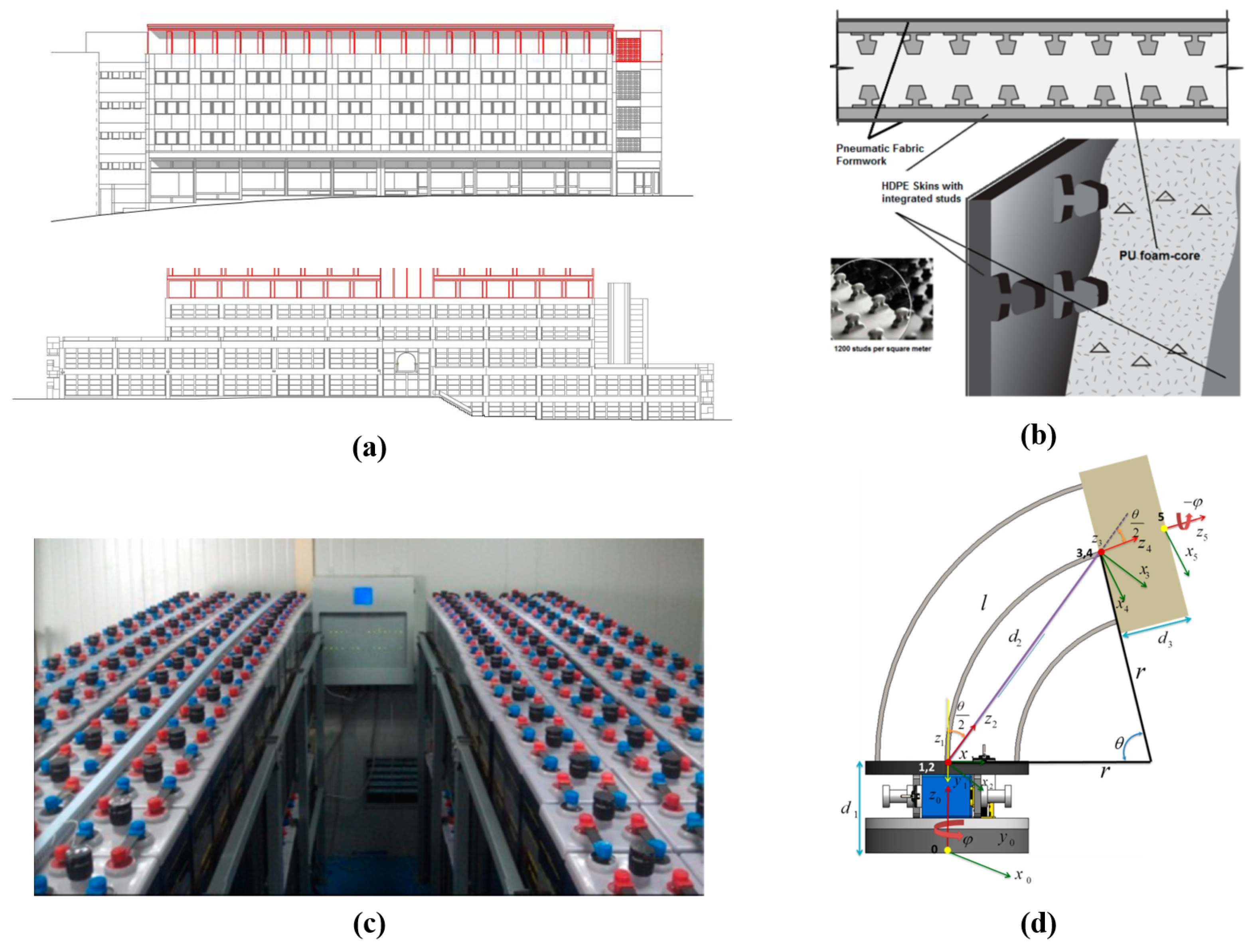
The informed designer can make use of these relationships and the strengths of additive manufacturing processes during the design stage. In addition to increasing the system reliability and reducing the part count in some systems, considering design-for-AM (DFAM) principles during design can drastically expand the available design space, as well as dodge many of the pitfalls encountered during the production stage. Preventing poor manufacturability of features, preventing material problems, and addressing other manufacturing concerns are a common theme for most design-for-manufacturing (DFM) methods [11,39]. When the system under design is a “modular” system which consists of a number of subsystems, this is particularly important. Expansion of the design space is very useful in ensuring that the resulting system can be optimized and rendered more reliable and useful to the stakeholders of the system. Some interesting practical examples of “modular” systems from several recently-published studies are shown in Figure 3. Figure 3a is a modular building addition system which can be used to add floors and rooms to existing buildings, presented by Dind et al. [40]; similarly, Sharafi et al. [41] designed a system of foam-filled modular building panels (Figure 3b) that can be used to rapidly put up new structures to be used by disaster victims. Electrical, power storage, and communications grids are also common users of modular systems, as discussed in the work by Zhang et al. [42] and shown in Figure 3c. Modular mechanical systems are common as well, such as the robotic manipulator (Figure 3d) described in the work by Mishra et al. [43].
Some unresolved issues exist within the DFAM paradigm, however, and restrict its applicability. First and foremost, during the design process, the practicability of actually using part consolidation or recombination in DFAM [5,6,7] must be carefully examined. This is not always a good approach for every system or product and this must be carefully considered when choosing to which design or re-design process to use [7,44]. Several previous studies have considered this question and have provided case studies and some guideline for using part consolidation or recombination effectively [5,6,7,44,45,46,47]; a more general set of guidelines for this is an important ongoing research topic. From the manufacturing perspective, AM processes tend to be at least as restrictive, if not more, in terms of manufacturability constraints than traditional processes. [29,48,49,50] The layer-based nature of all AM processes produce anisotropic material properties in the final parts [17,51,52,53], the surface finish of final parts can be poor [17,54,55,56], and the inherent residual stresses from some processes can dramatically reduce the fatigue life of the parts [57,58,59]. Due to these and other considerations, AM-made parts can be prone to fracture and may have poor dimensional accuracy for some processes and materials.
It should also be noted that not all materials can be effectively processed using AM, which adds a further consideration when using AM principles in design. Parts where more than one material is needed for correct functionality can be especially challenging to resolve under DFAM, as different types of materials generally need to be processed using different kinds of AM processes, which may have different levels of accuracy and material quality. Much progress has been made in all these areas, but they are important areas of concern during design when AM processes are involved. It is clear that using DFAM is a trade-off game for many systems, especially those requiring certification or which could cost human lives if they fail, and this needs to be carefully considered by designers considering the use of any DFAM method.
In the cases where AM is applicable and feasible to use in manufacturing the system and part consolidation or recombination are useful, the concepts of DFAM can be applied to modular systems; under this concept, components that were formerly designed as sub-assemblies can now be designed as single parts with many built-in functions, drastically decreasing the time and cost involved in designing, developing, integrating, and producing them. This definition of modular design by part consolidation was first described in detail by Hernandez et al. [60] in the context of rocket airframe design. The present study further explores and develops the concept for more general engineering design. The main focus of this study is to explore the idea of modular product design based on the use of large, complex, multi-function parts that can replace some sub-assemblies in modular design.
This study analyzes the concept in several sections, each presented in a section of the paper. First, an extensive review of the literature will be done to find the overall working definition of modular product design and explore traditional design modularization methods (Section 2. Next, AM-enabled design and combination-of-functions approach will be carefully defined and discussed (Section 3). The application space for the concept will also be discussed and a hybrid system proposed (Section 4). Finally, a case study to demonstrate the concept that will be developed in this study will be presented in detail and discussed (Section 5). Note that in this paper, the terms “system” and “product” are used interchangeably; in the context of this work, the only significant difference between two consists of the size and scale of the design.
2. Modular Design: Theory and Applications
The concept of modular design has been explored extensively, resulting in a wide variety of different definitions and problem-specific applications. Chung et al. [61] defined design modularity as the ability of a product to be producible via reconfiguration of existing parts or subsystems; another perspective, proposed by Gershenson et al. [62] and Baldwin et al. [63] is to intentionally design the system as a set of separable modules specific to that system or product. These definitions vary in their approach, but they both agree that the degree of modularity of a system is its ability to be separated and reconfigured. According to Bonvoisin et al. [64], modular design can be broken down into three complementary activities: (1) design with modules; (2) identification of modules; and (3) design of modules (Table 1). Concepts of “modularity” in design theory and practice have undergone several modifications in recent decades; according to an extensive literature survey conducted by Gershenson et al. [62], it is difficult to achieve a common consensus on definition and appropriate application of the terms modular or modularity. Similarly, Bonvoisin et al. [64] conclude that different researchers typically use their own interpretation of the definition and parameters used to produce modular designs, making a universal definition even more difficult to achieve. According to Todorova and Durisin [65], theories on modular management of products are often conflicted between increasing flexibility through manufacturing multiple products from few components and gaining flexibility through faster component innovation.
Even with this ambiguity in definitions, the interest in modularization of product design has increased over the years because of its many benefits in some applications. Gershenson et al. [62] and Ulrich and Tung [66] studied the impact of modularity on different industries. These studies described several benefits, including:
- Decrease in production cost due to re-usability of components across different families
- Ease of product updating due to functional modules
- Increased product variety from a smaller set of components
- Decreased order lead-time due to fewer different components
- Ease of design and testing due to the decoupling of product functions
- Ease of service due to differential consumption
Gershenson et al. [62] further concluded that, because of fewer assembly types and increase utilization of part designs for several systems, production quantities for a given module can be increased, while simultaneously reducing the learning curve for production personnel. In addition, because of fewer unique parts, products can be produced in greater quantity, decreasing the production cost. The development and production cost of modular components is strongly influenced by the product architecture and optimization status. It has been suggested in recent studies that increases in modularity of designs empowers environmental friendly end-of-life design and strategy planning. Ozman [67] studied the impact on open innovation, concluding that modularity increases incentive for open innovation during final stages of the design to make it compatible with different modules. However, Ettlie and Kubarek [68] studied commercial design teams to understand the extent to which the modularity is beneficial; after closely surveying 42 companies, they concluded that novelty in design suffers after 33% of design reuse, and further innovation was absent above 55%. Kassai et al. [69] studied the impact of modularity on agile manufacturing, during which the development of a modularity matrix helped designers to better understand the product.
Based on the definition and desired impact of modularity, researchers have defined several sets of parameters that drive modularity. Ericsson and Erixon [70] defined a modular driver as the driving forces that impact product modularity and competitive advantages gained from using it. Through different case studies, they obtained twelve modular drivers, which cover the entire life cycle. Kreng and Lee [71] also studied this problem and identified fourteen drivers based on strategies of modular design, product market characteristics, competitive advantages, and customer requirements. Okudan et al. [72,73] categorized the methods developed for planning and using product modularization in design into three broad categories, specifically: (1) data-mining approaches; (2) mathematical approaches; and (3) design-for-X approaches.
The data mining approaches analyze information from databases and surveys concerning the functions, geometry, supply chain information, and customer feedback to come up with new designs. Agard and Kusiak [74] described a data-mining approach for modularity analysis, which defines product modules by creating function structures that define the variability and generates options to satisfy design requirements. This approach helps to bridge gap between market and designers. However, data collection may take a long time and incur high cost for the stakeholders. Some researchers also proposed reverse engineering to modify existing products using adaptive redesign as part of a data mining approach [75,76,77]. The mathematical modeling approach involves designing for a set of constraints and objective functions using defined variables. In this method, a design structure matrix is commonly used to represent relationships between components and objectives [78,79,80]. These methods are useful during product development and product planning while considering many factors. Design-for-X considers conditions for multiple views such as assembly, sustainability, and life cycle [81,82,83]. Typically, the X factor that is designed for is a set of defined characteristics, or even a single characteristic. It differs from typical mathematical approaches as it focuses the bulk of design resources on the optimization of a single characteristic or a small set of them. Design-for-X approaches can also be used to generate design constraints to be used for a mathematical approach to designing the system [29].
A methodology for defining modules for lifecycle engineering using an interaction matrix in weighted average sense, and using algorithms for clustering the modules was developed by Gu et al. [84]. Similarly, Ma et al. [85] developed an approach using characteristics such as cost, environmental impact, and labor time to assess the sustainability at early design stage using fuzzy algorithm. They also included end of lifecycle stage uncertainty to assess the environmental impact. Mutingi et al. [86] also proposed application of a multi criteria fuzzy grouping genetic algorithm approach during early design stage when exact evaluation criteria are unknown to model imprecise information and evaluate possible solutions. Chung et al. [61] and Kristianto and Helo [87] studied the performance of the modular structure during various stages of the supply chain, and using statistical techniques concluded that modular structure optimization can reduce the environmental impact during different stages. Yang et al. [88] and Wang et al. [89] proposed eco-design methods for life cycle engineering of electronic and electricity equipment for improving maintainability, reusability and recyclability of equipment.
Based on the review of the literature discussed in this section, a basic modular design concept relevant to practical design-for-manufacturability problems can be generated. In this paradigm, the modularization of a product or system is a design method where the system is divided into well-defined units; ideally, these units can be designed and manufactured independently from each other and then integrated together by the design teams or a dedicated team of systems engineers; a secondary goal is often to use each unit in more than one product. The overall goal is to produce more product flexibility, increase design and manufacturing efficiency, overcome manufacturing problems, improve customer usability, and decrease overall product cost [20,60,84,90]. A number of generic principles can be derived to best use and harvest value from the modular design process [60,91,92]:
- Design of parts and subsystems should be done by specialized teams of experts
- After design, an integration phase will be required for the system, during which the parts and sub-assemblies are converted into a usable system or product
- Every aspect of the system should be standardized as much as possible
- Every design technique used or derived should be developed to be as widely applicable as possible
- Integrate further plans for testing, maintenance, and upgrades into the original design process
- Consider end-of-life disassembly, recycling, and retirement during the design process
- Every component and subsystem should be easily upgradable and repairable
- Systems should be easily reconfigurable for as many missions as possible
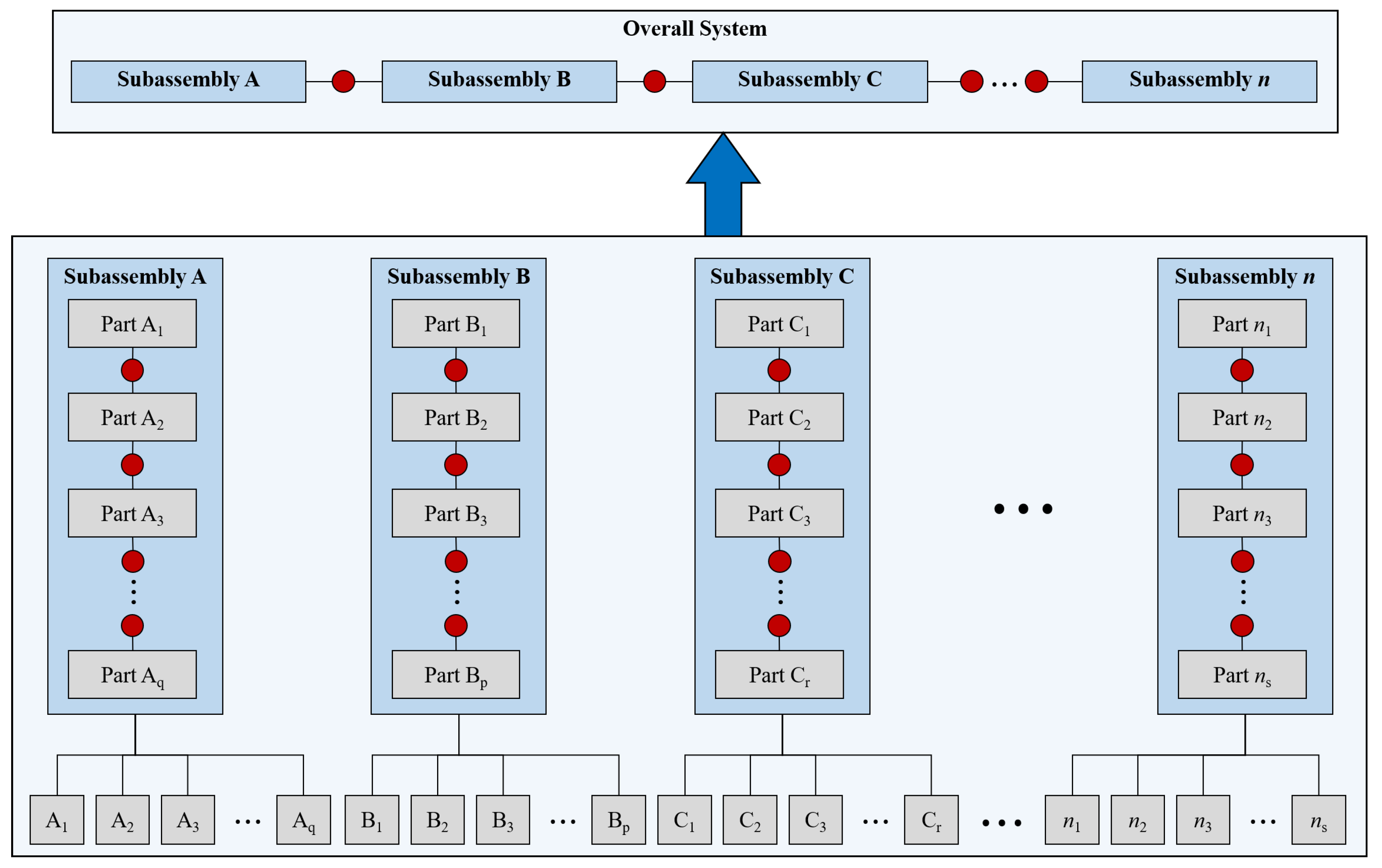
In traditional modular product design, these principles have been best achieved by designing and building a series of independent sub-systems, each with its own mission and functionality; the sum of these subsystems constitutes the overall system or product. This concept is shown in Figure 4, where the circular connectors represent interfaces for n sub-assemblies, each with a number () of parts for a total of parts. While this method is widely used in practice [64,70], it is not without its disadvantages. The main issue is the problems that naturally arise from the need to integrate the subsystems together, presumably made by different teams of designers [92]. Communication between these subsystems is key, but is not always effective due to integration issues and subsystem incompatibility. It is well known that most system reliability issues and errors occur at the interfaces within the system [32,93,94,95]. In order to effectively use modular design techniques in practice, a robust method of integration is needed, as discussed in the modular design literature above. The most effective systems engineering (SE) product lifecycle engines consider this in depth in their procedures. Sophisticated examples of this are the SE Engine used by the United States (US) National Aeronautics and Space Administration (NASA) [96] and System-of-Systems method used by the US Missile Defense Agency (MDA) [97].
3. AM-Enabled Modular Design (AMEMD) Concept
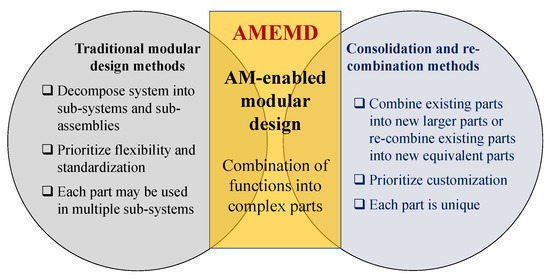
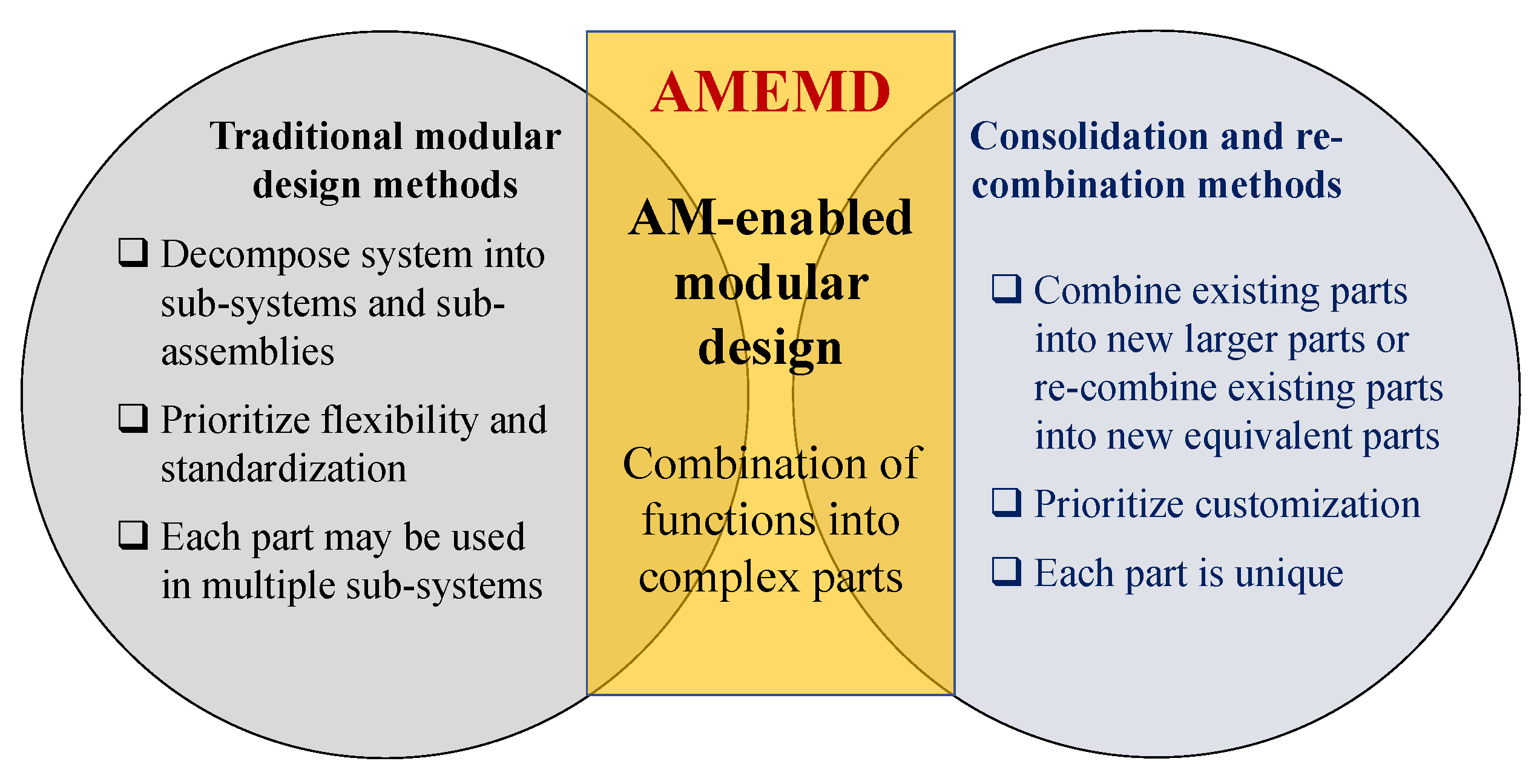
An effective, though not widely considered, method for modular or semi-modular design is enabled by AM technologies [4,60,98]. The ability of AM to make parts of almost unlimited complexity and with high functionality is the key [39,98]. The concept is simple: when possible, replace the subsystems within the overall system with complex parts that each have the functionality of a subsystem [60]. The benefits of modular design can still be realized, but with many fewer system interfaces and with a simpler design process. In theory, just the elimination of interfaces would dramatically improve the reliability of the system [95]. Figure 5 demonstrates the combination-of-functions concept. In the lower field, the functions are combined into a series of complex, multi-function parts which are essentially “functional modules” [60,99,100]; these are single parts but have the behavior of a sub-assembly of several parts, simply with the interfaces removed. When these are combined into the overall system, they still need to be integrated (where the red dots indicated integration points) but there are far fewer of these points than in the traditional system.
On engineering grounds, the potential objection to this approach in design is that the technique eliminates standardization and requires that the parts be highly specialized. Fortunately, one of the most important aspects of AM is its ability for easy mass customization for parts [101,102]. Since no special tooling or fixtures are required, batches of parts can be nearly infinitely customizable at the design stage [17]. If applied correctly by a knowledgeable designer, considering both the strengths and weaknesses of AM technologies, the need for a supply chain of standard off-the-shelf parts is greatly reduced or eliminated in many systems [17,24,26,28,103].
While some systems are practical to additively manufacture as a single part themselves, this effectively suppresses some of the main benefits of modular design. In particular, it is impossible to produce systems that are easily reconfigurable or reparable without replacing any major parts. It is also much more difficult to repair or maintain such systems or use them for purposes other than their core missions. When systems are built as a single part, they are usually throw-away products that are not meant to be repaired or reconfigured [60,104,105]. For most products that would benefit from modularity in design, the subsystem-level is likely the highest where it is practical to use a combination-of-functions approach. Hence the concept of feature cataloging in design [60,106], which uses a function database of options in design instead of a parts or subsystem catalog, as was often done in traditional design [107,108,109,110].
AM parts are, by definition, unique one-off or batch parts, where the cost of production depends only on the volume of material used, printing time, and post-processing requirements, as well as certification if needed. In functionally-modular systems, maintaining flexibility is paramount; AM is the perfect tool to deal with this, as the layered nature of additive manufacturing allows for almost infinite design flexibility during the design stage and allows easy part consolidation [4,60]. However, AM can limit modifications to the design in the field when compared with traditional modular design. From this perspective, it becomes clear that the use of AM in modular design requires the input of some non-modular design principles as well. Several of the basic modularization principles discussed in Section 2 are affected by this change in perspective, particularly standardization, serviceability, and customization (Table 2).
With these aspects in mind, both positive and negative, of the concept in mind, a reasonable definition of AM-enabled modular design (AMEMD) is:
Specific characteristics of this design methodology are:The process of decomposing a system into sets of functionalities or functions which can be performed by the design and additive manufacturing of multi-functional complex parts. These complex parts will be integrated together to produce the whole system. The functionality of the new system must be equal or superior to a system built from sub-assemblies of off-the-shelf parts, while containing fewer physical parts and interfaces.
- Complexity vs standardization: An increase in geometric complexity that results in fewer, but more function-dense parts is preferred over standardization of the parts and the use of assemblies of simple parts
- Optimization: Optimization for performance of complex parts is preferred over standardization
- Design and integration: Design teams for each of the complex parts focus on the design optimization and integration of the part into the system or product
- Design prototyping: System design prototypes can be produced quickly using AM technologies, aiding design and integration efforts
- On-demand manufacturing: For relatively simple systems, all AM parts, both original and replacement or upgrade parts, are manufactured on-demand directly from CAD data and are not kept in stock. For parts that belong to systems with certification requirements or that require constant stand-by spares, batches of parts can be made and kept as spares, with the option to make more on-demand if needed.
- Serviceability: While the parts are usually non-serviceable, they are easily replaced or upgraded, as long as the system allows access to the parts after completion (i.e., a “line-replaceable unit”)
- Part disposal: Old parts that are worn out or upgraded are easily recycled due to the low-hazard status of most AM-processes materials
- User customization: Parts of the system are almost infinitely customizable and optimizable during the design, but usually not customizable in the field after production
- Mass customization: Several parts can be made at once using the same machine and the same batch of raw materials; there may be several of the same part or several different parts in a batch
- Core mission: There is only one core mission or set of missions for each system configuration, but this is offset by the increased speed and reduced cost of production and by the optimization of the design before use
4. Domain Applicability
The method presented is not be universally applicable to all types of products and systems and would require a defined domain of validity. The most important restrictions on the use of this design methodology are the physical size of parts, the available batch sizes, material requirements, and the designer’s level of skill and experience with the technologies. In addition to these concerns, the designer must also ensure that the proper design-for-manufacturability constraints [29] are applied on the design to ensure that it is feasible for AM. Not all parts and systems will be best made using AM; this determination should be made early in the design process and the AMEMD only used if the complex parts can be feasibly made using AM. As discussed in the introduction, the practicality of using any DFAM method is dependent on the satisfaction of basic manufacturability constraints and the design considerations.
The three fundamental manufacturing aspects of all AM processes are the state of the raw material, the method of producing layers of raw material, and the process for fusing the layers together [17,18,27,29]. From these, the basic manufacturability constraints can be derived for a particular process; there are seven basic process, defined by these aspects, and each have their own set of constraints. Before any design can commence that may use AM, it should be ensured by the designer that the constraints can be met, since AM will not be a feasible manufacturing method otherwise and DFAM is not applicable.
For the combination-of-functions approach presented in this paper, the most important design consideration is the feasibility of consolidating or re-combining the basic parts or functions of the system. In cases where the design is new and the designer simply wishes to design several functions into one part, this is typically not a problem as the design can consider DFAM from conception. However, this method is likely most applicable to the re-design of systems which may benefit from the use of larger and more complex parts to replace subsystems. Therefore, the domain restriction on the design would be driven by the part consolidation. The primary issues that have come up in the literature [5,7,44,106,111,112] concerning part consolidation or re-combination are in the areas of repair, maintenance, and component upgrades to the system. As discussed in the previous section, the difficulty in these three areas is inherent in AM-made parts and is not unique to consolidated or re-combined parts. AM parts are typically not easily repairable, with the exception of some metal parts which can be welded or otherwise repaired using traditional manufacturing methods. Maintenance may or may not be a serious issue with AM parts, depending on the material being used and the function of the part; for example, some sintered metal parts subjected to wear can be left only partially dense and infused with oil to prevent the need for active maintenance. On the other hand, parts made from plastics, ceramics, and some metals cannot be maintained easily and so must usually be replaced when needed. One of the important advantages of using general modular design is the ability to upgrade sub-assemblies and individual parts on demand; this advantage does not typically exist at all for AM parts and this must be considered by designers.
In terms of the three main areas of concern for manufacturing constraints and three for part consolidation/re-combination, as well as the “practical” considerations described above, the potential drawbacks can be mitigated by careful planning and evaluation early in the design. Only from careful analysis of these constraints can the domain applicability be established for a particular design. Figure 6 shows some of the main decision variables that must be considered for this set of considerations. Under each are some of the possible aspects or requirements for the system that need to be identified or defined in order to best evaluate the benefits or drawbacks of DFAM; note that this is not an exhaustive list and other considerations may be needed for large and complex projects. The earlier in the design phase that DFAM can be considered, the better. Early adoption can serve to both drive the design or re-design to ensure feasibility with AM and to provide an early (and less costly) exit and adoption of another design method if it should become clear that the AM is not the best choice for manufacturing the system.
In cases where the use of AMEMD is applicable for part of the system or product but not all, a hybrid system could also certainly be developed, as shown in Figure 7. In practice, the hybrid system would be more applicable, as the system components or sub-assemblies could be made using the most feasible method for the design. Before using this or any other design methodology, the designer should carefully complete a manufacturability analysis to ensure that no dead-ends are encountered when completing the design. This is especially important when the product or system being designed will be used in a dynamic system or otherwise pose a risk to human life if failure occurs during use. This is an area that has not yet been explored well in the design literature and merits further consideration in future research in this area.
5. Case Study: Re-Design of AIM-120 AMRAAM Airframe
5.1. Overview and Model Details
Presented in this section is a simple case study that was developed to demonstrate the procedure of re-design using AMEMD principles. In this case study, the system was taken and the parts combined into as few parts as possible in order to reduce their number and to reduce interfaces. The parts were then optimized on performance and mass to produce a system that is both optimized and has fewer components. One of the case studies presented by Hernandez et al. [60] was a fixed-fin model of an AIM-9X Sidewinder (Air Intercept Missile 9X). In the present work, another (more complex) missile airframe was studied, the AIM-120 AMRAAM (Advanced Medium-Range Air-to-Air Missile) (Figure 8); the airframe for this missile can be re-designed in order to decrease the number of parts while not fundamentally changing the external design. However, the internal design can be modified to utilize lattice structures or topology optimization that can be made using AM to optimize the design. Note that the exact design for this airframe is not available due to commercial and government protection, so the one presented here is a simplified model [113,114,115,116] but is as accurate as possible and will serve the purpose of this study.
Table 3 shows the basic list of components for this model, which consists of tube sections, control surfaces, and fasteners, for a total of 17 major parts and 60 fasteners; the exploded view of the airframe is shown in Figure 9. In this model, the airframe parts are assumed to be made from tough polymer materials, such as a phenolic, except for the fasteners and the rear control surfaces; those parts are assumed to be made from aluminum. The walls of the airframe are assumed to be 4 mm thick. The airframe will be subjected to some fatigue, but the duration of that fatigue will be limited to the few hours that the missile will be attached to an aircraft and be in flight after launch. Therefore, the anisotropic nature of the AM materials is not anticipated to be a threat to the integrity of the structure during storage or use. In use, certification will be required, as it will be for all AM-build flight hardware.
Both phenolic materials [118,119] and aluminum [120,121] are feasible to additively manufacture using the choice of one of several processes, and all of the parts are small enough to produce using existing AM processes. Therefore, this airframe can be made within the AM manufacturability constraints and therefore is a good candidate for AMEMD to improve its design and reduce the number of parts. In reviewing the basic design of this system, it becomes clear that a hybrid modular-AMEMD method would produce the most effective design since some of the sub-systems have moving parts and need to stay intact. Some of the sub-assemblies (Table 4) need to remain as such, but re-design can be accomplished on some other areas. The particular areas that should be examined are those where large parts can be combined or an interface between several parts needs to be used.
5.2. Examination of Part Combination Opportunities
Excluding the fasteners, there are 17 interfaces in the model as it is currently designed, each of which should be examined to find opportunities to combine parts into larger and more complex ones:
- Nose cone—upper electronics housing: The nose cone holds the guidance for the missile and may need to be replaced or upgraded, so it is best to not eliminate this interface.
- Upper and lower electronics housing: One of the details that can be derived from the promotional literature for the AIM-120 is that the upper section which holds the electronics is made in two pieces, which can be easily combined into a single piece, assuming that the internal components will allow this. It is assumed that it was originally made in two parts to allow customized connections to the internal parts; using AM to create an optimized internal structure to connect to the electronics should allow the combination of these two parts. In addition to removing an interface, 12 of the fasteners can also be eliminated. Preserving access to the electronics for assembly and maintenance would be an important design consideration during the part re-combination. This should be checked to ensure that either no conflict exists or the AM part can be modified to account for it.
- Electronics housing to payload: It is obvious that the payload section needs to be easily accessible to the user of the missile, so it would be best to retain this interface as-is.
- Payload to upper control surfaces: For this missile, the upper control surfaces are fixed to the airframe and assumed to be made from the same material as the airframe. Therefore, the upper control surfaces can and should be integrated into the payload housing. The front fins could be combined with either the payload section or the motor/fuel section, but the best choice is the payload section; this is primarily to ensure that the air flows smoothly around the fins and that interface issues will not affect the leading surface of the control fin.
- Payload to motor/fuel section: As previously stated, the payload section should be independent as much as possible, so this interface should remain. Access to the motor and fuel supply are also reasons to retain the interface between the payload and motor/fuel sections.
- Motor to nozzle section: The rear control surfaces are driven by actuators near the nozzle and the nozzle and motor interface may need to be maintained and inspected.
- Nozzle section to rear control surface hinges: Since the hinges need to be free-moving and connected to internal actuators, no combination can be accomplished.
- Hinges to rear control surfaces: Since the rear control surfaces and hinges are both made from aluminum in this model, and their combination is relatively small, AMEMD makes sense for these parts.
5.3. Part Re-Combination and New System Model
After examination, three areas can benefit from the use of AMEMD; three sets of parts (the electronics housing, the mid-section fins and body, and the rear control surfaces) can be consolidated for a total reduction of parts from 17 to nine major components, plus the elimination of at least 12 fasteners. The upper and lower sections of the electronics housing (Figure 10a), the payload housing and its fins (Figure 10b), and the lower fins and their hinges (Figure 10c) can be recombined. In this case, the focus will be on reducing part count and optimizing the parts; future work will need to focus on other perspectives, such as ergonomics, safety, testing costs, and other such considerations.
The best design is certainly a hybrid of the AMEMD and the original design of the airframe, as shown in Figure 11. The nose cone and fuel/motor sections are left in their original design, the rear fins/hinges, the electronics housing, and the payload sections are combined to eliminate interfaces, and the rear housing section is a combination of both. Figure 12 shows the new airframe design, with the modified parts being highlighted in red; note the significant reduction of part count for the model with no fundamental change in the design.
5.4. Part Re-Design and Optimization
In addition to combining functions into larger and more complex parts, the parts under study can be further optimized due to the design freedom offered by the use of AM to manufacture them.
5.4.1. Electronics Housing Optimization
For the new electronics housing, the external design and interfaces between the payload and the nose cone are fixed. However, internal modifications can be made using AM-enabled methods, particularly topology optimization and lattice design. In addition to the basic housing, mounting bosses and other internal structures can be integrated into the design. Figure 13 shows examples of this for the section under study, where the Pareto® TopOpt software was used to optimize the part. The basic housing (Figure 13a) can be redesigned with a box lattice structure, reducing the mass significantly (about 40% for this section) while maintaining structural integrity. If integrated internal features are needed, such as mounting bosses for the electronics, these can be integrated into the lattice as well; Figure 13b shows this with a body-centered cubic (BCC) lattice design. Both of these designs can easily be made using a variety of AM processes, subject only to the minimal length scale requirement for manufacturing [122,123,124]. In addition to the reduction of mass, the use of a lattice structure could also assist in cooling the electronics system.
5.4.2. Payload and Upper Control Surfaces
In addition to the improvement of the internal structure, the payload section can also be integrated more fully with the control surfaces via a smoother transition. The smoother transition could reduce drag on the airframe, requiring less power to propel the missile; this, combined with the reduction in housing mass, increases the allowable payload mass and size without increasing the size of the missile or increasing fuel use. However, it is possible that other aspects could be negatively affected, such as frame integrity and stability during flight or the effect of a lighter airframe on the native sensor network in the missile.
Figure 14 shows an example solution for this, but many re-designs are feasible for this, determined primarily by the design and composition of the internal components. The fundamental purpose of the smoothing between the fins and the payload section is to reduce drag on the fins while also reinforcing them and preventing failure during flight. Since this missile is usually launched from a horizontal orientation, it is essential that the control surfaces are steady and reliable. The smoothing radius is a simple parameter that is easy to control during design and analysis, so two levels are shown. The radius can affect the streamlining of the missile, and therefore its stability and controllability during flight. Therefore, the designer should consider the best radius using both computational tools and physical testing.
5.4.3. Rear Control Surfaces
The re-design of the rear control surface is the least complex of the three new parts generated in this case study, requiring only the combination of the two parts and integrating. The combination of the two parts can be used as-is (Figure 15a) or the control surface can be re-designed to be more streamlined (Figure 15b), depending on the needs and preferences of the designer.
5.5. Design Evaluation
After re-design, the new system should be evaluated to ensure that the new design is at least equivalent to the old design; in theory, it should be superior to the old design but this must to be established in order to justify using AMEMD. Three major areas should be considered:
- Manufacturing: The manufacturing process for the system should have been improved, with a particular focus on reducing production time and cost. In this case, a number of parts were re-combined which may reduce the assembly time; however, it is possible that the assembly time would increase if the condensed parts required any special tools or new processes to integrate with the other parts. For the airframe re-design, this may be an issue for the electronics housing if the internal components of the missile require easy access. The designer should consider this a trade-off when it is a problem; this may be mitigated during the design by producing a new assembly procedure which considers integration with the larger housing section.
- Functionality and Performance: In order for AMEMD to be useful, it must produce some benefit to the designer. Therefore, it must be established that the new design gives at least one measurable benefit and that the general performance is at least as good as the old design. In this case, the performance and reliability of the missile must be at least as good as a missile which follows the original design. It was clear during the consolidation and optimization of the modified parts that the weight was certainly reduced, which may have a positive impact on performance and control. An additional advantage which may be gained from using AM is the presence of a layered surface if untreated; this may reduce drag on the airframe by providing a small surface roughness to reduce the laminar fluid flow around the airframe.
- Usability: In order for the new product or system to be useful, it must be reliable and useful for its core mission. The particular considerations for this and all AM-related designs are those discussed for the domain applicability, namely repairability, maintainability, and the possibility of upgrading the system. No matter how reliable the system is, there will eventually be breakdowns and needed part upgrades and so this must be considered during design. In terms of AM, repairability is sometimes possible but it should not be assumed for most AM parts. Maintainability and component upgrades are dependent on how the system is broken down; in general, any broken or worn parts made using AM would need to simply be replaced instead of being maintained or upgrades. However, this can be mitigated by the ability of AM to build complex and custom geometry and tailored materials, as this can reduce the need for maintenance. The on-demand manufacturability of AM parts would also reduce the need for part upgrades, as new part designs can be built as needed and the old one thrown away or recycled. For the missile airframe, the basic design is fairly well established, so it should be easy to design and manufacture new parts as needed in the field. Since the usability of the design is already established any upgrades or repairs would use a similar design to the old one, with similar reliability and usability.
6. Summary and Conclusions
The purpose of the present study was to explore the idea of using additive manufacturing to improve modular design of products by providing the means to use multi-function parts instead of sub-assemblies. Part consolidation and design modularity are often seen as conflicting design methods, but in the context of DFAM, they can be complementary for many systems. The elimination of the interfaces within the system is predicted to increase the reliability of the system, as well as simplifying it. The concept presented follows most of the basic principles of modular product design, as reviewed and discussed extensively, except for the principles of standardization, serviceability, and in-the-field customization. However, the loss of these capabilities within the modular design paradigm may not be a problem due to the design freedom from AM; standardization is no longer any more efficient than customization and serviceability and field customization are not major concerns, as new parts can be made on-demand in a few hours or days. This is, of course, subject to testing and certification requirements for any manufactured flight hardware made using AM. All AM processes have fairly restrictive manufacturability constraints, which must be considered carefully during design. In addition to the standard manufacturability constraints, the domain of applicability for this method is restricted by the size of the combined parts, the use of AM-processable materials, and on the skill and expertise of the designer to ensure manufacturability in the design. AM technologies are not efficient or preferable in all cases, so a study should be done before attempting such a design technique to ensure that it is feasible. The option to off-ramp from using an AM-based method should be built in as well, in case the design process proved non-feasible or too expensive for the problem as hand. The three most important material considerations are the choice of materials, the presence of fatigue stresses in the system (due to the anisotropic nature of the materials), and the smallest feature in the built part.
A broad case study was presented to demonstrate the concepts and to provide a practical example of applicability. A missile airframe was re-designed in a hybrid function-combination and traditional modular design, which resulted in the reduction of almost 50% of the parts and elimination of a number of fasteners. Optimization of the parts via AM-enabled digital means was demonstrated as well with the lattice design and streamlining of the parts.
This method is potentially very valuable for some systems, but should be considered one of several feasible methods until established as preferable and feasible by the designer. An important future research area for this concept is the certification of the resulting parts for use on actual systems. The case study presented in this study will require flight-hardware certification before use, but not all systems will require such a detailed and expensive process before use. For most simple systems and many others, this method may provide a more efficient design or re-design process which takes advantage of both the strengths of modularization and the design freedom of AM.
Author Contributions
C.C. and A.E.P. conceived and designed the study, C.C. preformed the modular design review, A.E.P. created the figures and case study, and A.E.P. and K.A.C. did the AM review and outline. C.L.C. and K.A.C. provided significant technical guidance and feedback on the ideas. All authors contributed to writing and polishing the manuscript for publication.
Funding
This research received no external funding
Acknowledgments
The authors would like to thank the following people for providing discussion and support for this work: James T. Allison, Dilcu Barnes, Paul D. Collopy, Kai James. Thanks to Kavian Niazi for granting permission to use the AIM-120 AMRAAM model from GrabCAD for the case study. The authors also thank the journal referees for their valuable feedback.
Conflicts of Interest
The authors declare no conflict of interest. No external funding was used to perform the work described in this study. Opinions and conclusions presented in this work are solely those of the authors.
References
- Rosen, D.W. Computer-Aided Design for Additive Manufacturing of Cellular Structures. Comput.-Aided Des. Appl. 2007, 4, 585–594. [Google Scholar] [CrossRef]
- Parthasarathy, J.; Starly, B.; Raman, S. A design for the additive manufacture of functionally graded porous structures with tailored mechanical properties for biomedical applications. J. Manuf. Process. 2011, 13, 160–170. [Google Scholar] [CrossRef]
- Doubrovski, Z.; Verlinden, J.C.; Geraedts, J.M.P. Optimal Design for Additive Manufacturing: Opportunities and Challenges. In Volume 9: 23rd International Conference on Design Theory and Methodology; 16th Design for Manufacturing and the Life Cycle Conference; ASME: New York City, NY, USA, 2011. [Google Scholar] [CrossRef]
- Yang, S.; Zhao, Y.F. Additive manufacturing-enabled design theory and methodology: A critical review. Int. J. Adv. Manuf. Technol. 2015, 80, 327–342. [Google Scholar] [CrossRef]
- Schmelzle, J.; Kline, E.V.; Dickman, C.J.; Reutzel, E.W.; Jones, G.; Simpson, T.W. (Re)Designing for Part Consolidation: Understanding the Challenges of Metal Additive Manufacturing. J. Mech. Des. 2015, 137, 111404. [Google Scholar] [CrossRef]
- Yang, S.; Santoro, F.; Sulthan, M.A.; Zhao, Y.F. A numerical-based part consolidation candidate detection approach with modularization considerations. Res. Eng. Des. 2018. [Google Scholar] [CrossRef]
- Oh, Y.; Zhou, C.; Behdad, S. Part decomposition and assembly-based (Re) design for additive manufacturing: A review. Addit. Manuf. 2018, 22, 230–242. [Google Scholar] [CrossRef]
- Yang, S.; Tang, Y.; Zhao, Y.F. A new part consolidation method to embrace the design freedom of additive manufacturing. J. Manuf. Process. 2015, 20, 444–449. [Google Scholar] [CrossRef]
- Jayal, A.; Badurdeen, F.; Dillon, O.; Jawahir, I. Sustainable manufacturing: Modeling and optimization challenges at the product, process and system levels. CIRP J. Manuf. Sci. Technol. 2010, 2, 144–152. [Google Scholar] [CrossRef]
- Susman, G. Integrating Design and Manufacturing for Competitive Advantage; Oxford University Press: Oxford, UK, 1992. [Google Scholar]
- Bralla, J.G. Design for Manufacturability Handbook; McGraw-Hill Education: New York City, NY, USA, 1998. [Google Scholar]
- Gu, D.D.; Meiners, W.; Wissenbach, K.; Poprawe, R. Laser additive manufacturing of metallic components: Materials, processes and mechanisms. Int. Mater. Rev. 2012, 57, 133–164. [Google Scholar] [CrossRef]
- Chan, K.S.; Koike, M.; Mason, R.L.; Okabe, T. Fatigue Life of Titanium Alloys Fabricated by Additive Layer Manufacturing Techniques for Dental Implants. Metall. Mater. Trans. A 2012, 44, 1010–1022. [Google Scholar] [CrossRef]
- Jardini, A.L.; Larosa, M.A.; de Carvalho Zavaglia, C.A.; Bernardes, L.F.; Lambert, C.S.; Kharmandayan, P.; Calderoni, D.; Filho, R.M. Customised titanium implant fabricated in additive manufacturing for craniomaxillofacial surgery. Virtual Phys. Prototyp. 2014, 9, 115–125. [Google Scholar] [CrossRef]
- Salmi, M.; Tuomi, J.; Paloheimo, K.S.; Björkstrand, R.; Paloheimo, M.; Salo, J.; Kontio, R.; Mesimäki, K.; Mäkitie, A.A. Patient-specific reconstruction with 3D modeling and DMLS additive manufacturing. Rapid Prototyp. J. 2012, 18, 209–214. [Google Scholar] [CrossRef]
- Akmal, J.; Salmi, M.; Mäkitie, A.; Björkstrand, R.; Partanen, J. Implementation of Industrial Additive Manufacturing: Intelligent Implants and Drug Delivery Systems. J. Funct. Biomater. 2018, 9, 41. [Google Scholar] [CrossRef] [PubMed]
- Guo, N.; Leu, M.C. Additive manufacturing: Technology, applications and research needs. Front. Mech. Eng. 2013, 8, 215–243. [Google Scholar] [CrossRef]
- Gibson, I.; Rosen, D.; Stucker, B. Additive Manufacturing Technologies: 3D Printing, Rapid Prototyping, and Direct Digital Manufacturing; Springer: Berlin, Germany, 2016. [Google Scholar]
- Lei, N.; Yao, X.; Moon, S.K.; Bi, G. An additive manufacturing process model for product family design. J. Eng. Des. 2016, 27, 751–767. [Google Scholar] [CrossRef]
- Agard, B.; Bassetto, S. Modular design of product families for quality and cost. Int. J. Prod. Res. 2013, 51, 1648–1667. [Google Scholar] [CrossRef]
- Jiao, J.R.; Simpson, T.W.; Siddique, Z. Product family design and platform-based product development: A state-of-the-art review. J. Intell. Manuf. 2007, 18, 5–29. [Google Scholar] [CrossRef]
- Nayak, R.U.; Chen, W.; Simpson, T.W. A Variation-Based Method for Product Family Design. Eng. Optim. 2002, 34, 65–81. [Google Scholar] [CrossRef] [Green Version]
- Gonzalez-Zugasti, J.P.; Otto, K.N.; Baker, J.D. Assessing value in platformed product family design. Res. Eng. Des. 2001, 13, 30–41. [Google Scholar] [CrossRef]
- Patterson, A.E.; Thomas, L.D.; Messimer, S.L. Disruptive Effects of Additive Technologies on SE Product Lifecycle. Procedings of the JANNAF Technical Interchange Conference, Huntsville, AL, USA, 23–25 August 2016. [Google Scholar] [CrossRef]
- Liu, P.; Huang, S.H.; Mokasdar, A.; Zhou, H.; Hou, L. The impact of additive manufacturing in the aircraft spare parts supply chain: Supply chain operation reference (SCOR) model based analysis. Prod. Plan. Control 2013, 25, 1169–1181. [Google Scholar] [CrossRef]
- Khajavi, S.H.; Partanen, J.; Holmström, J. Additive manufacturing in the spare parts supply chain. Comput. Ind. 2014, 65, 50–63. [Google Scholar] [CrossRef]
- ASTM. F2792-12a: Standard Terminology for Additive Manufacturing Technologies. ASTM Stand. 2012. [Google Scholar] [CrossRef]
- Patterson, A.E.; Collopy, P.; Messimer, S.L. State-of-the-Art Survey of Additive Manufacturing Technologies, Methods, and Materials; Technical Report, Report Number UAH 2015-06; Department of Industrial & Systems Engineering and Engineering Management, University of Alabama in Huntsville: Huntsville, IL, USA, 2015. [Google Scholar] [CrossRef]
- Patterson, A.E.; Allison, J.T. Manufacturability Constraint Formulation for Design Under Hybrid Additive-Subtractive Manufacturing. In ASME 2018 IDETC/CIE: 23rd Deign for Manufacturing and the Life Cycle Conference (DFMLC); ASME: Quebec City, QC, Canada, 2018. [Google Scholar] [CrossRef]
- Murthy, D.; Østerås, T.; Rausand, M. Component reliability specification. Reliab. Eng. Syst. Saf. 2009, 94, 1609–1617. [Google Scholar] [CrossRef]
- Aal, A.; Polte, T. On component reliability and system reliability for automotive applications. In Proceedings of the IEEE International Integrated Reliability Workshop Final Report, South Lake Tahoe, CA, USA, 14–18 October 2012. [Google Scholar] [CrossRef]
- Elsayed, E.A. Reliability Engineering (Wiley Series in Systems Engineering and Management); Wiley: Hoboken, NJ, USA, 2012. [Google Scholar]
- Hohenbichler, M.; Rackwitz, R. First-order concepts in system reliability. Struct. Saf. 1982, 1, 177–188. [Google Scholar] [CrossRef]
- Chern, M.S. On the computational complexity of reliability redundancy allocation in a series system. Oper. Res. Lett. 1992, 11, 309–315. [Google Scholar] [CrossRef]
- Frey, D.; Palladino, J.; Sullivan, J.; Atherton, M. Part count and design of robust systems. Syst. Eng. 2007, 10, 203–221. [Google Scholar] [CrossRef]
- ElMaraghy, W.; ElMaraghy, H.; Tomiyama, T.; Monostori, L. Complexity in engineering design and manufacturing. CIRP Ann. 2012, 61, 793–814. [Google Scholar] [CrossRef]
- Xu, Z.; Kuo, W.; Lin, H.H. Optimization limits in improving system reliability. IEEE Trans. Reliab. 1990, 39, 51–60. [Google Scholar] [CrossRef]
- Billinton, R.; Allan, R.N. Reliability Evaluation of Engineering Systems; Springer: Berlin, Germany, 1983. [Google Scholar]
- Anderson, K.B.; Lockwood, S.Y.; Martin, R.S.; Spence, D.M. A 3D Printed Fluidic Device that Enables Integrated Features. Anal. Chem. 2013, 85, 5622–5626. [Google Scholar] [CrossRef] [PubMed]
- Dind, A.; Lufkin, S.; Rey, E. A Modular Timber Construction System for the Sustainable Vertical Extension of Office Buildings. Designs 2018, 2, 30. [Google Scholar] [CrossRef]
- Sharafi, P.; Nemati, S.; Samali, B.; Ghodrat, M. Development of an Innovative Modular Foam-Filled Panelized System for Rapidly Assembled Postdisaster Housing. Buildings 2018, 8, 97. [Google Scholar] [CrossRef]
- Zhang, X.; Huang, Y.; Li, L.; Yeh, W.C. Power and Capacity Consensus Tracking of Distributed Battery Storage Systems in Modular Microgrids. Energies 2018, 11, 1439. [Google Scholar] [CrossRef]
- Mishra, A.; Mondini, A.; Dottore, E.D.; Sadeghi, A.; Tramacere, F.; Mazzolai, B. Modular Continuum Manipulator: Analysis and Characterization of Its Basic Module. Biomimetics 2018, 3, 3. [Google Scholar] [CrossRef]
- Demir, İ.; Aliaga, D.G.; Benes, B. Near-convex decomposition and layering for efficient 3D printing. Addit. Manuf. 2018, 21, 383–394. [Google Scholar] [CrossRef]
- Liu, J. Guidelines for AM part consolidation. Virtual Phys. Prototyp. 2016, 11, 133–141. [Google Scholar] [CrossRef]
- Yang, S.; Zhao, Y.F. Additive Manufacturing-Enabled Part Count Reduction: A Lifecycle Perspective. J. Mech. Des. 2018, 140, 031702. [Google Scholar] [CrossRef]
- Yang, S.; Zhao, Y. Conceptual design for assembly in the context of additive manufacturing. In Proceedings of the 26th Annual International Solid Freeform Fabrication Symposium, Austin, TX, USA, 10–12 August 2016. [Google Scholar]
- Thompson, M.K.; Moroni, G.; Vaneker, T.; Fadel, G.; Campbell, R.I.; Gibson, I.; Bernard, A.; Schulz, J.; Graf, P.; Ahuja, B.; et al. Design for Additive Manufacturing: Trends, opportunities, considerations, and constraints. CIRP Ann. 2016, 65, 737–760. [Google Scholar] [CrossRef] [Green Version]
- Mhapsekar, K.; McConaha, M.; Anand, S. Additive Manufacturing Constraints in Topology Optimization for Improved Manufacturability. J. Manuf. Sci. Eng. 2018, 140, 051017. [Google Scholar] [CrossRef]
- Meisel, N.; Williams, C. An Investigation of Key Design for Additive Manufacturing Constraints in Multimaterial Three-Dimensional Printing. J. Mech. Des. 2015, 137, 111406. [Google Scholar] [CrossRef]
- Kok, Y.; Tan, X.; Wang, P.; Nai, M.; Loh, N.; Liu, E.; Tor, S. Anisotropy and heterogeneity of microstructure and mechanical properties in metal additive manufacturing: A critical review. Mater. Des. 2018, 139, 565–586. [Google Scholar] [CrossRef]
- Popovich, A.A.; Sufiiarov, V.S.; Borisov, E.V.; Polozov, I.A.; Masaylo, D.V.; Grigoriev, A.V. Anisotropy of mechanical properties of products manufactured using selective laser melting of powdered materials. Russ. J. Non-Ferr. Met. 2017, 58, 389–395. [Google Scholar] [CrossRef]
- Ahn, S.H.; Montero, M.; Odell, D.; Roundy, S.; Wright, P.K. Anisotropic material properties of fused deposition modeling ABS. Rapid Prototyp. J. 2002, 8, 248–257. [Google Scholar] [CrossRef] [Green Version]
- Kaji, F.; Barari, A. Evaluation of the Surface Roughness of Additive Manufacturing Parts Based on the Modelling of Cusp Geometry. IFAC-PapersOnLine 2015, 48, 658–663. [Google Scholar] [CrossRef]
- Townsend, A.; Senin, N.; Blunt, L.; Leach, R.; Taylor, J. Surface texture metrology for metal additive manufacturing: A review. Precis. Eng. 2016, 46, 34–47. [Google Scholar] [CrossRef]
- Alfieri, V.; Argenio, P.; Caiazzo, F.; Sergi, V. Reduction of Surface Roughness by Means of Laser Processing over Additive Manufacturing Metal Parts. Materials 2016, 10, 30. [Google Scholar] [CrossRef] [PubMed]
- Patterson, A.E.; Messimer, S.L.; Farrington, P.A. Overhanging Features and the SLM/DMLS Residual Stresses Problem: Review and Future Research Need. Technologies 2017, 5, 15. [Google Scholar] [CrossRef]
- Mukherjee, T.; Zhang, W.; DebRoy, T. An improved prediction of residual stresses and distortion in additive manufacturing. Comput.l Mater. Sci. 2017, 126, 360–372. [Google Scholar] [CrossRef]
- Li, C.; Liu, Z.; Fang, X.; Guo, Y. Residual Stress in Metal Additive Manufacturing. Procedia CIRP 2018, 71, 348–353. [Google Scholar] [CrossRef]
- Hernandez, R.; Singh, H.; Messimer, S.; Patterson, A. Design and Performance of Modular 3-D Printed Solid-Propellant Rocket Airframes. Aerospace 2017, 4, 17. [Google Scholar] [CrossRef]
- Chung, W.H.; Kremer, G.E.O.; Wysk, R.A. Life cycle implications of product modular architectures in closed-loop supply chains. Int. J. Adv. Manuf. Technol. 2013, 70, 2013–2028. [Google Scholar] [CrossRef]
- Gershenson, J.K.; Prasad, G.J.; Zhang, Y. Product modularity: Definitions and benefits. J. Eng. Des. 2003, 14, 295–313. [Google Scholar] [CrossRef]
- Baldwin, C.; Clark, K. Managing in the Age of Modularity. Harvard Bus. Rev. 1997, 75, 84–93. [Google Scholar]
- Bonvoisin, J.; Halstenberg, F.; Buchert, T.; Stark, R. A systematic literature review on modular product design. J. Eng. Des. 2016, 27, 488–514. [Google Scholar] [CrossRef]
- Todorova, G.; Burisin, B. Do firms innovate through integrated modular designs? Disentangling the effects of types of modularity on types of innovation. In KITeS Knowledge, Internationalization, and Technology Studies; Technical Report; Bocconi University: Milan, Italy, 2009. [Google Scholar]
- Ulrich, K. Fundamentals of Product Modularity. In Management of Design; Springer: Berlin, Germany, 1994; pp. 219–231. [Google Scholar] [CrossRef]
- Ozman, M. Modularity, Industry Life Cycle and Open Innovation. J. Technol. Manag. Innovat. 2011, 6, 26–34. [Google Scholar] [CrossRef]
- Ettlie, J.E.; Kubarek, M. Design Reuse in Manufacturing and Services. J. Prod. Innovat. Manag. 2008, 25, 457–472. [Google Scholar] [CrossRef]
- Kassi, T.; Leisti, S.; Puheloinen, T. Impact of product modular design on agile manufacturing. Mechanika 2008, 74, 56–62. [Google Scholar]
- Ericsson, A.; Erixon, G. Controlling Design Variants: Modular Product Platforms; Society of Manufacturing Engineers: Dearborn, MI, USA, 1999. [Google Scholar]
- Kreng, V.B.; Lee, T.P. QFD-based modular product design with linear integer programming—A case study. J. Eng. Des. 2004, 15, 261–284. [Google Scholar] [CrossRef]
- Kremer, G.E.O.; Gupta, S. Analysis of modularity implementation methods from an assembly and variety viewpoints. Int. J. Adv. Manuf. Technol. 2012, 66, 1959–1976. [Google Scholar] [CrossRef]
- Okudan, G.E.; Chiu, M.C.; Kim, T.H. Perceived feature utility-based product family design: A mobile phone case study. J. Intell. Manuf. 2012, 24, 935–949. [Google Scholar] [CrossRef]
- Agard, B.; Kusiak, A. Data-mining-based methodology for the design of product families. Int. J. Prod. Res. 2004, 42, 2955–2969. [Google Scholar] [CrossRef]
- Otto, K.N.; Wood, K.L. Product Evolution: A Reverse Engineering and Redesign Methodology. Res. Eng. Des. 1998, 10, 226–243. [Google Scholar] [CrossRef]
- Stone, R.B.; McAdams, D.A.; Kayyalethekkel, V.J. A product architecture-based conceptual DFA technique. Des. Stud. 2004, 25, 301–325. [Google Scholar] [CrossRef]
- Asan, U.; Polat, S.; Serdar, S. An integrated method for designing modular products. J. Manuf. Technol. Manag. 2004, 15, 29–49. [Google Scholar] [CrossRef]
- Wasley, N.S.; Lewis, P.K.; Mattson, C.A.; Ottosson, H.J. Experimenting with concepts from modular product design and multi-objective optimization to benefit people living in poverty. Dev. Eng. 2017, 2, 29–37. [Google Scholar] [CrossRef]
- Yigit, A.S.; Ulsoy, A.G.; Allahverdi, A. Optimizing modular product design for reconfigurable manufacturing. J. Intell. Manuf. 2002, 13, 309–316. [Google Scholar] [CrossRef]
- Levin, M.S. Combinatorial optimization in system configuration design. Autom. Remote Control 2009, 70, 519–561. [Google Scholar] [CrossRef]
- Kuo, T.C.; Huang, S.H.; Zhang, H.C. Design for manufacture and design for ‘X’: Concepts, applications, and perspectives. Comput. Ind. Eng. 2001, 41, 241–260. [Google Scholar] [CrossRef]
- Gatenby, D.A.; Foo, G. Design for X (DFX): Key to Competitive, Profitable Products. AT&T Tech. J. 1990, 69, 2–13. [Google Scholar] [CrossRef]
- Chiu, M.C.; Okudan, G. An Integrative Methodology for Product and Supply Chain Design Decisions at the Product Design Stage. J. Mech. Des. 2011, 133, 021008. [Google Scholar] [CrossRef]
- Gu, P.; Hashemian, M.; Sosale, S.; Rivin, E. An Integrated Modular Design Methodology for Life-Cycle Engineering. CIRP Ann. 1997, 46, 71–74. [Google Scholar] [CrossRef]
- Ma, J.; Kremer, G.E.O. A sustainable modular product design approach with key components and uncertain end-of-life strategy consideration. Int. J. Adv. Manuf. Technol. 2015, 85, 741–763. [Google Scholar] [CrossRef]
- Mutingi, M.; Dube, P.; Mbohwa, C. A Modular Product Design Approach for Sustainable Manufacturing in A Fuzzy Environment. Procedia Manuf. 2017, 8, 471–478. [Google Scholar] [CrossRef]
- Kristianto, Y.; Helo, P. Product architecture modularity implications for operations economy of green supply chains. Transp. Res. Part E Logist. Transp. Rev. 2014, 70, 128–145. [Google Scholar] [CrossRef]
- Yang, Q.; Yu, S.; Sekhari, A. A modular eco-design method for life cycle engineering based on redesign risk control. Int. J. Adv. Manuf. Technol. 2011, 56, 1215–1233. [Google Scholar] [CrossRef]
- Wang, Q.; Tang, D.; Yin, L.; Yang, J. A Method for Green Modular Design Considering Product Platform Planning Strategy. Procedia CIRP 2016, 56, 40–45. [Google Scholar] [CrossRef]
- Booker, J.; Swift, K.; Brown, N. Designing for assembly quality: Strategies, guidelines and techniques. J. Eng. Des. 2005, 16, 279–295. [Google Scholar] [CrossRef]
- Gu, P.; Sosale, S. Product modularization for life cycle engineering. Robot. Comput.-Integr. Manuf. 1999, 15, 387–401. [Google Scholar] [CrossRef]
- Sosa, M.E.; Eppinger, S.D.; Rowles, C.M. Identifying Modular and Integrative Systems and Their Impact on Design Team Interactions. J. Mech. Des. 2003, 125, 240. [Google Scholar] [CrossRef]
- Li, Z.S.; Mobin, M.S. System reliability assessment incorporating interface and function failure. In Proceedings of the Annual Reliability and Maintainability Symposium (RAMS), Palm Harbor, FL, USA, 26–29 January 2015. [Google Scholar] [CrossRef]
- Ebeling, C.E. An Introduction to Reliability and Maintainability Engineering; Waveland Press: Long Grove, IL, USA, 2009. [Google Scholar]
- Blanchard, B.S.; Fabrycky, W.J. Systems Engineering and Analysis, 4th ed.; Prentice Hall: Upper Saddle River, NJ, USA, 2005. [Google Scholar]
- NASA. NASA Systems Engineering Handbook: NASA/Sp-2016-6105 Rev2 - Full Color Version; 12th Media Services: Suwanee, GA, USA, 2017. [Google Scholar]
- Sommerer, S.; Guevara, M.D.; Landis, M.A.; Rizzuto, J.M.; Sheppard, J.M.; Grant, C.J. System-of-Systems Engineering in Air and Missile Defense. Johns Hopkins APL Tech. Dig. 2012, 31, 5–20. [Google Scholar]
- Becker, R.; Grzesiak, A.; Henning, A. Rethink assembly design. Assem. Autom. 2005, 25, 262–266. [Google Scholar] [CrossRef]
- Salemi, B.; Moll, M.; Shen, W.-M. SUPERBOT: A Deployable, Multi-Functional, and Modular Self-Reconfigurable Robotic System. In Proceedings of the IEEE/RSJ International Conference on Intelligent Robots and Systems, Beijing, China, 9–15 October 2006. [Google Scholar] [CrossRef]
- Kelmar, L.; Khosla, P. Automatic generation of kinematics for a reconfigurable modular manipulator system. In Proceedings of the IEEE International Conference on Robotics and Automation, Philadelphia, PA, USA, 24–29 April 1988. [Google Scholar] [CrossRef]
- Berman, B. 3-D printing: The new industrial revolution. Bus. Horiz. 2012, 55, 155–162. [Google Scholar] [CrossRef]
- Petrick, I.J.; Simpson, T.W. 3D Printing Disrupts Manufacturing: How Economies of One Create New Rules of Competition. Res.-Technol. Manag. 2013, 56, 12–16. [Google Scholar] [CrossRef]
- Thomas, D. Costs, benefits, and adoption of additive manufacturing: A supply chain perspective. Int. J. Adv. Manuf. Technol. 2015, 85, 1857–1876. [Google Scholar] [CrossRef] [PubMed]
- Charter, M. Sustainable Product Design. In The Durable Use of Consumer Products; Springer: Berlin, Germany, 1998; pp. 57–68. [Google Scholar] [CrossRef]
- Allison, N.; Richards, J. Current status and future trends for disposable technology in the biopharmaceutical industry. J. Chem. Technol. Biotechnol. 2013, 89, 1283–1287. [Google Scholar] [CrossRef]
- Maidin, S.B.; Campbell, I.; Pei, E. Development of a design feature database to support design for additive manufacturing. Assem. Autom. 2012, 32, 235–244. [Google Scholar] [CrossRef] [Green Version]
- Boothroyd, G.; Knight, W. Design for assembly. IEEE Spectrum. 1993, 30, 53–55. [Google Scholar] [CrossRef]
- Mok, H.S.; Kim, C.H.; Kim, C.B. Automation of mold designs with the reuse of standard parts. Expert Syst. Appl. 2011, 38, 12537–12547. [Google Scholar] [CrossRef]
- Culley, S.J. Classification approaches for standard parts to aid design reuse. Proc. Inst. Mech. Eng. Part B J. Eng. Manuf. 1999, 213, 203–207. [Google Scholar] [CrossRef]
- Novak, S.; Eppinger, S.D. Sourcing By Design: Product Complexity and the Supply Chain. Manag. Sci. 2001, 47, 189–204. [Google Scholar] [CrossRef] [Green Version]
- Laverne, F.; Segonds, F.; Anwer, N.; Coq, M.L. Assembly Based Methods to Support Product Innovation in Design for Additive Manufacturing: An Exploratory Case Study. J. Mech. Des. 2015, 137, 121701. [Google Scholar] [CrossRef] [Green Version]
- Tang, Y.; Yang, S.; Zhao, Y.F. Sustainable Design for Additive Manufacturing Through Functionality Integration and Part Consolidation. In Handbook of Sustainability in Additive Manufacturing; Springer: Singapore, 2016; pp. 101–144. [Google Scholar] [CrossRef]
- Niazi, K. AIM-120 AMRAAM. GrabCAD Model. Available online: https://grabcad.com/library/aim-120-amraam-1 (accessed on 30 May 2018).
- Gonzalez-Sanchez, M.; Amezquita-Brooks, L.; Liceaga-Castro, E.; del C Zambrano-Robledo, P. Simplifying quadrotor controllers by using simplified design models. In Proceedings of the 52nd IEEE Conference on Decision and Control, Florence, Italy, 10–13 December 2013. [Google Scholar] [CrossRef]
- Kim, C.; Mijar, A.; Arora, J. Development of simplified models for design and optimization of automotive structures for crashworthiness. Struct. Multidiscip. Optim. 2001, 22, 307–321. [Google Scholar] [CrossRef]
- Lu, X.; Xie, L.; Yu, C.; Lu, X. Development and application of a simplified model for the design of a super-tall mega-braced frame-core tube building. Eng. Struct. 2016, 110, 116–126. [Google Scholar] [CrossRef] [Green Version]
- AMRAAM Missile: Modern, Versatile, and Proven. Available online: https://www.raytheon.com/capabilities/products/amraam (accessed on 15 June 2018).
- Snelling, D.; Williams, C.; Druschitz, A. A comparison of binder burnout and mechanical characteristics of printed and chemically bonded sand molds. In Proceedings of the 2014 Solid Freeform Fabrication Symposium, Austin, TX, USA, 13–15 August 2014. [Google Scholar]
- Kumar, S.; Kruth, J.P. Composites by rapid prototyping technology. Mater. Des. 2010, 31, 850–856. [Google Scholar] [CrossRef]
- Louvis, E.; Fox, P.; Sutcliffe, C.J. Selective laser melting of aluminium components. J. Mater. Process. Technol. 2011, 211, 275–284. [Google Scholar] [CrossRef]
- Aboulkhair, N.T.; Everitt, N.M.; Maskery, I.; Ashcroft, I.; Tuck, C. Selective laser melting of aluminum alloys. MRS Bull. 2017, 42, 311–319. [Google Scholar] [CrossRef] [Green Version]
- Vyatskikh, A.; Delalande, S.; Kudo, A.; Zhang, X.; Portela, C.M.; Greer, J.R. Additive manufacturing of 3D nano-architected metals. Nat. Commun. 2018, 9. [Google Scholar] [CrossRef] [PubMed]
- Chang, J.; He, J.; Mao, M.; Zhou, W.; Lei, Q.; Li, X.; Li, D.; Chua, C.K.; Zhao, X. Advanced Material Strategies for Next-Generation Additive Manufacturing. Materials 2018, 11, 166. [Google Scholar] [CrossRef] [PubMed]
- Slotwinski, J.A.; Garboczi, E.J.; Hebenstreit, K.M. Porosity Measurements and Analysis for Metal Additive Manufacturing Process Control. J. Res. Nat. Inst. Stand. Technol. 2014, 119, 494. [Google Scholar] [CrossRef] [PubMed]
Figure 1.
AM concept map.

Figure 2.
System reliabilities and interfaces concept.

Figure 3.
Modular design examples: (a) design method to add sections to existing buildings [40]; (b) modular panels for emergency housing construction [41]; (c) battery storage system in an electric grid [42]; and (d) modular mechanical manipulator [43].

Figure 4.
Modular design complexity levels (adapted from [60]).
Figure 4.
Modular design complexity levels (adapted from [60]).


Figure 6.
Some aspects to consider when evaluating the feasibility of DFAM.

Figure 7.
Hybrid subassembly-AMEMD system design concept.


Figure 10.
Part recombination opportunities for the AIM-120 AMRAAM airframe, (a) electronics housing; (b) payload section and upper fins, and (c) rear fins and actuator hinges.
Figure 10.
Part recombination opportunities for the AIM-120 AMRAAM airframe, (a) electronics housing; (b) payload section and upper fins, and (c) rear fins and actuator hinges.

Figure 11.
Proposed new AMRAAM airframe system design.

Figure 12.
Proposed new AMRAAM airframe system design.

Figure 13.
Internal lattice designs for electronics housing section where (a) is a simple lattice and (b) is a BCC lattice with integrated mounting bosses.
Figure 13.
Internal lattice designs for electronics housing section where (a) is a simple lattice and (b) is a BCC lattice with integrated mounting bosses.

Figure 14.
Redesign of payload section and upper control surfaces, where both new designs use an internal lattice and (a) uses a corner smoothing of mm while (b) uses mm.
Figure 14.
Redesign of payload section and upper control surfaces, where both new designs use an internal lattice and (a) uses a corner smoothing of mm while (b) uses mm.

Figure 15.
Redesign of rear control surface, (a) with a simple integration of the two functions and (b) with a re-design to streamline the airflow around the fin.
Figure 15.
Redesign of rear control surface, (a) with a simple integration of the two functions and (b) with a re-design to streamline the airflow around the fin.


Table 1.
Basic modular design activities.
| Design with Modules | Involves designing a new product out of existing pools of pre-defined modules or parts; conceptually, this is similar to assembling a set of Lego-blocks |
| Identifying Modules | Requires a deep understanding of the product or system and includes studying the current product, evaluating the component grouping, clustering the components accordingly, then redesigning and integrating the defined modules and their interfaces |
| Design of Modules | Necessitates the design of new modules to meet new requirements or to replace obsolete or poorly-designed modules |
Table 2.
Modular principles directly affected by the combination-of-functions approach.
| Standardization | AM allows the standardization of components, but it is usually more efficient and effective to prioritize optimization of the parts over standardization. |
| Serviceability | Most AM parts do not allow service on the parts after they are built and must simply be replaced when they wear out. The AM materials are typically highly recyclable and may even be recycled and made into new raw material by the part manufacturer, drastically reducing costs and simplifying the supply chain. The great reduction in cost, both from the elimination of tooling and from recycled materials, could offset the disadvantages of using non-serviceable parts. |
| User customization | AM-based design could potentially reduce the number of parts in the system, reducing the ability of the customer to modify the system. However, this can be offset by the ability to more completely customize the system during the design stage, reducing the need for the user to modify or optimize it in service. The need for a do-it-all system is greatly reduced when the system can be optimized for its mission at a low cost, as is the case with AM-enabled design. |
Table 3.
AIM-120 AMRAAM airframe components.
| Item | Component | Number in Model |
|---|---|---|
| 1 | Nose cone | 1 |
| 2 | Front electronics and control section | 1 |
| 3 | Rear electronics and control section | 1 |
| 4 | Payload housing section | 1 |
| 5 | Front control surfaces (fixed) | 4 |
| 6 | Fuel and motor housing section | 1 |
| 7 | Nozzle and rear control housing section | 1 |
| 8 | Rear control surfaces (adjustable) | 4 |
| 9 | Rear control surface actuator hinges | 4 |
| 10 | Fasteners | 60 |
Table 4.
AIM-120 airframe parts and sub-assemblies.
| Sub-Assembly | Parts |
|---|---|
| Nose cone | Nose cone |
| Electronics housing | Front electronics and control section |
| Rear electronics and control section | |
| Payload section | Payload housing |
| Front control surfaces | |
| Fuel and motor housing | Fuel and motor housing section |
| Rear housing | Nozzle and rear control housing section |
| Rear control surfaces | |
| Rear control surface actuator hinges |
© 2018 by the authors. Licensee MDPI, Basel, Switzerland. This article is an open access article distributed under the terms and conditions of the Creative Commons Attribution (CC BY) license (http://creativecommons.org/licenses/by/4.0/).
Share and Cite
MDPI and ACS Style
Chadha, C.; Crowe, K.A.; Carmen, C.L.; Patterson, A.E. Exploring an AM-Enabled Combination-of-Functions Approach for Modular Product Design. Designs 2018, 2, 37. https://0-doi-org.brum.beds.ac.uk/10.3390/designs2040037
AMA Style
Chadha C, Crowe KA, Carmen CL, Patterson AE. Exploring an AM-Enabled Combination-of-Functions Approach for Modular Product Design. Designs. 2018; 2(4):37. https://0-doi-org.brum.beds.ac.uk/10.3390/designs2040037
Chicago/Turabian StyleChadha, Charul, Kathryn A. Crowe, Christina L. Carmen, and Albert E. Patterson. 2018. "Exploring an AM-Enabled Combination-of-Functions Approach for Modular Product Design" Designs 2, no. 4: 37. https://0-doi-org.brum.beds.ac.uk/10.3390/designs2040037