1. Introduction
Various types of fuel cells are being studied worldwide, and have the potential to power up major energy consumption sectors in the future. The drastic increase in the depletion of fossil fuels and their undesirable environmental effects have compelled researchers to focus on fuel cells during the past couple of decades. Commercializing the fuel cell technology is the main focus of researchers, governmental organizations, and automakers looking for a zero-emission energy source, while keeping in mind the economic viability. Therefore, establishing low-cost fabrication techniques with optimal designs for their constituent components is necessary to make fuel cells commercially feasible. The bipolar plate is one of the polymer electrolyte membrane (PEM) fuel cell components that contributes to a major portion of the total cost and the total weight, which need to be addressed for its widespread usage.
In order to reduce the manufacturing cost and weight of fuel cell bipolar plates, researchers and manufacturers have focused on graphite composites. Reza Taherian [
1] reported a comprehensive review on PEM fuel cell bipolar plates, covering various materials and fabrication aspects. Natural graphite polymer composites were studied by several researchers. The filler content in these composites have a vivid role in performance. A high-filler content is required in order to achieve the desired mechanical strength and gas permeability values. However, it increases the electrical resistance. By the use of compression or injection molding methods, these electrically conductive materials can be shaped to any complexity. Being low-density materials, graphite composites offer greater corrosion resistance and ease of mass production. San et al. [
2] employed the response surface methodology and studied the performance of PEM fuel cells by analyzing the influence of polymer composite bipolar plate properties. The electrical conductivity of the bipolar plate is one of the key factors to be considered. A lesser number of bipolar plates are required to obtain a given output power with the use of improved electrical transport between the plates. Consequently, the fabrication of fuel cells with reduced cost and size is possible, which leads toward market acceptance.
The wonder material, expanded graphite, has a structure similar to natural graphite, but with extremely high interlayer distances. Larger interlayer distances improve the electrical and thermal conductivity. Dursun et al. [
3] investigated bipolar plates for PEM fuel cells using expanded graphite–epoxy–flexible silica. Lee et al. [
4] made use of the hybrid carbon fillers of polymer composite bipolar plates and studied their performance on a direct methanol fuel cell. The porous structure of expanded graphite foams facilitates the impregnation of the epoxy, and the continuous expanded graphite structure minimizes gas permeability. The most important advantages of expanded graphite–epoxy composite bipolar plates are their low density and their fabrication with reduced thickness.
Several bipolar plate fabrication techniques have been utilized in the past for the fabrication of PEM fuel cell bipolar plates. Heo et al. [
5] developed a preform molding technique for manufacturing expanded graphite (EG) bipolar plates for PEM fuel cells. Dhakate et al. [
6] used a compression molding technique to manufacture bipolar plates for a PEM fuel cell. They used carbon fibers with phenolic resin as a polymer matrix and different reinforcing fillers like natural graphite, synthetic graphite, and carbon black to prepare the composite plates. Hui et al. [
7] employed a bulk molding compound process to prepare novel graphite–epoxy composite bipolar plates. Bourell et al. [
8] prepared bipolar plates using graphite-based indirect laser sintering. Maheshwari et al. [
9] devised a method to fabricate high-strength and low-weight composite bipolar plates, targeting fuel cell applications. In another study, Dhakate et al. [
10] prepared expanded graphite-based electrically conductive composites by a compression molding technique, using a three-piece die mold. In recent developments, Dhakate et al. [
11] used phenolic resin with different-sized particles of natural and expanded graphite and fabricated low-density graphite composite bipolar plates. Chen et al. [
12] put their efforts into preparing conductive composite bipolar plates for fuel cell applications, making use of the compression molding technique. The results achieved by these authors indicate that the composites developed meet plenty of the desirable characteristics of bipolar plates, in regard to their use in PEM fuel cells. Lee et al. [
13] developed bipolar plates for PEM fuel cells by using a polymer composite coating on aluminum. However, the contact resistance was increased, which makes it less competitive for a cost-effective solution. Zulkefli et al. [
14] prepared composite bipolar plates using different multi-fillers like carbon black, iron, and nickel. In another study, San et al. [
15] compared PEM fuel cell performance by the surface wettability effects of polymer composite bipolar plates. Planes et al. [
16] worked on optimizing formulations of polymer composites with high filler content and showed that the material characteristics meet specifications set by the Department of Energy (DOE) for bipolar plates. DOE is the United States Government Department concerned with the United States’ policies regarding energy and safety. In a recent study, Vinothkannan et al. successfully demonstrated that graphene oxide/Nafion composite membranes enhanced the performance of high-temperature, low-humidity PEM fuel cells [
17]. In another study, Vinothkannan et al. [
18] reported on membrane electrolytes in order to get improved mechanical strength, thermal stability, and proton conductivity in fuel cells. Furthermore, Vinothkannan et al. put their efforts to fabricate high-temperature and low-humidity PEM fuel cells by reporting on membranes with improved mechanical strength, proton conductivity, and oxidative stability [
19].
This study put effort into fabricating light-weight, low-cost, and high-performance bipolar plates, using EG–epoxy composite sheets. The main objective of this work is to present an alternate competitive bipolar design and fabrication technique to achieve the DOE cost, weight, and volume targets, while maintaining a high performance. A novel design and fabrication method is devised to manufacture bipolar plates using EG sheets. Bipolar plates are fabricated by three pieces (0.6 mm each), creating anode and cathode channels on separate sheets and joining them with a third one, using a suitable commercially available conductive adhesive. Fuel supply is given through the middle piece. Cutting molds are designed for cutting the sheets into desired sizes with textures on them, creating gas flow channels (GFCs). These contribute to the reduction of machining costs and the manufacturing time required for mass production. Important parameters like mechanical strength (flexural strength), contact resistance, and through-plane electrical conductivity are measured and compared with the desired values.
2. Experimental Details
2.1. Materials
Expanded graphite–polymer composite (SIGRACET-TF6) sheets of 0.6 mm thickness were used for preparation of the bipolar plates. These plates are mentioned as EG sheets throughout the manuscript for ease of understanding. A commercially available adhesive (AA-DUCT 902 Silver Epoxy Adhesive) was used for gluing the EG sheets. The adhesive that we used has excellent electromechanical and chemical properties, notably an electrical resistivity as low as 0.0001 Ω.cm. A commercially available NafionTM XL membrane (a new extended-life reinforced membrane) and a Pt/C catalyst (Tanaka, 38 wt% Pt/C) were used to prepare membrane electrode assemblies (MEAs) to test bipolar plates in the fuel cell assembly. The gasket thickness was calculated based on the thicknesses of the membrane and the gas diffusion layer (GDL). A silicon gasket with a thickness of 0.125 mm was used. Aluminum end plates were used for providing sufficient contact between the components. Copper plates with a thickness of 0.8 mm were used as current collector electrodes.
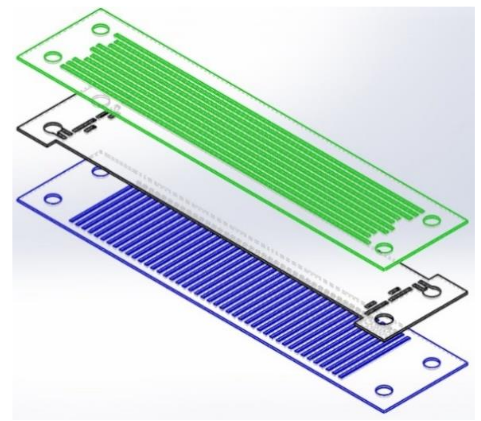
2.2. Bipolar Plate and Reactants Flow Field Design
A double serpentine flow field design was selected for the anode side, and straight channels for the cathode side. EG sheets were used to prepare the bipolar plates. The idea is to cut the anode and cathode channels on separate sheets and then join them together with a third sheet in the middle to isolate the gasses. An exploded-view schematic of the three-layer bipolar plate is depicted in
Figure 1.
2.3. Design of Cutting Molds
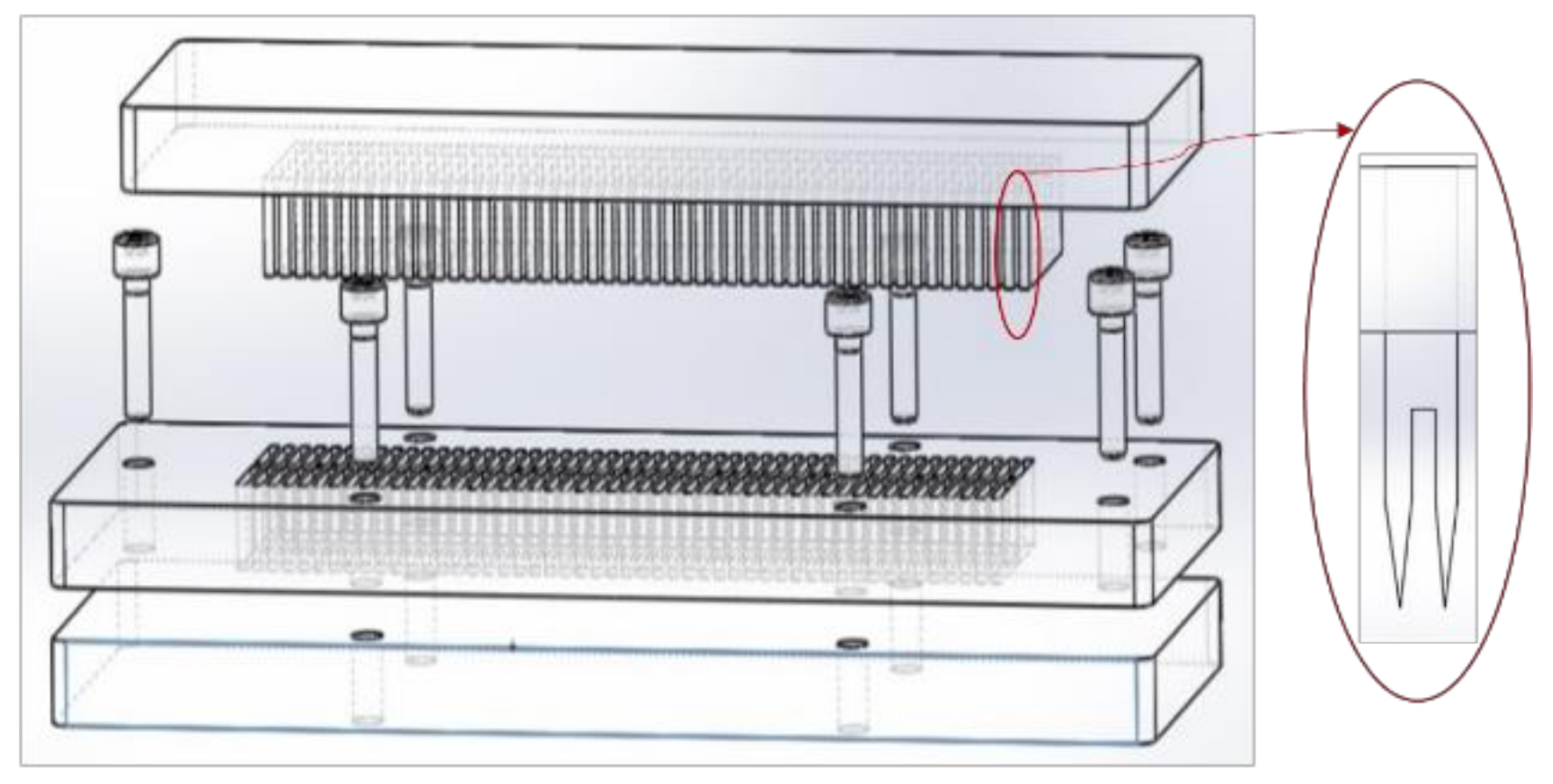
Three different cutting molds were designed for cutting flow field channels on the anode, cathode, and middle plate sides, respectively. Each of the molds consisted of three parts:
1. Male part having sharp cutting blades of the desired channels dimensions;
2. Female part having grooves of the desired channel dimensions;
3. A stopper polytetrafluoroethylene (PTFE) plate for supporting the female part and preventing the blades from further movement.
The idea was to hold the thin EG sheet between the female and the stopper plates and to cut the channels by the male part using a hydraulic press. The blades of the male piece were arranged as double blades to avoid the bending of the sheet to the channel. The grooves on the female part guided the blades to cut the channels with desired dimension, whereas the bump region supported the EG sheet edges during the process of cutting. The stopper plate was a hard PTFE material which can withstand the pressure from the hydraulic press without damaging the cutting blades. The blades on the male part were placed apart according to the desired dimensions. The schematic architecture of the mold system (for the cathode side) is shown in
Figure 2.
2.4. Preparation of Bipolar Plates
Three-piece cutting molds were used to cut the fuel flow channels for the anode, cathode, and middle plates. The molds cut the sheets into size and create gas flow channels in a single press punch. The whole process consisted of the following steps:
1. EG sheet was clamped in molds and cut into size, creating fuel flow channels.
2. Electrically conductive adhesive was applied on the anode and cathode pieces using a semi-automatic screen printer (ATMA AT-45PA) to get a uniform layer.
3. The three pieces were gently pressed together for proper adhesion.
4. The assembly was cured at 100 °C for 15 min using a BINDER FD 53 forced convection oven.
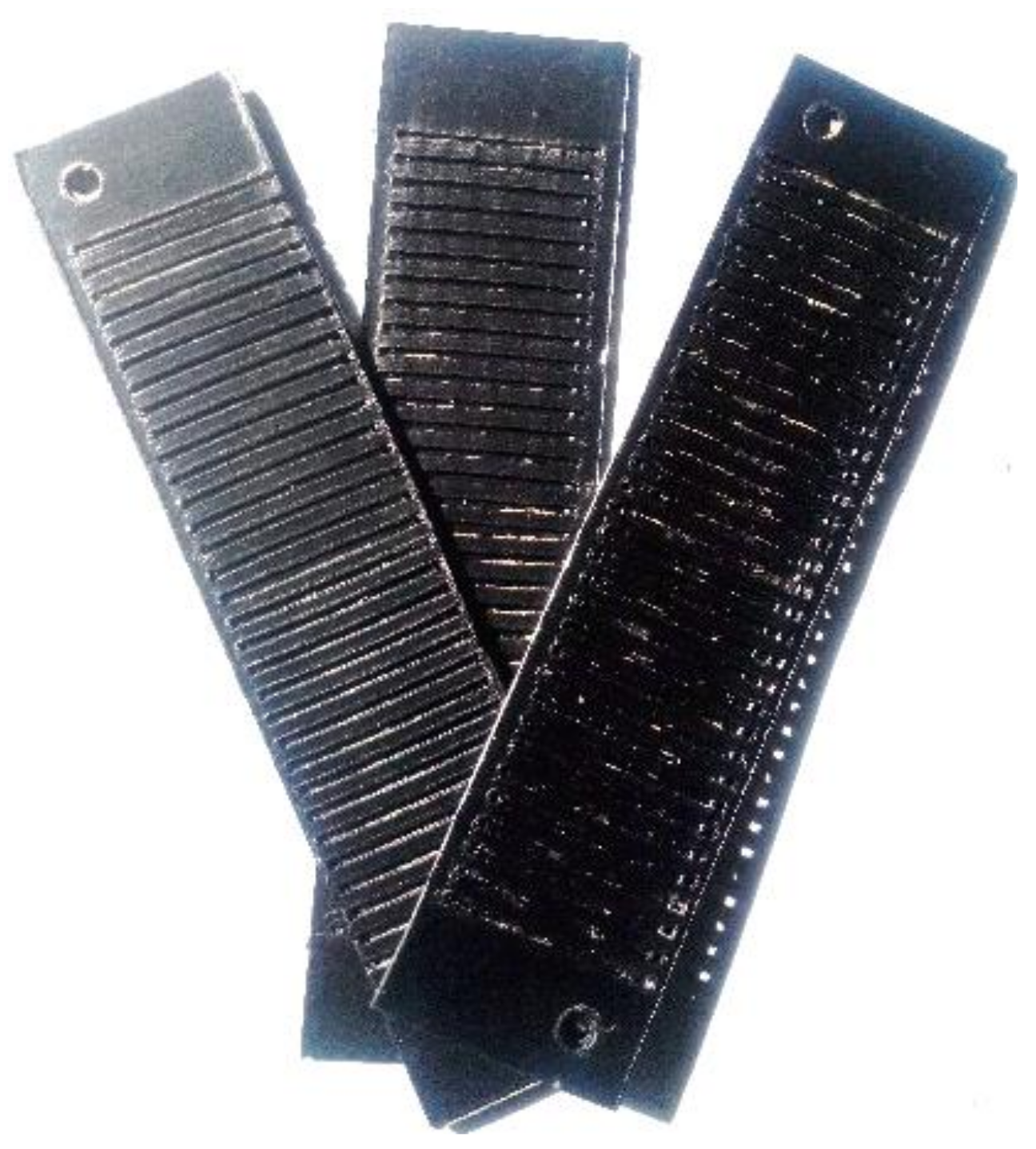
5. Finally, the finished parts were cleaned before being placed into the fuel cell assembly.
A photograph of the three-layer developed bipolar plate (cathode side) is shown in
Figure 3.
2.5. Membrane Electrode Assembly Preparation
A commercially available membrane and catalyst were used to prepare the standard MEAs that were used to test custom-made bipolar plates. The catalyst slurry was prepared from the commercial catalyst both for the anode and cathode layers with different loadings. The decal transfer method was used to prepare the MEAs. The catalyst slurry was first coated on Teflon sheets and then transferred to commercially available Nafion XL with a hot press. Custom-made MEAs were prepared with Platinum (Pt) loadings of 0.45 mg.cm−2 both for anode as well as cathode.
2.6. Fabrication of Fuel Cell
After the fabrication of all the components, a single-cell assembly was prepared. Eight bolts were used to fasten the cell assembly, and the appropriate torque was applied. Gas inlet and outlet valves were installed on the end plate. Since the fuel cell stacks were designed as an air-breathing system, a small fan was installed in order to provide a sufficient oxidant to the cathode and to cool the cell by forced convection.
2.7. Characterization of the Bipolar Plate
Three-layer composite bipolar plates were characterized in terms of mechanical (flexural) strength, electrical conductivity, and contact resistance, and compared with target values. Experiments were repeated with several specimens to ensure repeatability. Standard procedures were followed for the characterization of bipolar plates in accordance with the methods available in the literature [
20]. The goal was to achieve the bipolar plate targets set by the Department of Energy (DOE), as shown in
Table 1 [
21].
2.8. Mechanical Strength Measurements
Several tests and techniques are used by researchers worldwide for determination of the mechanical strength of bipolar plates. These include the tensile strength test method, the compression test method, and the three-point bending method. The three-point bending method was selected for our measurements since this method represents the tensile and compression stresses occurring simultaneously on bipolar plates during the assembly or compression of PEM fuel cell stacks [
22].
The three-point flexural strengths of the custom-made bipolar plates were evaluated using the Instron model 5569 universal testing machine. The mechanical strength measurements were recorded according to ASTM D790 standard (Standard Test Methods for Flexural Properties of Unreinforced and Reinforced Plastics and Electrical Insulating Materials). Specimens with dimensions 16 × 60 mm2 were prepared for mechanical strength measurements. The supporting span distance was set as 40 mm wide, moving at a constant cross-head speed of 1 mm/s.
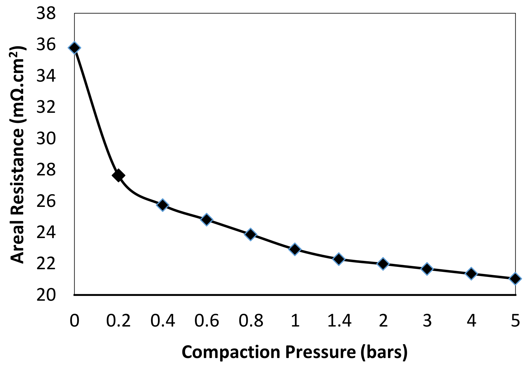
2.9. Contact Resistance
The contact resistance between layers of the PEM fuel cell showed a stronger effect on cell performance than the bulk resistance of those layers. The three-layered EG sheet with a thickness of 1.8 mm was placed between two carbon papers, each of which was in contact with a gold-coated metal plate on the opposite side. While a constant current was passed through the two gold coated plates, the potential difference between these plates was measured. The measurements were repeated at various compression pressures applied through the apparatus in order to examine the effects of compression pressure on the contact resistance. The contact resistance was calculated based on Ohm’s law.
2.10. Electrical Conductivity Measurements
The in-plane electrical conductivity values of the specimens were measured using a Jandel RM3-AR (Jandel Engineering Ltd. Linslade Beds, UK) four-point probe electrical conductivity measurement tool. Through-plane electrical conductivity values of the samples were measured using the custom-designed plates, each including four gold-plated copper probes. An adjustable hydrostatic press was used in parallel with a Keithley Model 2000, 6½ digit digital multimeter (Tektronix, Inc. Beaverton, OR, USA). The conductivity measurements were recorded under 140 N.cm
−2 pressure, and all four probes were recorded for all specimens [
23].
2.11. Weight Measurements
The weight of the finished bipolar plates was recorded using a precise (five-digit) weighing balance TB-215D (Denver Instrument Bohemia, NY, USA). The weight density and weight per kW calculations were made to test that DOE targets were met and to make comparisons with previous studies.
2.12. Fuel Cell Tests
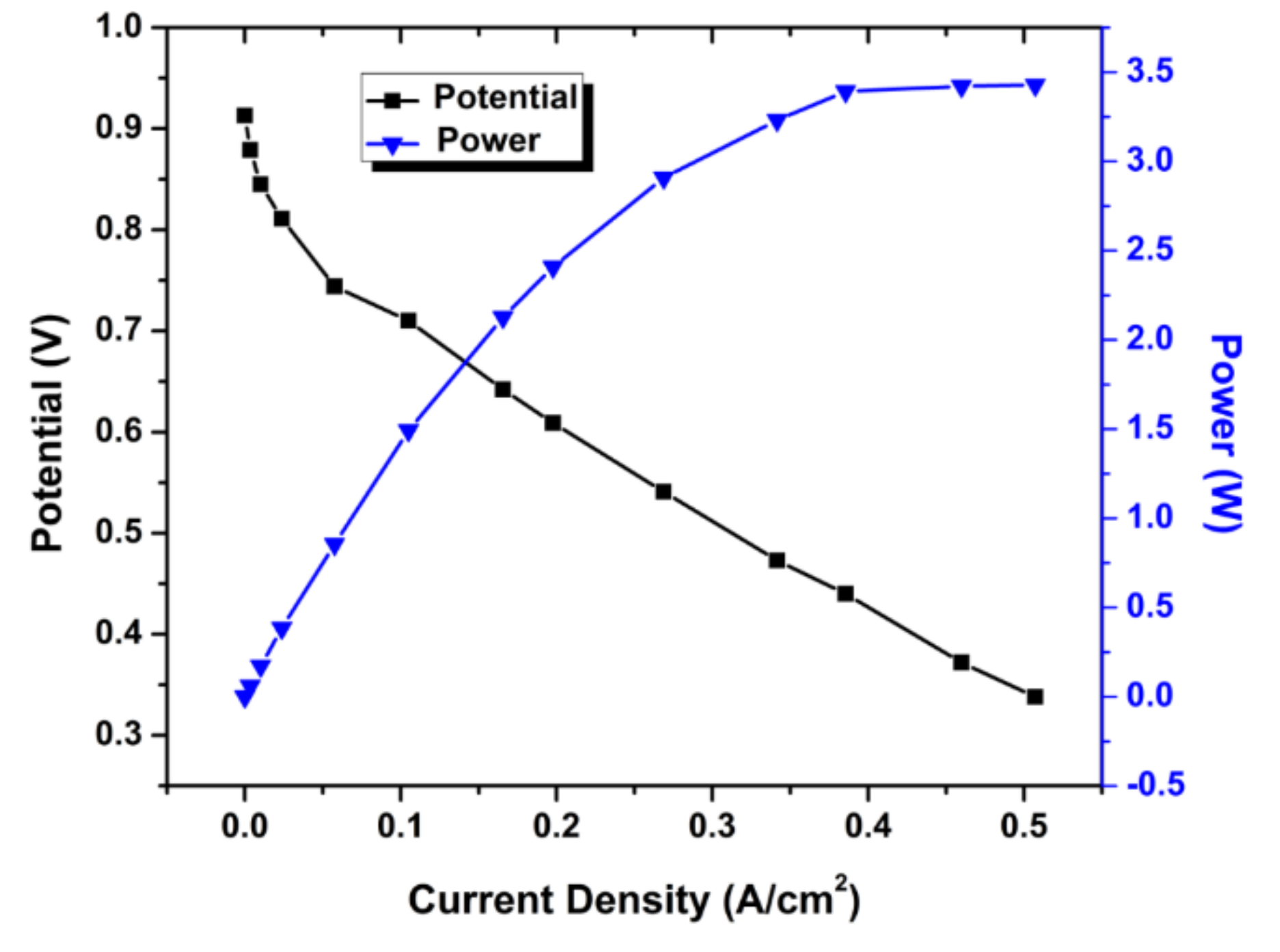
Finally, the single-cell assembly was tested for actual performance. The custom-built fuel cell test station at our lab was used for performance testing. The fuel cell performance experiments were performed at 60 °C, while hydrogen and oxygen were purged and fully humidified at 50 °C. The gas flow rates were kept constant for both anode and cathode, and were equal to 0.2 L.min−1 and 0.4 L.min−1, respectively. The MEAs were conditioned (humidified and activated) before recording the test results. The polarization curves were obtained while decreasing the potential slowly by withdrawing the current. Polarization data were recorded after six continuous cycles.
4. Conclusions
The main focus in this study was to prepare light-weight and low-cost bipolar plates using a novel design and fabrication method. The purpose was to float an idea about this cost-effective and easy-to-manufacture technique for fuel cell bipolar plate production at a lab scale. Efforts were put together to prepare three-layer expanded graphite–polymer composite bipolar plates using a conductive epoxy adhesive. Low-cost cutting molds were designed and fabricated for the creation of reactant gas flow fields. Alternately, wire-cut molds could also have been used for same purpose. The final product was evaluated in terms of its weight, cost, and performance for the PEM fuel cell. This technique enabled us to achieve the desired bipolar characteristic parameters. Since commercially available material (EG) was used for the fabrication of the bipolar plates, it was assumed that it would exhibit the same electrical and chemical properties mentioned in the data sheet. The authors focused only on the mechanical design and fabrication process here. Therefore, the chemical stability, resistance to corrosion, impermeability to gases, etc. are not included in this characterization. The results are very encouraging for the production of PEM fuel cell bipolar plates using this design and manufacturing technique. Although the cost and weight did not meet the DOE targets, they can be drastically reduced by getting large-scale production prices on the materials used, reducing the production cycle time by using process automation, getting higher current and power densities using efficient MEAs, and optimizing the operating parameters. It is expected that this work will help the industry to realize light-weight, low-cost, and high-performance PEM fuel cells to meet future needs.


