1. Introduction
The definition of design methods varies across industries, from the design of ideas and concepts to detailed technical and manufacturing drawings [
1,
2]. Mechanical design of parts and assemblies have significantly progressed over the last 30 years from manual drawings to parametric computer-aided design suites (CAD) that enable enhanced design functions [
3,
4]. Over the last decade, engineering design has further evolved from a feature-based to a function-based mentality; parts are now morphed based on their functional requirements and loading state [
5]. With the conventional parametric design, the design engineer decides upon the most important features, generating the initial shape of the design, and then further determines the exact dimensions for the part to perform the required specifications [
6,
7,
8]. With the algorithmic methods, the designer decides upon the morphing equation, its parameters, and the specific space inside the build volume that the algorithm fills with structures of material [
9,
10]. The existing design schools for designing a mechanically functional or non-functional component are categorized in
Table 1.
The algorithmic methods branch in two main and dissimilar subcategories, namely: topology optimization and generative design. Both approaches start from the build volume and add or subtract geometrical entities to morph the part, and both need the design engineer’s input at the end of the design stage to determine which features and which design variant is to be manufactured. Therefore, additional additive manufacturing (AM) buildability knowledge is required to choose the optimum part variant at the end of the design process [
3,
20]. This feature and part variant selection is the first point of the design process where manufacturability concerns begin to appear (see
Table 2 Definition of terms), as certain geometries and features can make the product’s manufacturing unviable with AM.
The very specific goals of the current design optimization methods generate complex parts, making it impossible to be realized with conventional manufacturing. The resulting parts are appealing for additive manufacturing yet display low AM manufacturability. Modifications are then required on a second design stage to address problematic aspects of the design and increase the part’s manufacturability [
27,
28]. This additional design modification stage highlights the need for a design method, where manufacturing specifications and the component’s functionality simultaneously act to shape the design and optimize the AM process to make it economically viable [
6,
29]. Among the different causes that can lead to a part’s manufacture failure or bottleneck the AM production line, the part design is a crucial factor (see
Figure 1). The motivation of this work originates from the part’s design importance for the AM uptake [
30].
To meet the challenges associated with design optimization for additive manufacturability, the authors propose a novel optimization method that simultaneously takes into account the structural stress as well as additive manufacturability to form the part geometry. The resulting part is designed from scratch based on its loading scenario. Therefore, predetermined part designs and geometries with multiple fixed features and surfaces are not the focus of the proposed method.
2. Materials and Methods
2.1. Manufacturability for Additive Manufacturing
The initial step of developing an algorithm that optimally distributes material and abides by the AM rules is to properly define the term manufacturability for the AM technologies to fully utilize their advantageous freeform nature.
Manufacturability of an AM part is not a duality of can-or-cannot be manufactured. The design aspects and features, that are manufacturable, vary across different AM technologies [
21], due to their different build mechanisms, yet the same objectives of reducing manufacturing costs and optimizing the overall process remain. That is, the design efforts of alternations and adaptations for the specific manufacturing technology can be screened from the AM manufacturability indicator (
Figure 2).
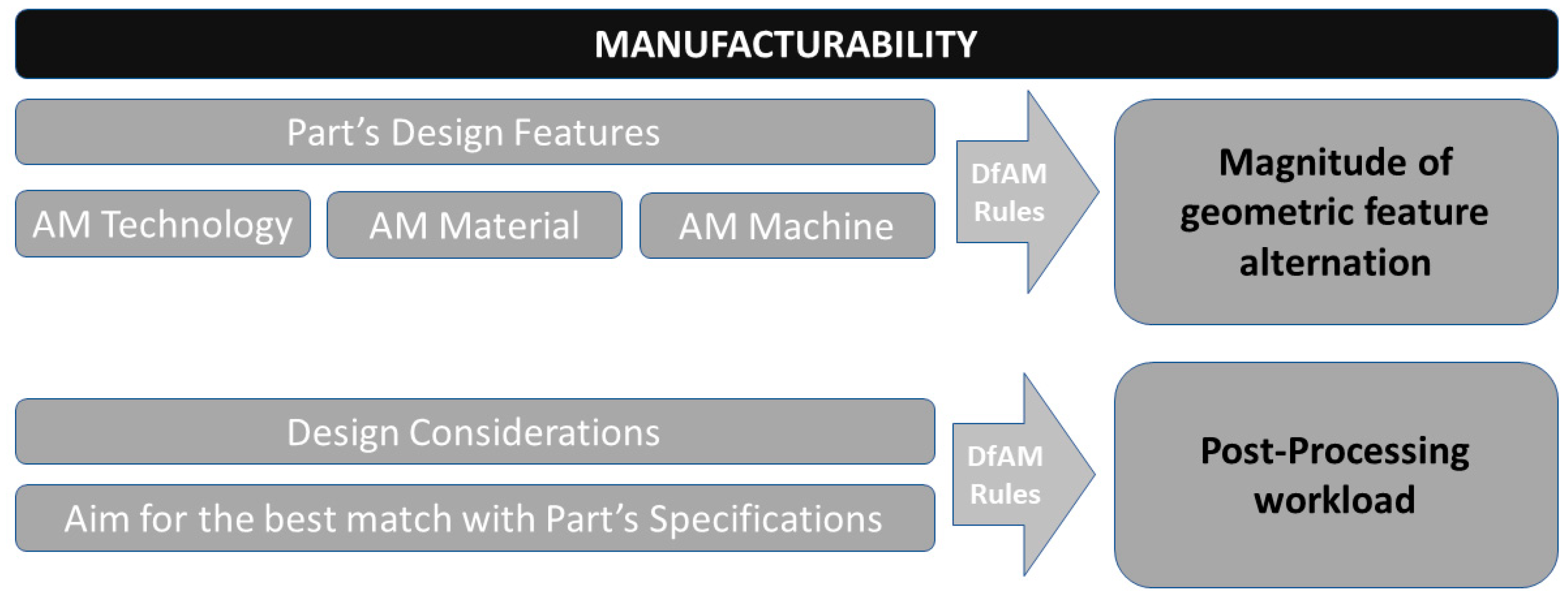
The determination of the AM manufacturability at the part design level starts from the identification of the part’s design aspects and their comparison with the AM technology’s capabilities [
21,
22]. This cross-check results in several features that are by definition non-feasible for manufacturing or require support structures (e.g., out-of-limit overhanging geometries). The magnitude of the design modifications required to correct the non-feasible to manufacturable features is the first leg of the part’s AM manufacturability. This subset also includes the extent of the required support structures to secure the build while being manufactured.
The second leg refers to the post-processing load the part must go through to reach the desired state and meet the user’s requirements. The post-processing workload can be reduced with properly manufacturable designed features (e.g., overhanging geometries orientated within limits).
The framework to determine a part’s additive manufacturability is shown in
Table 3.
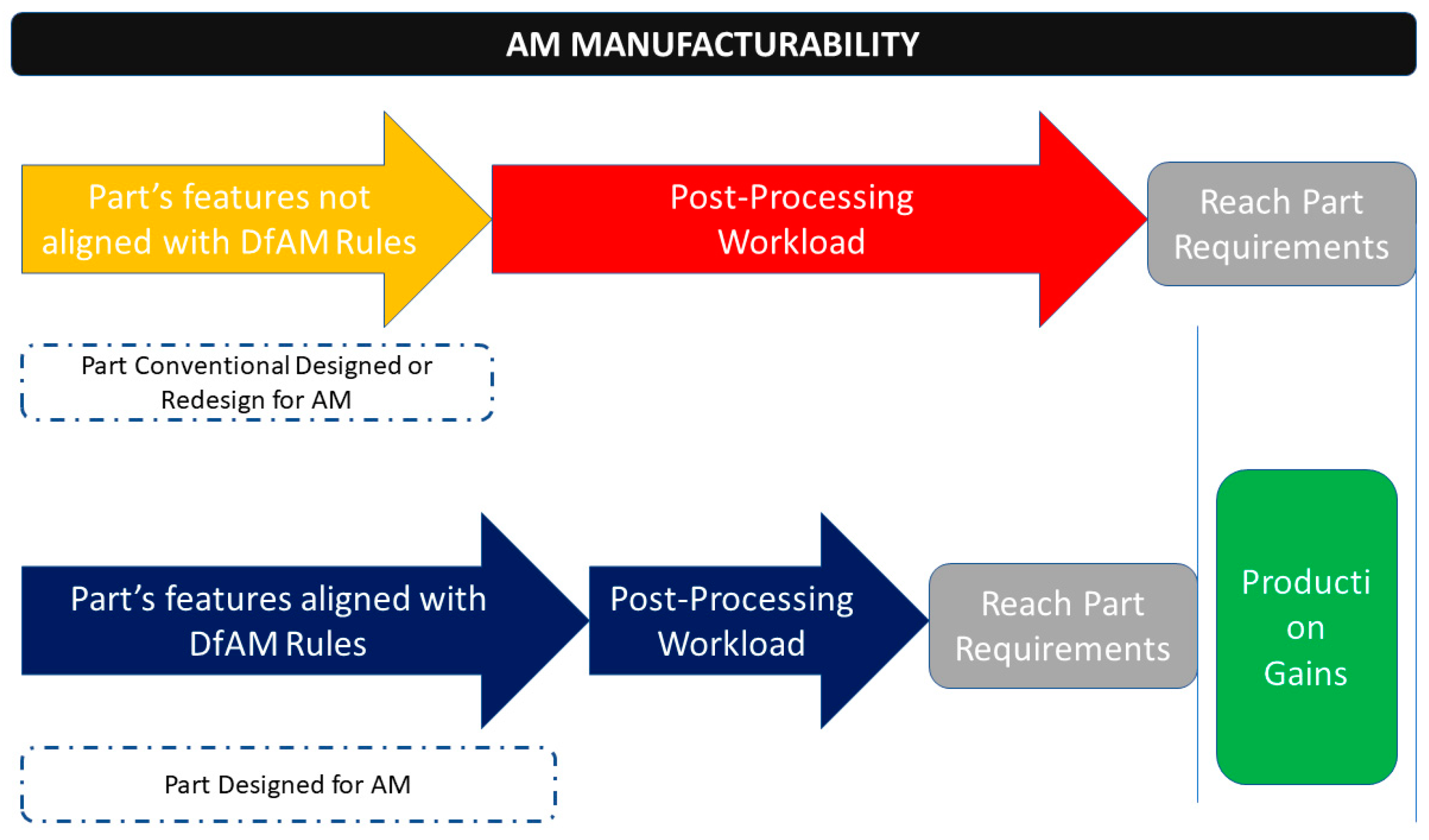
The overall AM manufacturability indicator is not one-dimensional as it describes the easiness of the design to be additively manufactured without alternations, the addition of support structures, and the extent of the post-processing load that the part requires to meet its final requirements. This affects the production performance and can be resolved with the implementation of direct energy deposition (DED) Design for Additive Manufacturing (DfAM) rules to the part’s design (
Figure 3).
2.2. Shape Optimization Method for the DED AM Process
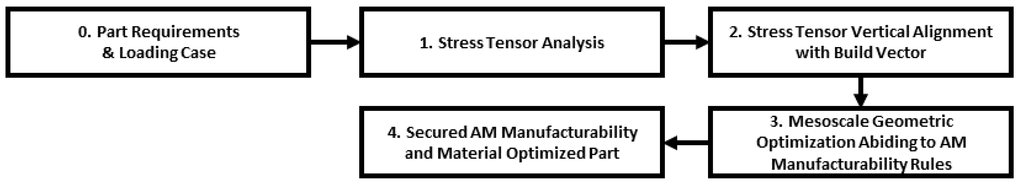
This novel morphing method proposes a specific subtraction of finite design voxels to ensure optimal AM manufacturability. A morphing method is proposed to achieve shape optimization and AM manufacturability is checked by reducing the complexity of the additively manufactured part (
Figure 4).
2.2.1. Stress Analysis of the Build Envelope
The first step of the shape optimization method is to determine the stress that is developed within the part’s material. The loading scenario and boundary conditions are initially applied, and stress is calculated for the entire build envelope. The computation of the internal stress is of dual purpose: First, the magnitude of the stress tensors determines which elements are candidates for subtraction. Second, the direction of the stress tensors will be used to decide the part’s build orientation. As the part is morphed, the new resulting domain is further analyzed.
2.2.2. Build Orientation
The next step in the proposed method is to orient the part inside the build chamber. A multi-criterion build orientation tool to weigh all the part’s design considerations [
21] is something that has been researched and attempted, yet with no converging solution [
34]. The design consideration accounted for in this step is to optimize the structural performance. The metal direct energy deposition AM technologies manufacture components that have different mechanical properties along different axes within the part’s material. These deviations originate from the metallurgical material forming process (e.g., fusion, sintering, melting) and the fundamental layering nature of AM. Up to 300% difference between vertical and horizontal orientations have been reported for mechanical properties of tensile strength and strength to fatigue due to the AM material anisotropy [
35,
36,
37]. Although numerous compensatory post treatment techniques exist that resolve anisotropy and microscopic defects, such as polishing or hot isostatic pressing of the Ti-6Al-4V parts [
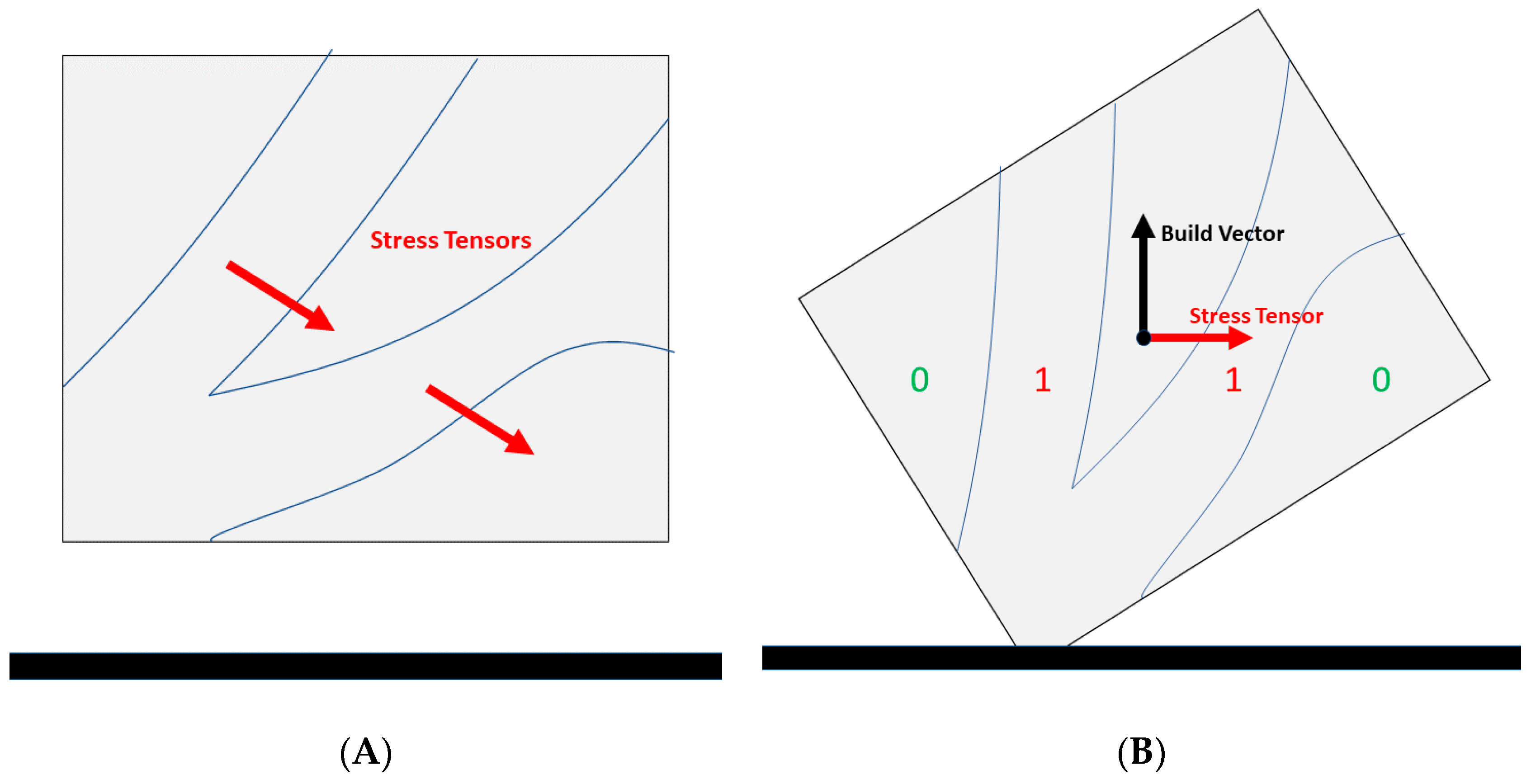
38], the industry’s direction towards medium to large, as-manufactured metal components, calls for this anticipation of material anisotropy. The material anisotropy is managed by vertically aligning the stress tensors—developed from the external loads applied on the building envelope—with the additive manufacturing building vector (perpendicular to the building layer). Manufacturing with this orientation secures that the maximum stresses are received by the AM material’s best directional strength. The internal material’s anisotropic strength comes from the fundamental build nature of the AM technologies and the micro and mesoscale imperfections imposed to the final part [
29,
39] (
Figure 5).
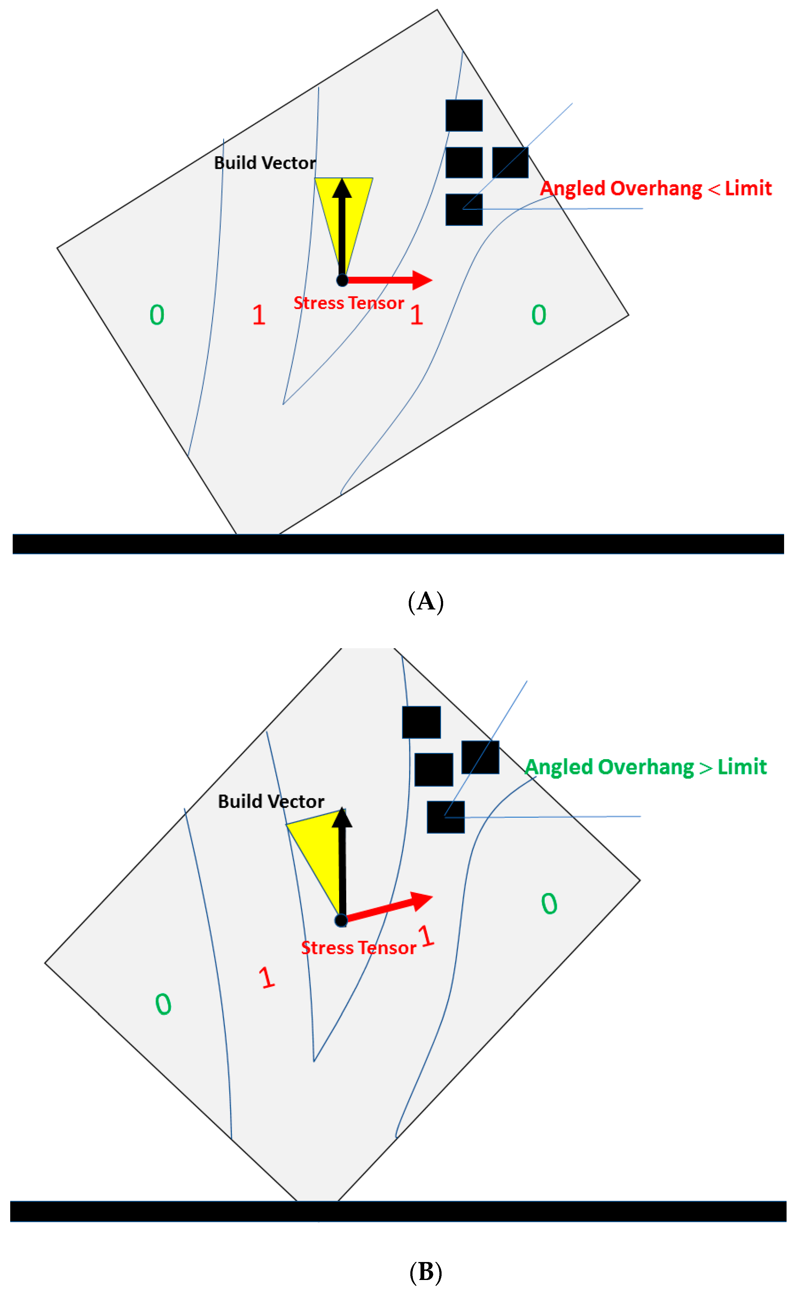
The second leg of this step is to grant some flexibility to the algorithm when geometric features come as a pre-fixed specification of the part. It is an allowed orientation rotation margin and it aims to avoid excessive generation of support structures. The allowance margin refers to the limit of degrees the optimum build orientation can deviate from, so that an overhanging surface can be manufactured without supports.
Figure 6A shows an overhanging feature, where the slope of its surface makes it un-manufacturable given the orientation and the objective to manufacture without support structures. That is, the part can be rotated within the allowed orientation margin in order to orient this feature, relevant to the AM build vector, to make it manufacturable, as shown in
Figure 6B. The extent of the orientation rotation margin is determined each time by the objectives of the design engineer and the production’s needs [
40]. This is to anticipate the scenarios where the balance between structural performance and the addition of supports shifts.
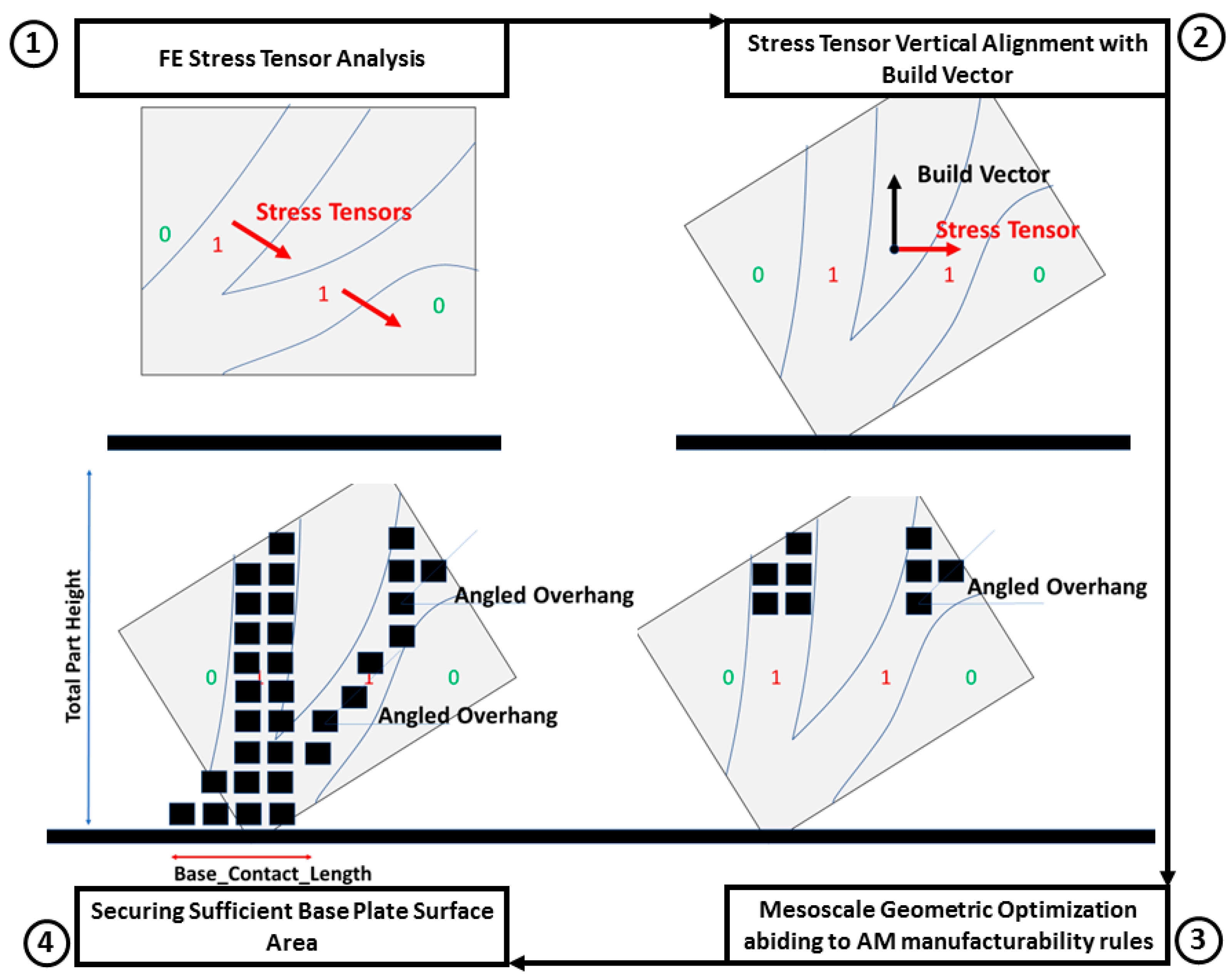
2.2.3. Top-Down Mesoscale Geometric Optimization Abiding to AM Manufacturability Rules
Following the definition of the build orientation comes the material removal based on the loading state. A top-down layer scanning direction is followed. A voxel is removed from the matrix when both cases are valid:
- (i)
The load is below the stress threshold;
- (ii)
The resulting geometry abides by the DfAM rules.
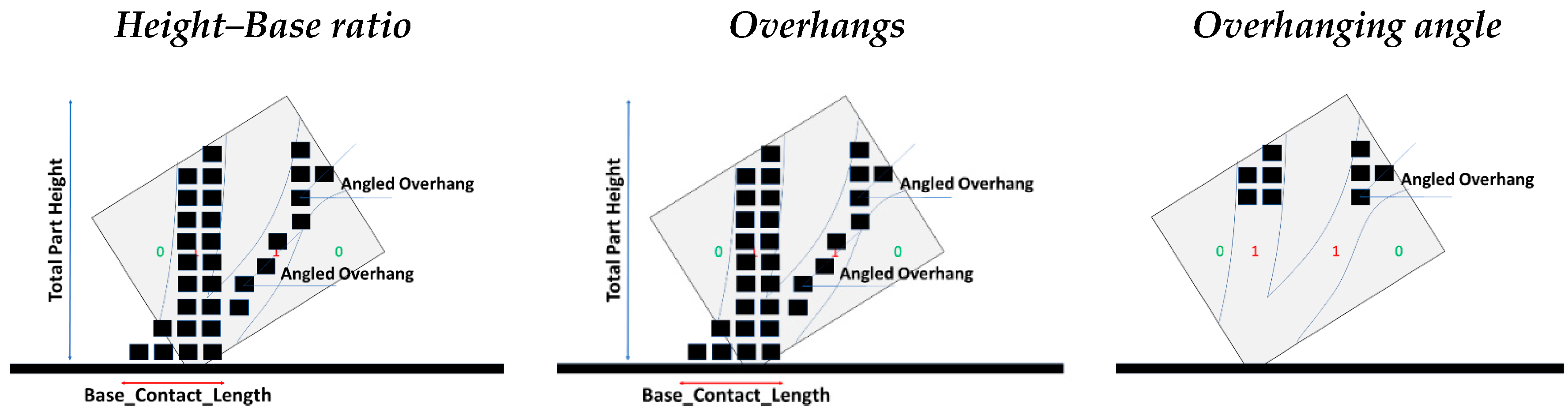
For demonstration purposes, three major DfAM rules were chosen based on the freeform fabrication mentality of the metal direct energy deposition (DED) technology [
34] (
Figure 7). Depending on the specific AM technique, the equivalent buildability restrictions are to be considered.
The first DfAM rule is highly targeted to increase the part’s AM manufacturability. The contact length of the base layer performs crucial functions for the entire DED build as thermal and mechanical stresses can be concentrated or diffused if chosen properly. The part’s height to contact length ratio is introduced to monitor and define the above need through a geometric feature. This ratio is defined in Equation (1) and illustrated in
Figure 8.
The nature of the function between the contact length of the current layer being built and the previous one dictates the required height–base (HB) ratio for the optimum part’s manufacturing. This is due to the structural and thermal phenomena that are being developed [
41]. Oblong geometries (high HB ratio) tend to increase the difficulty of controlling the part’s manufacturing as they have low heat convection and are prone to cracking and detachment from the build bed. The target HB ratio and its margin are further quantified with more thermodynamic insight into the status of the AM process’s nature and the part to be realized [
42,
43].
Following with the overhanging DfAM rules, the shape optimization algorithm scans the building envelope with the top-down direction, deriving the elements’ load status from the stress analysis and determining the candidate for extraction elements. Next, the algorithm also checks if the remaining geometry creates features that abide by the aforementioned DfAM rules. If the candidate for extraction element does not contradict any rule, its material is removed from the geometry, and the morphing continues. The elements’ possible status is presented in
Table 4.
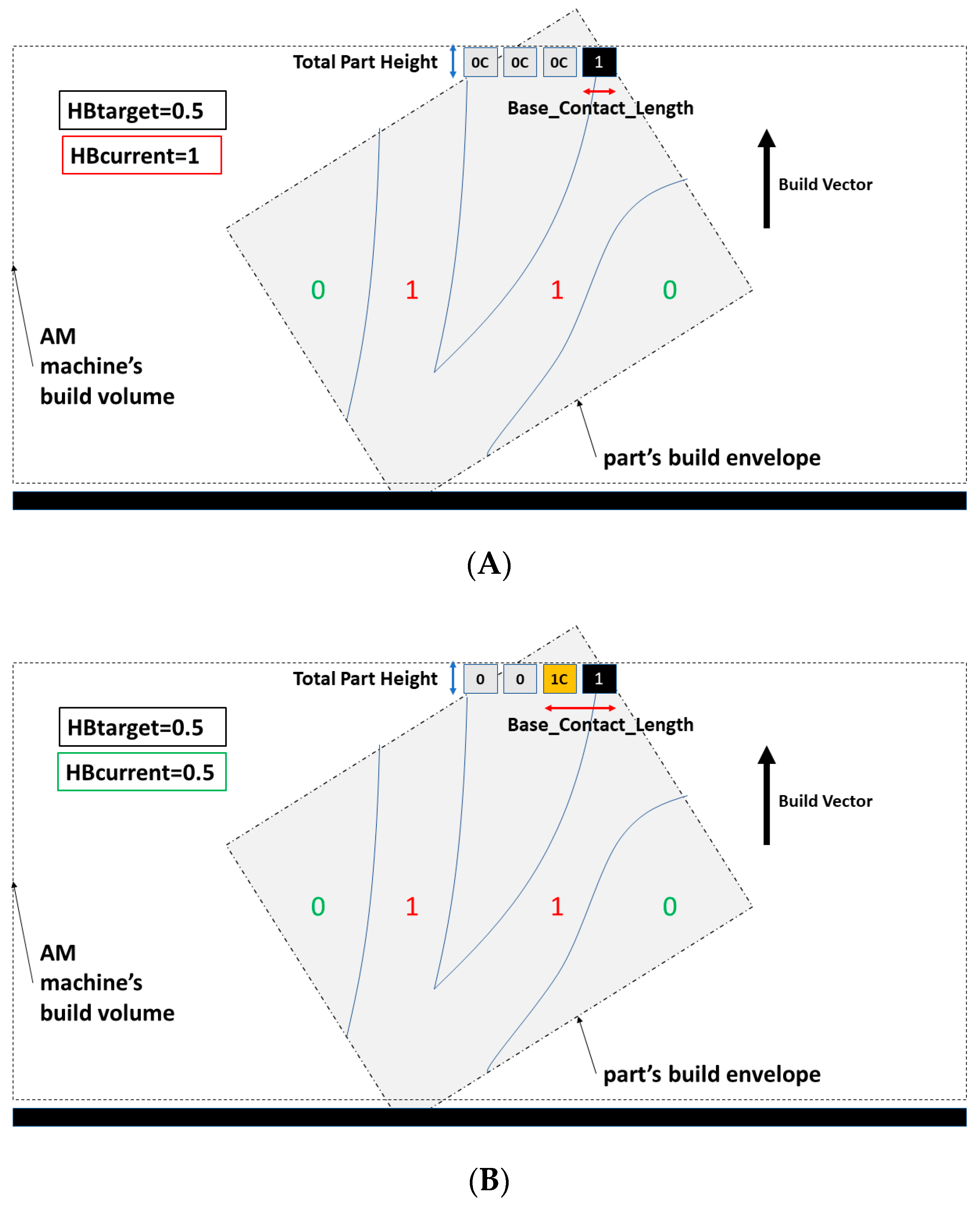
The first iteration of the shape optimizer starts from the last (Nth) layer of the previously oriented build envelope. At this point, the only factors morphing the part are the targeted HB ratio and the elements that are loaded (
Figure 9). The elements that will remain from the first iteration should provide sufficient contact length. The loaded element gets a value of 1 and the rest of the elements in the same layer the value of 0C. The DfAM rules are checked and the candidate elements that are needed to secure the AM manufacturability change their status from 0C to 1C to provide sufficient contact length and not over the limit overhangs.
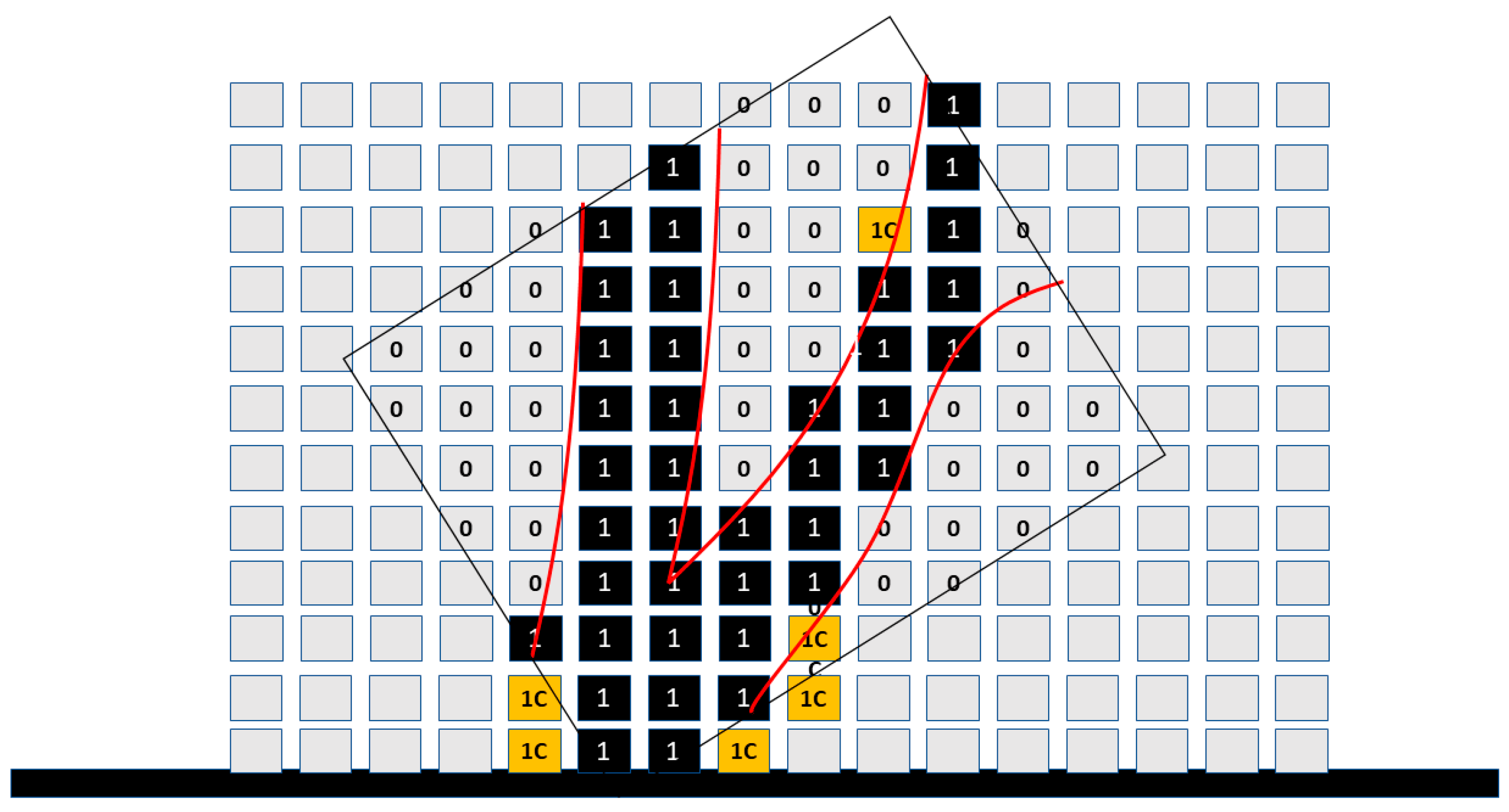
The current domain consists of elements with values of 0, 0C (material is subtracted), and 1, 1C (material remains). The algorithm runs again for the next layers and shapes the design domain resulting in the part shown in
Figure 10.
When all the layers and their elements have been calculated, the morphed shape contains elements of 0 and 1, 1C; where 0 is elements empty of material and 1, 1C elements with material. The 1C elements do not represent the optimal material distribution; however, they increase the AM manufacturability of the part. In contrast to conventional topology optimization, the final part’s geometry contains low stressed elements so that the resulting shape has optimized AM manufacturability. This is at the expense of minimized weight. To create a clear picture of the elements that serve topology optimization and the ones that serve AM manufacturability the following indicator is introduced:
The summarized method’s flowchart is presented in
Figure 11.
3. Results
Case Study
To validate the proposed method, a case study was implemented. A simplified two-dimensional (2D) cross-section of a part under load is morphed. The part dimensions and the load scenario were derived from a similar formula student component [
3]. Simplifications were required to adapt the component for the needs of this work. The resulted part from the proposed AM shape method, to be produced with an LMD-w technology, is significantly different from the original FS part that was produced with conventional machining. A two-dimensional domain of 20 × 30 elements with a load case of Fx = 10 N and Fy = −7.5 N was used. The cross-section dimensions are 100 × 150 mm. The point load is applied at the bottom left of the rectangular domain and remains at these geometrical coordinates as the part’s shape starts to morph (
Figure 12). The meshing of the domain was chosen to be quadrilateral and rough for better visualization and short computational iterations.
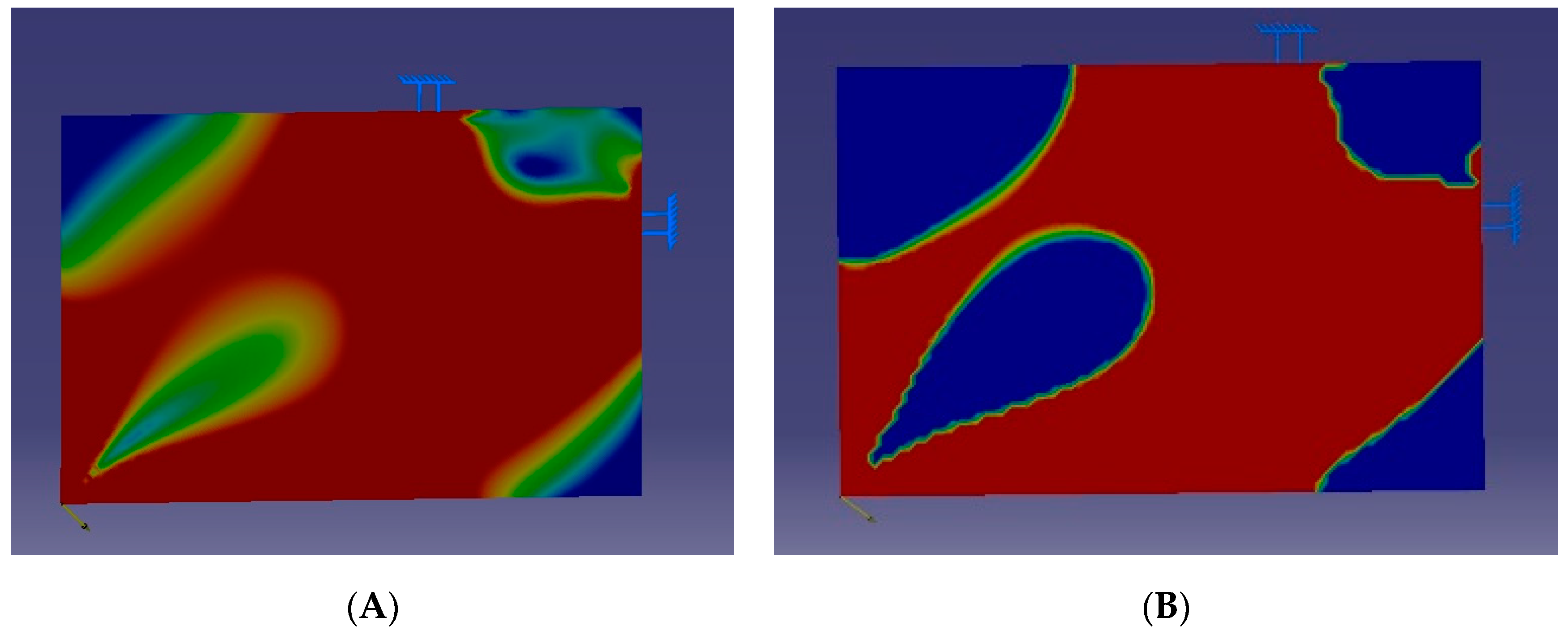
The first step is the computation of the internal stresses for the entire build envelope. The stress distribution in the building envelope shows high- and low-stress areas on its elements (
Figure 13A). Setting a threshold and filtering the stressed voxels, the design domain takes the dual 0 or 1 shape form, as seen in
Figure 13B.
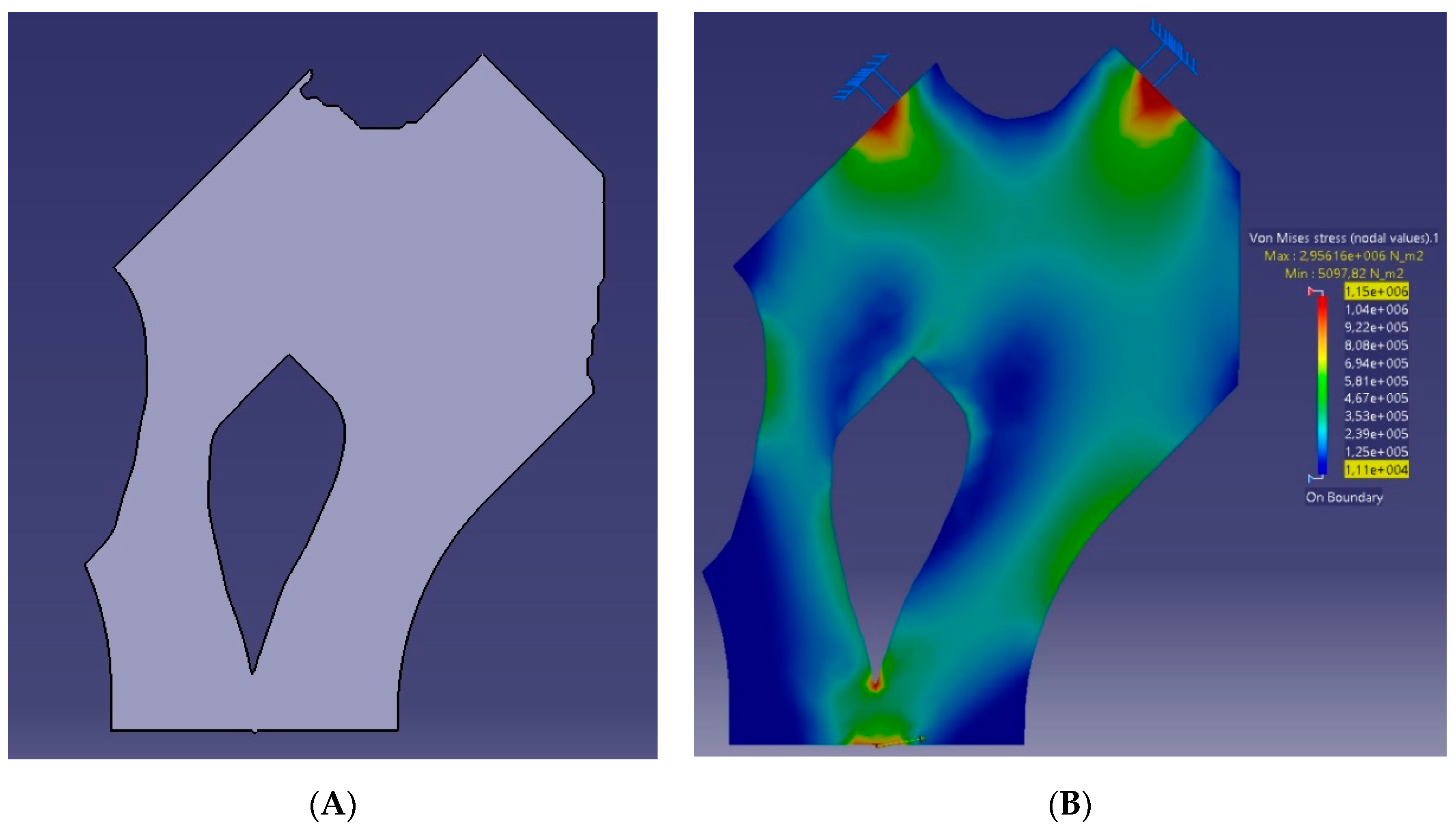
The next step is orient the stress and build vectors. The element characterization and extraction followed the above mentality of the DfAM rules from the DED buildability restrictions. The material of a voxel is removed if it is below the stress threshold and the resulted geometry abides by the buildability restrictions of the DED AM technology. The HB ratio was set to 2.5 in order to provide sufficient clamping area for the base plate of the machine. The resulting part shape is shown in
Figure 14.
To screen the status of the voxels that serve topology and the ones that serve AM manufacturability the topology optimization and AM manufacturability indicator (TMI) was calculated. The surface areas were used as input in Equation (1). The part has a Value_1_area of 10,285.2 mm
2 and a Value_1C_area of 1523.4 mm
2. This result of the TMI was 0.871 or 87.1%. This value shows the material sacrifice for AM manufacturability against topology. In this particular case, it can be seen that the added material serving the AM manufacturability is far less than the material used for the part to receive the developed stresses. The differentiating areas in the parts cross-section morphing can be seen in
Figure 15. The geometric features that were created differently from the AM shape optimization algorithm were the overhangs in the lower left and upper right corners.
Following a topology optimization (TO) method such as SIMP, these two areas would result in overhanging features with an overall decreased AM manufacturability for the part. Instead, the 0C design voxels in these areas changed their status to 1C, and the overhanging features resulted in design features that are within the manufacturing abilities of the DED technology.
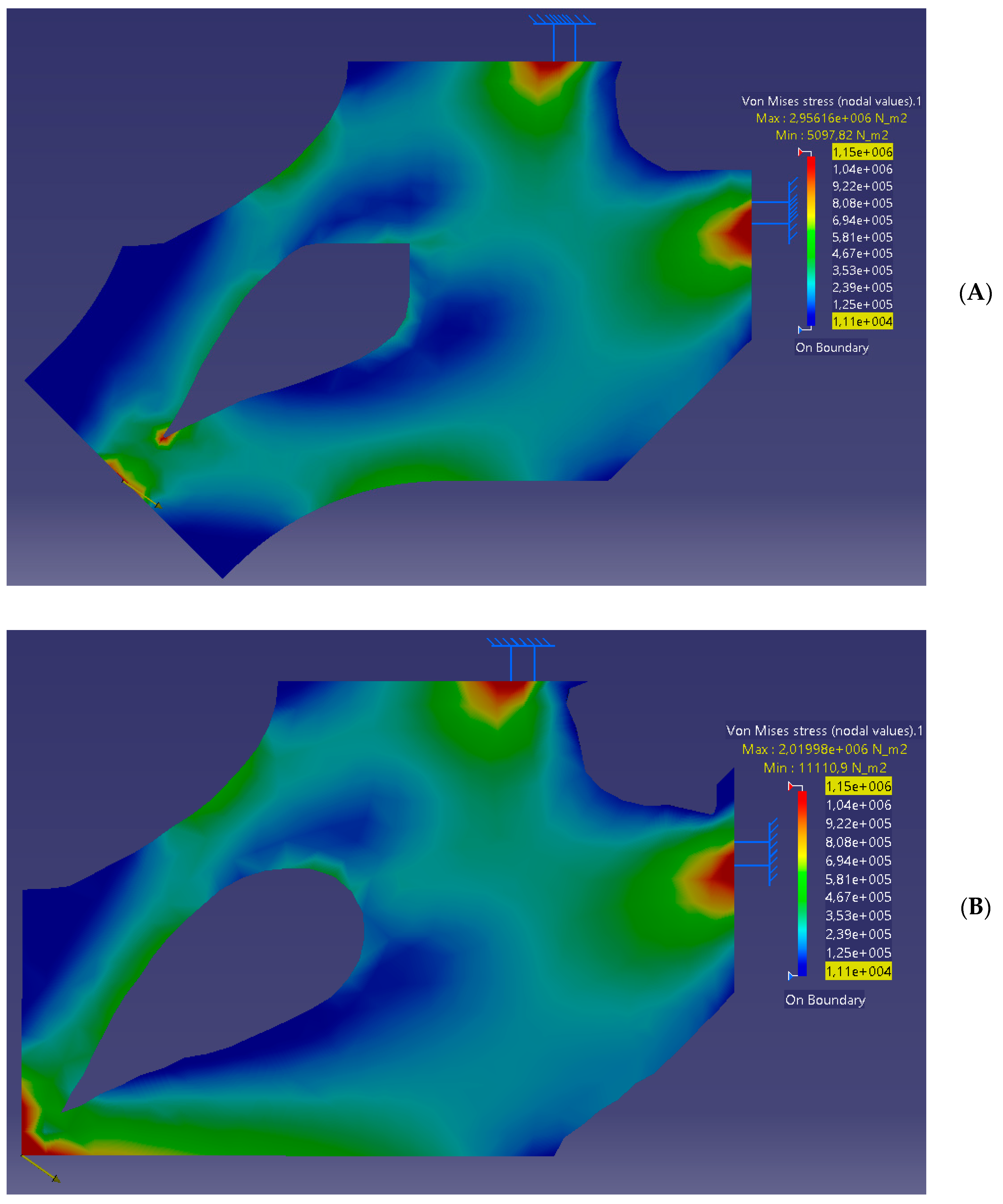
To investigate the effect in the stress magnitude and distribution, a second analysis was performed between the AM part and a part that was morphed only from TO using SIMP parameters. The finite element analysis of these two parts can be seen in
Figure 16.
The maximum developed stress in the AM shaped part was 2.11 MPa and at the TO part was 2.02 MPa. The 4% difference of the maximum developed stress of the AM part compared to the TO part was located in the voxels of the edge where the load is applied. The added material in the AM part caused a different stress distribution and thus stress magnitude within the design domain.
4. Discussion
The proposed AM design method is a morphing algorithm that at the early design stages compensates for both optimal material distribution and best manufacturability for the AM parts.
The resulting part geometry shares commonalities with the SIMP method, which offers optimum material distribution. This AM shape optimization method, however, addresses the AM manufacturability simultaneously with the early part shaping instead of addressing it at a post-design stage that follows the topology optimization [
43,
44].
The extent of which the part design sacrifices material distribution for the AM manufacturability is a design parameter, and subject to the method’s margin limits (
Section 2.2.2. Build Orientation) and the selected DfAM rules. It is case dependent and varies according to the input of the design engineer and the needs of the part production. There are cases where material distribution outweighs the post-processing workload of the support removal procedures thus providing higher design freedom against the AM buildability considerations. The proposed performance indicator (TMI) screens this material sacrifice between topology optimization and AM manufacturability.
The differentiating aspects of this method, compared to the previously proposed ones, can be seen in the second and third steps of its summary:
The design domain’s stresses are determined;
The voxels are characterized layer by layer with a top-down scan of the domain;
Material is subtracted until a topology is optimized and AM manufacturable part is generated.
The resulting geometry, from the case study, has an additional 12.9% of overall material to secure best AM manufacturability and a 4% difference in the stress development. The small differences originate from the fact that the general shape of the part is imposed by the topology mentality and goals, but the geometric features and their details are imposed from the DfAM rules.
5. Conclusions
It was found that the proposed AM shape optimization method carries similarities with existing topology optimization methods. The distinguishing difference of this work is that the shape morphing of the part initiates and progresses with the AM buildability constraints addressed in parallel with the material optimization.
As for future work, the proposed shape method is to be expanded in the third dimension and the iterative steps and the characterization of the design elements are to be integrated into an automated design tool. Some of the design steps of this method will transition from the 2D domain to the 3D equivalent property; for instance, the HB ratio will have the base surface as input instead of the base length. Other steps were proven to be more complex to their three-dimensional implementation such as the overhang feature recognition, where a rotating scan around the build vector is required in order to extrapolate from the part’s cross-section to its volume.
The AM design discipline is nowadays in the spotlight of the AM industry as the part’s design importance extends beyond the functioning performance of the engineered component. An AM shape optimization tool will establish effectiveness and efficiency in the AM design process, resulting in part designs that also have high performance in their AM production.
Author Contributions
Conceptualization, H.B. and A.K.L.; methodology, A.K.L. and H.B.; software, H.B.; validation, P.S. and H.B.; formal analysis, A.K.L.; investigation, A.K.L. and H.B.; resources, H.B. and A.K.L.; writing—original draft preparation, A.K.L.; writing—review and editing, A.K.L., H.B. and P.S.; visualization, A.K.L.; supervision, P.S.; project administration, P.S.; funding acquisition, P.S. All authors have read and agreed to the published version of the manuscript.
Funding
This paper is partially supported by European Union’s Horizon 2020 research and innovation programme under the INTEGRADDE (Intelligent data-driven pipeline for the manufacturing of certified metal parts through Direct Energy Deposition processes) project. The APC was covered as part of the open access dissemination and exploitation strategy of the INTEGRADDE project.
http://www.integraddeproject.eu/, grant agreement no. 820776.
Conflicts of Interest
The authors declare no conflicts of interest. The decision making for the direction of this paper was jointly determined. The workload distribution to prepare this manuscript and the overall work was equally shared between the authors.
References
- Chryssolouris, G. A Decision Making Framework for Manufacturing Systems. In Manufacturing Systems: Theory and Practice, 2nd ed.; Mechanical Engineering Series; Springer: New York, NY, USA, 2006. [Google Scholar] [CrossRef]
- Patrick, P.; Zicheng, Z.; Richard, B.; James, M. A framework for mapping design for additive manufacturing knowledge for industrial and product design. J. Eng. Des. 2018, 29, 291–326. [Google Scholar] [CrossRef] [Green Version]
- Bikas, H.; Stavridis, J.; Stavropoulos, P.; Chryssolouris, G. A design framework to replace conventional manufacturing processes with additive manufacturing for structural components: A formula student case study. In Proceedings of the 49th CIRP Conference on Manufacturing Systems CIRP-CMS, Stuttgart, Germany, 25–27 May 2016; Volume 57, pp. 710–715. [Google Scholar]
- Mangera, T.; Kienhöfer, F.; Carlson, K.; Conning, M.; Purkis, T.; Govender, G. Design for manufacture and assembly of a polycentric paediatric prosthetic knee. Proc. Inst. Mech. Eng. Part B J. Eng. Manuf. 2019. [Google Scholar] [CrossRef]
- Colombo, G.; Mandorli, F. Evolution in Mechanical Design Automation and Engineering Knowledge Management. Innov. Prod. Des. 2011, 55–78. [Google Scholar] [CrossRef]
- Tang, Y.; Zhao, Y.F. A survey of the design methods for additive manufacturing to improve functional performance. Rapid Prototyp. J. 2016, 22, 569–590. [Google Scholar] [CrossRef]
- Otomori, M.; Yamada, T.; Izui, K.; Nishiwaki, S. Matlab code for a level set-based topology optimization method using a reaction diffusion equation. Struct. Multidiscip. Optim. 2014, 51, 1159–1172. [Google Scholar] [CrossRef] [Green Version]
- Roller, D. An approach to computer-aided parametric design. Comput. Aided Des. 1991, 23, 385–391. [Google Scholar] [CrossRef]
- Liu, S.; Li, Q.; Chen, W.; Tong, L.; Cheng, G. An identification method for enclosed voids restriction in manufacturability design for additive manufacturing structures. Front. Mech. Eng. 2015, 10, 126–137. [Google Scholar] [CrossRef]
- Nashvili, M.; Olhofer, M.; Sendhoff, B. Morphing methods in evolutionary design optimization. In Proceedings of the 2005 Conference on Genetic and Evolutionary Computation-GECCO 2005, Washington, DC, USA, 25–29 June 2005. [Google Scholar] [CrossRef]
- Yang, S.; Zhao, Y.F. Additive manufacturing-enabled design theory and methodology: A critical review. Int. J. Adv. Manuf. Technol. 2015, 80, 327–342. [Google Scholar] [CrossRef]
- Sun, H.; Ma, L. Generative Design by Using Exploration Approaches of Reinforcement Learning in Density-Based Structural Topology Optimization. Designs 2020, 4, 10. [Google Scholar] [CrossRef]
- Spindler, C.; Juhre, D. Development of a shape memory alloy actuator using generative manufacturing. Int. J. Adv. Manuf. Technol. 2018, 97, 4157–4166. [Google Scholar] [CrossRef]
- Alimirzaloo, V.; Biglari, F.R.; Sadeghi, M.H.; Keshtiban, P.M.; Sehat, H.R. A novel method for preform die design in forging process of an airfoil blade based on Lagrange interpolation and meta-heuristic algorithm. Int. J. Adv. Manuf. Technol. 2019, 102, 4031. [Google Scholar] [CrossRef]
- Kazakis, G.; Kanellopoulos, I.; Sotiropoulos, S.; Lagaros, N.D. Topology optimization aided structural design: Interpretation, computational aspects and 3D printing. Heliyon 2017, 3, e00431. [Google Scholar] [CrossRef]
- Aremu, A.; Ashcroft, I.; Wildman, R.; Hague, R.; Tuck, C.; Brackett, D. The effects of bidirectional evolutionary structural optimization parameters on an industrial designed component for additive manufacture. Proc. Inst. Mech. Eng. Part B J. Eng. Manuf. 2013, 227, 794–807. [Google Scholar] [CrossRef]
- Jianjiang, C.; Renbin, X.; Yifang, Z. A response surface based hierarchical approach to multidisciplinary robust optimization design. Int. J. Adv. Manuf. Technol. 2005, 26, 301. [Google Scholar] [CrossRef]
- Guo, Y.; Liu, K.; Yu, Z. Tetrahedron-Based Porous Scaffold Design for 3D Printing. Designs 2019, 3, 16. [Google Scholar] [CrossRef] [Green Version]
- Gilbert, M.; Tyas, A. Layout optimization of large-scale pin-jointed frames. Eng. Comput. 2003. [Google Scholar] [CrossRef]
- Khan, S.; Awan, M.J. A generative design technique for exploring shape variations. Adv. Eng. Inform. 2018, 38, 712–724. [Google Scholar] [CrossRef] [Green Version]
- Bikas, H.; Lianos, A.K.; Stavropoulos, P. A design framework for additive manufacturing. Int. J. Adv. Manuf. Technol. 2019. [Google Scholar] [CrossRef] [Green Version]
- Bikas, H.; Stavropoulos, P.; Chryssolouris, G. Additive manufacturing methods and modelling approaches: A critical review. Int. J. Adv. Manuf. Technol. 2015, 83, 389–405. [Google Scholar] [CrossRef] [Green Version]
- Butt, J.; Jedi, S. Redesign of an In-Market Conveyor System for Manufacturing Cost Reduction and Design Efficiency Using DFMA Methodology. Designs 2020, 4, 6. [Google Scholar] [CrossRef] [Green Version]
- David, M.A. Design for Manufacturability; How to Use Concurrent Engineering to Rapidly Develop Low-Cost, High-Quality Products for Lean Production; Productivity Press: Oxfordshire, UK, 2014; p. 486. Available online: www.design4manufacturability.com/books.htm (accessed on 25 June 2020).
- Todić, V.; Lukić, D.; Milosevic, M.; Jovicic, G.; Vukman, J. Manufacturability of Product Design Regarding Suitability for Manufacturing and Assembly (DfMA). J. Prod. Eng. 2012, 16, 47–50. [Google Scholar]
- Lexico, Oxford, UK Dictionary. Available online: https://www.lexico.com/definition/algorithm (accessed on 1 June 2020).
- Leary, M.; Merli, L.; Torti, F.; Mazur, M.; Brandt, M. Optimal topology for additive manufacture: A method for enabling additive manufacture of support-free optimal structures. Mater. Des. 2014, 63, 678–690. [Google Scholar] [CrossRef]
- Panesar, A.; Abdi, M.; Hickman, D.; Ashcroft, I. Strategies for functionally graded lattice structures derived using topology optimisation for Additive Manufacturing. Addit. Manuf. 2018, 19, 81–94. [Google Scholar] [CrossRef]
- Molaei, R.; Fatemi, A. Fatigue Design with Additive Manufactured Metals: Issues to Consider and Perspective for Future Research. Procedia Eng. 2018, 213, 5–16. [Google Scholar] [CrossRef]
- Wohlers, T.T.; Caffrey, T.; Campbell, R.I.; Diegel, O.; Kowen, J. Wohlers Report, Executive Summary; 2018. [Google Scholar]
- Wohlers, T.T. Wohlers Report, Part 5: Final Part Production; 2019; ISBN 978-0-9913332-5-7. [Google Scholar]
- Stavropoulos, P.; Foteinopoulos, P.; Papacharalampopoulos, A.; Bikas, H. Addressing the challenges for the industrial application of additive manufacturing: Towards a hybrid solution. Int. J. Lightweight Mater. Manuf. 2018. [Google Scholar] [CrossRef]
- Stavropoulos, P.; Foteinopoulos, P.; Papacharalampopoulos, A.; Tsoukantas, G. Warping in SLM additive manufacturing processes: Estimation through thermo-mechanical analysis. Int. J. Adv. Manuf. Technol. 2019, 104, 1571–1580. [Google Scholar] [CrossRef]
- Willems, J.; Megahed, M. Multi-Objective Optimization of PBF Workpiece Orientation; Sim-AM: Pavia, Italy, 2019. [Google Scholar]
- Saboori, A.; Gallo, D.; Biamino, S.; Fino, P.; Lombardi, M. An Overview of Additive Manufacturing of Titanium Components by Directed Energy Deposition: Microstructure and Mechanical Properties. Appl. Sci. 2017, 7, 883. [Google Scholar] [CrossRef] [Green Version]
- Charkaluk, E.; Chastand, V. Fatigue of Additive Manufacturing Specimens: A Comparison with Casting Processes. MDPI Proc. 2018, 2, 474. [Google Scholar] [CrossRef] [Green Version]
- Yadollahi, A.; Shamsaei, N.; Thompson, S.M.; Elwany, A.; Bian, L. Effects of building orientation and heat treatment on fatigue behavior of selective laser melted 17-4 PH stainless steel. Int. J. Fatigue 2017, 94, 218–235. [Google Scholar] [CrossRef]
- Liu, L.; Zheng, H.; Deng, C. Influence of HIP Treatment on Mechanical Properties of Ti6Al4V Scaffolds Prepared by L-PBF Process. Metals 2019, 9, 1267. [Google Scholar] [CrossRef] [Green Version]
- Shrestha, R.; Simsiriwong, J.; Shamsaei, N. Fatigue Behavior of Additive Manufactured 316L Stainless Steel Parts: Effects of Layer Orientation and Surface Roughness. Addit. Manuf. 2019. [CrossRef]
- Stewart, S.; Giambalvo, J.; Vance, J.; Faludi, J.; Hoffenson, S. A Product Development Approach Advisor for Navigating Common Design Methods, Processes, and Environments. Designs 2020, 4, 4. [Google Scholar] [CrossRef] [Green Version]
- Cheng, L.; Liang, X.; Bai, J.; Chen, Q.; Lemon, J.; To, A. On Utilizing Topology Optimization to Design Support Structure to Prevent Residual Stress Induced Build Failure in Laser Powder Bed Metal Additive Manufacturing. Addit. Manuf. 2019, 27. [Google Scholar] [CrossRef]
- Stavropoulos, P.; Foteinopoulos, P. Modelling of additive manufacturing processes: A review and classification. Manuf. Rev. 2018, 5, 2. [Google Scholar] [CrossRef] [Green Version]
- Brackett, D.; Ashcroft, I.; Hague, R. Topology optimization for additive manufacturing. In Proceedings of the Solid Freeform Fabrication Symposium, Austin, TX, USA, 8–10 August 2011. [Google Scholar]
- Liu, J.; Gaynor, A.T.; Chen, S.; Kang, Z.; Suresh, K.; Takezawa, A. Current and future trends in topology optimization for additive manufacturing. Struct. Multidiscip. Optim. 2018, 57, 2457–2483. [Google Scholar] [CrossRef] [Green Version]
Figure 1.
Ishikawa diagram presenting the crucial factors that affect AM production and its industrial uptake [
31,
32,
33].
Figure 1.
Ishikawa diagram presenting the crucial factors that affect AM production and its industrial uptake [
31,
32,
33].
Figure 2.
Part manufacturability for AM.
Figure 2.
Part manufacturability for AM.
Figure 3.
The effect of DfAM rules on production and post-processing workload.
Figure 3.
The effect of DfAM rules on production and post-processing workload.
Figure 4.
Shape optimization method flowchart.
Figure 4.
Shape optimization method flowchart.
Figure 5.
(A) AM part’s stress tensors. (B) Alignment of build orientation and stress tensors.
Figure 5.
(A) AM part’s stress tensors. (B) Alignment of build orientation and stress tensors.
Figure 6.
Allowed orientation rotation margin and its effect on AM manufacturability: (A) out-of-limit overhang feature and (B) within-limit overhang feature.
Figure 6.
Allowed orientation rotation margin and its effect on AM manufacturability: (A) out-of-limit overhang feature and (B) within-limit overhang feature.
Figure 7.
Accounted DfAM rules that will morph the part’s shape.
Figure 7.
Accounted DfAM rules that will morph the part’s shape.
Figure 8.
HB ratio illustration.
Figure 8.
HB ratio illustration.
Figure 9.
(A) First iteration with stressed elements that need to be part of the mass. (B) 1C elements are added to fulfill the HB ratio requirement.
Figure 9.
(A) First iteration with stressed elements that need to be part of the mass. (B) 1C elements are added to fulfill the HB ratio requirement.
Figure 10.
Final shape of the part’s domain.
Figure 10.
Final shape of the part’s domain.
Figure 11.
Shape optimization method flowchart.
Figure 11.
Shape optimization method flowchart.
Figure 12.
Part meshing and load case.
Figure 12.
Part meshing and load case.
Figure 13.
(A) Build envelope developed stresses. (B) Threshold filtered stress domain.
Figure 13.
(A) Build envelope developed stresses. (B) Threshold filtered stress domain.
Figure 14.
(A) AM shaped part and (B) developed stresses.
Figure 14.
(A) AM shaped part and (B) developed stresses.
Figure 15.
AM shaped part compared to TO using SIMP.
Figure 15.
AM shaped part compared to TO using SIMP.
Figure 16.
Comparison of (A) AM shaped part and (B) TO using SIMP part.
Figure 16.
Comparison of (A) AM shaped part and (B) TO using SIMP part.
Table 1.
Categorization of existing design schools and methods.
Table 1.
Categorization of existing design schools and methods.
| Computationally Aided | Algorithmic/Computationally Driven |
|---|
| “the part morphing results from the designer’s initiatives in the design domain” | “the part morphing results from the designer’s algorithm” |
| Parametric/Computational Design [11] | Generative Design [12,13] |
| Heuristic [14] | Topology Optimization (TO) [15,16] |
| Hierarchical [17] | Layout Optimization [18,19] |
Table 2.
Definition of terms.
Table 2.
Definition of terms.
| Terms’ Definitions |
|---|
| AM | Additive Manufacturing |
| DED | Directed Energy Deposition |
| TO | Topology Optimization |
| DfAM | Design for Additive Manufacturing; Extensive Design for Excellence (DFX) frameworks for additive manufacturing that address the important AM design aspects and design considerations [2,21,22]. |
| Manufacturability | The part’s ease to be manufactured and its design capacity for cost reduction [1,23,24,25]. |
| AM Manufacturability | The part’s manufacturability when it is to be produced with an AM technology and the degree of which its design utilizes the advantageous aspects of the AM technology and abides to the buildability restrictions. |
| Algorithmic | A process or set of rules to be followed in calculations or other problem-solving operations, especially by a computer [26]. |
| Algorithmic Design | Any design method that implements an algorithmic approach to morph the part design domain. |
| LMD-w | Laser Metal Deposition-wire |
| FS | Formula Student |
| SIMP | Solid Isotropic Material with Penalization |
Table 3.
Framework of the AM manufacturability determination.
Table 4.
Definition of voxels’ status.
Table 4.
Definition of voxels’ status.
| Design Element’s Status |
|---|
| 1 | Stressed element that needs to be part of the mass domain |
| 0 | Non-stressed element |
| 0C | Non-stressed element candidate for extraction |
| 1C | Non-stressed element that was added to the mass domain to secure manufacturability |
© 2020 by the authors. Licensee MDPI, Basel, Switzerland. This article is an open access article distributed under the terms and conditions of the Creative Commons Attribution (CC BY) license (http://creativecommons.org/licenses/by/4.0/).


