Design and Mechanical Testing of 3D Printed Hierarchical Lattices Using Biocompatible Stereolithography


1
Mechanical Engineering, Texas Tech University, Lubbock, TX 79409, USA
2
Mechanical Engineering, University of Houston-Clear Lake, Houston, TX 77058, USA
*
Author to whom correspondence should be addressed.
Designs 2020, 4(3), 22; https://0-doi-org.brum.beds.ac.uk/10.3390/designs4030022
Submission received: 16 June 2020
/
Revised: 3 July 2020
/
Accepted: 3 July 2020
/
Published: 6 July 2020
Abstract
:Emerging 3D printing technologies are enabling the rapid fabrication of complex designs with favorable properties such as mechanically efficient lattices for biomedical applications. However, there is a lack of biocompatible materials suitable for printing complex lattices constructed from beam-based unit cells. Here, we investigate the design and mechanics of biocompatible lattices fabricated with cost-effective stereolithography. Mechanical testing experiments include material characterization, lattices rescaled with differing unit cell numbers, topology alterations, and hierarchy. Lattices were consistently printed with 5% to 10% lower porosity than intended. Elastic moduli for 70% porous body-centered cube topologies ranged from 360 MPa to 135 MPa, with lattices having decreased elastic moduli as unit cell number increased. Elastic moduli ranged from 101 MPa to 260 MPa based on unit cell topology, with increased elastic moduli when a greater proportion of beams were aligned with the loading direction. Hierarchy provided large pores for improved nutrient transport and minimally decreased lattice elastic moduli for a fabricated tissue scaffold lattice with 7.72 kN/mm stiffness that is suitable for bone fusion. Results demonstrate the mechanical feasibility of biocompatible stereolithography and provide a basis for future investigations of lattice building blocks for diverse 3D printed designs.
1. Introduction
3D printing is opening new design possibilities for additive fabrication of mechanically complex designs, with great potential for application specific customizations [1,2,3,4]. Additive manufacturing is cost-effective and provides design freedom with access to a large array of materials. However, the vast design space enabled by 3D printing requires new investigations to fully leverage the technology’s advantages. There is a particular need for characterizing lattice designs due to their mechanically efficient complex structures and need to understand how fabrication influences their mechanical behavior [4,5]. Lattices are repeating structures built from unit cells to form structures with favorable properties for diverse applications [6,7], including tissue engineering [8]. Tissue engineering requires the construction of scaffolds implanted in the body that carry mechanical loads while promoting targeted tissue growth [9]. Recently, biocompatible 3D printed polymer lattices have gained interest since they can achieve mechanically efficient forms while enabling precise tailoring of material placement [10,11,12]. However, current polymer 3D printing approaches, such as polyjet 3D printing, are limited in reliably fabricating structures [13]. Stereolithography 3D printing, in comparison, may output more consistent microscale lattice structures [14]. Here, we investigate how design decisions influence mechanics of lattices produced with stereolithography printing, with testing conducted using a biocompatible methacrylic acid-based resin that is potentially suitable for bone tissue engineering [15,16,17].
Stereolithography 3D printing is advantageous because it enables the construction of unit cells made of up orthogonal and diagonal beams in all directions, whereas extrusion-based 3D printing processes have limitations in producing vertically diagonal beams [8]. These design possibilities enable construction of mechanically efficient topologies for tissue scaffolds with porosities of 50% to 80% to ensure nutrient transport and void volume for tissue growth. The design of tissue scaffolds requires consideration of a complex set of trade-offs for manufacturing, mechanical, and biological factors. Primary design considerations include manufacturability of microporous structures, stiffness matching surrounding bone, and biocompatible materials that encourage tissue growth and degrade safely in the body [18,19]. Biocompatibility requires the structure to remain non-toxic to biological tissue and encourage its growth. For the methacrylic acid-based material investigated in this paper, biocompatibility for non-toxicity has been demonstrated. Methacrylic acid-based materials with alternate fabrication processes have demonstrated tissue growth support that supports the material’s potential use for bone tissue engineering, pending further research [15,16,17].
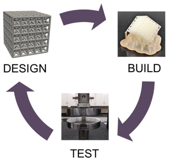
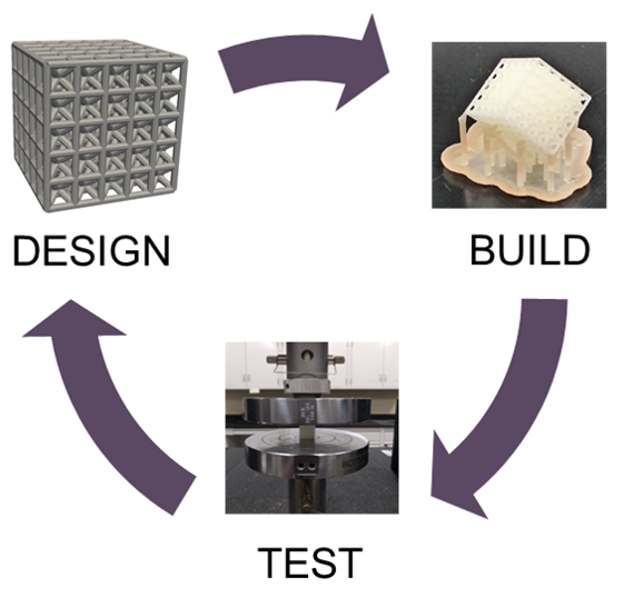
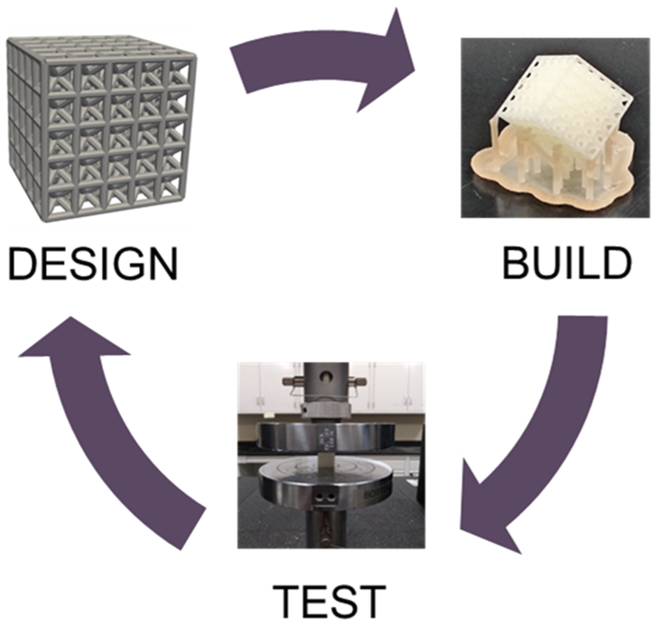
Design approaches often use bio-inspired strategies to match elastic and shear moduli of bone structures with scaffold topologies similar to trabecular bone [20,21]. There is a need for new design approaches to facilitate configuration of tissue scaffolds with clinically suitable functionality, with iteration being necessary for efficient exploration of the design space [22,23]. Therefore, we approach the design space using an iterative design–build–test approach to measure mechanical properties of lattices to determine how design decisions and fabrication influence suitability for bone tissue engineering, as demonstrated in Figure 1.
The Figure 1 approach uses iteration to initially propose a design, then it is fabricated with accuracy validation, and tested to determine lattice behavior. The process provides a basis for understanding how design decisions and fabrication processes influence lattice behavior in model development and optimization for customized lattice applications. Typically, a control structure is fabricated each iteration so design and fabrication influences are compared relative to a known structure’s behavior, which has been conducted with a body-centered (BC) cube topology in previous studies [1]. The process enables efficient testing of specific design decisions, such as rescaling lattices for specified applications from their base properties [24,25], altering topology for favorable elastic/shear modulus trade-offs [26,27,28], and introducing hierarchy for improved porosity and mechanical efficiency [29,30,31,32].
Lattice rescaling is a key design consideration because the repeating material that makes up a lattice’s structures has properties such as elastic modulus that should remain constant as a lattice is patterned with more or less unit cells for a specified application. However, recent studies demonstrate lattice elastic modulus decreases with an increase in unit cell count [24]. Topology design refers to the arrangement of beams or materials throughout a lattice, and is often conducted using optimization approaches due to the complexity of 3D printed lattice design spaces [27,28]. Computational studies have demonstrated that a greater number of beams aligned with the loading direction increases stiffness in that direction, while diagonal beams improve shear modulus [26]. Unit cells with a combination of orthogonal and diagonal beams, such as the octet structure, provide favorable trade-offs when considering elastic and shear moduli in all directions [5]. Bone has a natural hierarchy of small and large pores that has been replicated recently with 3D printed designs using resin-based printing processes [29,32]. Studies have also demonstrated the possibility of tuning such structures to encourage bone tissue growth [30]. Mixing pore sizes combines small pores to encourage tissue seeding and growth with large pores aiding nutrient transport. Exploring these types of design decisions for tissue engineering applications provides a basis for tuning structures for specified application needs.
In this paper, we investigate the how design decisions influence the mechanics of 3D printed lattices fabricated using biocompatible stereolithography. These lattices can be designed as building blocks to construct diverse lattice structures for patient-specific customization. Experiments include initial characterization of the material, resizing lattice structures, topology selection, and hierarchy that could provide more favorable mechanical properties for lattices. The investigation is conducted using a design–build–test approach with BC unit cell lattices used as a datum of comparison. The study is expected to provide an understanding of how design decisions and fabrication influences lattice behavior, while informing future configuration of tissue scaffolds and lattices for diverse engineering applications.
2. Methods
2.1. Lattice Design
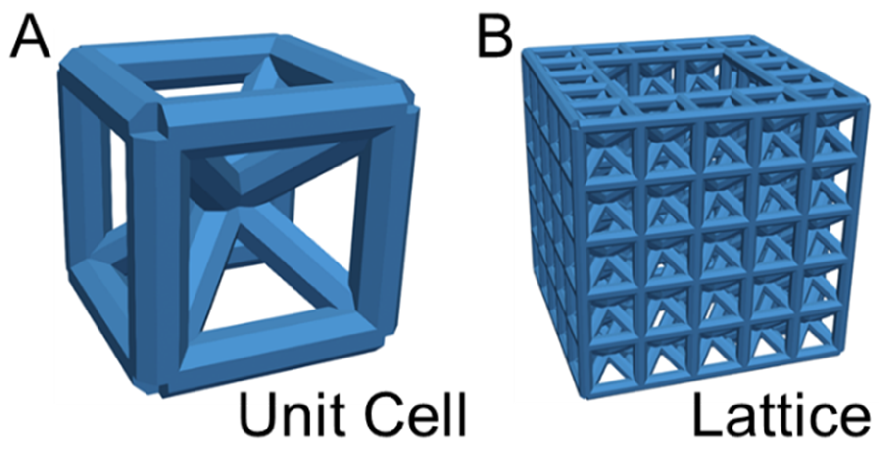
Lattices were designed by configuring unit cells built by connecting beams with octagonal cross-sections to form specified topologies. Unit cells were configured with previously designed topologies to facilitate comparisons with alternate 3D printing processes [13]. Unit cells were then patterned to form architected lattice structures (Figure 2).
Abaqus software was automated with python to configure unit cells based on parameter inputs for beam diameter, unit cell length, and unit cell topology. Beam diameter was always set to 0.8 mm and unit cell length was adjusted until a porosity of approximately 70% was achieved. Unit cells were generated in four different topologies by organizing beam connections in a cubic volume (note: illustrations of all topologies are presented with their associated mechanical testing data in Figure 3 in Results Section 3.3). The cube topology was created by placing beams on all edges of a cubic volume. The BC (body-centered cube) topology was generated by connecting beams from the corners of the cube to its volumetric center as demonstrated in Figure 2A. An FX (face-crossed cube) topology was generated by extending beams from the corners of the cubic volume to the center of each face. The FXBC (face-crossed body-centered cube) topology consisted of the basic cube topology with added diagonal beams from the FX and BC topologies.
Lattices were patterned with a specified number of unit cells in all directions. Void lattices were generated by laying out a cross-sectional pattern of unit cells with a central hole of unit cells; the cross-sectional pattern is then replicated and stacked on top of itself in the vertical direction to form a lattice. In Figure 2B, a BC-Void lattice was formed by creating a layout of 5 × 5 unit cells, removing a 3 × 3 grid in the center, and then stacking the layer of unit cells five times to form a lattice that has a 5 × 5 × 5 configuration with 45 unit cells removed from its central void. A BC-Cage lattice was configured from a 7 × 7 grid with four 2 × 2 holes symmetrically removed that was stacked three unit cells high to form a 7 × 7 × 3 lattice with porosity and dimensions suitable for vertebral fusion applications.
Unit cells are arranged based on beams meeting at the center of their cross-sectional area which leads a minor void area in the corner of each unit cell. Once unit cells are patterned to form lattices, these voids are closed between adjacent unit cells that mitigates their influence on lattice mechanics since the voids are only present on the boundary of the lattices. Since these voids are only present on lattice borders their influence on mechanics is expected to be greater for lattices with a smaller ratio of border to internal unit cells.
2.2. Build Process
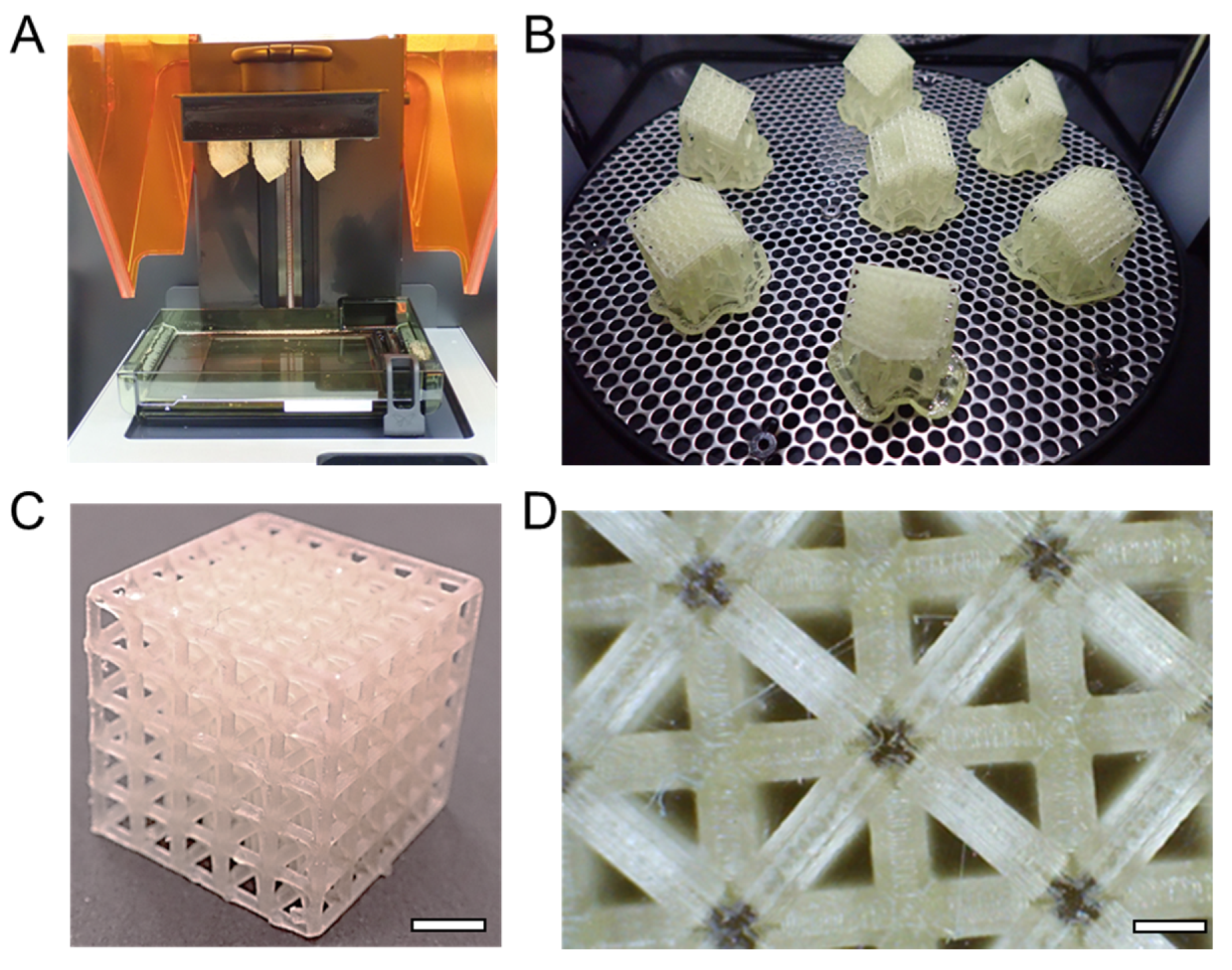
Designed lattices were printed with a stereolithography printing process using direct laser writing (Formlabs; Form 2 printer) with a biocompatible resin composed primarily of methacrylic acid (Formlabs; Dental SG). Lattices were printed layer by layer with initial printing of support material that adhered to the build platform. All lattice prints were fabricated with 50 µm layer thickness. Lattices were placed in a diagonal orientation such that all planes were rotated 45° relative to the build platform (Figure 4A). Therefore, support material was connected to the three planes that faced the build platform and the remaining planes had no support material attachments, meaning the lattice should have similar behavior regardless of testing direction. Printing one set of lattices typically required about five hours of printing time for a build platform containing about eight lattices, however, print time varied based on lattice design and desired number of prints.
Lattices were removed from the build platform using a metal spatula and rinsed in an isopropyl alcohol bath for five minutes (Formlabs; Form Wash). Lattices were placed in an ultraviolet curing chamber (Formlabs; Form Cure) for thirty minutes (Figure 4B). Support material was removed by hand after curing using snipping tools and razor blades followed by sanding rough edges to form a final post-processed print (Figure 4C). Microscopy was used to image select samples and demonstrated consistent printing of beams throughout the structure (Figure 4D). There were some inconstancies observed for samples with broken beams that occurred as a byproduct of support material removal. Lattice fabrication accuracy was measured using calipers for nominal dimensions and a scale to measure weight. Weight measurements were used to calculate porosity by comparing the 1.154 g/cm3 density of the base material determined by printing solid cube samples to the lattice weight for a nominal lattice volume.
2.3. Mechanical Testing
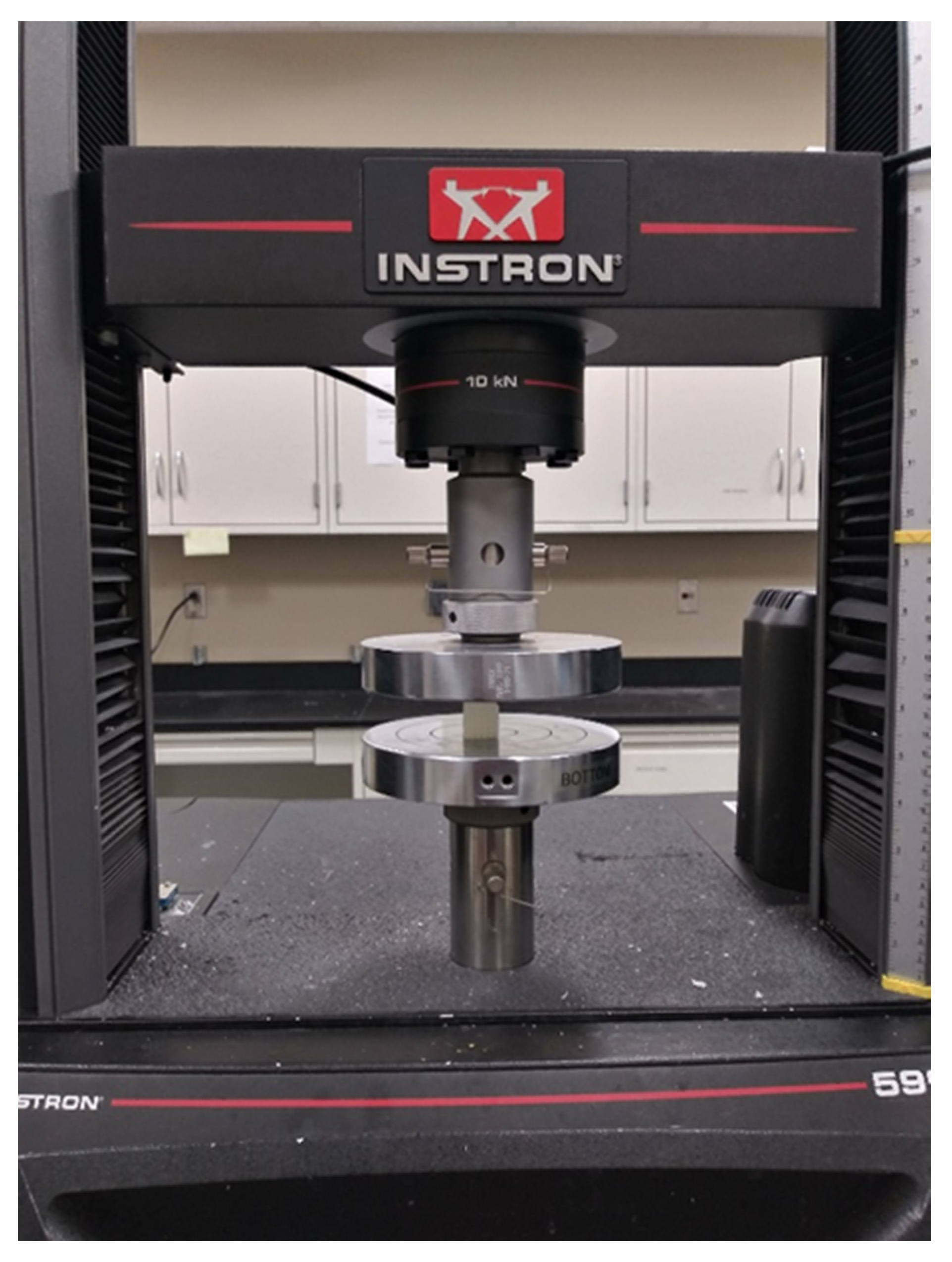
Mechanical testing was conducted using a universal testing machine (Instron; Instron 5966 Universal testing instrument; Norwood, MA, USA) with samples placed on a flat surface between two compression plates (Figure 5). Force-displacement response was recorded using a loading rate of 10% strain per minute for each sample.
For all mechanical tests multiple samples were printed with results averaged for statistical analysis. A minimum of three samples were tested for each condition with a maximum of five when design volume allowed for fitting a larger number of samples on the build plate during printing. All error is reported as the standard error of the mean, with significance between samples determined using t-tests with significance claimed for p ≤ 0.05.
3. Results
3.1. Material Characterization
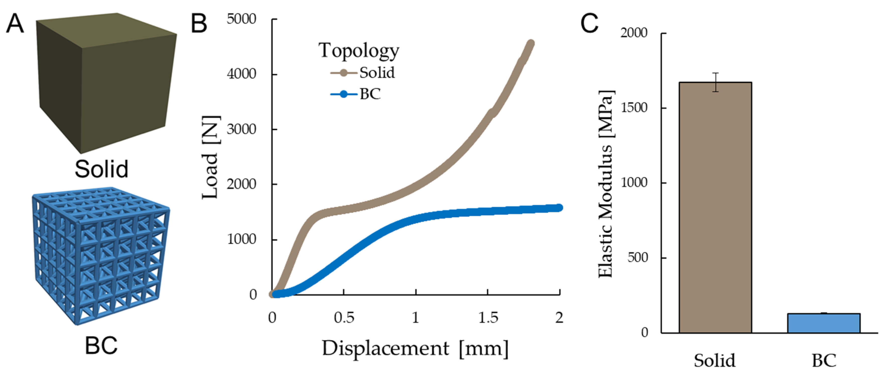
A solid cube of 4 mm was designed and printed with a 5 × 5 × 5 BC lattice to compare how lattice mechanics compare to the base material. Results of design, fabrication, and mechanical testing are presented in Table 1.
The CAD (computer-aided design) models corresponding to Table 1 measurements are presented in Figure 6A and demonstrate a solid structure with no beams for the Solid topology and a BC lattice of 5 × 5 × 5 configuration. The lattice had an 0.05 mm difference in measured length compared to its designed length of 17.3 mm which represents less than a 0.5% difference between CAD and fabricated design. The porosity of the BC lattice was 63% which is lower than its designed 70% porosity, therefore suggesting extra material is added to the design during the printing process. Mechanical properties were calculated from results for the load-displacement curves and elastic moduli plotted in Figure 6B,C, respectively.
The displacement curves demonstrate the solid design carries much greater load per displacement than the BC lattice. The elastic modulus measured for the solid is 1670 MPa and is about 13 times higher than the BC lattice’s elastic modulus of about 130 MPa (p ≤ 0.01).
3.2. Lattice Rescaling
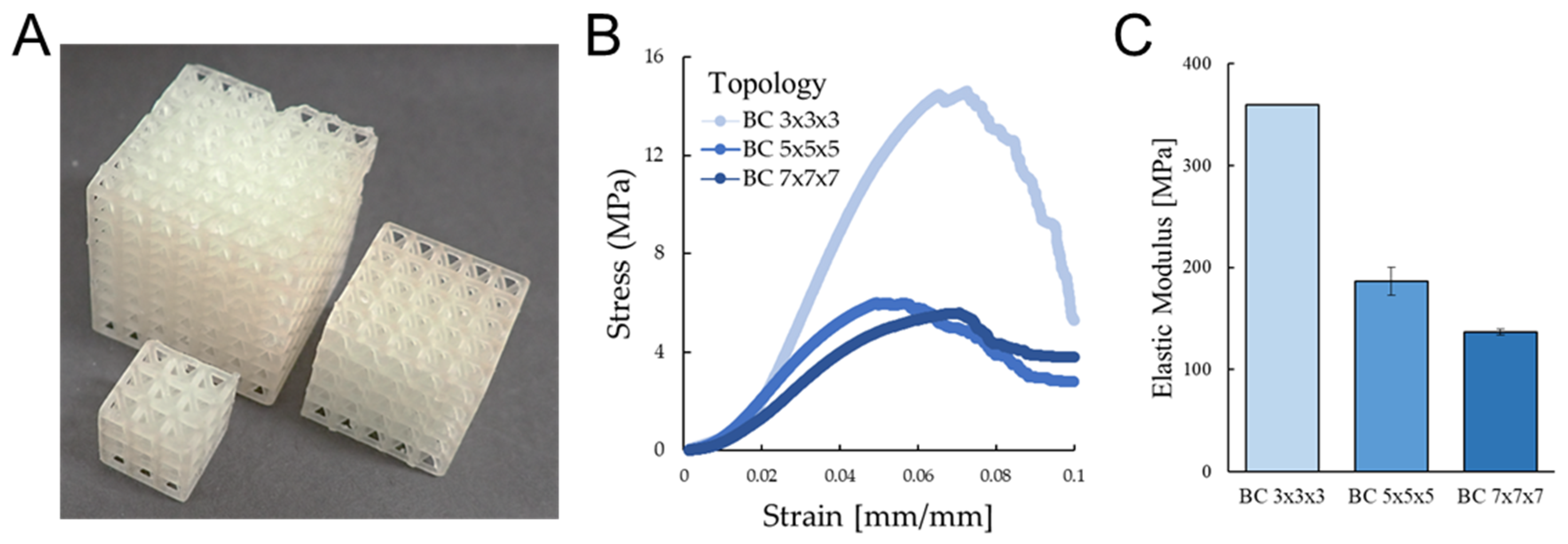
BC lattices were designed with the same unit cell pattered in three different scalings that included a BC 3 × 3 × 3, a BC 5 × 5 × 5, and a BC 7 × 7 × 7 configuration. Results of design, fabrication measurements, and mechanical testing are presented in Table 2.
Lattice fabrication demonstrates similar unit cell structures were achieved for all lattices and they were proportionally different lengths based on the number of unit cells patterned in each lattice (Figure 7A). There were some inconsistencies in beam quality, as demonstrated by the break of the beam on the top plane of the BC 7 × 7 × 7 lattice. Porosity measurements differed with the BC 3 × 3 × 3 lattice having 51% porosity, the BC 5 × 5 × 5 lattice having 58% porosity, and the BC 7 × 7 × 7 lattice having 62% porosity.
The stress–strain curves were plotted for mean measurements of all testing and demonstrated the BC 3 × 3 × 3 lattice achieved the highest yield and ultimate stresses (Figure 7B). The BC 5 × 5 × 5 and BC 7 × 7 × 7 lattices had more similar mechanical behavior, although the BC 5 × 5 × 5 had a 40% higher elastic modulus. The elastic moduli for all topologies are plotted in Figure 7C.
The elastic modulus of the BC 3 × 3 × 3 design was significantly higher than both the BC 5 × 5 × 5 and BC 7 × 7 × 7 designs (p ≤ 0.001) and the BC 5 × 5 × 5 had a significantly higher elastic modulus than the BC 7 × 7 × 7 design (p ≤ 0.024). These differences demonstrate that as the number of unit cells increase in a symmetrically laid out lattice that the elastic modulus decreases. The difference in elastic moduli between designs decreases as a larger number of unit cells are included, as supported by the difference between the BC 3 × 3 × 3 and BC 5 × 5 × 5 design being about 170 MPa and the difference between the BC 5 × 5 × 5 and BC 7 × 7 × 7 design being about 50 MPa. Some of the differences may be attributed to porosity differences, since elastic modulus increases with decreases in porosity, and due to the differing numbers of unit cells on the boundary of each lattice. The different numbers of unit cells on lattice boundaries affects mechanics because these unit cells are subject to different boundary conditions than internal lattice unit cells.
3.3. Unit Cell Topology
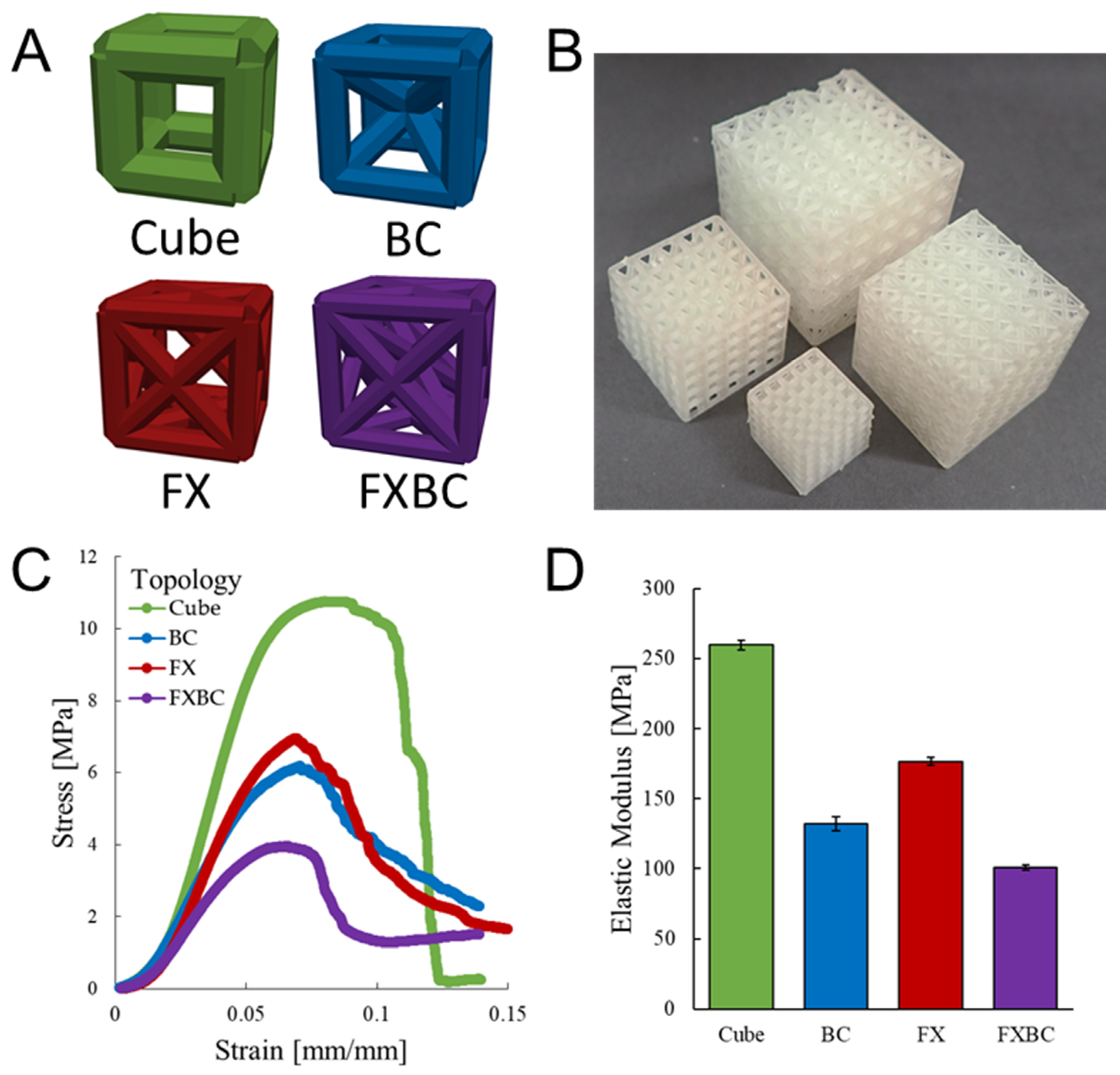
Four cubic unit cell topologies were generated as described in Methods Section 2.1 and include Cube, BC, FX, and FXBC configurations (Figure 3A). Designs were generated as 5 × 5 × 5 lattices with design, fabrication measurement, and mechanical testing results presented in Table 3. The unit cell and lattice length differs for each topology due to the need to resize unit cell length while maintaining a controlled beam diameter to achieve a 70% designed porosity.
Lattice fabrications are presented in Figure 3B and demonstrate the relative size of each lattice to one another with some inconsistencies on beam printing for boundary unit cells. All topologies achieved a porosity of 63% to 68%, therefore suggesting most differences in mechanical performance are attributed to differences in topology. The force-displacement curves and elastic moduli of all topologies are plotted in Figure 3C,D, respectively.
Figure 3 results demonstrate the Cube has the highest elastic modulus, followed by the FX, BC, and lastly FXBC designs. These results suggest the elastic modulus is proportional to the proportion of beams aligned with the loading direction, since the FXBC topology that has the greatest number of diagonal beams per unit volume and the lowest elastic modulus. All pair-wise differences in elastic moduli between topologies were significant (p ≤ 0.01).
3.4. Hierarchical Lattices
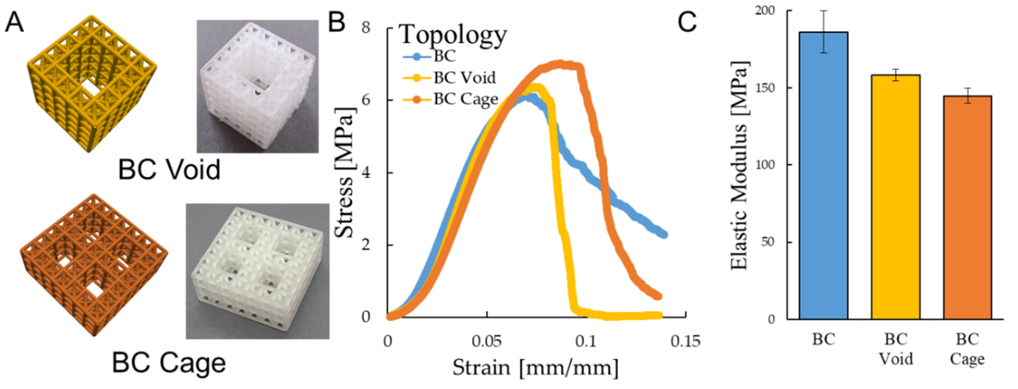
Two hierarchical lattices were designed and tested, with comparisons to a 5 × 5 × 5 BC lattice as a control (Table 4). The hierarchical lattices consisted of a BC-Void configuration that is representative of a building block lattice that could be patterned to form a larger structure. The BC-Cage hierarchical lattice is configured with dimensions suitable for spinal fusion applications. Details on hierarchical lattice generation are presented in Methods: Section 2.1.
Hierarchical designs and fabrications are demonstrated in Figure 3A and show each structure was reliably printed and structurally stable with large voids. Results show that the hierarchical lattices achieved a much higher porosity (71% to 74%) in comparison to the BC lattice (58% porosity) due to the large void spaces from removed unit cells. All designs had similar strain-stress curves (Figure 8B) although elastic moduli ranged from 145 MPa to 186 MPa (Figure 8C).
The differences in elastic modulus of the BC lattice was approximately 30 MPa to 40 MPa higher than hierarchical lattices (p ≤ 0.047 for both cases). The BC-Void and BC-Cage were not significantly different but had a trending difference (p ≤ 0.07), with the BC-Void having about 10 MPa higher elastic modulus than the BC-Cage. This small difference between the BC-Void and BC-Cage design suggests the possibility of patterning varied building blocks with void volumes to form customized lattice structures for specified applications with minimized alterations to mechanics. The stiffness of the BC-Cage was higher than the other lattices due to its greater overall size, and achieved a stiffness of approximately 7.72 kN/mm that is suitable for bone fusion applications.
4. Discussion
This study investigated the mechanics of lattice designs printed using a biocompatible stereolithography process and their potential use as building blocks for biomedical applications. The stereolithography approach is advantageous because it enables economical fabrication of customized medical devices that interface with the human body. A design–build–test methodological approach was used to conduct mechanical experiments and evaluate print accuracy for lattices. Design alterations for testing included comparisons of lattice rescaling, topology, and hierarchy. Results demonstrated lattices achieve stiffnesses suitable for bone tissue engineering and the printing process reliably prints parts with acceptable variations of less than 0.5% for external dimensions compared to designed dimensions.
Initial material characterization demonstrated the methacrylic-acid based polymer used to fabricate lattices had a density of 1.154 g/cm3 and elastic modulus of 1673.5 MPa. The 5 × 5 × 5 BC lattice designed with 70% had a porosity of 63% with an elastic modulus of 132 MPa when compared to the solid cube in Figure 6A. A second batch of 5 × 5 × 5 BC lattices had a porosity of 58% with elastic modulus of 186 MPa for Figure 7 comparisons. These differences in mechanics may be attributed to the differing porosity achieved by each design, since higher porosity designs should have lower elastic moduli due to less material present. The difference in porosity is potentially caused by how lattices were arranged on the build platform for each batch that results in slightly different proportions of deposited material. Additionally, stochastic aspects of printing and storage such as external temperature and humidity may also influence lattice properties. To limit the influence of print quality from different batches on experimental results, two batches were printed for the study and all prints used for comparisons within a given table/figure were printed within the same batch. Each batch consisted of build platforms of lattices printed within a 48-hour duration. Data for Figure 6; Figure 3 were tested from a batch of samples tested three days after printing and data for Figure 7; Figure 8 were tested from a batch of samples tested six days after printing. Generally, a lengthier time after printing results in a slight increase in elastic modulus for polymer 3D printing [1].
As lattice designs are readjusted with an increased number of unit cells, the elastic modulus of the lattice is expected to decrease based on the differing proportions of boundary to internal unit cells. Previous studies for a stereolithography process demonstrated lattice elastic modulus dropped from 350 MPa to 250 MPa when comparing a 3 × 3 × 3 to 7 × 7 × 7 lattice [24]. Here, the same comparison resulted in elastic modulus dropping from 360 MPa to 140 MPa, which is qualitatively similar but occurs at a much greater magnitude. These differences may be because the 3 × 3 × 3 lattice tested here had a lower porosity than the 7 × 7 × 7 lattice in comparison to the previous study, therefore suggesting print consistency plays a role in how material properties scale for redesigns.
Topology design suggests that a greater number of beams aligned with the loading direction should result in a higher elastic modulus, which was supported by Figure 3 results demonstrating that the Cube had the highest elastic modulus followed by the BC, FX, and FXBC designs. These results are supported when comparing mechanical testing results with a previously developed simulation to model lattice mechanics with finite element analysis details provided by Egan et al. [26]. Briefly, the finite element analysis is carried out by constructing structures formed from beams with each beam behavior approximated with the Euler–Bernouli beam theorem. The elastic moduli predicted by the finite element beam simulation suggests the elastic modulus of the topologies should be 241.7 MPa for the cube, 139.90 MPa for the BC, 142.2 MPa for the FX, and 105.1 MPa for the FXBC topologies, which is consistent with empirical measurements in this study. The simulation operated by predicting the relative elastic modulus of each topology in a 5 × 5 × 5 configuration and multiplying by the measured elastic modulus of the solid material measured in Figure 6. When comparing simulation to empirical results, the FX cube has the greatest discrepancy with an elastic modulus about 30 MPa higher than predicted, which suggests mechanical behavior may be occurring during these tests not captured by the model. These results demonstrate that the stereolithography process is more consistent in producing mechanically functional lattices in comparison to polyjet processes that greatly deviate from simulation results [13], especially for Cube topology.
The BC unit cell was configured to form building blocks for hierarchical lattices to determine mechanical suitability for tissue engineering applications. The introduction of the hierarchical void resulted in a decrease in elastic modulus of 15% while providing an increase in porosity of 17%. When the hierarchical structure was patterned as a spinal cage device it achieved a stiffness of 7.72 kN/mm that is comparable to topology optimized laser-sintered cages and resin-based printing process that achieved stiffnesses of 7.5 kN/mm and 8.9 kN/mm, respectively for similarly sized cages [1,33]. Polymer cages are mechanically advantageous to titanium cages that have about 30 kN/mm stiffness for similarly sized designs and induce stress-shielding resulting in weaker bone growth. The properties of the cage are further tunable through patient-specific sizing and configuring alternative topologies to the BC design.
Limitations in the study include the inconsistency in prints due to the stochastic nature of 3D printing and the limited number of samples based on the time required to print each set of prints to ensure batch testing is consistent. Higher-cost stereolithography machines could potentially print more consistent designs at a faster rate, however, for many biomedical applications lower cost printers may be used in hospitals locally, especially in low-economic areas. Improvements from higher-cost machines include a higher resolution achieved, although achievable limits in resolution remain constrained by material choice and physical limits in processing printing materials to form solid structures. Despite fabrication inconsistences and low numbers of prints for mechanical testing, statistical significance was obtained for hypothesis testing for rescaling, topology, and hierarchy comparisons for mechanical properties.
Future work may consider further types of lattice designs and unit cell configurations, in addition to biological testing of lattices for tissue engineering applications. Lattices demonstrated a variety of failure mechanisms including layer-by-layer failures, shear failures on a 45° diagonal across the lattice, and failures initiated by localized cracks/deformations that could be investigated further in future studies. The presence of small voids on unit cell corners was assumed to have negligible effects on mechanics based on limitations in the experimental design to detect their influence, however, further work could investigate isolating whether these and other manufacturing artifacts have significant effects on mechanical behavior. Optimization processes may also improve the performance of designs by customizing them for specific application needs. This study provides a foundation for future work by empirically demonstrating how design decisions affect lattice mechanical performance and producing a proof-of-concept spinal cage device mechanically suitable for spinal fusion applications.
5. Conclusions
This study investigated the mechanical feasibility of biocompatible stereolithography lattices using a design–build–test approach for compression experiments. Results demonstrate lattices were consistently printed with 5% to 10% porosity lower than their intended porosity of 70% for most designs. Rescaling of lattices decreased elastic moduli with greater numbers of unit cells, however these effects were reduced as total number of unit cells increased. The cube unit cell topology achieved the greatest elastic modulus of 260 MPa in comparison to topologies with greater proportions of diagonal beams with 101 MPa to 176 MPa elastic moduli. The introduction of large porous voids reduced elastic modulus from 186 MPa to 158 MPa with an increase in porosity of 17% that is favorable for tissue engineering. A hierarchical BC-Cage design achieved a 7.72 kN/mm stiffness that is comparable to designs printed with alternate polymer 3D printing approaches for bone fusion. These results reveal the mechanical capabilities of biocompatible stereolithography and provide a basis for further studies investigating the design and fabrication of lattice building blocks for complex 3D printed parts.
Author Contributions
Conceptualization, M.M., C.O., A.B., and P.F.E.; data curation, M.M. and P.F.E.; formal analysis, M.M.; investigation, M.M. and C.O.; methodology, M.M., C.O., A.B., and P.F.E.; software, P.F.E.; validation, M.M. and P.F.E.; resources, P.F.E.; project administration, P.F.E. supervision, A.B. and P.F.E.; writing—original draft preparation, M.M. and P.F.E.; writing—review and editing, M.M., C.O., A.B., and P.F.E. All authors have read and agreed to the published version of the manuscript.
Funding
This research received no external funding.
Conflicts of Interest
The authors declare no conflicts of interest.
References
- Egan, P.F.; Bauer, I.; Shea, K.; Ferguson, S.J. Mechanics of Three-Dimensional Printed Lattices for Biomedical Devices. J. Mech. Des. 2019, 141, 031703. [Google Scholar] [CrossRef]
- Kang’iri, S.; Gradl, C.; Byiringiro, J.; Ngetha, H. Design and Calibration of a 3D-Printed Cup-Vane Wireless Sensor Node. Designs 2018, 2, 21. [Google Scholar] [CrossRef] [Green Version]
- Goulas, A.; Zhang, S.; Cadman, D.A.; Järveläinen, J.; Mylläri, V.; Whittow, W.G.; Vardaxoglou, J.Y.C.; Engstrøm, D.S. The impact of 3D printing process parameters on the dielectric properties of high permittivity composites. Designs 2019, 3, 50. [Google Scholar] [CrossRef] [Green Version]
- Dong, G.; Tang, Y.; Zhao, Y.F. A Survey of Modeling of Lattice Structures Fabricated by Additive Manufacturing. J. Mech. Des. 2017, 139, 100906. [Google Scholar] [CrossRef]
- Ling, C.; Cernicchi, A.; Gilchrist, M.D.; Cardiff, P. Mechanical behaviour of additively-manufactured polymeric octet-truss lattice structures under quasi-static and dynamic compressive loading. Mater. Des. 2019, 162, 106–118. [Google Scholar] [CrossRef]
- Zheng, X.; Lee, H.; Weisgraber, T.H.; Shusteff, M.; DeOtte, J.; Duoss, E.B.; Kuntz, J.D.; Biener, M.M.; Ge, Q.; Jackson, J.A. Ultralight, ultrastiff mechanical metamaterials. Science 2014, 344, 1373–1377. [Google Scholar] [CrossRef] [PubMed] [Green Version]
- Ashby, M. The properties of foams and lattices. Philos. Trans. R. Soc. A Math. Phys. Eng. Sci. 2006, 364, 15–30. [Google Scholar] [CrossRef] [PubMed]
- Egan, P.F. Integrated Design Approaches for 3D Printed Tissue Scaffolds: Review and Outlook. Materials 2019, 12, 2355. [Google Scholar] [CrossRef] [PubMed] [Green Version]
- Langer, R.; Vacanti, J. Tissue engineering. Tissue Eng. Union Biol. Eng. 1993, 98, 920–926. [Google Scholar] [CrossRef] [Green Version]
- Yang, S.; Leong, K.-F.; Du, Z.; Chua, C.-K. The design of scaffolds for use in tissue engineering. Part II. Rapid prototyping techniques. Tissue Eng. 2002, 8, 1–11. [Google Scholar] [CrossRef] [Green Version]
- Leong, K.; Cheah, C.; Chua, C. Solid freeform fabrication of three-dimensional scaffolds for engineering replacement tissues and organs. Biomaterials 2003, 24, 2363–2378. [Google Scholar] [CrossRef]
- Yeong, W.-Y.; Chua, C.-K.; Leong, K.-F.; Chandrasekaran, M. Rapid prototyping in tissue engineering: Challenges and potential. TRENDS Biotechnol. 2004, 22, 643–652. [Google Scholar] [CrossRef] [PubMed]
- Egan, P.; Wang, X.; Greutert, H.; Shea, K.; Wuertz-Kozak, K.; Ferguson, S. Mechanical and Biological Characterization of 3D Printed Lattices. 3D Print. Addit. Manuf. 2019, 6, 73–81. [Google Scholar] [CrossRef]
- Melchels, F.P.; Bertoldi, K.; Gabbrielli, R.; Velders, A.H.; Feijen, J.; Grijpma, D.W. Mathematically defined tissue engineering scaffold architectures prepared by stereolithography. Biomaterials 2010, 31, 6909–6916. [Google Scholar] [CrossRef] [PubMed] [Green Version]
- Alifui-Segbaya, F.; Varma, S.; Lieschke, G.J.; George, R. Biocompatibility of Photopolymers in 3D Printing. 3D Print. Addit. Manuf. 2017, 4, 185–191. [Google Scholar] [CrossRef] [Green Version]
- Rong, Z.; Zeng, W.; Kuang, Y.; Zhang, J.; Liu, X.; Lu, Y.; Cheng, X. Enhanced bioactivity of osteoblast-like cells on poly (lactic acid)/poly (methyl methacrylate)/nano-hydroxyapatite scaffolds for bone tissue engineering. Fibers Polym. 2015, 16, 245–253. [Google Scholar] [CrossRef]
- Pepelanova, I.; Kruppa, K.; Scheper, T.; Lavrentieva, A. Gelatin-Methacryloyl (GelMA) hydrogels with defined degree of functionalization as a versatile toolkit for 3D cell culture and extrusion bioprinting. Bioengineering 2018, 5, 55. [Google Scholar] [CrossRef] [Green Version]
- Byrne, D.P.; Lacroix, D.; Planell, J.A.; Kelly, D.J.; Prendergast, P.J. Simulation of tissue differentiation in a scaffold as a function of porosity, Young’s modulus and dissolution rate: Application of mechanobiological models in tissue engineering. Biomaterials 2007, 28, 5544–5554. [Google Scholar] [CrossRef]
- An, J.; Teoh, J.E.M.; Suntornnond, R.; Chua, C.K. Design and 3D printing of scaffolds and tissues. Engineering 2015, 1, 261–268. [Google Scholar] [CrossRef] [Green Version]
- Sanyal, A.; Gupta, A.; Bayraktar, H.H.; Kwon, R.Y.; Keaveny, T.M. Shear strength behavior of human trabecular bone. J. Biomech. 2012, 45, 2513–2519. [Google Scholar] [CrossRef] [Green Version]
- Barba, D.; Alabort, E.; Reed, R. Synthetic bone: Design by additive manufacturing. Acta Biomater. 2019, 97, 637–656. [Google Scholar] [CrossRef] [PubMed]
- Kengla, C.; Renteria, E.; Wivell, C.; Atala, A.; Yoo, J.J.; Lee, S.J. Clinically Relevant Bioprinting Workflow and Imaging Process for Tissue Construct Design and Validation. 3D Print. Addit. Manuf. 2017, 4, 239–247. [Google Scholar] [CrossRef]
- Hollister, S.J.; Flanagan, C.L.; Zopf, D.A.; Morrison, R.J.; Nasser, H.; Patel, J.J.; Ebramzadeh, E.; Sangiorgio, S.N.; Wheeler, M.B.; Green, G.E. Design control for clinical translation of 3D printed modular scaffolds. Ann. Biomed. Eng. 2015, 43, 774–786. [Google Scholar] [CrossRef] [PubMed]
- Briguiet, G.; Egan, P. Structure, process, and material influences for 3D printed lattices designed with mixed unit cells. In Proceedings of the ASME International Design Engineering Technical Conference, St. Louis, MO, USA, 16–29 August 2020. [Google Scholar]
- Cui, H.; Hensleigh, R.; Chen, H.; Zheng, X. Additive Manufacturing and size-dependent mechanical properties of three-dimensional microarchitected, high-temperature ceramic metamaterials. J. Mater. Res. 2018, 33, 360–371. [Google Scholar] [CrossRef] [Green Version]
- Egan, P.F.; Gonella, V.C.; Engensperger, M.; Ferguson, S.J.; Shea, K. Computationally designed lattices with tuned properties for tissue engineering using 3D printing. PLoS ONE 2017, 12, e0182902. [Google Scholar] [CrossRef] [PubMed]
- Wang, X.; Xu, S.; Zhou, S.; Xu, W.; Leary, M.; Choong, P.; Qian, M.; Brandt, M.; Xie, Y.M. Topological design and additive manufacturing of porous metals for bone scaffolds and orthopaedic implants: A review. Biomaterials 2016, 83, 127–141. [Google Scholar] [CrossRef] [PubMed]
- Liu, C.; Du, Z.; Zhang, W.; Zhu, Y.; Guo, X. Additive manufacturing-oriented design of graded lattice structures through explicit topology optimization. J. Appl. Mech. 2017, 84, 081008. [Google Scholar] [CrossRef]
- Meza, L.R.; Zelhofer, A.J.; Clarke, N.; Mateos, A.J.; Kochmann, D.M.; Greer, J.R. Resilient 3D hierarchical architected metamaterials. Proc. Natl. Acad. Sci. USA 2015, 112, 11502–11507. [Google Scholar] [CrossRef] [Green Version]
- Maggi, A.; Li, H.; Greer, J.R. Three-Dimensional nano-architected scaffolds with tunable stiffness for efficient bone tissue growth. Acta Biomater. 2017, 63, 294–305. [Google Scholar] [CrossRef] [Green Version]
- Ma, Q.; Cheng, H.; Jang, K.-I.; Luan, H.; Hwang, K.-C.; Rogers, J.A.; Huang, Y.; Zhang, Y. A nonlinear mechanics model of bio-inspired hierarchical lattice materials consisting of horseshoe microstructures. J. Mech. Phys. Solids 2016, 90, 179–202. [Google Scholar] [CrossRef] [Green Version]
- Egan, P.; Ferguson, S.; Shea, K. Design of hierarchical 3D printed scaffolds considering mechanical and biological factors for bone tissue engineering. J. Mech. Des. 2017, 139, 061401-1–061401-9. [Google Scholar] [CrossRef]
- Kang, H.; Lin, C.-Y.; Hollister, S.J. Topology optimization of three dimensional tissue engineering scaffold architectures for prescribed bulk modulus and diffusivity. Struct. Multidiscip. Optim. 2010, 42, 633–644. [Google Scholar] [CrossRef]
Figure 1.
Design–build–test process for investigating 3D printed lattice mechanics.

Figure 2.
Example design for (A) a body-centered (BC) unit cell and (B) a BC-Void lattice built from BC unit cells.
Figure 2.
Example design for (A) a body-centered (BC) unit cell and (B) a BC-Void lattice built from BC unit cells.

Figure 3.
Topologies including (A) Cube, body-centered (BC), face-crossed (FX), and face-crossed body-centered (FXBC) unit cells with resulting (B) fabrications, (C) stress-strain curves, and (D) elastic moduli measurements.
Figure 3.
Topologies including (A) Cube, body-centered (BC), face-crossed (FX), and face-crossed body-centered (FXBC) unit cells with resulting (B) fabrications, (C) stress-strain curves, and (D) elastic moduli measurements.

Figure 4.
Build process for lattices (A) printed with support material on build platform, (B) in an ultraviolet curing chamber, (C) after post-processing (5 mm scale bar), and (D) imaged with microscopy (1 mm scale bar).
Figure 4.
Build process for lattices (A) printed with support material on build platform, (B) in an ultraviolet curing chamber, (C) after post-processing (5 mm scale bar), and (D) imaged with microscopy (1 mm scale bar).

Figure 5.
Mechanical testing machine configured for lattice compression.

Figure 6.
Material characterization for (A) Solid and BC lattice topologies, (B) their load-displacement curves, and (C) elastic moduli.
Figure 6.
Material characterization for (A) Solid and BC lattice topologies, (B) their load-displacement curves, and (C) elastic moduli.

Figure 7.
Rescaling of BC cube lattice showing fabrications for (A) BC cube 3 × 3 × 3, BC cube 5 × 5 × 5, and BC cube 7 × 7 × 7 lattice topologies, (B) stress–strain curves, and (C) elastic moduli.
Figure 7.
Rescaling of BC cube lattice showing fabrications for (A) BC cube 3 × 3 × 3, BC cube 5 × 5 × 5, and BC cube 7 × 7 × 7 lattice topologies, (B) stress–strain curves, and (C) elastic moduli.

Figure 8.
CAD designs and fabrications for (A) BC-Void and BC-Cage designs with (B) stress–strain curves, and (C) elastic moduli measurements when compared to BC 5 × 5 × 5 lattices.
Figure 8.
CAD designs and fabrications for (A) BC-Void and BC-Cage designs with (B) stress–strain curves, and (C) elastic moduli measurements when compared to BC 5 × 5 × 5 lattices.


Table 1.
Design and measurements for material characterization.
| Topology | Designed | Measured Data | ||||
|---|---|---|---|---|---|---|
| Beam Diameter | Cell Length | Lattice Length | Lattice Length | Porosity | Elastic Modulus | |
| (mm) | (mm) | (mm) | (mm) | (%) | (MPa) | |
| Solid | 0.8 | 4 | 4 | 4.11 | 0 | 1673.5 |
| ± 0.01 | ± 0 | ± 62.7 | ||||
| BC | 0.8 | 3.3 | 17.3 | 17.35 | 63.1 | 132 |
| ± 0.02 | ± 0.38 | ± 4.9 | ||||
Table 2.
Design and measurements for rescaled lattices.
| Topology | Designed | Measured Data | |||||||
|---|---|---|---|---|---|---|---|---|---|
| Beam Diameter | Cell Length | Lattice Length | Lattice Length | Porosity | Elastic Modulus | Yield Stress | Yield Strain | Ultimate Strength | |
| (mm) | (mm) | (mm) | (mm) | (%) | (MPa) | (MPa) | (-) | (MPa) | |
| BC 3 × 3 × 3 | 0.8 | 3.3 | 10.7 | 10.92 | 50.69 | 359.8 | 11.8 | 0.05 | 14.8 |
| ± 0.02 | ± 0.33 | ± 0.5 | ± 0.1 | ± 0.001 | ± 0.2 | ||||
| BC 5 × 5 × 5 | 0.8 | 3.3 | 17.3 | 17.39 | 57.68 | 186.1 | 5.1 | 0.04 | 6.2 |
| ± 0.05 | ± 3.74 | ± 13.7 | ± 0.2 | ± 0.003 | ± 0.3 | ||||
| BC 7 × 7 × 7 | 0.8 | 3.3 | 23.9 | 23.95 | 61.52 | 136.7 | 4.5 | 0.04 | 5.6 |
| ± 0.03 | ± 0.27 | ± 2.8 | ± 0.1 | ± 0.08 | ± 0.1 | ||||
Table 3.
Design and measurements for unit cell topologies.
| Topology | Designed | Measured Data | |||||||
|---|---|---|---|---|---|---|---|---|---|
| Beam Diameter | Cell Length | Lattice Length | Lattice Length | Porosity | Elastic Modulus | Yield Stress | Yield Strain | Ultimate Strength | |
| (mm) | (mm) | (mm) | (mm) | (%) | (MPa) | (MPa) | (-) | (MPa) | |
| Cube | 0.8 | 2.16 | 11.60 | 11.63 | 67.91 | 259.6 | 9.2 | 0.050 | 10.8 |
| ± 0.02 | ± 0.55 | ± 3.4 | ± 0.3 | ± 0.002 | ± 0.4 | ||||
| BC | 0.8 | 3.30 | 17.30 | 17.35 | 63.07 | 132.0 | 5.3 | 0.050 | 6.3 |
| ± 0.02 | ± 0.38 | ± 4.9 | ± 0.2 | ± 0.001 | ± 0.2 | ||||
| FX | 0.8 | 3.97 | 20.65 | 20.71 | 65.24 | 176.4 | 5.6 | 0.050 | 7.1 |
| ± 0.02 | ± 0.35 | ± 2.8 | ± 0.1 | ± 0.002 | ± 0.2 | ||||
| FXBC | 0.8 | 4.84 | 25.00 | 25.03 | 64.20 | 101.0 | 3.3 | 0.050 | 4.1 |
| ± 0.02 | ± 0.11 | ± 1.9 | ± 0.1 | ± 0.001 | ± 0.1 | ||||
Table 4.
Design and measurements for hierarchical lattices.
| Topology | Designed | Measured Data | ||||||||
|---|---|---|---|---|---|---|---|---|---|---|
| Beam Diameter | Cell Length | Lattice Length | Lattice Length | Porosity | Elastic Modulus | Yield Stress | Yield Strain | Ultimate Strength | Stiffness | |
| (mm) | (mm) | (mm) | (mm) | (%) | (Mpa) | (Mpa) | (-) | (MPa) | (kN/mm) | |
| BC | 0.8 | 3.3 | 17.3 | 17.39 | 57.68 | 186.1 | 5.1 | 0.040 | 6.2 | 3.22 |
| ± 0.05 | ± 3.74 | ± 13.7 | ± 0.2 | ± 0.003 | ± 0.3 | ± 0.24 | ||||
| BC-Void | 0.8 | 3.3 | 17.3 | 17.31 | 74.86 | 158.2 | 5.3 | 0.050 | 6.5 | 2.74 |
| ± 0.02 | ± 1.33 | ± 3.8 | ± 0.1 | ± 0.001 | ± 0.1 | ± 0.07 | ||||
| BC-Cage | 0.8 | 3.3 | 23.9 | 23.90 | 71.02 | 144.7 | 5.7 | 0.050 | 7.1 | 7.72 |
| ± 0.02 | ± 0.22 | ± 4.8 | ± 0.2 | ± 0.006 | ± 0.1 | ± 0.26 | ||||
© 2020 by the authors. Licensee MDPI, Basel, Switzerland. This article is an open access article distributed under the terms and conditions of the Creative Commons Attribution (CC BY) license (http://creativecommons.org/licenses/by/4.0/).
Share and Cite
MDPI and ACS Style
Moniruzzaman, M.; O'Neal, C.; Bhuiyan, A.; Egan, P.F. Design and Mechanical Testing of 3D Printed Hierarchical Lattices Using Biocompatible Stereolithography. Designs 2020, 4, 22. https://0-doi-org.brum.beds.ac.uk/10.3390/designs4030022
AMA Style
Moniruzzaman M, O'Neal C, Bhuiyan A, Egan PF. Design and Mechanical Testing of 3D Printed Hierarchical Lattices Using Biocompatible Stereolithography. Designs. 2020; 4(3):22. https://0-doi-org.brum.beds.ac.uk/10.3390/designs4030022
Chicago/Turabian StyleMoniruzzaman, Md, Christopher O'Neal, Ariful Bhuiyan, and Paul F. Egan. 2020. "Design and Mechanical Testing of 3D Printed Hierarchical Lattices Using Biocompatible Stereolithography" Designs 4, no. 3: 22. https://0-doi-org.brum.beds.ac.uk/10.3390/designs4030022