A Novel Digital Design Approach for Metal Additive Manufacturing to Address Local Thermal Effects


1
Theoretical & Applied Mechanics Group, Mechanical Engineering & Mechanics Department, Drexel University, 3141 Chestnut Street, Philadelphia, PA 19104, USA
2
Multiscale Computational Mechanics and Biomechanics LAB, Mechanical Engineering & Mechanics Department, Drexel University, 3141 Chestnut Street, Philadelphia, PA 19104, USA
*
Authors to whom correspondence should be addressed.
Designs 2020, 4(4), 41; https://0-doi-org.brum.beds.ac.uk/10.3390/designs4040041
Submission received: 21 August 2020
/
Revised: 23 September 2020
/
Accepted: 24 September 2020
/
Published: 1 October 2020
Abstract
:The reliability and performance qualification of additively manufactured metal parts is critical for their successful and safe use in engineering applications. In current powder-bed fusion type metal additive manufacturing processes, local thermal accumulations affect material microstructure features, overall part quality and integrity, as well as bulk mechanical behavior. To address such challenges, the investigation presented in this manuscript describes a novel digital design approach combining topology optimization, process simulations, and lattice size optimization to address local thermal effects caused during manufacturing. Specifically, lattices are introduced in regions of topology optimized geometries where local thermal accumulations are predicted using the process simulations with the overall goal to mitigate high thermal gradients. The results presented demonstrate that the proposed digital design approach reduces local thermal accumulations while achieving target mechanical performance metrics. A discussion on how post-manufacturing heat treatment effects could be also considered, as well as comments on the computational implementation of the proposed approach are provided.
1. Introduction
Metal additive manufacturing (AM) holds a great promise for engineering applications, e.g., in the aerospace and biomedical industries. The ability of metal AM to produce complex material structures [1,2] helps address issues of part consolidation and weight reduction, for example in the aerospace industry [3,4]. In doing so, AM can positively disrupt current supply chain and sustainability models [5], while also achieving improvements of mechanical performance. For the biomedical industry, AM further allows for patient specific design of implants, incorporation of porosity to mitigate stress shielding [6] and surface modification for better implant-tissue integration [7]. In the context of AM, 3D-architected cellular materials such as lattices have become viable options for manufacturing. This new class of manufactured materials enable control of material properties at several length scales, while achieving target macroscale properties such as specific strength and stiffness that are not achievable with existing metals, alloys, or composites. [8,9]. Lattices have also been found to have superior thermal and impact dissipation properties compared to corresponding solid geometries, thus making them a great choice for multifunctional applications [10,11].
There are several different techniques of producing metal parts using AM processes with the most well-known being powder bed fusion (PBF) and direct energy deposition (DED) [12,13]. PBF methods are the most widely adopted because of their capability to achieve tolerances in the micrometer range and to produce complex geometries in near net shape [14]. The PBF methods are, however, limited by the range of materials that can be used for a single print, since the part and the supporting structure around it are built from the same material. In comparison, DED parts are capable of multi-metal fabrication using multiple nozzles delivering different metals that achieve an in-situ alloyed material [15]. The part tolerances achieved with DED, however, are coarser and therefore this method is preferred when fabricating bulk parts with relatively simple geometries. PBF methods, however, have shown to produce metals with higher yield strength values compared to DED [16]. All these factors make PBF methods a preferred AM approach to creating functional parts with sizes below 200 mm width or breadth and height below 300 mm.
The advantage of AM is best realized when coupled with design optimization techniques such as topology optimization (TO) and shape optimization (SO) that allow for highly optimized geometries for a given set of performance objectives, constraints, and boundary conditions. Currently significant progress has been made to compute TO outcomes that are manufacturing-ready. Algorithms have been developed to create self-supporting topology optimization outputs [17,18] or optimize the build orientation [19], as removing support structures from intricate geometries is cumbersome and can cause the final part to deviate from the optimal design. In this context, hybrid manufacturing schemes have been developed to account for such post-processing requirements for selective laser melting (SLM) printing [20,21]. In addition, lattice design has also been incorporated into topology optimization schemes to reduce weight of bulky metallic parts while maintaining, e.g. their specific stiffness [22]. However, there are many instances reported where the printed part is considerably different than the optimal solution as given by topology optimization. This is in part due to the thermal stresses that build up during manufacturing and cause distortions of the produced part. In other cases, uncertainties related to the feedstock material quality lead to unexpected print outcomes. In fact, AM lattices are prone to contain defects such as dimensional inaccuracies and strut waviness [23]. Due to these reasons, topology optimization that also addresses manufacturing uncertainties has been an area of active research [24,25]. A detailed review of the optimization techniques for AM has been carried out by Liu et al. [26].
In spite of the promise that metal AM methods hold, they also have some significant shortcomings due to the high thermal gradients caused by the use of high energy sources during fabrication, which result in distortions caused by accumulated residual stresses and nonhomogeneous material characteristics (e.g., porosity, texture, grain size) created by local material evaporation [27,28]. These issues affect the overall performance of AM parts and create challenges in the process to meet the appropriate product qualification criteria. Specifically, for PBF methods such as selective laser melting (SLM), local thermal accumulations, also referred to as thermal hotspots, constitute an important manufacturing concern. Such thermal hotspots affect the local material properties leading to uncontrolled, spatially-gradient properties throughout the final part geometry [29]. Material regions with such local heat accumulations further experience grain nucleation and growth for longer periods, leading to different crystalline properties than the surrounding regions [30,31]. This also leads to residual stresses that lead to part distortions and manufacturing-induced failure sites at the structural scale. For a complex part the effect of local thermal accumulation may be more pronounced in the form of distortion of fins and ribs connected to a solid body [32], deflection normal to height [33] that can interfere with the powder recoater movement and in some cases, the part may crack or break on removing the part from the build plate itself [34].
Thermal hotspots follow sites of heat accumulation which result in local temperatures exceeding the evaporation temperature of the feedstock material. The most straightforward approach to address such thermal accumulations would be to reduce the heat input induced by the laser power. This approach, however, causes the detrimental effect of localized regions experiencing incomplete powder fusion and result in lack of fusion pores [35]. Such a scenario occurs when the temperature in a given additively manufactured region is below the solidus temperature of the alloy. Currently lack of fusion pores are reduced by hot isostatic pressing (HIP), however Zhang et al. [36] reported that this approach deforms the lack of fusion pores which form slit-shaped crevices in the order of hundreds of nanometers, and thus effectively become incubation sites for damage. An alternative approach would be to use the support structures as a heat conduit, to direct part of the heat from the part to the base plate [37]. However, this method is limited by the accessibility of the thermal hotspot region with respect to the base plate. Another approach would be to include local thermal accumulations as a constraint in the computational optimization design stage and execute a coupled thermomechanical topology optimization as described by Ranjan et al. [38]. However, this method has only been implemented for 2D scenarios and, therefore, scaling it up to complex 3D domains will be computationally expensive. In this context, lattices have been shown to dissipate heat to the surrounding environment by convection [39]. As a result, some optimization methods have been developed to incorporate lattices in design optimization to produce multifunctional structures to optimize heat dissipation while providing increased specific stiffness [40,41]. These methods, however, leverage the multifunctionality offered by the lattice design only after the print process has been completed and therefore limit their positive effects.
The objective of the investigation reported in this manuscript is to address local thermal accumulations observed in metal AM by selectively introducing architected material regions and specifically lattices exactly in areas predicted by thermomechanical process simulations to experience such thermal effects. This approach is executed by using a combination of available design tools to enable its practical use in metal AM. Hence, we propose a digital design methodology that combines topology and lattice optimization approaches to produce material volumes that have a priori better chances to not suffer from local thermal effects in metal AM. Finally, the investigation discusses the manufacturing feasibility of such AM parts with optimized geometries and discusses computational, analysis and fabrication challenges to achieve this goal.
2. Design Approach Overview
2.1. Digital Design Approach for Metal AM That Addresses Thermal Effects
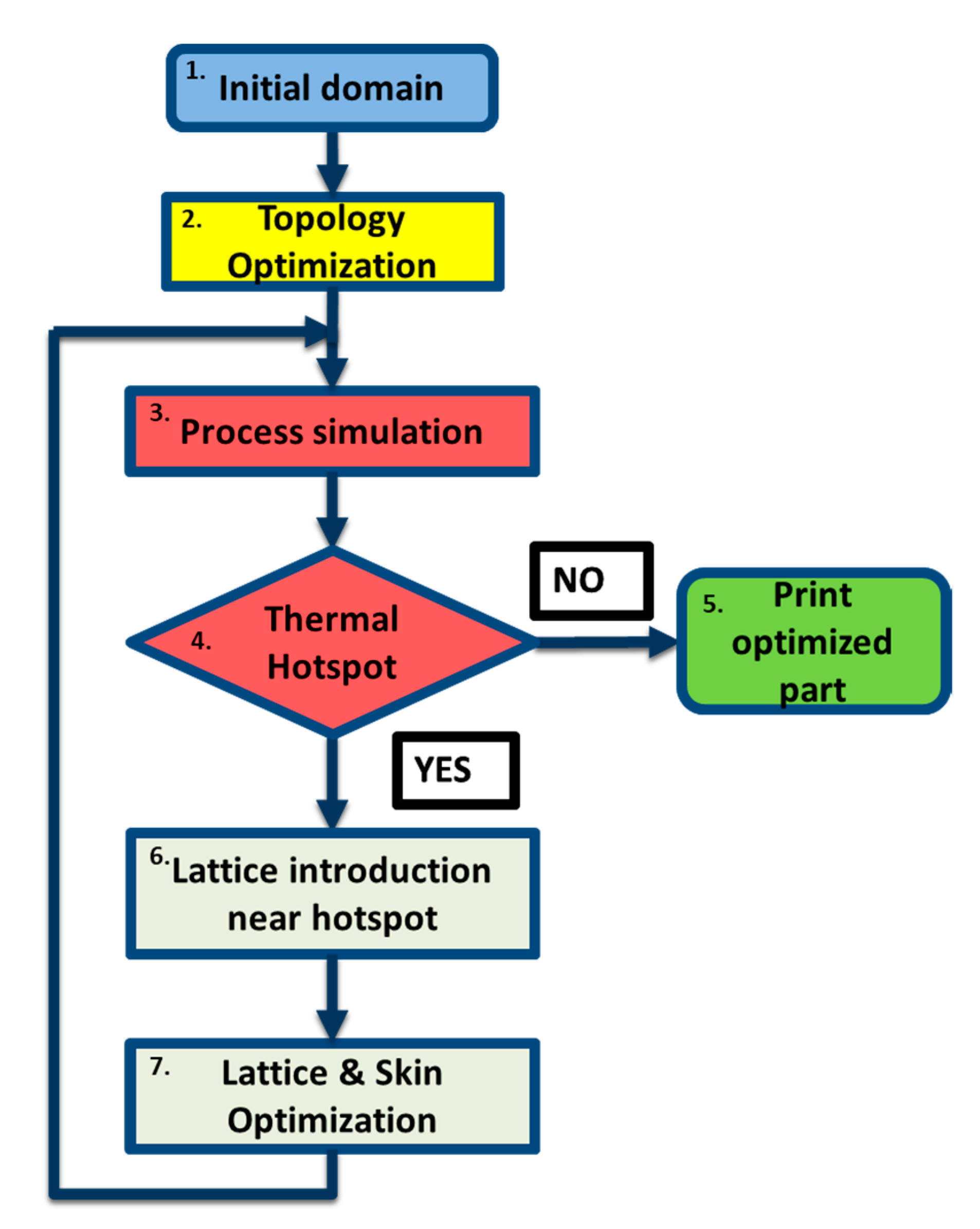
To reduce thermal hotspots in metal AM parts produced using the SLM method, an iterative design approach is proposed which is illustrated in Figure 1. A given initial geometry choice (step 1) is first optimized by a density-based topology optimization process (step 2). To identify any potential issues during the metal printing process, process simulations are run, while considering specific manufacturing parameters and constraints (step 3). The geometry is then analyzed using manufacturing simulations for local thermal accumulations that would occur during printing (step 4). If there are no thermal hotspots, then this design phase is finalized (step 5). In the presence of thermal effects, lattices are introduced in the computationally identified corresponding regions (step 6). These lattices are then further optimized to meet the particular structural objective and constraints of the initial design (step 7). Thereafter, the optimized lattice structure is subjected to further process simulations with the same thermal boundary conditions to check whether the identified thermal accumulations could be successfully alleviated due to the introduction of the lattices (back to step 3). If there are any additional regions of high local thermal accumulation after the introduction of the lattices, the procedure is repeated until no thermal accumulations above a user-specified limit are observed in the process simulations.
Additional details on the simulations involved in this novel design approach are provided next. The topology optimization simulations were run on an in-house supercomputing cluster using 8 cores and 32 GB of RAM. The process simulations and the lattice size optimizations were run locally on an 8-core 3 GHz CPU with 40 GB of RAM and supported by 6GB of GPU.
2.2. Design Optimization and Analysis Steps
To compare the output of the proposed design approach with benchmark solutions available in the literature, a cantilever beam with a point load was chosen as illustrated in Figure 2. The cantilever dimensions of 0.3 × 0.15 × 0.015 m (Figure 2) were determined based on the maximum length that can be accommodated in the build volume of the PBF printer considered in this investigation (details provided next).
The commercially available topology optimization module, Tosca Structure (Dassault Systems, Vélizy-Villacoublay, France), was used for the design optimization step. A titanium alloy, Ti-6Al-4V, was considered as the material for the study because of its widespread adoption in aerospace and biomedical applications stemming from its properties, including resistance to oxidation, acids, alkali and also due to its biocompatibility with the human body [42]. The needed CAD file was generated and preprocessed for finite element analysis (FEA) simulations in the ABAQUS/CAE environment (Dassault Systems). For the cantilever beam, the left end was fixed and a force of 50 kN was applied on the right end. The load was considered such that the stress–strain response of the cantilever was well within the elastic regime of Ti-6Al-4V. Several different mesh densities were analyzed to check the mesh sensitivity of the FEA solution; a final size of 5 mm ten-noded tetrahedral elements was used. This resulted in a total of 18,657 elements with 85,962 degrees of freedom.
A topology optimization problem was then defined to optimize the initial geometry based on the benchmark problem solved in Najafi et al. [43]. In Najafi et al., a vertical point load of F = 1 MN at the middle of the right edge and fixed boundary condition was applied on the left edge. The elastic modulus and Poisson’s ratio considered for this problem were E = 230 × 106 Pa and 0.4, respectively. TFor the current study, a 3D density-based topology optimization formulation, native to the TOSCA module, was used. This gradient-based formulation uses analytic sensitivity approaches similar to most TO methods for computing the derivatives of the objective and constraints. A mesh independent filter is used for filtering the output [44]. For the current study, the objective for the topology optimization problem was to minimize the compliance of the domain. A constraint was applied to limit the volume to 50% of the original. The optimized output was then thresholded to retain only those elements that had a volume fraction of 70% or more. This process was included to reduce any partial density elements and increase the overall solidity of the structure. The thresholding process can lead to jagged surfaces which were smoothed out in this investigation by simplifying the optimized domain. To accomplish this goal, the thresholded domain was exported from Tosca in a compatible mesh format and the optimized domain was recreated using splines in a CAD environment.
2.3. Process Simulation Step
The simplified optimized geometry produced as described in Section 2.1 was saved as a stereolithography (*.stl) file and was imported into the Netfabb Local Simulation utility, which is a commercial FEA solver (Autodesk) capable to simulate the metal AM process using a multiscale approach. Netfabb allows for a range of commercial PBF machines as a user input. This allows for the direct import of the printer build volume to set up the part, determine the print orientation based on the amount of material and print time required, as well as to specify the powder and print parameters such as laser power, laser speed, and hatching size. The metal printer considered for the simulation is EOS M290 that has a build volume of 250 × 250 × 325 mm. A native support structure script was used to generate the support for the part based on the minimum overhang angle preset for EOS M290. Based on the support structure type as well as powder and print process parameters, a microscale sequential thermomechanical simulation was run to generate a high-fidelity simulation of the AM process on a representative volume element (RVE) of 5 mm by 1 mm. A line scanning approach was adopted for the laser with a 67° interlayer rotation angle as this angle has shown to have the most uniform directional stress and minimum deformation [45]. The output of the microscale simulation includes thermal and mechanical histories of the displacement, strain and stress experienced by the RVE. This output is used to set the boundary conditions for the macroscale simulation of the optimized geometry. The formulation of the multiscale model is discussed in Dunbar et al. [46] and Denlinger et al. [47] and the references within it. The solutions provided by the Netfabb code have been experimentally validated in Dunbar et al. [46] and Gouge et al. [33].
A typical Ti-6Al-4V powder for SLM is composed of 89–90% of Ti, 6% of Al and 4% V by weight. The remaining weight is made up of trace amounts of Fe and gases such as C, O, N and H. The solidus temperature of Ti-6Al-4V alloy is approximately 1615 °C [48]. Powder particles not attaining this temperature do not melt and consequently form lack of fusion pores and defects. Hence this temperature is used as the reference for lack of fusion zones. Among all the major metals in Ti-6Al-4V, aluminum has the lowest temperature of evaporation of 2740 °C [49] followed by titanium and vanadium with boiling point at 3280 and 3400 °C, respectively [50,51]. The laser melting process for Ti-6Al-4V attains temperatures of above 3700 °C (>4000 K) with a cooling rate of 40 °C/µs and using process parameters of 170 W pulsed power output and 65 µm of hatch spacing [52]. Sustained localized temperatures above 2740 °C can lead to vaporization loss of aluminum being greater than the vaporization loss of titanium or vanadium, drastically affecting the material composition [50]. Thus, the evaporation temperature of aluminum is used for identifying the local thermal accumulation zones.
2.4. Lattice Introduction Step
To introduce lattices within the design domain, thermal accumulation regions were first identified using the hotspot results from the process simulation described in Section 2.2. Support structures are known to direct thermal energy from the print to the powder bed, which acts as a heat sink. However, as the purpose of this investigation is to demonstrate the effectiveness of lattice structures to reduce local thermal accumulation, it is necessary to deconvolve the effect of support structures from the corresponding effect caused by the lattice. Consequently, lattices were not considered for the computed hotspots. Additionally, since the lattices are architectured porous structures they require additional support themselves, which would increase the complexity of the post-processing when removing the support structures. To avoid the need for additional support structures for the lattices introduced in the design, the lattices were designed such that their struts have an overhang angle more than the minimum angle for the chosen metal printer.
Figure 3 illustrates the lattices considered in this investigation. The lattice strut overhang can be modified by changing the lattice unit cell size. The iso-contour plot of the hotspot was then used to identify the region in which the lattice should be introduced. Since any form of evaporation is to be prevented, the lattices were introduced in the regions where 40% of the hotspot volume exceeds the evaporation temperature of 2740 °C—the temperature of evaporation of aluminum.
2.5. Lattice Optimization Step
The hybrid domain created by introducing lattices into the previously topologically optimized structure that was used for manufacturing process simulations, was further checked for structural stability. Specifically, as the overall stiffness of the optimized structure was reduced due to the introduction of lattices, the resulting hybrid domain was setup for a size optimization of the lattice struts and skin to ensure that the new hybrid domain is capable of withstanding the stresses due to the boundary conditions of the original optimization problem, while also satisfying the objectives and constraints. To this aim, Netfabb provides an in-built size optimization algorithm for lattice structures known as Optimization Utility which was employed for this purpose. The lattice size optimization was setup based on the objective to achieve a target volume with a constraint on the maximum allowable stress in the lattice. Additional stress constraints on the skin can also be considered. Once the lattice was optimized, it was again checked for manufacturability by running additional process simulations. If the hotspots persisted, the above procedure was repeated as needed.
3. Results
3.1. Topology Optimization
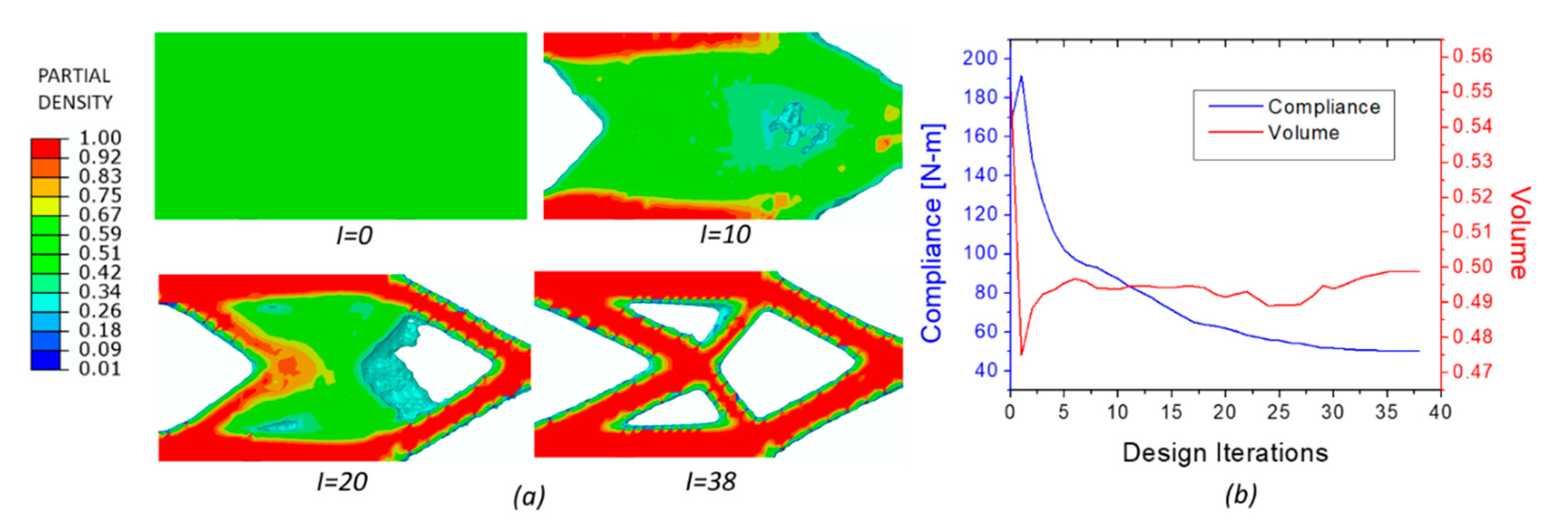
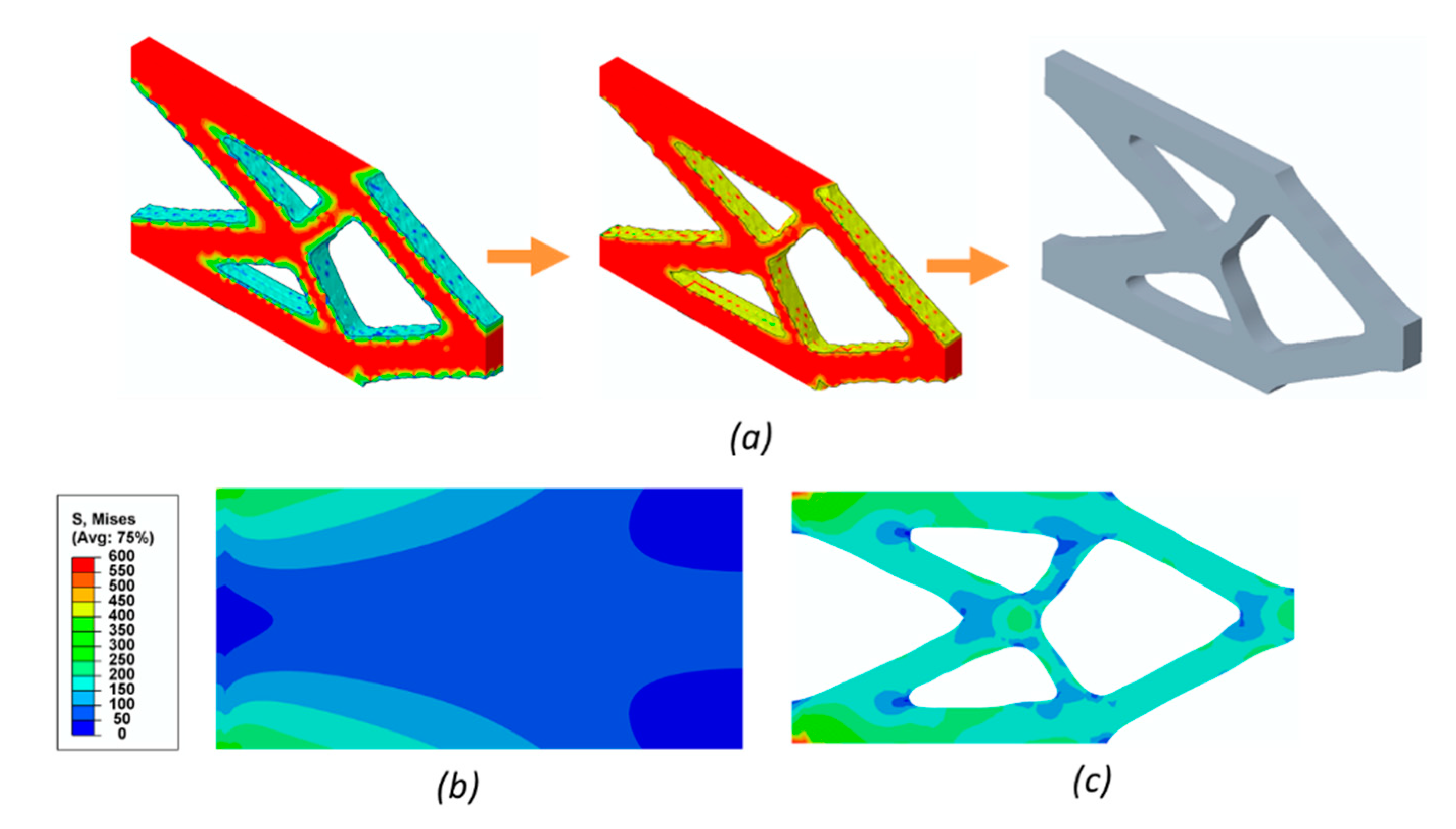
The topology optimization output for the setup described above is shown in Figure 4. The output includes a topology comparable to the results obtained in the benchmark problem by Najafi et al. [43]. The design evolution from iterations 0 to 38 is shown in Figure 4a. The objective and design constraints were met in 38 iterations. In Figure 4b, compliance and volume demonstrate convergence with an increasing number of iterations. To check for local minima, different initial densities of 0, 0.25, 0.75 and 1 were used in the same procedure. The output was found to be topologically similar to the one used in this investigation. A volume fraction of 0.7 or above was assumed in this approach to be solid. The optimized geometry was thresholded to this value to obtain an almost complete solidity of the optimized structure, which is a necessary step to ensure manufacturability. The thresholded optimized output was then converted to a CAD geometry using splines to smooth out any uneven edges through the domain due to the thresholding step. The evolution of the topology optimized geometry to create a CAD for further analysis is shown in Figure 5a. This CAD geometry was analyzed with the same boundary conditions as the cantilever beam for a static load case (Figure 5b–c).
The obtained results in Figure 5c showed high stresses developed at the fixed end. This can be attributed to the stress concentration occurring at the domain edges. The maximum von Mises stress value (592 MPa) was observed in this region as seen in Figure 5c, which is lower than the minimum yield strength (880 MPa) for Ti-6Al-4V. This was compared to the initial design domain of the cantilever that had the maximum von Mises stress of 440 MPa (shown in Figure 5b).
3.2. Process Simulations
For the AM printer considered in this investigation the laser parameters used are listed in Table 1. A Ti-6Al-4V powder consisting of 40 microns sized particles was considered to expedite the print process while ensuring a homogeneous print. The CAD geometry shown in Figure 5a was imported to the process simulation environment, in which a layer-based FEA was run to reduce the computational expense while running thermomechanical simulations. For such process simulations, a voxelated mesh was generated. The voxelated mesh does not capture the edges of the geometry and instead generates a cubical element which encompasses the edge itself. To achieve high accuracy using this discretization, a finer mesh is required which approximately captures the important features of the geometry. A layer-based approach is adopted for the meshing where each element contains 20 layers. Dynamic mesh adaptivity is also employed to reduce the computational expense.
The process simulations yield the temperature history, residual stress, distortion and local thermal accumulation (thermal hotspots) and lack of fusion regions of the part. The regions of local thermal accumulations are identified in the process simulations by using iso-contours of the hotspot volume percentage. These contour are plotted as a percentage of the total volume of the finite element model that is experiencing temperatures over 2740 °C. From the thermal hotspot contour plot, shown in Figure 6, it can be seen that the maximum thermal accumulation occurs near the thin members that formed near the fixed ends of the cantilever. This is expected as thermal accumulation tends to occur near geometries with overhanging sections and sharp contours. Some heat accumulation is also observed near the loading end of the cantilever, again due to the presence of overhanging sections. It can also be observed that the thermal profile is relatively smooth near the regions with structural supports as they tend to channel the heat either from one section of the part to another or from the part to the baseplate.
3.3. Lattice Introduction
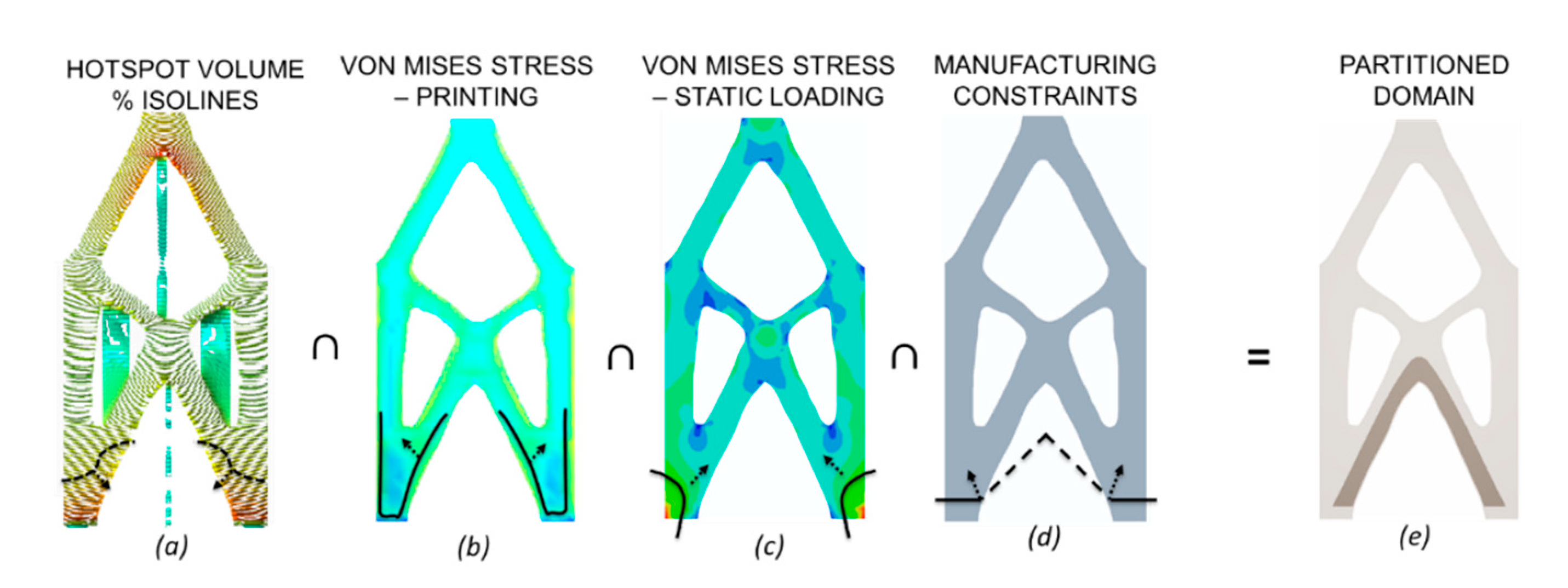
To employ the lattice and attempt to reduce the heat content while addressing the structural requirements of the component requires the lattice domain to be subject to these constraints. As the main requirement of the lattice is to reduce thermal hotspots, the regions with very high thermal accumulation are identified using the iso-contour lines of the hotspot volume, as shown in Figure 7a. The dotted lines signify that the bound can be adjusted spatially to accommodate other constraints without affecting the hotspot region selection. Concurrently, the stresses experienced by the part during the print process are also taken into consideration (Figure 7b). As shown in Figure 7, the von Mises stress during printing is higher near the periphery of the part and decreases as we move away from the edges. To ensure that the part does not become unstable due to the introduction of porosity, the von Mises stress experienced by the optimized domain is used to identify the lower bound of the lattice domain (Figure 7c). Finally, manufacturing constraints are also considered to make sure the lattice domain and the solid part surrounding the lattice domain do not require additional supports t (Figure 7d). This is to ensure a one-to-one comparison between the thermal accumulation in the optimized domain and the domain with the introduced lattices i. A manufacturing constraint is also applied by setting a lower limit to the lattice domain to ensure that the legs are not printed as lattices. This led to the lattices acting as additional support structures thus channeling heat away from the part directly to the base plate.
The volume of the region was 44,141 mm3 and the mass being replaced was 0.19 kg which gave an effective density of the lattice region to be around 0.0041 g/mm3. The angle of the struts is critical for accurate and supportless manufacturing. Lattice-types considered for this purpose are the ‘X’, ‘W’ and ‘star’ (Table 2) as these lattice unit cells within the Netfabb suite can be modified to be manufactured without any supports.
3.4. Lattice Optimization
After the introduction of the lattice, the domain was set up for a lattice optimization investigation. The objective of this optimization process is to minimize the domain volume. The maximum von Mises stress in the lattice struts and skin membranes were constrained to 583 MPa, providing in this way a safety factor of 1.5 for the Ti-6Al-4V component based on a yield strength criterion. An additional constraint of a maximum 1 mm displacement of the whole domain was applied. The optimization run till the objective function converged to a minimum value while satisfying the constraints. The convergence was attained in 49 iterations. As seen in the results illustrated in Figure 8a, the maximum stress occurred within the latticed region at the struts shown in the inset. Therefore, this region was thickened compared with the initial lattice beam diameter of 1 mm to the maximum allowed radius of 4 mm in the central region of the lattice domain. The objective of the optimization was satisfied within the bounds specified for the lattice strut thickness. The same approach was then repeated for the ‘W’ and ‘Star’ lattices. On completion of the optimization, the optimized mesh was exported and smoothed to create a CAD model compatible with the finite element process simulations.
3.5. Effect of Lattice on Hotspot
Figure 9 shows the result of introducing lattices in the hotspot regions. The hotspots in these regions disappear and the hotspots surrounding the lattices regions are reduced as well. Overall, the latticed region displays a more uniform thermal profile. This effect is observed to also affect the bulk regions above the lattices which had a previously higher thermal gradient.
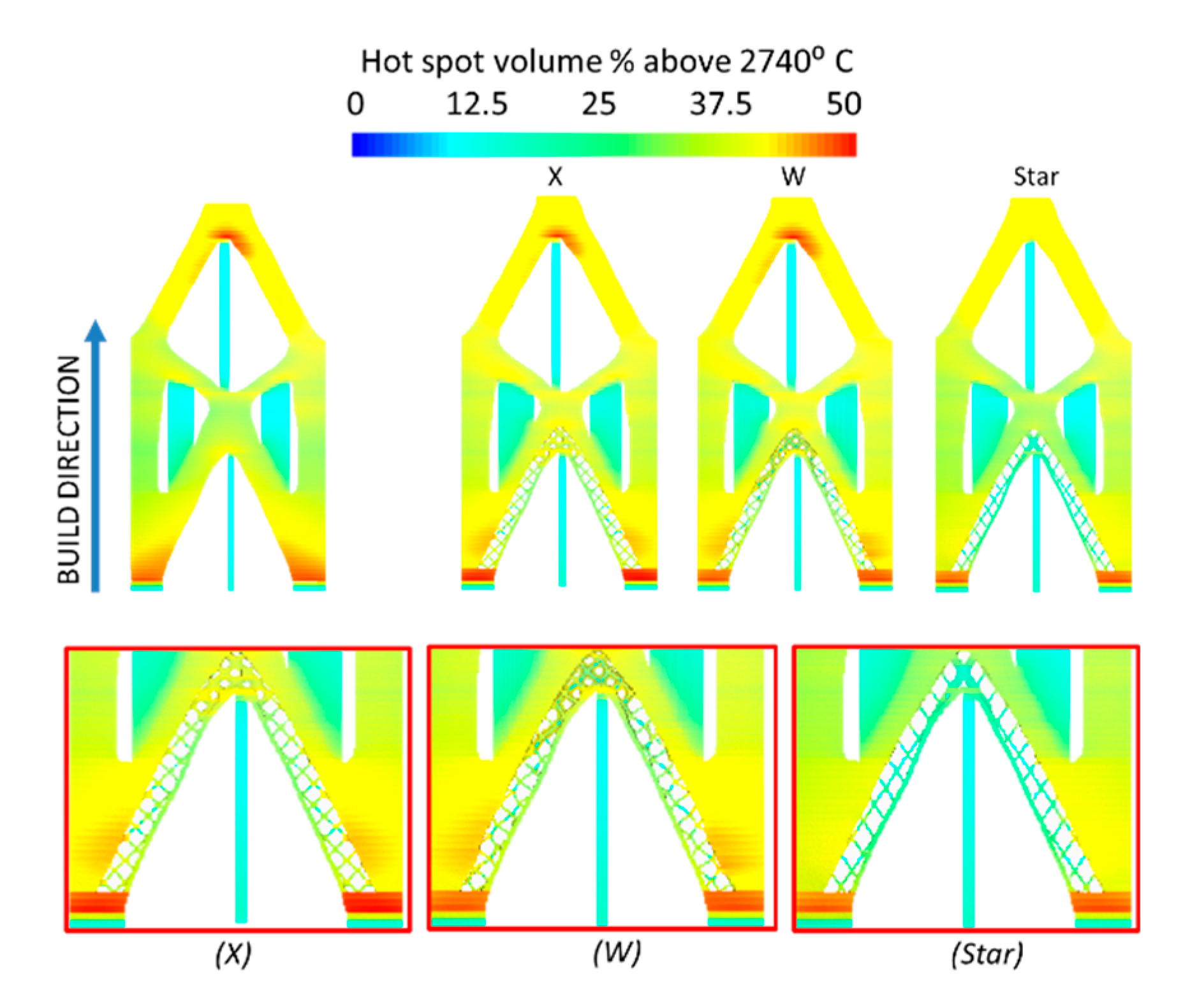
To identify the effect of lattices on the thermal gradient, several different lattices were introduced, and the process simulation was run on these domains. The lattice regions cause, in general, reductions in the temperature gradient within the domain as can be seen in Figure 10. The ‘Star’-type lattice structures exerted the most influence on the thermal profile as they lowered the thermal gradient in the region surrounding the latticed domain. The highest hotspot volume percentage in the latticed domains did not exceed 35% of the element volume with a more uniform thermal distribution throughout the layers. The maximum percentage of hotspot volume remains constant in all three specimens, observed near the lowermost region of the cantilever. As the primary reason for not using additional support structures was to deconvolve the thermal efficiency of lattices from the support structures, smaller support structures near the thin sections can be considered to direct heat away from these sections.
A comparison was additionally made of the different build parameters for the optimized domain and the lattice introduced domains. The lattice domains in general required lower material due to the reduced volume of the domain as well as the reduced print time, as seen in Table 3. The introduction of lattices achieved an additional 10% reduction in the volume and decreasing the print time by 8%. This change in the print time may vary depending on the type of lattice chosen and the dimensions of the lattices. However, even a marginal increase in print time may be offset by the increased reliability in the final print.
4. Discussion
4.1. Topology Optimization and CAD Generation
The topology optimization solution showed a smooth convergence to the minimum for the objective function. The converged solutions for the topology optimization problem were found to be similar to the benchmark problem solutions available in the literature for different initial density values tested for this geometry. The initial volume of the geometry is 6.75 × 105 mm3 according to the given dimensions. The optimization reduces the volume to 49.9% of the original, resulting to a volume of 3.37 × 105 mm3. Thresholding of the optimized geometry further reduces the optimum value of the volume. However, this step is required to reduce the size of the domain and to accurately define a CAD model. For this geometry, it was found that the thresholding value of 0.7 allows for a close approximation of the optimized domain. Another approach to simplify the optimized geometry would have been to use a shape optimization procedure, however, the large number of design variables would lead to a very large computational time in the Tosca environment hence a manual simplification was opted for.
4.2. Lattice Optimization
As elaborated in the introduction, lattice optimization has been considered till now for multifunctional purposes using various techniques. For example, Cheng et al. [53] developed a lattice optimization strategy to optimize the heat conduction of the domain with a constraint on the volume. Here the design is optimized for the performance of the printed part. Our approach, therefore, proposes the use of lattices for improving the heat dissipation during the print process itself and achieve an additional reduction of mass while satisfying the overall structural requirements. The minimum thickness of the lattices was considered to be the smallest that could be manufactured using the SLM process. The gradient-based lattice optimization procedure was expected to find the maximum size of the lattice struts within the bounds mentioned in Table 2. The maximum increase in lattice strut size was observed to be in the central part of the latticed region. This is expected as the central lattice region stabilizes the structure to minimize the overall displacement of the latticed optimized structure. This approach ensured an additional volume reduction on top of the reduction achieved due to topology optimization. The strategy was repeated with different initial sizes of the lattice struts. It was found that the lattice struts consistently increased in size at the central part of the latticed region with reduction observed in lattice sizes in the other parts.
4.3. Process Simulations
Several different parameter selections were simulated to study the effect of these print parameters on the manufacturing outcome. The convergence and accuracy of the process simulations were ensured by following the steps discussed in Dunbar et al. [46] and Denlinger et al. [47]. The local thermal accumulation was also addressed by modifying the print process parameters such as the laser power or the print speed. The lattices reduced the local thermal accumulation in the regions where they were introduced. The ‘Star’ lattice showed the most reduction in thermal accumulations. This can be attributed to the central Z-strut in the star lattice configuration as can be seen in Figure 3. Though reducing the laser power has a direct correlation with the reduction in hotspots, this leads to a lack of melting and fusion of the metal powder. The laser print speed can be also reduced in conjunction with the laser power maintaining the overall energy density [23]. This could allow enough time for the heat to dissipate. However, the build time for the optimized structure is increased drastically and may exceed the build times of the latticed optimized structures without the additional benefit of mass reduction gained using the proposed approach. It is possible to further reduce the effect of hotspots by developing hatching patterns and spacing for a specific area size and shape that optimizes the overall heat accumulation. However, as far as the authors know, such a manufacturing procedure has not been developed so far. Heat treatment methods and HIP are also useful to address the issue of porosity and internal voids, while annealing can be used to reduce the residual stresses. However, these post-processing treatments do not address the issue of material vaporization and consequent crystallization of the molten pool [19] which can affect the overall integrity of the structure. As discussed previously, HIP can lead to crevices that become damage incubation sites.
4.4. Advantages and Limitations of Proposed Methodology
Given the cantilever example, it is clear the methodology can be easily applied on any planar structures. The major advantage of this method is that it addresses the issue of local thermal accumulations and aids in additional weight reduction while maintaining or increasing specific stiffness. The resulting uniform thermal profile of the structure is expected to reduce residual stresses in the part and consequently reduce part distortion after removal from the build plate. The method, however, is limited by the complexity of the lattice structures that can be manufactured. In fact, the manufacturing uncertainties involved in the lattice manufacturing process, discussed in Section 1, may lead to major defects in the printed lattices even for simple lattice designs. However, this problem could be addressed in the near future as the PBF printing technology advances. For now, this effect adds a lower limit on the minimum size of lattice struts that can be used in the proposed approach. There is, however, no upper limit on the size of the parts that can be manufactured uleveraging the digital design approach introduced in this manuscript given a suitable print bed size. Given the two-scale process simulations employed in this approach, the results for large complex parts should be available within hours on a machine similar to the one considered in this study.
5. Conclusions
This work presents a novel digital design methodology using a critical combination of available design optimization and process simulation tools to optimize additively manufactured metal parts for structural performance while at the same time addressing practical manufacturing issues which have been known to lead to disparity in material properties within the print volume. The use of commercially available tools in this investigation was preferred to enable easier adoption of simulation tools for addressing additive manufacturing issues in an industrial setting. Based on the results presented in this manuscript, it could be argued that lattices present a feasible solution in addressing local thermal accumulations in the print volume without compromising the structural integrity of the additively manufactured parts. By addressing the issue of local thermal accumulation, more uniform thermal distributions can be achieved during printing. This has been found to result in reduced porosity and ensures material homogeneity, as discussed in Section 1. Since lattices themselves would require support structures, further research is recommended in developing self-supporting lattices which could further reduce the print time and material use, while preserving the quality of the lattice surface due to the removal of the support structure. Currently preexisting lattice unit cells are used to address the issue of thermal accumulations. However, it is also possible to implement a multiscale structural optimization approach where a lower scale topology optimization algorithm is used to determine the best lattice structure given the thermal and mechanical boundary conditions.
Author Contributions
Conceptualization, A.K. and A.R.N.; methodology, A.K., A.R.N. and V.I.P.; software, V.I.P., A.R.N., A.K.; validation, V.I.P. and A.R.N.; formal analysis, V.I.P.; investigation, V.I.P., A.R.N., A.K.; resources, A.K. and A.R.N.; data curation, V.I.P.; writing—original draft preparation, V.I.P., A.R.N., A.K.; writing—review and editing, V.I.P., A.R.N., A.K.; visualization, V.I.P.; supervision, A.R.N. and, A.K.; project administration, A.K.; funding acquisition, A.K. and A.R.N. All authors have read and agreed to the published version of the manuscript.
Funding
This Project was financed in part by a grant from the Commonwealth of Pennsylvania, Department of Community and Economic Development (Contract No. C000068358 provided by the Manufacturing Pennsylvania Innovation Program to Carnegie Mellon for the project titled: Aerospace Parts Advanced Manufacturing). Any opinions, findings, conclusions or recommendations expressed herein are those of the author(s) and do not reflect the views of the Commonwealth of Pennsylvania or Carnegie Mellon University.
Acknowledgments
The authors acknowledge some of the work reported here was run on Proteus—the high-performance computing cluster supported by Drexel’s University Research Computing Facility. The authors further acknowledge the support provided by Autodesk in performing the process simulations reported in this investigation.
Conflicts of Interest
The authors declare no conflict of interest.
References
- Yan, R.; Luo, D.; Huang, H.; Li, R.; Yu, N.; Liu, C.; Hu, M.; Rong, Q. Electron beam melting in the fabrication of three-dimensional mesh titanium mandibular prosthesis scaffold. Sci. Rep. 2018, 8, 1–10. [Google Scholar] [CrossRef] [Green Version]
- Zadpoor, A.A.; Malda, J. Additive Manufacturing of Biomaterials, Tissues, and Organs. Ann. Biomed. Eng. 2016, 45, 1–11. [Google Scholar] [CrossRef]
- Orme, M.; Madera, I.; Gschweitl, M.; Ferrari, M. Topology Optimization for Additive Manufacturing as an Enabler for Light Weight Flight Hardware. Designs 2018, 2, 51. [Google Scholar] [CrossRef] [Green Version]
- Chadha, C.; Crowe, K.A.; Carmen, C.L.; Patterson, A.E. Exploring an AM-Enabled Combination-of-Functions Approach for Modular Product Design. Designs 2018, 2, 37. [Google Scholar] [CrossRef] [Green Version]
- Singamneni, S.; Lv, Y.; Hewitt, A.; Chalk, R.; Thomas, W.; Jordison, D. Additive Manufacturing for the Aircraft Industry: A Review. J. Aeronaut. Aerosp. Eng. 2019, 8, 1–13. [Google Scholar] [CrossRef] [Green Version]
- Wieding, J.; Jonitz, A.; Bader, R. The Effect of Structural Design on Mechanical Properties and Cellular Response of Additive Manufactured Titanium Scaffolds. Materials 2012, 5, 1336–1347. [Google Scholar] [CrossRef]
- Bose, S.; Robertson, S.F.; Bandyopadhyay, A. Surface modification of biomaterials and biomedical devices using additive manufacturing. Acta Biomater. 2018, 66, 6–22. [Google Scholar] [CrossRef]
- Gibson, L.J.; Ashby, M.F. Cellular Solids: Structure and Properties; Cambridge University Press: Cambridge, UK, 1997. [Google Scholar]
- Carroll, B.E.; Palmer, T.A.; Beese, A.M. Anisotropic tensile behavior of Ti-6Al-4V components fabricated with directed energy deposition additive manufacturing. Acta Mater. 2015, 87, 309–320. [Google Scholar] [CrossRef]
- Evans, A.; Hutchinson, J.; Ashby, M. Multifunctionality of cellular metal systems. Prog. Mater. Sci. 1998, 43, 171–221. [Google Scholar] [CrossRef]
- Wauthle, R.; Vrancken, B.; Beynaerts, B.; Jorissen, K.; Schrooten, J.; Kruth, J.-P.; Van Humbeeck, J. Effects of build orientation and heat treatment on the microstructure and mechanical properties of selective laser melted Ti6Al4V lattice structures. Addit. Manuf. 2015, 5, 77–84. [Google Scholar] [CrossRef]
- DebRoy, T.; Wei, H.L.; Zuback, J.S.; Mukherjee, T.; Elmer, J.W.; Milewski, J.O.; Beese, A.M.; Wilson-Heid, A.; De, A.; Zhang, W. Additive manufacturing of metallic components–Process, structure and properties. Prog. Mater. Sci. 2018, 92, 112–224. [Google Scholar] [CrossRef]
- Murr, L.; Gaytan, S.M.; Ramirez, D.A.; Martinez, E.; Hernandez, J.; Amato, K.N.; Shindo, P.W.; Medina, F.R.; Wicker, R.B. Metal Fabrication by Additive Manufacturing Using Laser and Electron Beam Melting Technologies. J. Mater. Sci. Technol. 2012, 28, 1–14. [Google Scholar] [CrossRef]
- Calignano, F. Investigation of the accuracy and roughness in the laser powder bed fusion process. Virtual Phys. Prototyp. 2018, 13, 97–104. [Google Scholar] [CrossRef]
- Saboori, A.; Aversa, A.; Marchese, G.; Biamino, S.; Lombardi, M.; Fino, P. Microstructure and Mechanical Properties of AISI 316L Produced by Directed Energy Deposition-Based Additive Manufacturing: A Review. Appl. Sci. 2020, 10, 3310. [Google Scholar] [CrossRef]
- Beese, A.M.; Carroll, B.E. Review of Mechanical Properties of Ti-6Al-4V Made by Laser-Based Additive Manufacturing Using Powder Feedstock. JOM 2015, 68, 724–734. [Google Scholar] [CrossRef]
- Gaynor, A.T.; Guest, J.K. Topology optimization considering overhang constraints: Eliminating sacrificial support material in additive manufacturing through design. Struct. Multidiscip. Optim. 2016, 54, 1157–1172. [Google Scholar] [CrossRef]
- Langelaar, M. An additive manufacturing filter for topology optimization of print-ready designs. Struct. Multidiscip. Optim. 2016, 55, 871–883. [Google Scholar] [CrossRef] [Green Version]
- Wang, C.; Qian, X. Simultaneous optimization of build orientation and topology for additive manufacturing. Addit. Manuf. 2020, 34. [Google Scholar] [CrossRef]
- Han, Y.; Xu, B.; Zhao, L.; Xie, Y.M. Topology optimization of continuum structures under hybrid additive-subtractive manufacturing constraints. Struct. Multidiscip. Optim. 2019, 60, 2571–2595. [Google Scholar] [CrossRef]
- Manogharan, G.; Wysk, R.; Harrysson, O.; Aman, R. AIMS-A Metal Additive-hybrid Manufacturing System: System Architecture and Attributes. Procedia Manuf. 2015, 1, 273–286. [Google Scholar] [CrossRef] [Green Version]
- Panesar, A.; Abdi, M.; Hickman, D.; Ashcroft, I. Strategies for functionally graded lattice structures derived using topology optimisation for Additive Manufacturing. Addit. Manuf. 2018, 19, 81–94. [Google Scholar] [CrossRef]
- Echeta, I.; Feng, X.; Dutton, B.; Leach, R.; Piano, S. Review of defects in lattice structures manufactured by powder bed fusion. Int. J. Adv. Manuf. Technol. 2019, 106, 2649–2668. [Google Scholar] [CrossRef] [Green Version]
- Pasini, D.; Guest, J.K. Imperfect architected materials: Mechanics and topology optimization. MRS Bull. 2019, 44, 766–772. [Google Scholar] [CrossRef]
- Miki, T.; Yamada, T. Topology optimization for considering distortion in additive manufacturing. Struct. Multidiscip. Optim. 2020. [Google Scholar] [CrossRef]
- Liu, J.; Gaynor, A.T.; Chen, S.; Kang, Z.; Suresh, K.; Takezawa, A.; Li, L.; Kato, J.; Tang, J.; Wang, C.C.L.; et al. Current and future trends in topology optimization for additive manufacturing. Struct. Multidiscip. Optim. 2018, 57, 2457–2483. [Google Scholar] [CrossRef] [Green Version]
- Li, C.; Liu, Z.; Fang, X.; Guo, Y.B. Residual Stress in Metal Additive Manufacturing. Procedia CIRP 2018, 71, 348–353. [Google Scholar] [CrossRef]
- Simson, T.; Emmel, A.; Dwars, A.; Böhm, J. Residual stress measurements on AISI 316L samples manufactured by selective laser melting. Addit. Manuf. 2017, 17, 183–189. [Google Scholar] [CrossRef]
- Baufeld, B.; Biest, O.; Gault, R. Additive manufacturing of Ti-6Al-4V components by shaped metal deposition: Microstructure and mechanical properties. Mater. Des. 2010, 31, S106–S111. [Google Scholar] [CrossRef]
- Shao, J.; Yu, G.; He, X.; Li, S.; Chen, R.; Zhao, Y. Grain size evolution under different cooling rate in laser additive manufacturing of superalloy. Opt. Laser Technol. 2019, 119. [Google Scholar] [CrossRef] [Green Version]
- Gockel, J.; Beuth, J.; Taminger, K. Integrated control of solidification microstructure and melt pool dimensions in electron beam wire feed additive manufacturing of Ti-6Al-4V. Addit. Manuf. 2014, 1, 119–126. [Google Scholar] [CrossRef]
- Monkova, K.; Monka, P. Qualitative parameters of complex part produced by additive approach. In Proceedings of the 2017 8th International Conference on Mechanical and Aerospace Engineering (ICMAE), Prague, Czech Republic, 22–25 July 2017; Institute of Electrical and Electronics Engineers (IEEE): Prague, Czech Republic, 2017; pp. 691–694. [Google Scholar]
- Gouge, M.; Denlinger, E.; Irwin, J.; Li, C.; Michaleris, P. Experimental validation of thermo-mechanical part-scale modeling for laser powder bed fusion processes. Addit. Manuf. 2019, 29, 100771. [Google Scholar] [CrossRef]
- Cheng, L.; To, A.C. Part-scale build orientation optimization for minimizing residual stress and support volume for metal additive manufacturing: Theory and experimental validation. Comput. Des. 2019, 113, 1–23. [Google Scholar] [CrossRef]
- Choo, H.; Sham, K.-L.; Bohling, J.; Ngo, A.; Xiao, X.; Ren, Y.; Depond, P.; Matthews, M.J.; Garlea, E. Effect of laser power on defect, texture, and microstructure of a laser powder bed fusion processed 316L stainless steel. Mater. Des. 2019, 164, 107534. [Google Scholar] [CrossRef]
- Zhang, B.; Meng, W.J.; Shamsaei, N.; Phan, N.; Shamsaei, N. Effect of heat treatments on pore morphology and microstructure of laser additive manufactured parts. Mater. Des. Process. Commun. 2019, 1, e29. [Google Scholar] [CrossRef] [Green Version]
- Bobbio, L.D.; Qin, S.; Dunbar, A.; Michaleris, P.; Beese, A.M. Characterization of the strength of support structures used in powder bed fusion additive manufacturing of Ti-6Al-4V. Addit. Manuf. 2017, 14, 60–68. [Google Scholar] [CrossRef]
- Ranjan, R.; Yang, Y.; Ayas, C.; Langelaar, M.; Van Keulen, F. Controlling local overheating in topology optimization for additive manufacturing. In Proceedings of the Euspen Special Interest Group Meeting: Additive Manufacturing, Leuven, Belgium, 10–11 October 2017. [Google Scholar]
- Son, K.N.; Weibel, J.A.; Kumaresan, V.; Garimella, S.V. Design of multifunctional lattice-frame materials for compact heat exchangers. Int. J. Heat Mass Transf. 2017, 115, 619–629. [Google Scholar] [CrossRef] [Green Version]
- Cheng, L.; Liu, J.; Liang, X.; To, A.C. Coupling lattice structure topology optimization with design-dependent feature evolution for additive manufactured heat conduction design. Comput. Methods Appl. Mech. Eng. 2018, 332, 408–439. [Google Scholar] [CrossRef]
- Lynch, M.E.; Mordasky, M.; Cheng, L.; To, A. Design, testing, and mechanical behavior of additively manufactured casing with optimized lattice structure. Addit. Manuf. 2018, 22, 462–471. [Google Scholar] [CrossRef]
- Sidambe, A.T. Biocompatibility of Advanced Manufactured Titanium Implants-A Review. Materials 2014, 7, 8168–8188. [Google Scholar] [CrossRef] [Green Version]
- Najafi, A.R.; Safdari, M.; Tortorelli, D.A.; Geubelle, P. Shape optimization using a NURBS-based interface-enriched generalized FEM. Int. J. Numer. Methods Eng. 2017, 111, 927–954. [Google Scholar] [CrossRef]
- Zuo, Z.H.; Xie, Y. A simple and compact Python code for complex 3D topology optimization. Adv. Eng. Softw. 2015, 85, 1–11. [Google Scholar] [CrossRef]
- Cheng, B.; Shrestha, S.; Chou, Y.K. Stress and Deformation Evaluations of Scanning Strategy Effect in Selective Laser Melting. Processing 2016, 12. [Google Scholar] [CrossRef]
- Dunbar, A.J.; Denlinger, E.R.; Gouge, M.F.; Michaleris, P. Experimental validation of finite element modeling for laser powder bed fusion deformation. Addit. Manuf. 2016, 12, 108–120. [Google Scholar] [CrossRef]
- Denlinger, E.R.; Gouge, M.; Irwin, J.; Michaleris, P. Thermomechanical model development and in situ experimental validation of the Laser Powder-Bed Fusion process. Addit. Manuf. 2017, 16, 73–80. [Google Scholar] [CrossRef]
- Brown, W.F.; Mindlin, H.; Ho, C.Y. Aerospace Structural Metals Handbook; CINDAS/Purdue University: West Lafayette, IN, USA, 1995. [Google Scholar]
- Xiao, H. 11.5.2.1 Thermal Evaporation. In Introduction to Semiconductor Manufacturing Technology; Society of Photo-Optical Instrumentation Engineers (SPIE): Bellingham, WA, USA, 2012; p. 485. [Google Scholar]
- Zhang, G.; Chen, J.; Zheng, M.; Yan, Z.; Lu, X.; Lin, X.; Huang, W. Element Vaporization of Ti-6Al-4V Alloy during Selective Laser Melting. Metals 2020, 10, 435. [Google Scholar] [CrossRef] [Green Version]
- Rai, R.; Elmer, J.W.; Palmer, T.A.; Debroy, T. Heat transfer and fluid flow during keyhole mode laser welding of tantalum, Ti-6Al-4V, 304L stainless steel and vanadium. J. Phys. D Appl. Phys. 2007, 40, 5753–5766. [Google Scholar] [CrossRef] [Green Version]
- Hooper, P. Melt pool temperature and cooling rates in laser powder bed fusion. Addit. Manuf. 2018, 22, 548–559. [Google Scholar] [CrossRef]
- Cheng, L.; Liu, J.; To, A.C. Concurrent lattice infill with feature evolution optimization for additive manufactured heat conduction design. Struct. Multidiscip. Optim. 2018, 58, 511–535. [Google Scholar] [CrossRef]
Figure 1.
Proposed digital design approach for metal additive manufacturing to address thermal effects.
Figure 1.
Proposed digital design approach for metal additive manufacturing to address thermal effects.

Figure 2.
Selected domain for the design approach in this investigation.
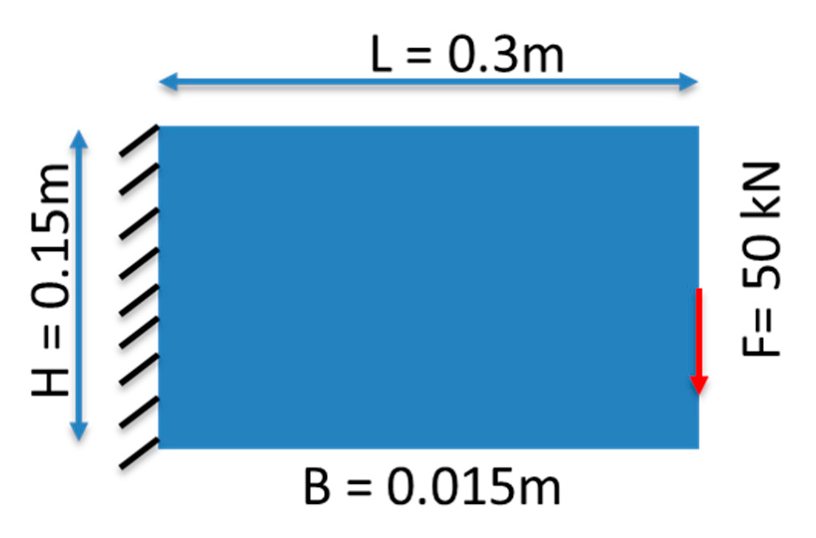
Figure 3.
The isometric and planar views of the ‘X’ lattice (left), ‘W’ lattice (center) and the ‘Star’ lattice (right). The overhang angles for the members are ensured to be more than 45 degrees from the horizontal to ensure supportless printing.
Figure 3.
The isometric and planar views of the ‘X’ lattice (left), ‘W’ lattice (center) and the ‘Star’ lattice (right). The overhang angles for the members are ensured to be more than 45 degrees from the horizontal to ensure supportless printing.
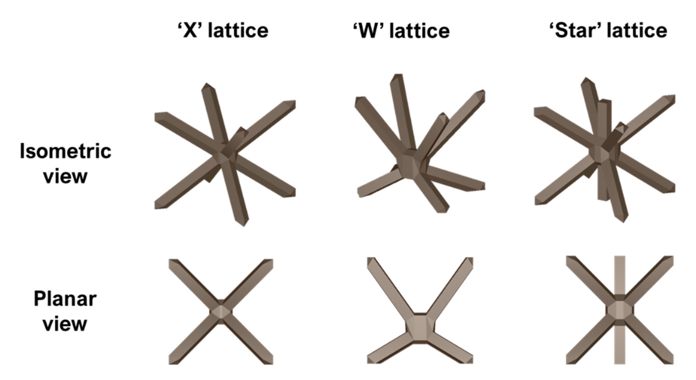
Figure 4.
(a) Evolution of the design domain using topology optimization and (b) the history plot of the compliance and volume for the optimization process.
Figure 4.
(a) Evolution of the design domain using topology optimization and (b) the history plot of the compliance and volume for the optimization process.

Figure 5.
(a) Domain simplification methodology by using the output from topology optimization, thresholding the mesh to a user-specified partial density, designing a simplified CAD geometry using splines for introduction of lattices. (bottom) Static analysis plot shown the von Mises stress for (b) the original design domain and (c) the topology optimized output.

Figure 6.
Hot spot contour plot from a process simulation of the optimized geometry. The inset shows the region with the highest thermal accumulations in terms of the percentage of finite element volume.
Figure 6.
Hot spot contour plot from a process simulation of the optimized geometry. The inset shows the region with the highest thermal accumulations in terms of the percentage of finite element volume.
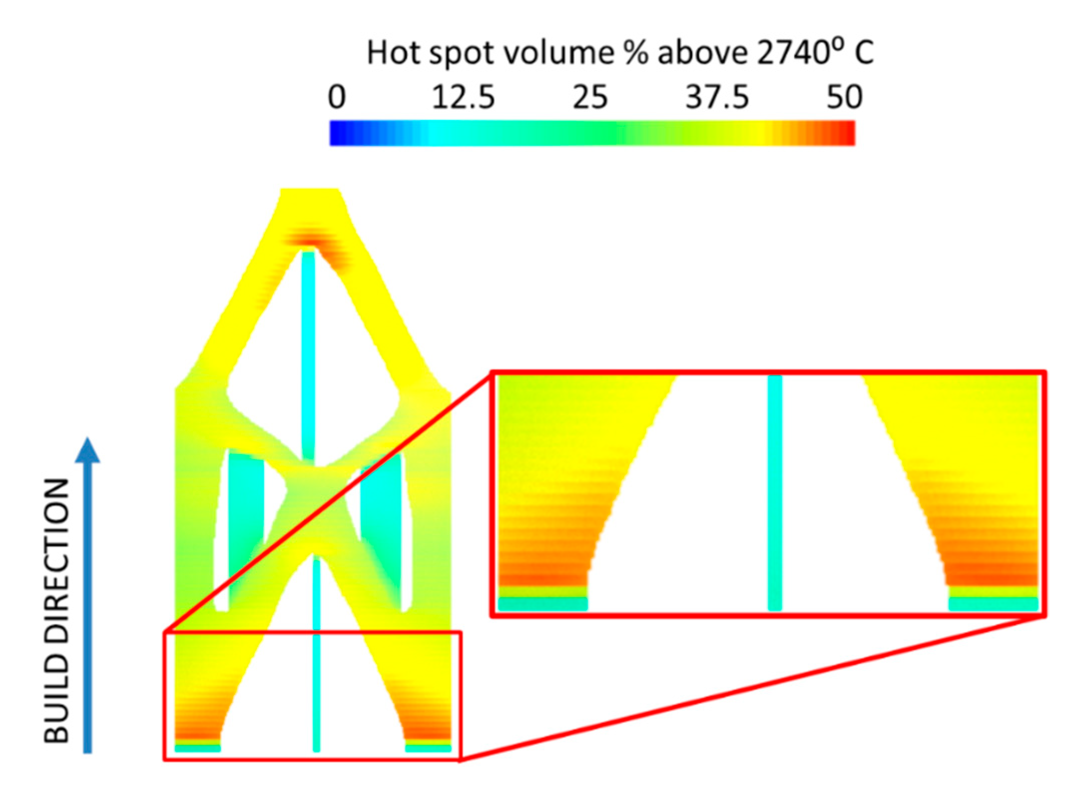
Figure 7.
Identification of region for lattice introduction by using: (a) the isolines of the hotspot volume in printing, (b) the von Mises stress buildup in the part during printing, (c) the von Mises stress experienced by the optimized cantilever part during static loading and (d) the manufacturing constraints of minimum overhang angle and clearance from the base to create (e) the partitioned domain. The dotted arrows indicate the region to be considered for lattice introduction. Continuous black lines are fixed. Dotted black lines can be adjusted to accommodate the changing parameters for a given setup (e.g., varying hotspot buildup (a) for the same part using different process parameters or different allowable overhang angles for different selective laser melting (SLM) machines (d)).

Figure 8.
Lattice optimization iterations and the evolution of the lattice thickness in iterations 1, 10 and 49 shown in (a), (b) and (c) respectively; (d) the convergence history of the optimization.
Figure 8.
Lattice optimization iterations and the evolution of the lattice thickness in iterations 1, 10 and 49 shown in (a), (b) and (c) respectively; (d) the convergence history of the optimization.
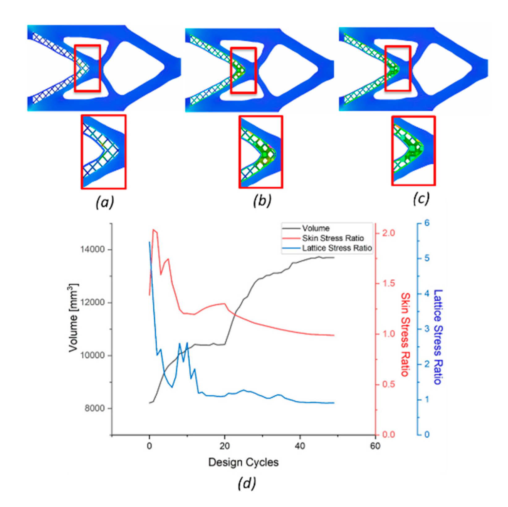
Figure 9.
Comparing the hotspot observed in (a) the optimized domain and (b) the ‘X’ lattice introduced optimized domain. The inset in (a) shows the regions affected by the hotspot and in (b) the effect of lattice introduction
Figure 9.
Comparing the hotspot observed in (a) the optimized domain and (b) the ‘X’ lattice introduced optimized domain. The inset in (a) shows the regions affected by the hotspot and in (b) the effect of lattice introduction
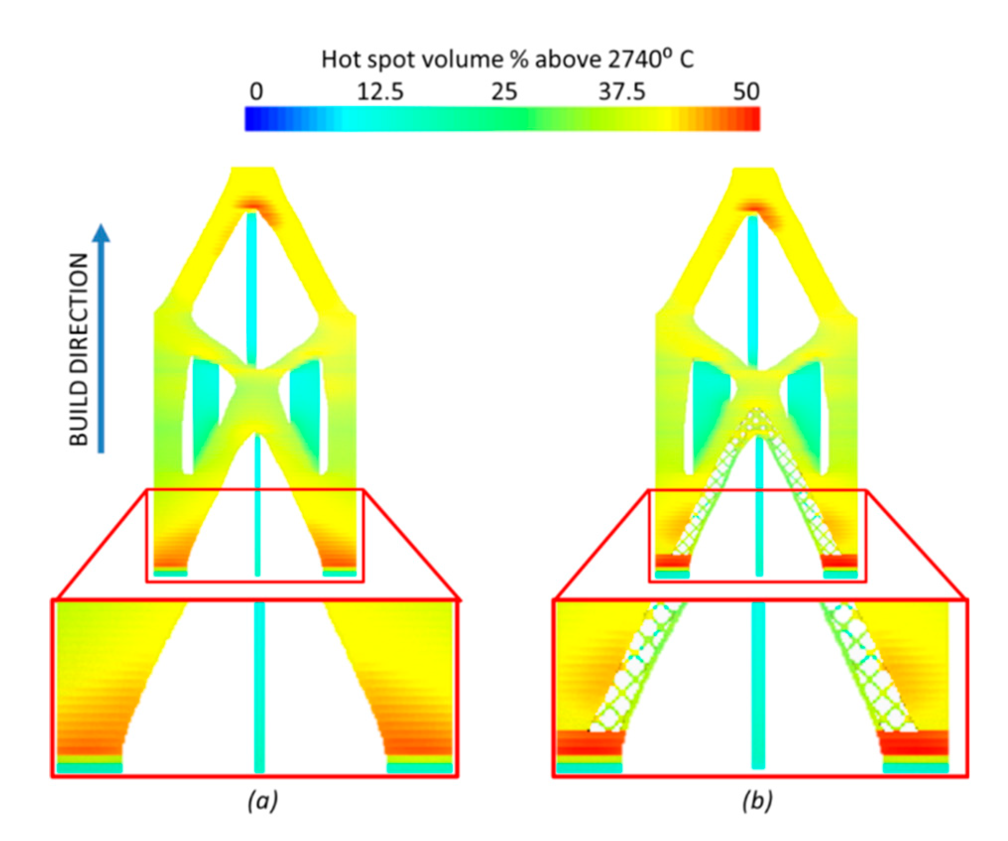
Figure 10.
Comparing the hotspot observed in the optimized domain and the lattice introduced optimized domains using the ‘X’, ‘W’ and ‘Star’ lattices. The insets in (X), (W) and (Star) shows the effect of the different lattices on the hotspots.
Figure 10.
Comparing the hotspot observed in the optimized domain and the lattice introduced optimized domains using the ‘X’, ‘W’ and ‘Star’ lattices. The insets in (X), (W) and (Star) shows the effect of the different lattices on the hotspots.

Table 1.
Process simulation parameters.
| Parameters | Value |
|---|---|
| SLM Printer model | EOS M 290 |
| Laser Power (Watts) | 250 |
| Heat source absorption efficiency (%) | 40 |
| Laser beam diameter (mm) | 0.15 |
| Travel speed (mm/s) | 1000 |
| Layer thickness (mm) | 0.04 |
| Hatch spacing (mm) | 0.15 |
| Interlayer rotation angle | 67° |
Table 2.
Lattice optimization parameters with respect to the unit cell used.
| Lattice Parameters | Value |
|---|---|
| Unit cell | X/W/Star |
| Unit cell dimension (mm) | 15 × 10 × 10 |
| Min. beam radius (mm) | 1 |
| Max. beam radius (mm) | 4 |
Table 3.
Build parameters comparison for different lattice structures.
| Parameters | Topology Optimized Beam | TO Beam with X Lattice | TO Beam with W Lattice | TO Beam with Star Lattice |
|---|---|---|---|---|
| Part Volume (cm3) | 307.75 | 267.73 | 272.21 | 269.85 |
| Support Volume (cm3) | 8.16 | 8.95 | 8.94 | 8.96 |
| Build time (hhh:mm:ss) | 84:21:59 | 76:30:55 | 77:24:51 | 77:47:56 |
© 2020 by the authors. Licensee MDPI, Basel, Switzerland. This article is an open access article distributed under the terms and conditions of the Creative Commons Attribution (CC BY) license (http://creativecommons.org/licenses/by/4.0/).
Share and Cite
MDPI and ACS Style
I. Perumal, V.; R. Najafi, A.; Kontsos, A. A Novel Digital Design Approach for Metal Additive Manufacturing to Address Local Thermal Effects. Designs 2020, 4, 41. https://0-doi-org.brum.beds.ac.uk/10.3390/designs4040041
AMA Style
I. Perumal V, R. Najafi A, Kontsos A. A Novel Digital Design Approach for Metal Additive Manufacturing to Address Local Thermal Effects. Designs. 2020; 4(4):41. https://0-doi-org.brum.beds.ac.uk/10.3390/designs4040041
Chicago/Turabian StyleI. Perumal, Vignesh, Ahmad R. Najafi, and Antonios Kontsos. 2020. "A Novel Digital Design Approach for Metal Additive Manufacturing to Address Local Thermal Effects" Designs 4, no. 4: 41. https://0-doi-org.brum.beds.ac.uk/10.3390/designs4040041