
Capacitor Commutation Method for MVDC Hybrid Circuit Breakers


School of EE & Control Engineering, Kongju National University, 275 Budae Dong, Seobuk Gu, Cheonan Si 31080, Korea
Designs 2021, 5(2), 28; https://0-doi-org.brum.beds.ac.uk/10.3390/designs5020028
Submission received: 16 March 2021
/
Revised: 6 April 2021
/
Accepted: 8 April 2021
/
Published: 13 April 2021
(This article belongs to the Section Electrical Engineering Design)
Abstract
:The medium voltage DC (MVDC) type system can connect multiple terminals to a common MVDC bus, so it is possible to connect several renewable DC power sources to the common MVDC bus, but a DC circuit breaker is needed to isolate short circuit accidents that may occur in the MVDC bus. For this purpose, the concept of a hybrid DC circuit breaker that takes advantage of a low conduction loss contact type switch and an arcless-breaking semiconductor switch has been proposed. During break the hybrid switch, a dedicated current commutation device is required to temporarily bypass the load current flowing through the main switch into a semiconductor switch branch. Existing current commutation methods include a proactive method and a reverse current injection method by a LC (Inductor-capacitor) resonant circuit. This paper proposes a power circuit of a new MVDC hybrid circuit breaker using a low withstanding voltage capacitor branch for commutation and a sequence controller according to it, and verifies its operation through an experiment.
1. Introduction
With the recent advent of large-scale renewable power plants, research on voltage-type medium voltage DC (MVDC) systems to secure system stability has become an important issue. The voltage type MVDC system is capable of connecting multiple terminals to a common MVDC bus, allowing more stable operation than the AC system for intermittent renewable power generation and supplying power generated from the offshore to the inland with less transmission loss [1,2]. However, in order to isolate short circuit accidents that may occur in the MVDC bus, a DC circuit breaker is needed [3].
Unlike AC, DC does not generate points where the current becomes zero by itself and flows constantly. Therefore, there is a risk of electric fire due to sustained breaking arc during the load current is cut off with an existing electric contact type circuit breaker. In particular, in the case of an MVDC circuit breaker that must cut off a direct current of thousands to tens of thousands of amps in a high-voltage system to which a voltage of tens to hundreds of thousands of volts is applied, a stable circuit breaker operation without severe breaking arc is essential. Conventional electrical contact type switches have very-small conduction losses, but arcs are generated when circuit is cut off, leading to device failure and fire [4,5]. Switches using semiconductors have the advantage of not accompanying arcs when circuit is cut off, but there is a problem that conduction losses are large [6,7].
Recently, the concept of a hybrid DC circuit breaker that takes advantage of the electrical contact type main switch and semiconductor switch has been proposed [8]. The hybrid DC circuit breaker is a structure in which a semiconductor switch string is connected in parallel with a mechanical contact type switch. Such a hybrid DC circuit breaker supplies a load current with low conduction losses through an electrical contact type switch when the circuit is turned on, and temporarily commutates the load current flowing in the main switch to a semiconductor switch string during the circuit is cut off, then finally turn off the semiconductor switch string without arc. Here, one of the important technical issues is stable and low-cost commutation device.
In low voltage DC (LVDC) systems where the supply voltage level is not more than 1500 V, the semiconductor switch string is normally consisted with at least two series connected semiconductor switches. Thus, the turn-on-voltage drop of the semiconductor switch string in LVDC circuit breaker is usually less than 10 V (may be around 5~6 V). Besides, breaking arcs occur in the electrical contact type main switch when the voltage difference between the two electrodes becomes more than 10 V. In order to generate an arc discharge, the arc initiating voltage of about 10 V is rapidly formed between the electrical contacts because a voltage to cause plasma generation by collision of electrons and air molecules is required [9]. Thus, when a power semiconductor switch with a turn-on-voltage drop of under the arc initiating voltage is connected in parallel to both ends of the electrical contacts, the current flowing through the electrical contact is immediately bypassed to the semiconductor switch due to the arc initiating voltage (around 10 V) generated when the electrical contact is opened [10]. Here in after, this kind of commutation is called as natural commutation.
Natural commutation is the most simple method, because the commutation measure is the arc initiation voltage that occurs between the contacts of mechanical switch itself. When the turn-on-voltage drop of the semiconductor switch string is lower than the arc initiating voltage of the main switch, the load current easily commutates to the semiconductor switch string without the arc when the circuit is cut off. However, the arc initiation voltage varies very widely according to environmental conditions. If the arc initiation voltage becomes lower than the turn-on-voltage drop of the semiconductor switch string, the breaking arc sustains in the hybrid circuit breakers which can deteriorate facility and danger for human.
In order to construct a semiconductor switch string in the MVDC transmission system with a high-voltage level, a large number of semiconductor switches must be connected in series and used, thereby turning on the semiconductor switch string, the size of the voltage required across the semiconductor switch string (VCEON) is also considerably increased. For example, if the voltage level of the MVDC transmission system is 100 kV, the semiconductor switch string should normally consisted with at least 100 with 1200 volt class IGBTs in series. In this case, the size of the on drop voltage across the semiconductor switch string (VCEON) required for this is about 200 volts or more. Thus, severe breaking arc occurs during commutation of the load current from main switch branch to semiconductor switch branch with conventional natural commutation method in MVDC level [11].
Therefore, a dedicated current commutation device is required to temporarily bypass the load current flowing in the contact type main switch branch to a semiconductor switch branch without breaking arc during the circuit is cut off. Existing current commutation methods can be classified as two types; one is a proactive method and the other is a reverse current injection method by a LC (Inductor-capacitor) resonant circuit.
Proactive method is composed by inserting a dedicated commutation semiconductor switch, from now we call it as line commutation switch (LCS), in series with the contact type main switch [12,13]. When the circuit is turned on, the LCS connected in series with the main switch is also completely turned on, causing only a small voltage drop. During the circuit is cut off, the LCS connected in series with the main switch is operated in the active operation mode to increase the applied voltage across the semiconductor switch string, that is connected parallel to the main switch branch circuit, so that the load current flowing in the main switch is commutated to the semiconductor switch string branch without breaking arc. In this method, the conduction loss is increased due to the voltage drop occurring at the dedicated commutation semiconductor switch while the circuit is turned on, and additional heat dissipation cost for the dedicated commutation semiconductor switch is required.
The reverse current injection method by LC resonance is configured by connecting the LC resonance branch circuit in parallel with the main switch branch circuit [12,13,14,15,16,17]. When the circuit is closed, the load current flows only through the mechanical contacts of the main switch, so the conduction efficiency is very high. When the circuit is cut off, LC resonance current is generated to create a current zero point in the main switch, thereby breaking the main switch without severe breaking arc, and commutating the load current into a semiconductor switch string branch. This method generates high voltage/current stress equal to twice the source voltage and load current in the LC resonant circuit, so the cost of the LC resonant circuit is high and design of enough contact capacity of the main switch is required. Furthermore, short breaking arc occurs during resonance that also a weak point of this type of commutation method [17].
In this study, a power circuit of a new MVDC hybrid circuit breaker using a low withstanding voltage capacitor branch for commutation and a sequence controller according to it is proposed. The voltage stress on the commutation capacitor is not more than the voltage drop across the semiconductor switch string (VCEON) that is very low compared with the supply voltage level. The commutation circuit is very simple, only the commutation capacitor branch that is connected parallel to the semiconductor switch string, and there is no control element to handle the commutating operation which gives high reliability for the proposed hybrid circuit breaker. Table 1 shows the pros and cons of the proposed commutation method compared with existing commutation methods.
2. Proposed Hybrid MVDC Circuit Breaker
2.1. Power Circuit Structure
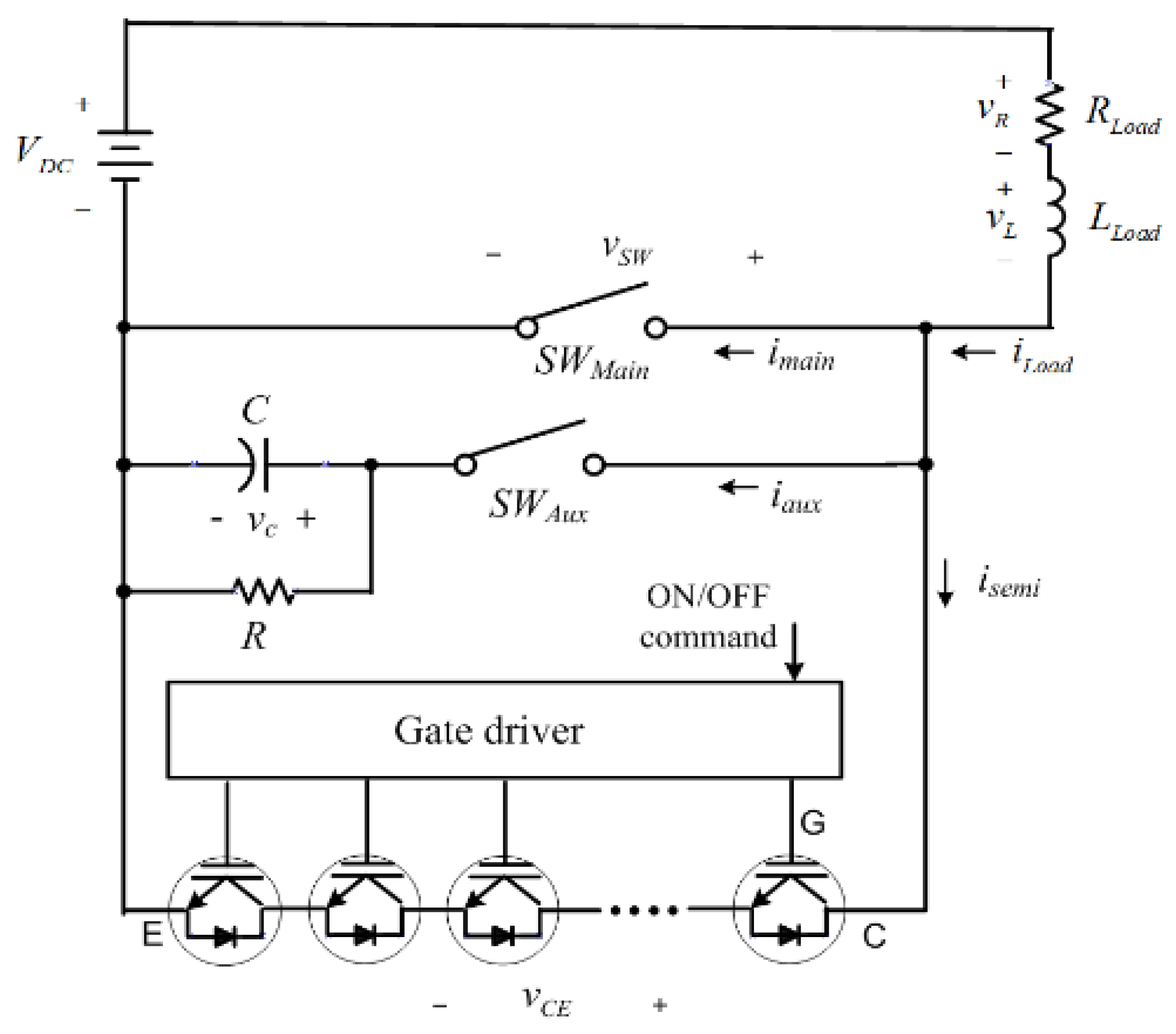
The concept of the power circuit of the MVDC hybrid circuit breaker is proposed in Figure 1. The main concept is to put commutation capacitor branch in parallel to the semiconductor switch string. The circuit breaking sequence of the proposed MVDC hybrid circuit breaker is as follows. It is assumed here that the main switch (SWMain) and the auxiliary switch of the commutation capacitor branch circuit are already turned on in the initial conduction state, and the ON command is also given to the gate driver of the semiconductor switch string branch (IGBT string). Following is explanation of the proposed control sequence when breaking the circuit with proposed MVDC hybrid circuit breaker;
- ①
- When the main switch is cut off, the current flowing through the main switch is commutated to the capacitor branch circuit, and begins to charge the capacitor.
- ②
- When the capacitor is charged high enough to turn ON the semiconductor switch string branch (VCEON), the semiconductor switch string is turned ON because the gate of the semiconductor switch string is already ON.
- ③
- When it is confirmed that all of the load currents have been commutated to the semiconductor switch branch circuit, the capacitor branch circuit is turned off. Then, the capacitor is discharged through the discharge resistor (R), and the capacitor is reset.
- ④
- When the main switch is sufficiently opened and the insulation distance is secured, the semiconductor switch string is turned off to cut off the load current without arcing.
Since the withstanding voltage of the commutation capacitor used in the proposed method only needs to be secured as much as the ON drop voltage (VCEON) of the semiconductor switch string, a capacitor with a small rated voltage can be used.
2.2. Sequence Control
Figure 2 shows a control circuit for controlling the operating sequence of the MVDC hybrid circuit breaker. In Figure 2, Comparator 1 is to determine the connection and disconnection of the capacitor branch circuit, and the role of Comparator 2 is to determine ON/OFF of the semiconductor switch branch. Two current sensors detect the load current (ILoad) and the current flowing through the semiconductor switch branch circuit (Isemi). Comparator 1 compares the load current value with the threshold current value ILimit. The threshold current value is set to a positive small value. Therefore, when the load current (ILoad) does not flow initially, the output (SRelay) of the Comparator 1 is in a low state, and the contact (R1_A) of the relay is in the OFF state. When the load current increases as the circuit is turned on, the output of the Comparator 1 becomes high and the make contact (R1_A) of the relay is turned ON to connect the capacitor branch circuit. When the main switch cut off and the load current does not flow in the main switch, the output (SRelay) of Comparator 1 becomes low and separates the capacitor branch circuit.
In Figure 2, the Subtractor calculates the difference between the load current value (ILoad) and the current value flowing through the semiconductor switch branch circuit (Isemi). This value is input to Comparator 2 to compare the threshold current value (ILimit). When the current value flowing through the semiconductor switch string is close to the load current value within the error range of the threshold current value, the output (SGate) of Comparator 2 becomes low, and an OFF command is applied to the gate diver to turn off the semiconductor switch string.
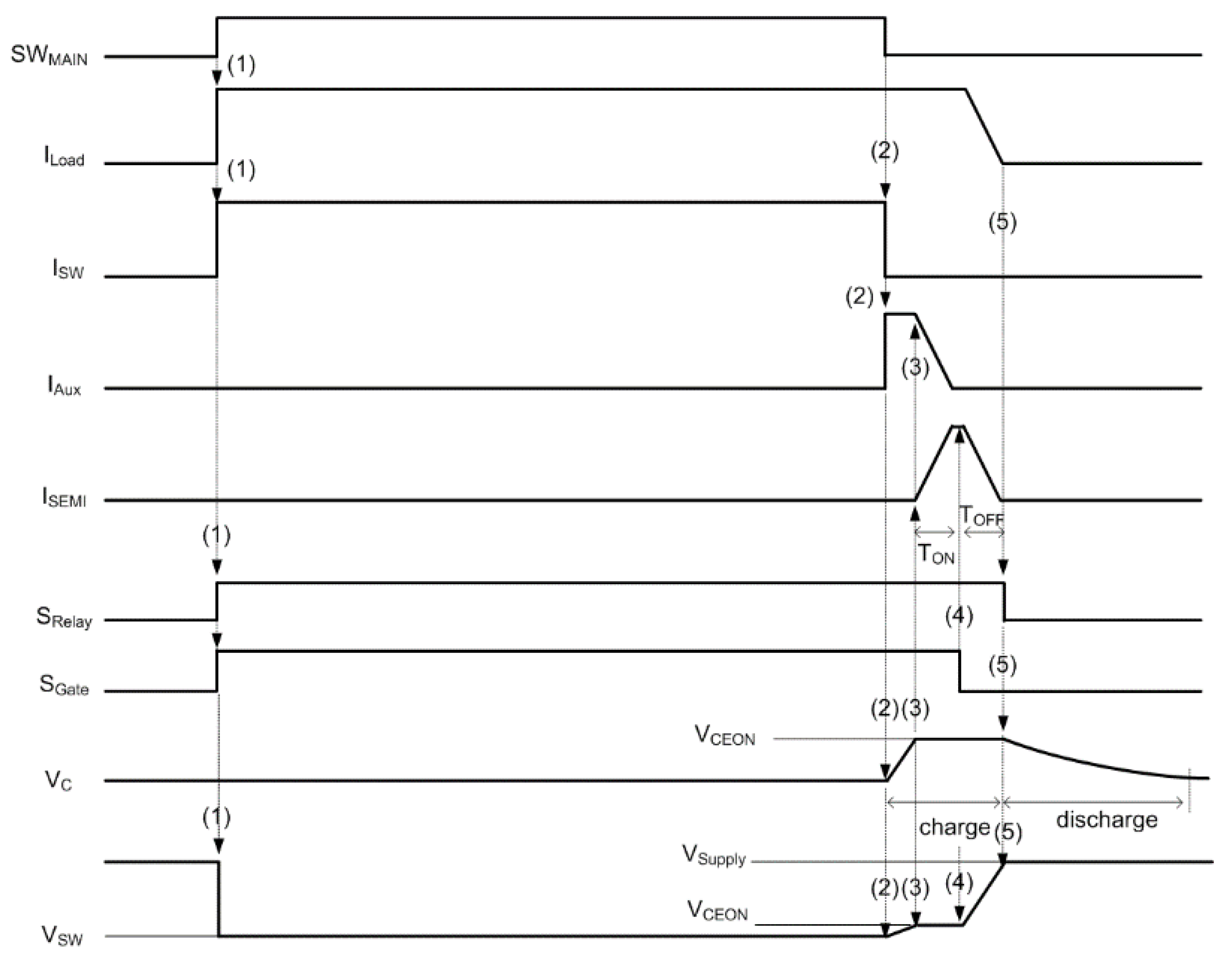
Figure 3 shows the control sequence of the MVDC hybrid circuit breaker proposed in Figure 2. Next, the proposed control sequence will be described;
- (1)
- When the main switch (SWMain) is turned on, the load current (ILoad) flows through the main switch. At this time, the current flowing through the main switch (ISW) is equal to the load current (ILoad), but the current flowing through the capacitor branch circuit (IAux) and the current flowing through the semiconductor switch branch circuit (Isemi) are still zero. Therefore, since the load current value is greater than zero, the output of the Comparator 1 becomes high, and the relay excitation coil (R1) is magnetized to turn on the make contact (R1_A) of the relay. However, the load current already flows through the main switch whose contact resistance value is almost zero, the current does not flow in the commutation capacitor branch circuit. Meanwhile, since the current flowing through the semiconductor switch branch circuit (Isemi) is zero that is certainly less than the load current value (ILoad), the output of the Comparator 2 (SGate) is in a high state to turn the semiconductor switch string ON. However, the load current already flows through the main switch whose contact resistance value is almost zero, the current does not flow through the semiconductor switch string with a large on-voltage drop (VCEON).
- (2)
- If the main switch is turned off while the load current is flowing, the load current flowing through the main switch is immediately commutated and flows to the commutation capacitor branch circuit that has already been connected through the auxiliary switch (SWAUX). Therefore, the voltage starts to rise as the capacitor is charged by the value of the load current.
- (3)
- When the voltage across the capacitor increases up to the ON voltage drop (VCEON) of the semiconductor switch string, the load current starts to bypass to the semiconductor switch string that was already ON by the gate diver. Thus, the current flowing through the capacitor branch circuit begins to decrease and the current flowing through the semiconductor switch branch circuit begins to increase. At this time, the voltage across the main switch maintains the on-voltage drop (VCEON) of the semiconductor switch string.
- (4)
- When the current value flowing through the semiconductor switch branch circuit (Isemi) is close to the load current value (ILoad) within the error range of the threshold current value, the output of the Comparator 2 (SGate) is in a low state, and an OFF command is applied to the gate diver to open the semiconductor switch string. Then, the load current flowing through the semiconductor switch branch circuit decreases with a downward slope without an arc. At this time, the voltage across the main switch starts to rise up to the power supply voltage level where the main switch is already opened enough to withstand the power supply voltage.
- (5)
- When the load current continues to decrease and the load current value becomes zero, the output (SRelay) of Comparator 1 becomes low, which turns off the relay excitation coil (R1) and turns off the relay contact (R1_A). At this time, the MVDC hybrid circuit breaker is completely cut off, and the voltage across the main switch becomes the power supply voltage level. The charge remaining in the capacitor is initialized by discharging through the discharge resistor (R).
3. Experimental Results
3.1. Experiment Conditions
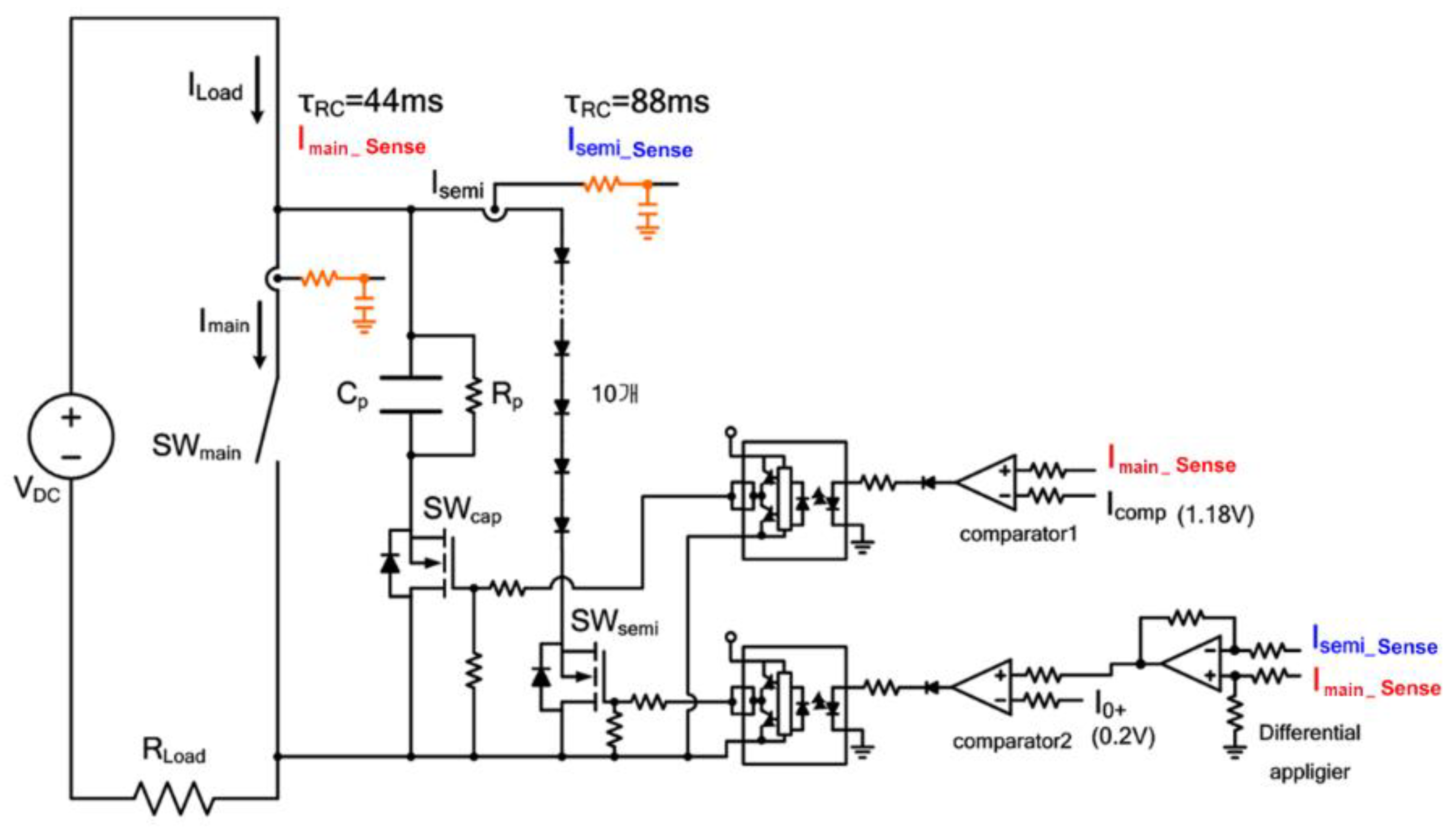
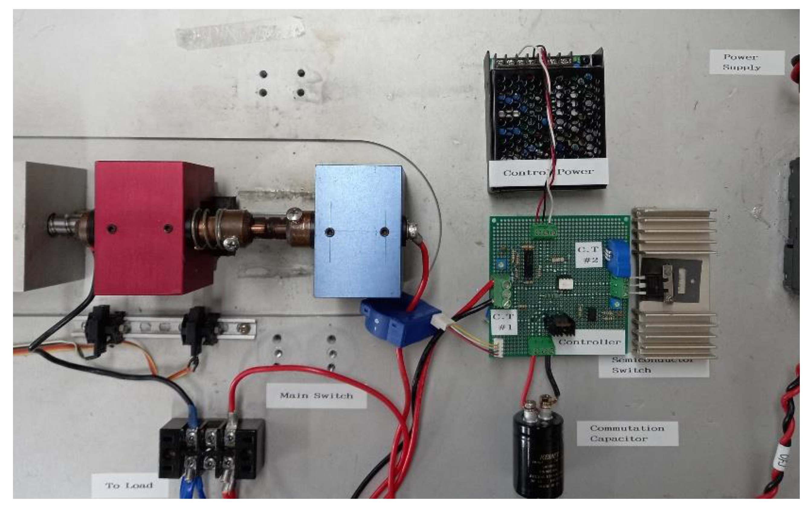
Figure 4 shows an experimental circuit designed to verify the sequence control operation of the proposed MVDC hybrid circuit breaker. Due to the constraints of the laboratory, the power circuit was scaled down. The main power supply voltage was lowered to 400 V and the resistance load value was set to 40 Ω. Therefore, in the normal conduction state, the load current is 10 A. The semiconductor switch string (SWSEMI) that is composed of several semiconductor switches was replaced by connecting one semiconductor switch (IGBT) and several diodes in series for convenience. By doing this, the voltage required to turn on the semiconductor switch (VCEON) can be increased by the forward voltage drop of all diodes connected in series (about 1 V per diode), making it as if several semiconductor switches are serially operating.
In the experimental circuit, the semiconductor switch string is named SWSEMI, and the auxiliary switch is named SWCAP. For convenience, a FET switch was used for the auxiliary switch (SWCAP). In the process of detecting the main switch current and the current flowing through the semiconductor switch string in the experimental circuit, low pass filters were used to reduce noise and cause a time delay. Comparator 2 is an element that determines the timing of ON/OFF of the semiconductor switch string (SWSEMI). In particular, the time delay of the current sensor plays an important role when determining the OFF timing.
In this experiment, the time constant of the current detection flowing through the semiconductor switch branch circuit (Isemi_sense) was increased by about 2 times than the time constant of the main switch current detection (Imain_sense). Here, the time constant was set rather large for convenience. However, by lowering the value of the time constant to reduce the time delay, optimized circuit breaking characteristics can be obtained.
Figure 5 shows a photograph of the experimental setup for the proposed MVDC hybrid circuit breaker. The main switch is composed of two bronze electrodes driven by geared step motor so that the opening speed can be controlled by the step motor. The maximum opening speed of the moving electrode is 80 mm/sec. By varying the opening speed of the main switch, the characteristics of the proposed hybrid circuit breaker can be exploited. Current transducer 1 (C.T #1) is for main switch current detection (Imain_sense), and current transducer 2 (C.T #1) is for semiconductor switch current detection (Isemi_sense).
3.2. Experiment Result
The sequence control operation of the proposed MVDC hybrid circuit breaker considers the time point of five stages according to the switching state. The five-step time points according to the operation sequence are as follows. These five-steps operations are automatically performed by the proposed analog controller as the main switch is turned ON/OFF.
- Circuit making procedure
- Step (1)
- Main switch (SWMain) ON:The load current (ILoad) flows through the electrical contact type main switch.
- Step (2)
- Semiconductor switch branch circuit (SWSEMI) ON:When the load current increases and the output of Comparator 2 becomes high, an ON signal is applied to the gate of the semiconductor switch string (SWSEMI). However, the load current already flows through the main switch whose contact resistance value is almost zero, and the current does not flow into the semiconductor switch string with a large drop in on-voltage.
- Step (3)
- Turn on the auxiliary switch (SWCAP):When the load current value (ILoad) is greater than the set value (ICOMP), the output of Comparator 1 is also high, and an ON command is applied to the auxiliary switch (SWCAP). However, the load current already flows through the main switch whose contact resistance value is almost zero, the current does not flow toward the capacitor branch circuit.
- Circuit breaking procedure
- Step (4)
- Main switch (SWMain) OFF:When the main switch is cut off, the load current flowing through the main switch is immediately commutated to the capacitor branch circuit that has already been connected through the auxiliary switch (SWCAP). Therefore, the voltage starts to rise as the capacitor is charged by the value of the load current.When the voltage across the capacitor increases up to the ON voltage drop (VCEON) of the semiconductor switch string (SWSEMI), the load current starts to commutate to the semiconductor switch string that has already been turned on by the gate diver. That is, the current flowing through the capacitor branch circuit begins to decrease, and the current flowing through the semiconductor switch branch circuit begins to increase. At this time, the voltage across the main switch maintains the on-voltage drop of the semiconductor switch string.
- Step (5)
- Semiconductor switch (SWSEMI) OFF:When the current value flowing through the semiconductor switch (Isemi) reaches to the load current value within the error range of the threshold current value (ILimit), the output of the Comparator 2 becomes low, and an OFF command is applied to the gate diver to turn the semiconductor switch string OFF. At this time, the voltage across the main switch starts to rise to the level of the power supply voltage.When the load current continues to decrease and becomes smaller than the set value (ICOMP), the output of Comparator 1 becomes low and the auxiliary switch (SWCAP) is turned off. Then, the charge remaining in the capacitor is discharged through the discharge resistor (R).The MVDC hybrid circuit breaker is completely OFF and the voltage across the main switch becomes the power supply voltage level.
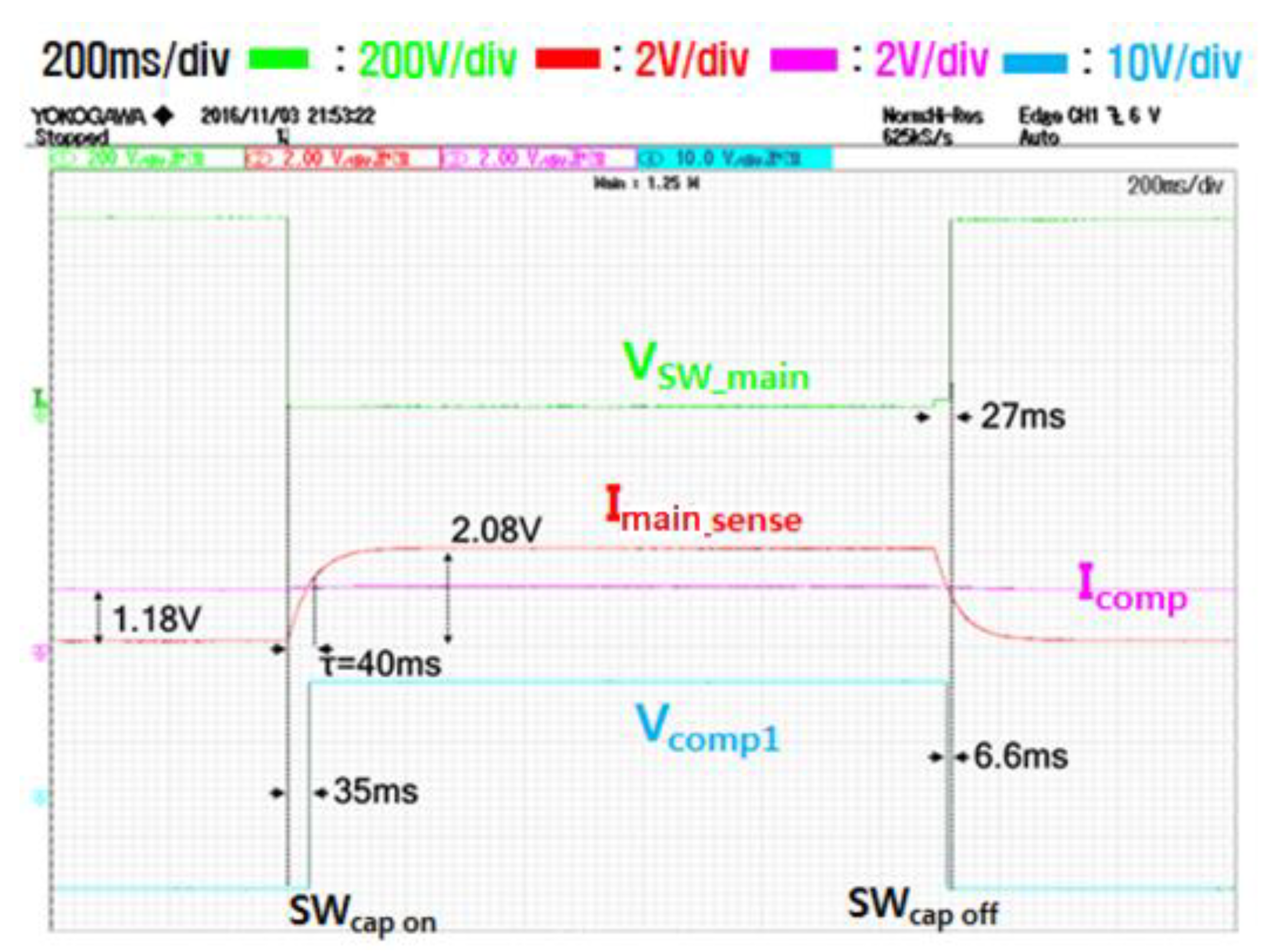
Figure 6 describes the output of Comparator 1 (Vcomp1) to turn on/off the capacitor branch circuit according to ON/OFF state of the main switch. When the main switch is turned on to make the circuit, the voltage across the main switch rapidly becomes zero, and the current flowing through the main switch rises to the value of the load current. However, the main switch current detection value (Imain_sense) increases slowly with a time constant of about 44 ms by the LPF. Since the main switch current detection value according to the full load current is set to 2.08 V, it takes about 35 ms for the main switch current detection value to reach the comparison value of 1.18 V. In other words, about 35 ms after the load current starts flowing to the main switch, the output of Comparator 1 becomes high, and the capacitor branch circuit is connected.
When the main switch turned off to break the circuit, the current flowing through the main switch becomes rapidly zero as it is commutated to the capacitor branch circuit and semiconductor switch, but it takes about 20 ms for the main switch current detection value (Imain_sense) to decrease from 2.08 V to 1.18 V of the comparison value. Therefore, about 20 ms after turning off the main switch, the output of Comparator 1 becomes low and the capacitor branch circuit is separated.
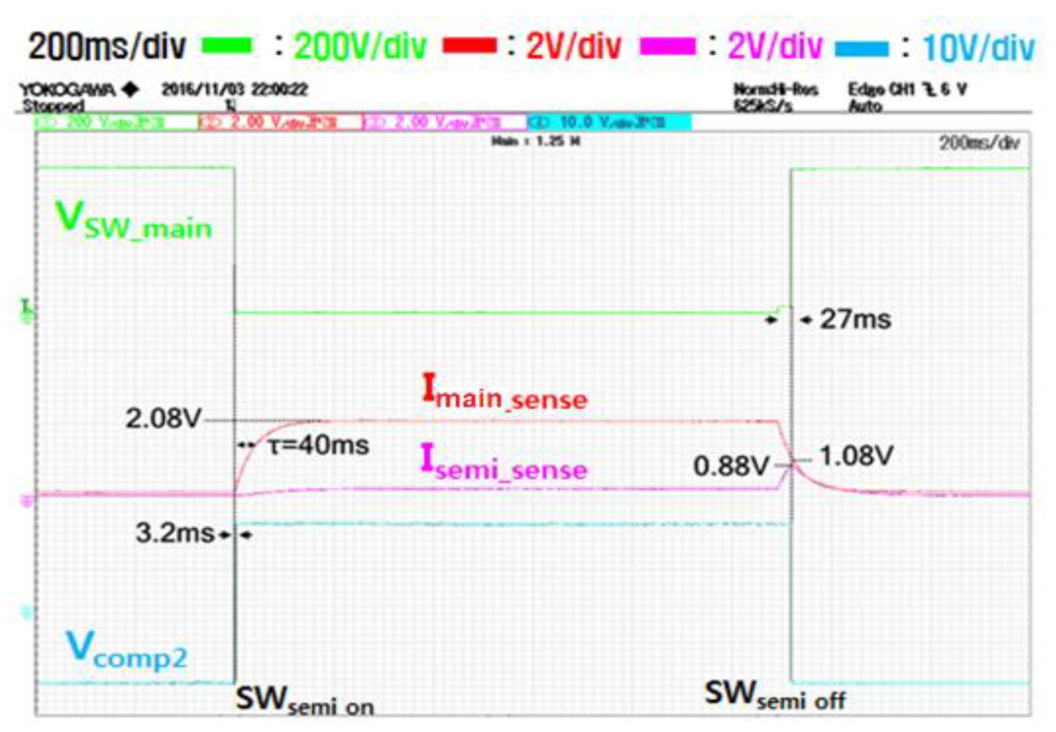
Figure 7 explains the output of Comparator 2 (Vcomp2) to turn on/off the semiconductor switch string according to the conditions of the current flowing through the main switch branch and the current flowing through the semiconductor switch string. When the main switch is turned on to make the circuit, the current flowing through the main switch (Imain) rises to the value of the load current. However, since the semiconductor switch string is initially in the OFF state, the current flowing through the semiconductor switch string branch (ISEMI) is zero. Therefore, when the current detection value of the main switch (Imain_sense), which rises with a time constant of 44 ms by the LPF, rises and exceeds the threshold (0.2 V in this case), the output of the Comparator 2 becomes high and the semiconductor switch string is turned on. However, the load current flows only to the main switch branch with a low resistance value and does not flow to the semiconductor switch string branch.
When the main switch is turned off to break the circuit, the current flowing through the main switch branch is commutated by the commutation capacitor, and transfers to a semiconductor switch string branch and rapidly becomes zero. However, the current detection value of the main switch branch (Imain_sense) decreases gradually with a time delay of about 44 ms by the LPF. On the other hand, the current detection value flowing through the semiconductor switch string branch (ISEMI_sense) rises more slowly with a time delay with a time constant of 88 ms, which is twice of that. Due to this difference in time constant, after the load current flowing through the main switch branch transfers to the semiconductor switch string, there is a certain time delay and later the output of the Comparator 2 (Vcomp2) goes low, and the semiconductor switch string is turned off to complete arcless cutoff.
During the breaking sequence of the circuit, the time elapsed to finally turn off the semiconductor switch string after the current flowing through the main switch branch transferred to the semiconductor switch branch is a major factor that determines the trip time, and this time delay can be adjusted by varying the time constant of the LPFs.
In Figure 6 and Figure 7, it can be seen that the point at which the output state of Comparator 1 goes low is faster than the point at which the output state of Comparator 2 goes low. That is to say, the point when the output state of Comparator 2 goes low is about 27 ms after turning the main switch OFF, whereas the point when the output state of Comparator 1 goes low occurs about 20 ms after turning the main switch OFF. This is to initialize commutation capacitor by completely separating the capacitor branch circuit before the circuit break is totally terminated (about 7 ms here). This difference in time can be adjusted by setting different values of Icomp (=1.18 V), which is the comparison reference value of Comparator 1.
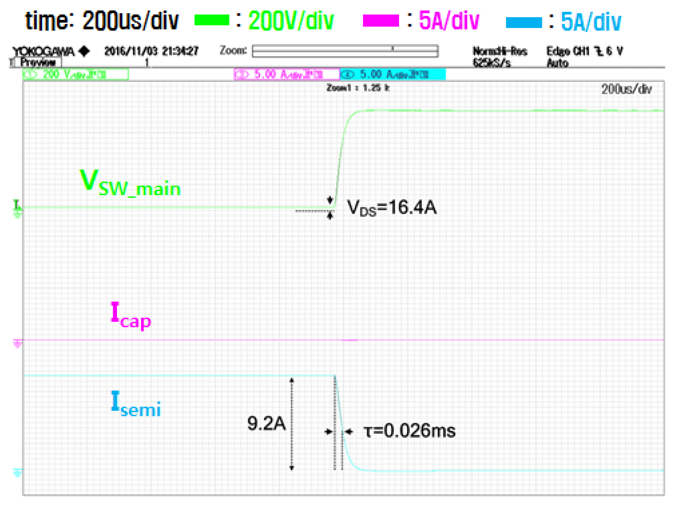
Figure 8 shows some important experimental waveforms of each branch’s current and voltage across the main switch after turning off the main switch during breaking the circuit. Because of a limit to the channels that can be captured with the scope, the experimental waveforms displayed with two separate screens. In Figure 8a, the upper waveform shows the voltage across the main switch (Vsw_main), the middle waveform shows the current flowing through the main switch (Imain), and the lower waveform shows the current flowing through the capacitor branch and semiconductor switch branch (Icap + Isemi). As the main switch turns off, it can be seen that the load current flowing through the main switch is commutated into the capacitor branch and the semiconductor switch branch.
On the other hand, Figure 8b shows separate waveforms of the currents flowing through the capacitor branch (Icap) and the current flowing through the semiconductor switch branch (Isemi). In Figure 8b, when the main switch is turned off, the commutation capacitor is charged by the capacitor charging current (Icap) and the voltage at both ends of the main switch (Vsw_main) rises above a certain level (VCEON = 16.4 V in this experiment) to turn on the semiconductor switch string (SWSEMI). Since the gate of the semiconductor switch string already turned on, it can be seen that the current is bypassed to the semiconductor switch branch. Here, the time when the load current flowing through the main switch is completely decreased to zero is about 0.1 ms. When the current is bypassed to the semiconductor switch branch, the voltage across the main switch maintains the on-voltage drop of the semiconductor switch string (VCEON = 16.4 V), and the load current flows through the semiconductor switch branch.
Figure 9 shows some important experimental waveforms of each branch currents and voltage across the main switch when the output state of Comparator 2 goes low after about 27 ms after the main switch is turned off, when an OFF signal is applied to turn off the semiconductor switch string. The capacitor current and voltage are already zero and the capacitor branch is disconnected. The voltage across the mechanical main switch rises, and the load current through the semiconductor switch decreases and extinguishes without arc. The extinguishing time is about 0.1 ms.
In conclusion, in the experiment of the proposed MVDC hybrid circuit breaker, it can be seen that the summation of the time required for current commutation when the main switch is turned off and the time required for turn-off the semiconductor switch string itself after finishing the current commutation is about 0.2 ms in total. The total breaking time of the proposed hybrid switch can be further affected by the mechanical opening speed of the main switch and the auxiliary switch. In other word, the opening time of the main switch and the auxiliary switch must be considered to the capacitor commutation time and the semiconductor turn-off time to get the total trip time of the proposed MVDC hybrid switch.
4. Conclusions
In this paper, a new power circuit structure for current commutation of a MVDC hybrid circuit breaker was proposed, and the operation of sequence controller for the proposed MVDC hybrid circuit breaker was verified by a scaled-down experimental hybrid circuit breaker. As a result of the experiment, the sequence controller of the proposed MVDC hybrid circuit breaker can be seen that the summation of the time required for current commutation when the circuit is cut off and the time required for turning-off the semiconductor switch is under 0.2 ms.
However, even after the current commutation is completed, the turning-off of the semiconductor switch string must be delayed until the insulation distances of the main switch and the auxiliary switch are secured. Since the high-speed contact switch normally takes about 2 ms to secure the insulation distance, the total trip time can be designed within 2.2 ms that proves the validity of the proposed sequence controller for the proposed MVDC hybrid circuit breaker. Especially switching speed is very important in MVDC applications. Long trip time allows the current reaches intolerable values, leading to oversized solutions.
In the future, it is expected that more practical breaking characteristics can be identified through experiments on scaled-up power circuits.
Funding
This work was supported in part by Basic Science Research Program through the National Research Foundation of Korea (NRF) funded by the Ministry of Education (Grants No. 2016R1D1A3B01008279).
Acknowledgments
The author appreciates Dan Bi Ryu and Yong Joong Kim of their supports of experiments.
Conflicts of Interest
The author declares no conflict of interest.
References
- Flourentzou, N.; Agelidis, V.G.; Demetriades, G.D. VSC-Based HVDC Power Transmission Systems: An Overview. IEEE Trans. Power Electron. 2009, 24, 592–602. [Google Scholar] [CrossRef]
- Raza, A.; Dianguo, X.; Xunwen, S.; Weixing, L.; Williams, B.W. A Novel Multiterminal VSC-HVdc Transmission Topology for Offshore Wind Farms. IEEE Trans. Ind. Appl. 2016, 53, 1316–1325. [Google Scholar] [CrossRef]
- Yang, J.; Fletcher, J.E.; O’Reilly, J. Short-Circuit and Ground Fault Analyses and Location in VSC-Based DC Network Cables. IEEE Trans. Ind. Electron. 2012, 59, 3827–3837. [Google Scholar] [CrossRef] [Green Version]
- Lee, S.; Kim, H. A study on Low-Voltage DC circuit breakers. In Proceedings of the 2013 IEEE International Symposium on Industrial Electronics, Taipei, Taiwan, 28–31 May 2013; pp. 1–6. [Google Scholar]
- ABB Circuit-Breakers for Direct Current Applications; ABB SACE SPA: Bergamo, Italy, 2007; pp. 1–56.
- Jinzenji, T.; Kudoa, T. A GTO DC circuit breaker controlled by a single-chip microcomputer. IEEE Trans. Ind. Electron. 1985, IE-32, 204–209. [Google Scholar] [CrossRef]
- Zhang, L.; Woodley, R.; Song, X.; Sen, S.; Zhao, X.; Huang, A.Q. High current medium voltage solid state circuit breaker using par-alleled 15kV SiC ETO. In Proceedings of the 2018 IEEE Applied Power Electronics Conference and Exposition (APEC), San Antonio, TX, USA, 4–8 March 2018; pp. 1706–1709. [Google Scholar]
- Shukla, Z.A.; Demetriades, G.D. A survey on hybrid circuit-breaker topologies. IEEE Trans. Power Deliv. 2014, 30, 627–641. [Google Scholar] [CrossRef]
- Kim, W.; Kim, Y.-J.; Kim, H. Arc Voltage and Current Characteristics in Low-Voltage Direct Current. Energies 2018, 11, 2511. [Google Scholar] [CrossRef] [Green Version]
- Kim, H. Gate Drive Controller for Low Voltage DC Hybrid Circuit Breaker. Energies 2021, 14, 1753. [Google Scholar] [CrossRef]
- Meyer, J.-M.; Rufer, A. A DC Hybrid Circuit Breaker With Ultra-Fast Contact Opening and Integrated Gate-Commutated Thyristors (IGCTs). IEEE Trans. Power Deliv. 2006, 21, 646–651. [Google Scholar] [CrossRef]
- Callavik, M.; Blomberg, A. The Hybrid HVDC Breaker. ABB Grid Syst. Tech. Pap. 2012, 361, 143–152. [Google Scholar]
- Hafner, J. Proactive hybrid HVDC breakers—A key innovation for reliable HVDC grids. In Proceedings of the CIGRE Bologna Symposium, Bologna, Italy, 13–15 September 2011; pp. 1–8. [Google Scholar]
- Wang, Y.; Marquardt, R. Future HVDC-grids employing modular multilevel converters and hybrid DC-breakers. In Proceedings of the 2013 15th European Conference on Power Electronics and Applications (EPE), Lille, France, 2–6 September 2013; pp. 1–8. [Google Scholar]
- Wen, W.; Huang, Y.; Sun, Y.; Wu, J.; Al-Dweikat, M.; Liu, W. Research on Current Commutation Measures for Hybrid DC Circuit Breakers. IEEE Trans. Power Deliv. 2016, 31, 1456–1463. [Google Scholar] [CrossRef]
- Chen, Z.; Yu, Z.; Zhang, X.; Wei, T.; Lyu, G.; Qu, L.; Huang, Y.; Zeng, R. Analysis and Experiments for IGBT, IEGT, and IGCT in Hybrid DC Circuit Breaker. IEEE Trans. Ind. Electron. 2018, 65, 2883–2892. [Google Scholar] [CrossRef]
- Zhang, X.; Yu, Z.; Zeng, R.; Huang, Y.; Zhao, B.; Chen, Z.; Yang, Y. A State-of-the-Art 500-kV Hybrid Circuit Breaker for a dc Grid. IEEE Ind. Electron. Mag. 2020, 14, 15–27. [Google Scholar] [CrossRef]
Figure 1.
Concept of the proposed medium voltage DC (MVDC) hybrid circuit breaker.

Figure 2.
Sequence controller of the proposed MVDC hybrid circuit breaker.

Figure 3.
Switching sequence of the proposed MVDC hybrid circuit breaker.

Figure 4.
Experimental circuit of the proposed MVDC hybrid circuit breaker.

Figure 5.
Photograph of experimental setup for the proposed MVDC hybrid circuit breaker.

Figure 6.
Output of Comparator 1 (Vcomp1) to turn on/off the capacitor branch circuit.

Figure 7.
Output of Comparator 2 (Vcomp2) to turn on/off the semiconductor switch.

Figure 8.
Important current and voltage waveforms during breaking the circuit.

Figure 9.
Experimental waveform of each part when the output state of Comparator 2 goes low.

Table 1.
Pros and cons of typical commutation method in hybrid circuit breakers.
| Commutation Method | Natural Commutation | Proactive Commutation | Resonance Commutation | Proposed Commutation |
|---|---|---|---|---|
| Commutating measures | Arc initiation voltage between the contacts |
|
|
|
| Breaking arc | Severe | No | Mild: 1~5 ms | No |
| Conduction loss | No | High | No | No |
| Voltage level | LVDC | MVDC/HVDC | MVDC | MVDC/HVDC |
| Reliability/ Robustness | Low: aging by arc | Middle: Electronic control | Middle: Electronic control | High: Passive operation |
| Major fault | Contact fusing or blown up by sustained arc fault | LCS broken by heating | Commutation fail because of aged capacitor | Commutation fail because of aged capacitor |
| Remark | Variation of arc ignition voltage: 10~50 V | Linear operation LCS switch is important | Resonant current should be higher than fault current | Capacitor is exponentially increase by fault current |
Publisher’s Note: MDPI stays neutral with regard to jurisdictional claims in published maps and institutional affiliations. |
© 2021 by the author. Licensee MDPI, Basel, Switzerland. This article is an open access article distributed under the terms and conditions of the Creative Commons Attribution (CC BY) license (https://creativecommons.org/licenses/by/4.0/).
Share and Cite
MDPI and ACS Style
Kim, H. Capacitor Commutation Method for MVDC Hybrid Circuit Breakers. Designs 2021, 5, 28. https://0-doi-org.brum.beds.ac.uk/10.3390/designs5020028
AMA Style
Kim H. Capacitor Commutation Method for MVDC Hybrid Circuit Breakers. Designs. 2021; 5(2):28. https://0-doi-org.brum.beds.ac.uk/10.3390/designs5020028
Chicago/Turabian StyleKim, Hyosung. 2021. "Capacitor Commutation Method for MVDC Hybrid Circuit Breakers" Designs 5, no. 2: 28. https://0-doi-org.brum.beds.ac.uk/10.3390/designs5020028