Condition Assessment of Reinforced Concrete Bridges: Current Practice and Research Challenges


Department of Civil and Environmental Engineering, Western University, London, ON N6A 3K7, Canada
*
Author to whom correspondence should be addressed.
Infrastructures 2018, 3(3), 36; https://0-doi-org.brum.beds.ac.uk/10.3390/infrastructures3030036
Submission received: 14 August 2018
/
Revised: 4 September 2018
/
Accepted: 8 September 2018
/
Published: 14 September 2018
Abstract
:One quarter of bridges in Canada and the United States need repair. The present study provides a critical overview of the state-of-the-art existing condition assessment techniques for reinforced concrete bridges, with an emphasis on current practice in North America. The techniques were classified into five categories, including visual inspection, load testing, non-destructive evaluation, structural health monitoring, and finite element modelling. The potential applications of these technologies are discussed and compared, highlighting their primary advantages and limitations. The review revealed that quantitative assessment could be effectively achieved using several complementary technologies. It is shown that there is need for concerted research efforts to achieve automated data collection and interpretation analyses. Also, the configuration of monitoring systems was found to be paramount in effectively assessing bridge performance parameters of interest. The study suggests appropriate investigation methods for some bridge deterioration mechanisms. Knowledge gaps and challenges in this field are outlined in order to motivate further research and development of these technologies.
1. Introduction
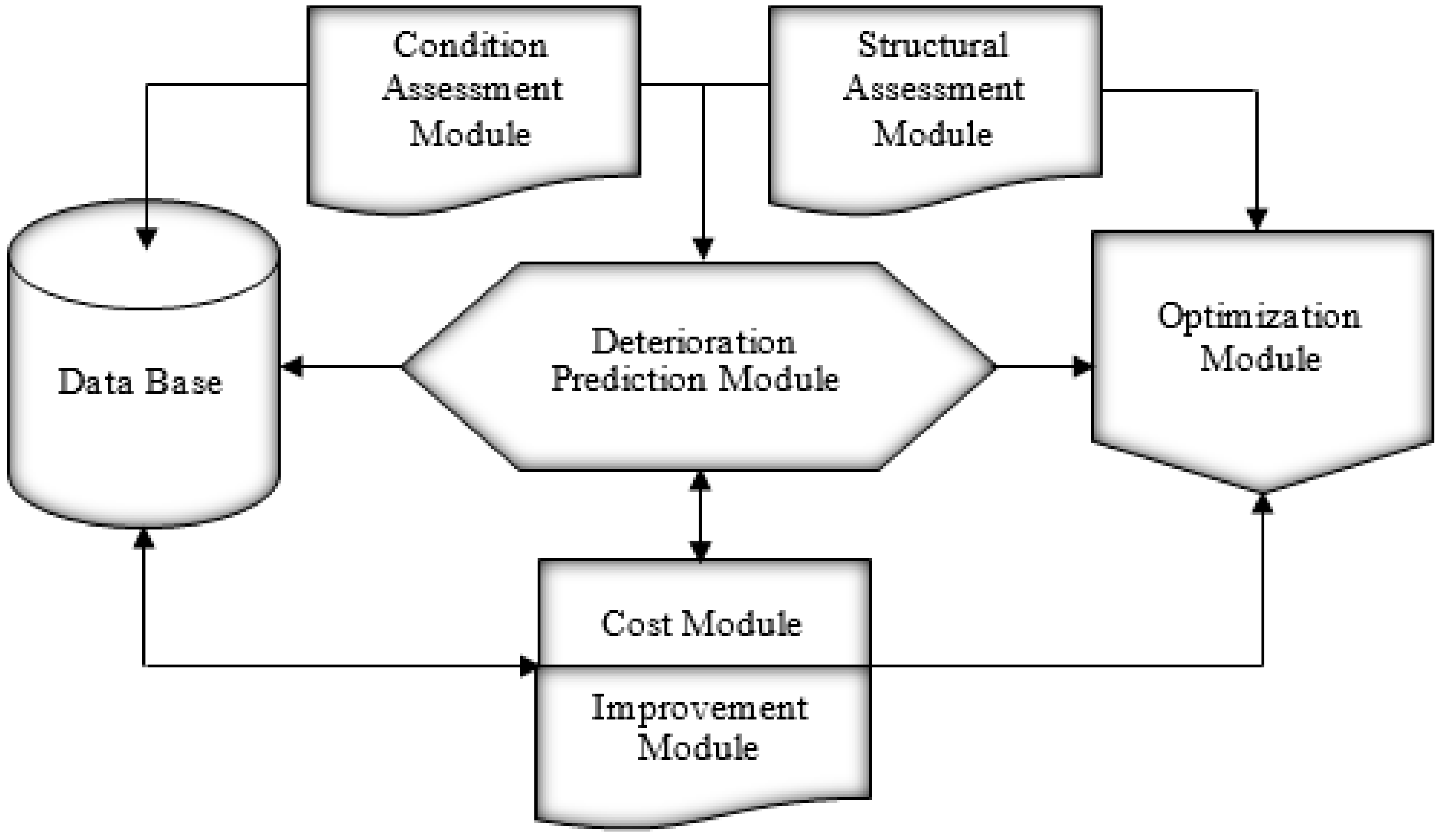
Bridge failures can be catastrophic, both in terms of human life and economic loss. According to the Canadian infrastructure report card (2016), 26% of bridges are in fair, poor or very poor condition, and US $50 billion needs to be invested for bridge replacement and maintenance. Likewise, about 25% of bridges in the USA are either structurally deficient or functionally obsolete, and $70.9 billion is needed to address their maintenance [1]. Reinforced concrete (RC) bridges often deteriorate due to ageing, materials and construction defects, exposure to aggressive environments, lack of ductility, and excessive loads. The distinction among their major degradation causes is purely qualitative since such mechanisms can act in synergy. Different deterioration processes lead to different types of defects, which represent the main challenge in bridge inspection programmes. In addition, fire is one of the most severe hazards to which RC bridges may be subjected during its service life. Bridge management systems (BMSs) have been developed to assist decision makers in maximizing the safety, serviceability, and functionality of bridges within available budgets. The basic components of a BMS are illustrated in Figure 1. The architecture of a typical BMS consists of a database, condition and structural assessment modules, a deterioration prediction module, a lifecycle cost module, and a maintenance optimization module. The database stores inventory and appraisal data. The condition assessment module evaluates the existing health condition of the bridge(s). The deterioration prediction module estimates the future condition of bridge components. The life-cycle cost module calculates agency and user costs for various maintenance alternatives. The optimization module determines the most cost-effective maintenance strategies.
Reliable bridge condition assessment (BCA) has become vital to predicting the future performance and optimizing bridge maintenance, rehabilitation and replacement (MR&R) needs. Visual inspection is the default bridge inspection methodology, yet its results heavily depend on the expertise and judgment of bridge inspectors, yielding primarily qualitative and subjective results. Advanced BCA techniques are evolving rapidly and have reached a certain level of maturity. An extensive literature survey indicates that there is a considerable number of studies on specific assessment techniques. For instance, there has been significant focus in using non-destructive evaluation technologies for detecting several deterioration indicators and load testing techniques for determining safe loading levels. The use of various structure health monitoring systems for sensing structural performance and finite element modelling for numerically predicting bridge reliability are also gaining popularity. However, there is no single study in the literature that surveys, in a systematic and rigorous manner, the state-of-the-art work on the entire BCA field. Therefore, there is need to understand how the assessment techniques, as they pertain to decision-making, have evolved and what is their present state. The present study provides a concise critical review of achievements on RC BCA methods to determine prospects for improvement and to delineate key challenges that need concerted future research efforts. Thus, a significant gap in the body of knowledge of RC bridge assessment field would be filled.
2. Review Objectives
The main goal of the present study is to elucidate upon the current state-of-the-art techniques of RC BCA, with emphasis on the current practice in Canada and the United States. To achieve this goal, the following specific objectives are pursued:
- Delineate recent research efforts on the available techniques and investigate the versatility of their applications;
- Define the strengths, limitations, and challenges associated with the application of each technique;
- Identify knowledge gaps for further research; and
- Formulate recommendations towards the selection of appropriate assessment techniques so as to identify specific deterioration types.
3. Review Methodology
The methodology adopted to achieve the review objectives is as follows:
- Developing a structured framework for conducting a comprehensive literature review on RC BCA based on a vast amount of papers published;
- Using this framework to gain an understanding of the current state of the RC BCA research field; and
- Developing a conceptual framework identifying areas of concern with regard to RC BCA techniques.
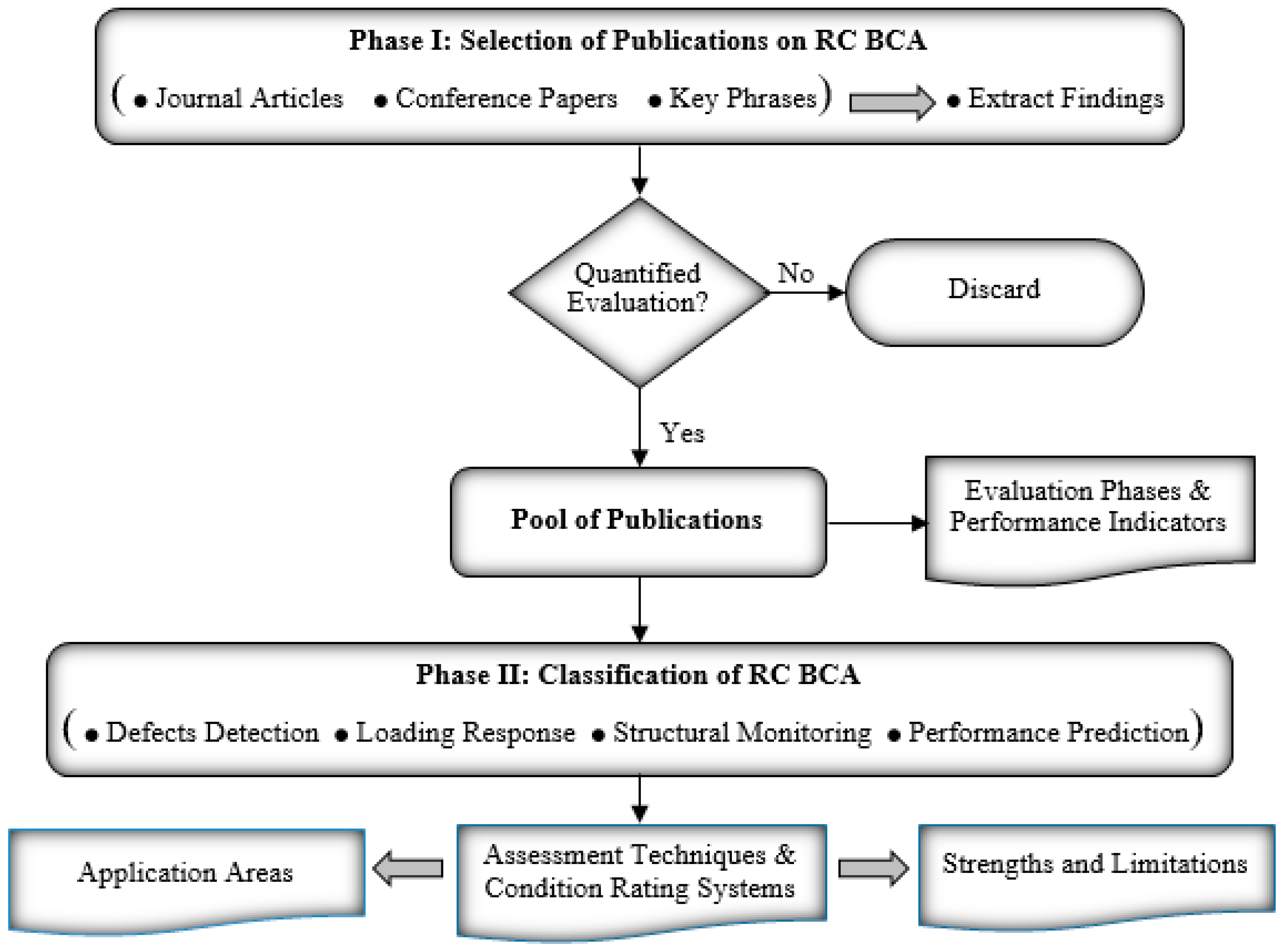
Figure 2 illustrates the developed methodological framework for implementing the review. It consists of two phases in which the first phase is the search for and selection of papers to include in the review and the second phase is the classification of the papers. The first phase started by collecting a comprehensive range of recent research on BCA. The articles were carefully selected from eight diverse academic journals within the domain of bridge construction and management in an attempt to capture recent and relevant developments. Leading research conferences on the topic were also considered in a similar manner. The articles were searched using key phrases, such as “RC bridge assessment” and “RC bridge condition rating”. This process initially identified 197 papers. The retrieved articles were further examined to extract their main findings and emphasis. Articles whose primary focus was not based on quantitative evaluation were discarded. Accordingly, the final survey qualitatively aggregates the results of a selected set consisting of 158 research studies, among which 70% were published over the last five years. The second phase started by exploring the performance indicators of RC bridges. The techniques were then classified into categories and each article was evaluated so as to be defined into the relevant category. The techniques of each category were discussed to identify their key application areas, principal strengths, and limitations. Finally, a conceptual framework was developed to address the challenges and technology gap that need further research and development and to formulate recommendations for the selection of appropriate technologies.
4. Bridge Performance Indicators
Bridge performance indicators include scour assessment, fatigue assessment, seismic assessment, and condition assessment including load carrying capacity. For a majority of RC bridges spanning watercourses or located in flood plains, failures are attributed to scour damage, which is difficult to detect in real time. Scour is a common soil-structure interaction problem. Scour reduces the stiffness of foundation systems and can cause bridge piers to fail without warning. Continuous changes in climate and the increasing frequency of flooding has led to a higher risk of such bridge failures. Several studies investigated the scour mechanism and how to predict its depth [2,3], and various types of instrumentation have been developed to measure a response of a bridge to scour (e.g., tiltmeters and accelerometers). However, appropriate preventive measures are difficult to apply when scour damage is detected. Therefore, scour monitoring is an important topic for transportation owners, especially during high-flood events and in coastal areas. Currently, there are research efforts investigating scour monitoring using changes in a bridge structural dynamic properties [4].
Loads caused by short-term traffic, variable long-term loads, and wind could lead to fatigue failure in bridges. Generally, two types of fatigue loading can result in different failure characteristics: low-cycle fatigue, in which the load is applied at high stress levels for a relatively low number of cycles; and high-cycle fatigue corresponding to a large number of cycles at lower stresses [5]. Fatigue failure modes could be classified as compression, bending, shear or bonding failure. The fatigue life of a bridge depends as much on the stress levels as on the stress range and the number of loading cycles. However, several models have been developed for bridge fatigue reliability assessment and the prediction of fatigue life of reinforcing steel rebar based on dynamic analysis, stress wave analysis, and finite element analysis [6].
Bridges located in areas subjected to seismic forces are commonly designed according to specific codes (e.g., performance and displacement-based design) to resist such forces without collapse [7]. However, the primary causes of bridge seismic damage include soil liquefaction, bridge age, design or construction modifications, and inelastic deformation during strong earthquakes. There are numerous studies in the literature on the seismic risk assessment of bridges. However, the inherent difficulties of upgrading existing RC bridges to current structural standards highlight the need for more research studies. For further details, Table 1 illustrates evaluation techniques of some bridge performance indicators and their related references.
It should be noted that fire resistance is the duration during which a bridge member exhibits acceptable performance with respect to structural integrity, stability and heat transmission. While provision for appropriate fire safety measures is a major design requirement in buildings, essentially no structural fire safety provisions for bridges exist [29]. More deatails can be found in Naser and Kodur [29] and Garlock et al. [30].
5. Bridge Condition Assessment Approaches
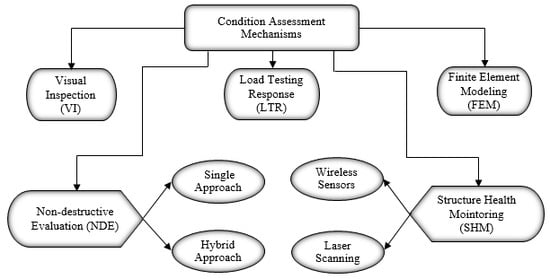
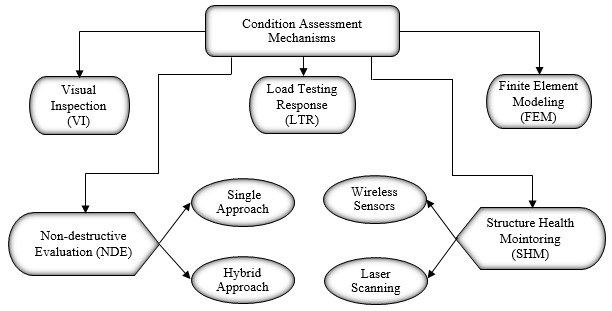
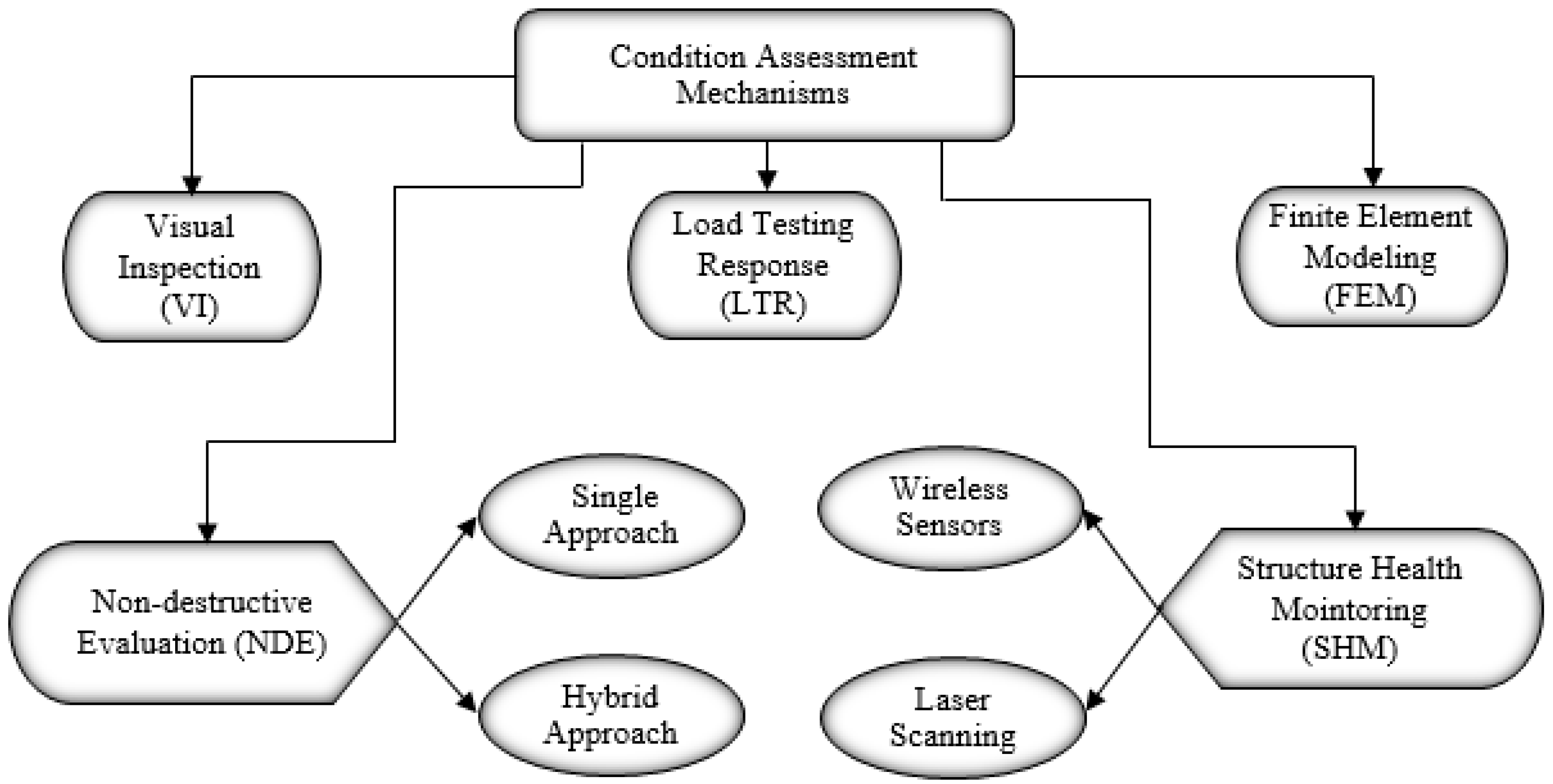
The condition assessment of an existing RC bridge aims at determining whether the bridge will function safely over a specified residual service life. Guidelines for assessment of existing bridges have been developed in many countries. They are commonly separated in phases, starting with a preliminary evaluation, followed by a detailed investigation, expert investigation, and finally an advanced assessment, depending on the structural condition of the investigated bridge [5]. Based on the different applications of the selected articles, as defined by their original authors, it was decided to classify the relevant techniques into five categories as shown in Figure 3. Each category is investigated herein to frame its knowledge gaps and highlight its research needs.
5.1. Visual Inspection
Visual inspection (VI) is the primary component of all existing BMSs. In Canada and the United States, routine VI is often conducted within 24-month intervals depending on the condition of the bridge (often coded by infrastructural agencies manuals and procedures). Enhanced inspection to access all areas of bridges over 30 years old are typically done with a maximum six years interval, while emergency detailed inspection should be carried out immediately when a component contributing to the overall bridge stability has failed, in case of imminent failure, or when public safety is at risk. The use of bridge inspection reporting software has been explored by several asset management software developers. A bridge inspection software typically consists of interactive forms that retrieve customized inspection guidelines and relevant historic bridge inspection data, capture bridge evaluation data, and automatically associate the captured information with the bridge components, making the bridge inspection documentation intuitive [31].
Research results indicate that assessing a bridge condition by VI alone is unreliable, being unable to identify correctly the repair priorities [32]. Although the qualifications and experience of those leading bridge inspection are recognised by most inspection standards, the quality and consistency of visual inspection results greatly depend on the motivation and equipment of those conducting such inspections. In spite of the fact that VI is subjective and qualitative, it has been the dominant practice for BCA and for input parameters in deterioration models. An advantage of VI is that it involves a broad evaluation of the entire bridge and is not limited to the detection or assessment of a specific type of damage or a component of the bridge. The VI costs depend on the characteristics of the bridge and are positively correlated to the level of inspection details and frequency. The major components of VI costs belong to traffic management and labour. VI costs increase for instance in cases of underwater inspection to evaluate scour [33]. Increased awareness of the shortcomings of visual inspection has motivated advanced BCA approaches. Although more quantitative models of structural deterioration have been developed, they have yet to be incorporated in existing BMSs. Thus, the review reveals the need for unified guidelines and BCA procedures capable of using the accessible data collected during the VI process and accounting for the uncertainty and complexity associated with detailed inspection process.
5.2. Load Testing
Condition assessments for the global structure integrity of existing concrete bridges are commonly addressed through structural analysis, load testing, or a combination of methods. For instance, the reliability bridge evaluation rating process described in the AASHTO’s (American Association of State Highway and Transportation) manual [34] is based on load testing. Load testing is a procedure to determine the safe loading levels of a bridge, leading to a load rating which provides the capacity level of a bridge. Through forced static and dynamic load testing in varied load patterns, the maximum response can be detected using strain transducers placed at critical locations on the bridge. Forced vibration testing combined with system identification have been used for many decades to determine the dynamic characteristics of bridge. Load tests are broadly divided into two categories: proving load tests, which are intended as self-supporting alternatives to theoretical assessments, and supplementary load tests, which are intended to be used as an adjunct to theoretical calculations [35]. However, the load ratings can be determined by allowable stress, load factor, or load and resistance factor methods. Bridge ratings performed by all three methods follow similar basic procedure, differing primarily in the load or resistance factors in the rating equation. Although, the ratings are determined in both inventory and operating load levels, these three competing rating methods may yield different rated capacities for the same bridge [36].
Not only do older bridges deteriorate over time, but they may also not have been designed for increased load demand. Therefore, the required load capacity of an existing bridge should be determined according to the extreme load effects that the bridge will experience from actual traffic during its remaining service life. Extreme vehicle loads have been researched through methods such as probabilistic vehicle weight models, consecutive traveling vehicle models, and simulation [14]. Another practical procedure of BCA via load testing is using B-WIM (bridge-weight in motion) monitoring data where the strain measurements can evaluate the bridge condition, especially for bridges under load restriction due to distress [37]. However, it should be noted that this testing is only confined to the elastic range (assuming that a heavily overloaded truck representing ultimate load), which gives no information on the non-elastic performance at the ultimate limit state.
Bridge strains, displacements, and accelerations can be measured during load testing. Vertical displacement has been considered as the most important among various structural health parameters that could be used for predicting consequent damage or deterioration in RC bridges. For instance, deflection in RC bridges increases with reductions in stiffness when cracking of the concrete occurs. Therefore, service limit states, specified in several design codes and standards, indicate that deflections throughout the entire service life of a bridge must not exceed acceptable limits. Measuring deflections during a load test can be done using linear variable differential transducers-LVDTs, and fibre-optic or similar sensors mounted on a fixed support. While these systems have high rates of data acquisition and reasonable accuracy, it is usually difficult to install them on bridges spanning waterways, bridges with heavy traffic, and when there is need of placing the sensors in contact with an auxiliary frame linked to the ground [38]. Other options include topographical methods, hydraulic methods, and the radar interferometry system. Generally, the topographical methods have low resolution and do not provide high rates of readings, preventing their use for obtaining influence lines and accurate deflection measures. The hydraulic methods have similar drawbacks in addition to the effects of temperature on measurements, while the radar system does not directly measure deflections, which makes it difficult to apply. However, applying the geodetic technique using a robotic total station or a theodolite has been successfully used for bridges characterized by large deflections [38].
Bridge structural integrity can also be assessed by the most probable values of the structural element properties, such as the stiffness obtained using vibration measurements. For instance, Chen et al. [39] applied image processing methods and utilized the data of vibration measurements and video-based traffic monitoring to update the probability distributions of the elements’ stiffness where the most probable values served as reliable indicators of the bridge structural integrity. Wang et al. [36] assessed several existing bridge structures and recommended guidelines, established by a coordinated load testing programme and a finite element model (FEM) integrated within a structural reliability framework to determine practical bridge rating methods. However, loads experienced by bridges are often inferred from limited measurements of external conditions (e.g., ambient temperature, wind speed/direction, wave heights). Therefore, the monitoring of load testing can be combined with other technologies such as structural health monitoring methods for improved assessment of concrete bridges.
5.3. Structural Health Monitoring
Structural health monitoring (SHM) is a non-destructive in situ sensing and evaluation technique that uses multiple sensors embedded in a structure to monitor and analyze the structural response and detect anomalous behaviour in order to estimate deterioration and to evaluate its consequences regarding response, capacity, and service life. In recent years, several SHM systems have been developed and implemented to provide information for bridge maintenance strategies. Most SHM systems have similar fundamental elements: (1) measurements by sensors and instrumentation, (2) structural assessment (e.g., peak strains or modal analysis), and (3) BCA to support MR&R related decision-making [40]. The functionality of a SHM system depends on the type and number of sensors used. A monitoring system may rely on single or multiple sensor types, which can be tailored to capture a variety of physical measurements associated with loads, environmental conditions, and bridge responses [41]. A SHM system with a variety of sensor types can identify material parameters such as concrete creep, shrinkage and corrosion, environmental effects including temperature gradients and dynamic responses, such as traffic-induced vibrations [42]. Table 2 summarizes some common SHM systems to identify the most important parameters in appraising the overall stiffness and bearing capacity of a bridge structure.
5.3.1. Data Acquisition Using Sensors and Laser Scanning
Structural health monitoring systems often relied on cables to connect sensors on bridges to a centralized power and data acquisition source. These wired systems are usually very reliable and are capable of high data collection rates. However, data and power cables, along with supporting conduit installation, remain the primary implementation and cost obstacles for cabled monitoring systems [53]. Fibre-optical sensors (FOS) have been applied for strain, temperature, and vibration measurement. Fibre-optical sensors are less susceptible to electrical noise than strain gauges and accelerometers and thus, can provide distributed measurements along a bridge but their accuracy are questionable [54]. With the increased availability of wireless data networks, sustainable SHM systems have been developed so that pervasive sensor networks allow more efficient monitoring of multiple bridges and bridge segments across large areas. Wireless sensors have alleviated the cost and labour associated with cabled monitoring systems. O’Connor et al. [55] employed a wireless sensor network to measure bridge accelerations, strains and temperatures. However, limitations of using wireless sensors include constraints in power and transmission bandwidth. Solar power supply, vibration, or wind could sustain long-term wireless sensor network operations, while less relevant communication bandwidth constraints could be made by conveying less data. For instance, O’Connor et al. [55] introduced the compressed sensing data acquisition approach to achieve energy efficiency in long-term monitoring applications.
Laser scanning have been used in recent years for several health monitoring and damage detection applications of structures. Laser scanning capabilities such as texture mapped 3D point clouds can be used effectively to document quantitative information on present conditions of bridges where individual laser scans of a scene may be captured from different viewpoints to permit the creation of a complete 3D record of a damaged bridge [56]. Guldur et al. [57] developed a condition rating system of bridge components using detected and quantified surface damage from texture-mapped laser point clouds. The severity of the detected damage of each structural item was classified and assigned a numerical rating value based on the American Association of State Highway and Transportation Offficials (AASHTO) condition rating guidelines [34]. The system provides structural evaluation, giving an overall bridge condition based on major deficiencies. Zhao et al. [52] developed a bridge displacement monitoring system based on laser projection-sensing and recommended the use of long-distance laser devices with higher power and good collimation to monitor displacements in large-span bridges.
5.3.2. Common Applications of SHM Systems
Structural health monitoring applications can be deployed for load rating, short-term assessment of a specific bridge performance aspect (e.g., corrosion or scour) or for long-term monitoring to assess and track a wide range of bridge health conditions. SHM can track previously identified concerns or continuously monitor the bridge performance to detect damage before it reaches critical levels through systems that are deployed pre-emptively during the construction phase. Laory et al. [58] discussed a systematic approach to determine the appropriate number and location of sensors to configure measurement systems in which static measurement data are interpreted for damage detection of continuously monitored bridge structures. Many SHM systems have been deployed on a variety of bridge components, such as long-term monitoring of bridge abutment piles, and remote sensing of corrosion in bridge decks [59]. Integration of different SHM systems or combining them with other techniques can enhance the assessment process. Generally, a monitoring system is designed as an integrated system with all data flowing to a single database and presented through a single user interface.
For instance, Hu and Wang [60] proposed an integrated SHM system which facilitates the combination of data collection and data analysis. Wireless network sensors including accelerometers, strain gauges, and temperature sensors were utilized in a system that can continuously monitor a bridge performance under random loads, where static and dynamic structural response parameters (e.g., vibration acceleration, dynamic displacement, and dynamic strain) can be determined and analyzed. Agdas et al. [33] utilized visual inspection and wireless sensors network and recommended a hybrid evaluation technique that adopts both approaches for optimal functionality to optimize efficiency of BCA. Akula et al. [31] introduced an integration BCA system through a software called Toolkit, which allows inspectors’ access to an intelligent interpretation of SHM obtained data and to the BCA data corresponding to equivalent components recorded visually by other respondents. However, while the SHM approach is promising as an effective bridge management tool, it still needs further dedicated research to make it a simple, reliable and low-cost option to become a standard aspect in BMSs.
5.4. Non-Destructive Evaluation
Non-destructive evaluation (NDE) techniques enable detection of deterioration processes at their early stages. Non-destructive evaluation methods can be incorporated into the inspection process for example to evaluate stiffness and strength, moisture content, and hidden defects. Non-destructive evaluation is specified in some BMSs through periodical surveys or when visual inspection results indicate irregularities within the structure. Appropriate and effective use of NDE needs three requirements: (i) suitable understanding of the underlying phenomenon, (ii) deploying testing methods correctly, and (iii) applying appropriate and accurate models in the analysis to quantify the detected defects or variation of properties. However, a number of NDE techniques, which exploit various physical phenomena (e.g., acoustic, seismic, electric, thermal, and electromagnetic, etc.), have been explored as a means of improving the reliability of BCA. Generally, such techniques utilize an approach where the objective is to learn about the characteristics of the medium from its response to an applied excitation [61]. Among all bridge components, the performance of bridge decks was identified as the most important long-term bridge performance issue. Thus, to perform a practical review of the existing literature on the wide range of NDE techniques, this section will focus only on bridge decks.
5.4.1. NDE Techniques for Concrete Bridge Decks
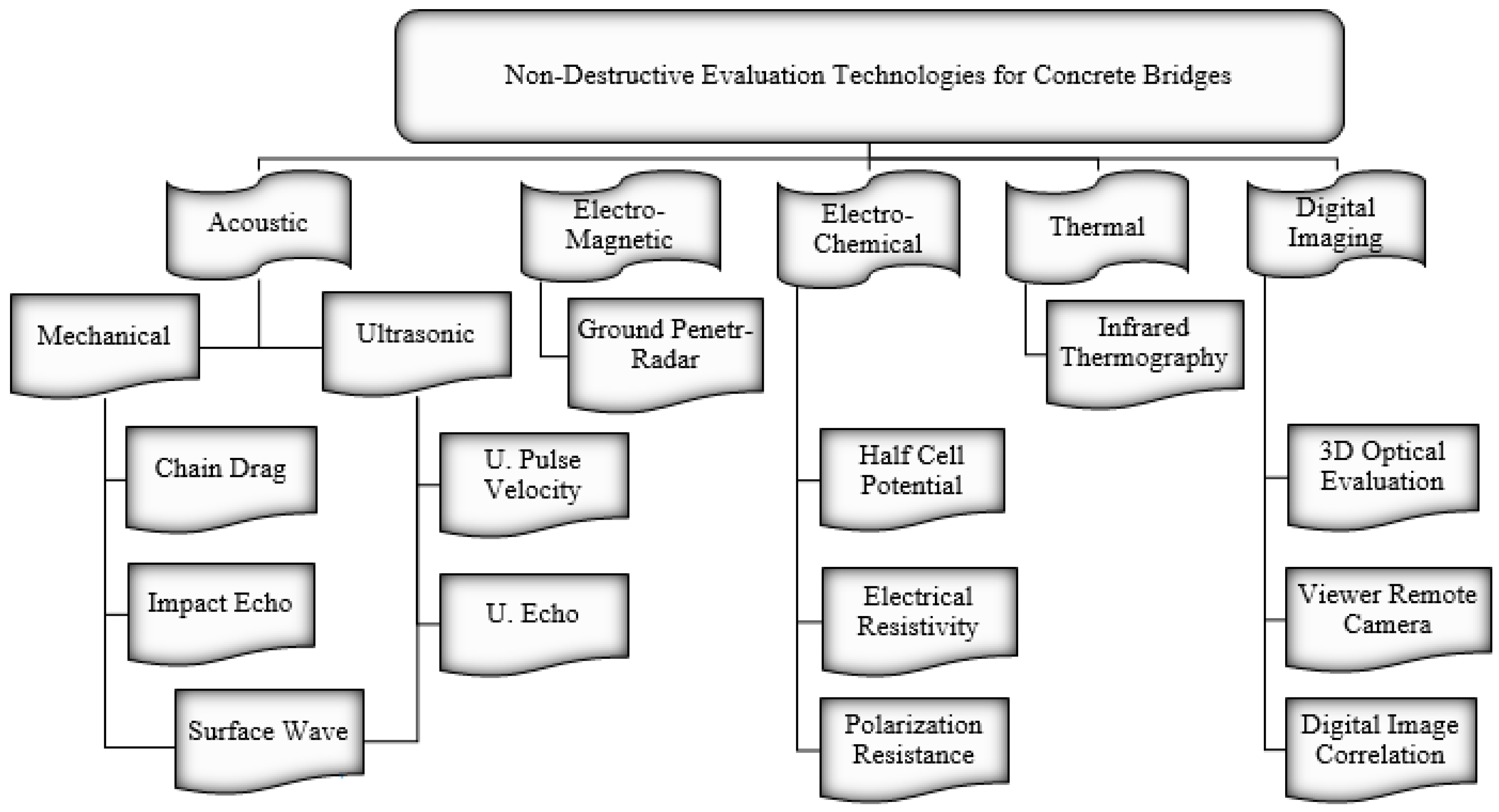
The most commonly used NDE methods in onsite assessment and evaluation of concrete bridge decks are illustrated in Figure 4.
The use of simple NDE tools such as chain drag and hammer sounding is the predominant practice of condition assessment of concrete bridge decks. While having their own merits, such techniques provide information on the deck condition when deterioration has already progressed. They are also unreliable due to access requirements and inherent subjectivity, being unable to identify correctly the repair priorities [62]. These limitations have motivated pursuing advanced NDE techniques for more reliable BCA. For example, probability of active corrosion can be evaluated by half-cell potential [63], electrical resistivity [64], and ground penetrating [65], while the corrosion rate can be identified by the polarization resistance method [66]. The presence of vertical cracks leads to a reduced modulus of elasticity of concrete, which can be captured using the ultrasonic surface wave method [67]. Delamination can be detected using impact echo [68,69], pulse echo [70]; and infrared thermography tests [71,72]. Table 3 compares the advantages and limitations of the most relevant NDT techniques. Further details about their theoretical bases, instrumentations, applications, and data analysis are provided in a variety of sources such as the AASHTO Manual for Bridge Evaluation [34], and a report by the American Concrete Institute, ACI 228.2R, 2013.
5.4.2. NDE Using Remote Sensing Technologies
Remote sensing (RS) is gaining popularity for evaluation of bridge condition. The commonly used RS technologies include 3D-optical bridge evaluation (3DOB), bridge viewer remote camera (BVRC), GigaPan, LIDAR, digital image correlation (DIC), and high-resolution street view-style digital photography [73]. These technologies do not include emplaced sensors such as strain gauges or temperature sensors and can be defined as a form of stand-off SHM and a form of NDE where the device-gathering data are not in contact with the object [74]. Abudayyeh et al. [75] proposed a framework for automated bridge imaging system based on digital image processing. Their models were capable of storing different surface defects in a structured way and generated automated inspection reports. Ahlborn et al. [76] applied different image technologies in assessing the condition of concrete bridge decks and reported that the 3DOB or BVCR techniques based on close range 3D photogrammetry and the GigaPan technique based on street view-style photography are the best technologies for defect measurement for bridge inspections. The DIC technology uses mathematical algorithms to extract displacement information from a series of photographs and can be used to calculate load rating of BCA throughout the service life of the bridge [77]. Hinzen [78] demonstrated the feasibility of damage detection and quantification based on google street view images. However, these technologies should be integrated for complete RC BCA.
5.4.3. NDE Application Approaches
Non-destructive evaluation methods can be applied alone to evaluate certain defects, or can be combined to cover a wider range of testing capabilities in a complementary manner. Although single NDE approaches have their own merits, there is no single NDE technology that is capable of identifying all of the complex deterioration phenomena that can affect a bridge. Many structural problems will be best studied by a particular NDE method, depending upon which physical properties of the construction materials offer the best scheme of reliable defect detection. However, results of BCA from different NDE techniques do not necessarily agree due to the uncertainty associated in data resulting from these techniques [62,79]. Therefore, due to the composite nature of concrete and the many causes of deterioration, a diverse set of NDE technologies could be employed for a more complete conception of a bridge condition. Many case studies exist in which different techniques have been combined. Table 4 illustrates some studies that adopted the NDE combination approach and the objective of these studies. For example, the Federal Highway Administration (FHWA) has recently developed the “RABIT” bridge deck assessment device. RABIT (Robotics Assisted Bridge Inspection Tool) is a fully autonomous robotic system for the condition assessment of concrete bridge decks using the results of multi-model NDE, which utilizes the electrical resistivity, impact echo, ultrasonic surface waves, and ground penetrating radar technologies. The robot’s data visualization platform facilitates an intuitive 3-D presentation of three deterioration types (rebar corrosion, delamination, and concrete degradation) and deck surface features [80]. Pailes [81] developed a multi-NDE BCA model for concrete bridge decks. He identified the correlations between the utilized methods and developed a statistics-based approach to threshold identification for the utilized methods, which were fused and converted into a deterioration based BCA that identifies locations of active corrosion, delamination, and cracking. Results from multi-NDE surveys indicate a high potential to develop more realistic deterioration models for bridges.
5.5. Finite Element Modelling (FEM)
Another tool that is available for BCA is structural modelling. Finite-element modelling (FEM) is a widely used method for the RC BCA. Research has shown that traditional methods of assessing bridge health are conservative in some cases and that a calibrated bridge FEM can provide a more accurate portrayal of bridge response and structural condition. The construction process, erection methods, material properties, geometric accuracy, concrete cracking and creep, and environmental conditions are key factors in the development of robust FE models [91]. For instance, Xia et al. [92] developed a FEM for the quantitative condition assessment of a damaged RC bridge deck, including damage location and extent, residual stiffness evaluation, and load-carrying capacity assessment. The model was validated based on dynamically measured data from the undamaged and damaged decks. The damage location and quantification of the damaged deck were then identified, leading to residual stiffness and load-carrying capacity assessment. Wang et al. [36] developed a FEM to assist the design of load tests and the interpretation of their results. The actual bridge test results, in turn, were used to validate the FE analysis. The measured bridge deflections were found in good agreement with those computed by FE analysis. Alani et al. [93] proposed an integrated bridge health mechanism where a FEM was developed using data from visual inspections and calibrated using NDE survey results.
Bell et al. [48] developed a FEM to calculate the load rating and predict the bridge structural performance which was calibrated via the digital image correlation technique utilized to measure bridge displacements. The system identifies the portion of the bridge which had undergone the greatest amount of deterioration. Ghodoosi et al. [94] evaluated the system reliability of concrete bridges using a FEM and found that the estimated element-level structural conditions degrade faster once corrosion is initiated. FEM can also be used to evaluate the reliability of bridges that use nonconventional materials or structural forms. For example, Ghodoosi et al. [95] developed a FE BCA model for a restrained bridge deck system and calibrated the model with experimental results of static deflection, vibration characteristics, load distribution, and crack patterns. Sousa et al. [91] utilized FEM to assess the long-term performance of prestressed concrete bridges and suggested that data collected using permanently installed monitoring systems is the most reliable strategy to improve such assessments. Subsequently, an integrated framework consisting of both FE modelling and structural monitoring can support management decisions.
6. Bridge Condition Rating Systems
Bridge condition data are generally categorized into condition ratings and condition categories. Condition ratings are codes describing the in-place versus the as-built bridge. Condition categories describe the condition of bridge elements [96]. In the United States, the national bridge inventory (NBI) rating system requires condition ratings for three major bridge structural components: (i) deck; (ii) superstructure; and (iii) substructure using a 0 to 9-point scale (9 being excellent condition and 0 implies absolute failure). The FHWA (1995) classifies deficient bridges into two categories: structurally deficient and functionally obsolete [97]. A bridge is considered structurally deficient if the condition ratings of at least one of its components has a value of 4 or less. The scale of this condition rating system indicates the urgency of an impending loss of structural integrity, but does not consider a detailed inspection of bridge elements, and thus provides little information about the type and location of possible failure. Hence, it is insufficient to formulate repair strategies, or to estimate costs [98].
The bridge sufficiency rating (BSR) system evaluates bridge data by calculating four rating factors. It starts with a value of 100, then deductions are made for bridge deficiencies down to a potential lowest value of 0. The four rating components are comprised of structural adequacy and safety (S1) which has a value of 55%, serviceability and functional obsolescence (S2) accounting for a value of 30%, essentiality for public use (S3) that receives a value of 15%, and finally special reductions (S4) with a value of 13% [97]. Bridge rehabilitation is determined when BSR ≤ 80, whereas eligibility for replacement is indicated by BSR < 50 and structural deficiency or functional obsolescence. The main problem associated with the BSR system is that it is based on NBI condition ratings. To overcome some of the drawbacks of the NBI condition rating, the commonly recognized (CoRe) element condition rating system was developed. It consists of more than one hundred standardized element-level conditions. The ratings of all the elements can be integrated through a weighted aggregation process to compute the overall bridge health index (BHI) that represents the health of the entire bridge structure. The BHI ranges from 0 to 100, where 100 indicates the best state, whereas 0 indicates failure condition. BHI is calculated as the ratio of the sum of the current element value to the sum of the total element value. It can be calculated for an element, a single bridge, or a group of bridges. Although the BHI has been considered by the bridge community as an excellent performance measure, it does not take into consideration inherent uncertainties during the inspection process and its calculation method makes it a deterministic process.
However, to improve the CoRe system of bridge elements, a detailed bridge element inspection system called the AASHTO Guide Manual for Bridge Element Inspection (MBEI) was developed in 2011 [34]. The manual was built on the concept of element-level condition rating and further improvement was implemented in 2013 to include National Bridge Elements (NBEs), Bridge Management Elements (BMEs), and Agency-Developed Elements (ADEs). All elements are assigned a standard number representing one of four condition states: good, fair, poor, and severe. NBEs represent the primary structural components of bridges (decks and slabs, superstructure, substructure, railings, bearings, and culverts) necessary to determine the overall condition and safety of the primary load carrying members. BMEs include components of bridges such as joints, wearing surfaces, protective coating systems and deck/slab protection systems that are typically managed by agencies utilizing BMS. ADEs provide the ability to define custom sub-elements in accordance with the NBEs or BMEs. The new elements contained within the MBEI have been introduced into AASHTOWare™ Bridge Management software BrM, formerly known as Pontis, which is currently the primary bridge management software used by transportation agencies across the USA [99].
In Canada, each Canadian provincial bridge inspection manual has its own condition rating system. For example, in the Ontario Bridge Management System (OBMS), defects are recorded in each of four condition states (i.e., excellent, good, fair, and poor) for each bridge component and performance deficiencies for each component, OSIM [100]. The British Columbia bridge condition index (BCI) is a weighted average of the condition state distribution for various elements where the element replacement cost is used as the weighting factor. The BCI is calculated for various strategies as well as for each budget scenario so that bridge network performance can be compared for different funding levels. Similarly, in Quebec, element, bridge, and network levels are considered where the material condition of a bridge element is assessed based on the severity and extent of the detected defects according to a four-level grading system (i.e., A, B, C, and D). Similar to the condition rating systems developed in the USA, the Canadian bridge condition rating systems do not account for fuzzy information in the evaluation process. Generally, a review of current bridge condition rating systems reveals that they have several drawbacks. For instance, they do not take into consideration subjective information in the assessment process and employ solid linguistic grades that do not account for the gradual transition from one condition category to another. Condition indices obtained from NDE and SHM results can provide more objective and accurate BCA, enabling to monitor the progress of deterioration.
7. Discussion
The process of BCA is challenging, involving the aggregation of diverse distress indicators. Providing a suitable measure and accurate condition evaluation becomes increasingly complex due to uncertainties attributable to inherent subjectivity in the inspection and/or interpretation processes. The advantages and limitations of the commonly used RC BCA approaches are summarized in Table 5. The main tool for evaluating bridge condition is VI, which suffers from limitations such as the required time of inspection, the assessment subjectivity, a number of safety risks associated with field inspections, and the need for a clear line of sight. This could affect the efficiency of decision-making and resource allocation. For instance, VI is effective in identifying external defects such as surface cracks, scaling and spalls, but it cannot detect subsurface flaws such as voids, cracks, delamination, or rebar corrosion.
The RC BCA based on NDE technology can enhance accuracy and yield more efficient condition rating. Simultaneously deploying multiple NDE technologies enables accurate detection and characterization of deterioration and provides a better understanding of bridge conditions. This also makes the assessment of a large population of bridges feasible. However, the practitioner must deal with substantially larger and more complex data, understand how to properly fuse and interpret the data fusion. Automated data collection and analysis using multiple NDE methods integrated into robotic systems can overcome those obstacles. Integrated remote sensing technologies are also gaining popularity as they provide higher evaluation details and more comprehensive defect detection. SHM is becoming common in bridge monitoring. For instance, using wireless SHM to monitor the progression of deficiencies identified during a visual inspection allows for continuous monitoring of identified defects, while maintaining a safe use of the bridge. Yet, SHM systems have some limitations which can hinder their adoption as part of BMSs. These include system complexity which depends on the desired functionality characteristics, system maintenance to sustain long-term operation, and the requirement of automated data analysis to locate potential damages. However, the use of compressed sensing can simultaneously reduce data sampling rates, on-board storage requirements, and communication data payloads. Using traffic-induced vibration response data has several practical advantages:
- It does not interrupt traffic;
- Captures in situ dynamic behaviour of the bridge undergoing in its normal service;
- Can be performed continuously, scheduled periodically, or triggered automatically; and
- Requires no special experimental arrangements. It should be noted that data collected using either NDE methods or SHM systems is the most reliable strategy to improve and update concrete bridge FEM assessment.
7.1. Challenges Requiring Further Research and Development
The present review highlights some tangible findings including:
- The commonly used condition rating systems are qualitative in their definition, subjective in their evaluation, and are generally inadequate as a measure of bridge performance since they still largely depend on visual inspection [80];
- The BHI and Ontario BCI are easy to implement. Yet, their computations make them deterministic condition indices that do not take into account the inherent uncertainty associated with inspection results [101];
- The existing measurement methods for bridge displacement failed to realize long-term and real-time dynamic monitoring of bridge structures, essentially because of their low degree of automation and insufficient precision [52];
- There are discrepancies among the different load rating methods where the reasons for these differences should be addressed [36];
- Although NDE and SHM systems have become the most effective and significant aids for managing bridge infrastructure, there are a limited number of studies that address uncertainty in their measurements based on quantifiable data [102];
- Further work should be undertaken to demonstrate the accuracy of maturing and emerging sensors for use on SHM of bridge structures [103];
- At present, NDE methods, such as impact echo, radar, ultrasonic, resistivity and infrared are being commonly used for quantitative evaluation of bridge condition to augment visual inspection data [58]; and
- Most current research efforts aimed at verifying the capability of integrating NDE techniques to have objective condition assessment systems and determine bridge elements or components condition based on their resilience [81].
- A pre-fire risk assessment strategy should be developed to evaluate the susceptibility of a bridge to fire hazards [29].
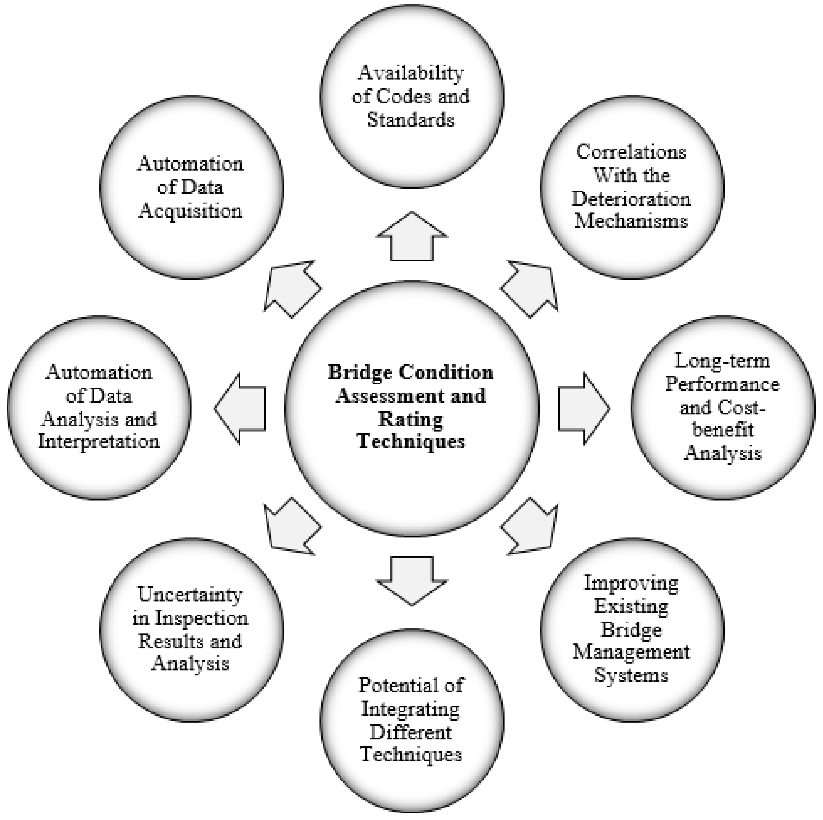
Bridge engineering is rapidly evolving and much work is ongoing in the specific matter of bridge assessment. Figure 5 illustrates the developed conceptual framework to identify challenges that require further concerted research efforts and development. The prospects for improvement was identified as follows:
- Defining solid criteria for the assessment of general bridge condition based on visual inspection;
- Advancing the use of NDE and SHM in mainstream bridge engineering;
- Developing various fully automated data collection systems based on integrated NDE techniques;
- Developing advanced and simplified data analysis and interpretation;
- Integrating of diverse monitoring systems;
- Developing innovative software for integrating SHM/NDE data and aiding in its interpretation;
- Developing correlations between the bridge damage and internal deterioration processes;
- Documenting the cost-benefit of the latest applied techniques and augmenting their future
- Considering the structural robustness and redundancy concepts in the bridge assessment process; and
- Focusing future research studies on most relevant problems. Indeed, fully automated data collection and interpretation analysis are the primary requirements to improve current BMSs.
These will provide rapid and accurate BCA and enable monitoring of deterioration progression through periodical surveys and thus, allow the surveys of hundreds of bridges to become feasible. Consequently, this should yield tremendous reduction in costs associated with the application of NDE technologies and in the frequency and duration of traffic interruptions.
7.2. Selection of Appropriate Condition Assessment Technique
As previously discussed, different deterioration processes lead to different types of bridge component defects, which affect the ability of the evaluation techniques to detect and characterize them. The decision of which technique is more appropriate for BCA is highly dependent on the nature of the available data and is driven by certain factors:
- The mechanism of deterioration in the bridge being investigated;
- Expected output from the evaluation method;
- How the assessment data will be used;
- Level of complexity and available time to conduct the evaluation, and
- The geographic location as well as the traffic density and environmental conditions.
For instance, corrosion can be tracked by monitoring the electrical outputs in a cathodic protection system, whereas scour monitoring involves using acoustic, pier-mounted sensors to track scour depth in the regions of bridge piers and abutments. Cameras are useful for displacement monitoring, whereas strain gauges are suitable for deformations. For bridge decks, if delamination is of greatest concern, impact echo or infrared with a higher degree of automation are appropriate, while radar is suitable if corrosion of greatest concern. Table 6 recommends specific BCA methods for some of the common deterioration mechanisms in different concrete bridge structures.
8. Conclusions
Bridge condition assessment procedures have existed for many decades. It was enlightening to realize the extent of ongoing work that is expanding rapidly considering the staggering resources needed to repair ageing bridges, which often exceed the capabilities of bridge owners. BCA is a scientific and technical procedure aimed at producing evidence of bridge health, assessing its structural reliability, and tailoring procedures to prolong its life. According to this framework, this study has provided a much needed review of recent research accomplishments in this field. The reviewed body of knowledge offers recent advances in VI, LT, NDE, SHM, and FEM techniques. Future research should consider data that drive the decision making of bridge owners from research planning to implementation, with particular focus on added value. Only then can the use of these technologies in mainstream bridge engineering practice truly valuable. Innovative design and construction methodologies should be considered by transportation owners along with upgrading existing BMSs to incorporate recent research. For instance, by verifying the accuracy of a bridge FEM with NDE and SHM results, bridge owners can use analysis output for bridge evaluation and decision making. An understanding of the range of capabilities of different NDE techniques and SHM systems will be helpful in directing bridge stakeholders to evaluate the output and, hence, value can actually be delivered. However, caution is recommended before widely using any such methodology. A method should be used only after careful cost-benefit analysis to determine its value in both the short- and long-term. Lastly, the enormous amount of information and knowledge that has already been produced in the BCA field must be integrated into comprehensive decision making systems, which could be used by various participants in the field for quality management and structural assessment purposes of ageing bridges.
Author Contributions
The first draft of this review paper was developed by T.O. under the supervision of M.L.N. M.L.N. contributed to the conceptualization, editing and enhancement of the initial draft and capturing additional aspects to ensure the comprehensive and far-reaching nature of the review paper and providing insights and further critical discussion and analysis.
Funding
Tarek Omar received a doctoral study scholarship from the Natural Science and Engineering Research Council of Canada (NSERC).
Conflicts of Interest
Both authors have no implicit or explicit conflict of interest of any kind in this study.
References
- Hajializadeh, D.; Obrien, E.; O’Connor, A. Virtual structural health monitoring and remaining life prediction of steel bridges. Can. J. Civ. Eng. 2017, 44, 264–273. [Google Scholar] [CrossRef] [Green Version]
- Jannaty, M.; Eghbalzadeh, A.; Hosseini, S. Using field data to evaluate the complex bridge piers scour methods. Can. J. Civ. Eng. 2016, 43, 218–225. [Google Scholar] [CrossRef]
- Amini, A.; Melville, B.; Ali, T. Local scour at piled bridge piers including an examination of the superposition method. Can. J. Civ. Eng. 2014, 41, 461–471. [Google Scholar] [CrossRef]
- Prendergast, L.; Gavin, K. A review of bridge scour monitoring techniques. J. Rock Mech. Geotech. Eng. 2014, 6, 138–149. [Google Scholar] [CrossRef]
- Saviotti, A. Bridge Assessment, Management & Life Cycle Analysis. J. Mod. Appl. Sci. 2014, 8, 167–183. [Google Scholar]
- Newhook, P.; Edalatmanesh, R. Integrating reliability and structural health monitoring in the fatigue assessment of concrete bridge decks. J. Struct. Infrastruct. Eng. 2013, 9, 619–633. [Google Scholar] [CrossRef]
- Zhang, L.; Zhao, H.; OBrien, E.; Shao, X.; Tan, C. The influence of vehicle–tire contact force area on vehicle–bridge dynamic interaction. Can. J. Civ. Eng. 2016, 43, 769–772. [Google Scholar] [CrossRef]
- Elsaid, A.; Seracino, R. Rapid assessment of foundation scour using the dynamic features of bridge superstructure. J. Constr. Build. Mater. 2014, 50, 42–49. [Google Scholar] [CrossRef]
- Fisher, M.; Chowdhury, N.; Khan, A.; Atamturktur, S. An evaluation of scour measurement devices. J. Flow Meas. Instrum. 2013, 33, 55–67. [Google Scholar] [CrossRef]
- Zarafshan, A.; Iranmanesh, A.; Ansari, F. Vibration-based method and sensor for monitoring of bridge scour. J. Bridge Eng. 2012, 17, 829–838. [Google Scholar] [CrossRef]
- Coe, T.; Brandenberg, J. P-wave Reflection Imaging of a Cast-In-Steel-Shell Bridge Foundation. In Proceedings of the Geo-Frontiers Conference, Dallas, TX, USA, 13–16 March 2011. [Google Scholar]
- Briaud, L.; Hurlebaus, S.; Chang, K.; Yao, C.; Sharma, H.; Yu, O. Real-Time Monitoring of Bridge Scour Using Remote Monitoring Technology; Project; Texas Department of Transportation: Austin, TX, USA, 2011.
- Anderson, N.; Ismael, A.; Thitimakorn, T. Ground-penetrating radar: A tool for monitoring bridge scour. Environ. Eng. Geosci. 2007, 13, 1–10. [Google Scholar] [CrossRef]
- Zanjani, Z.; Patnaik, A. Finite element modeling of the dynamic response of a composite reinforced concrete bridge for structural health monitoring. Intern. J. Adv. Struct. Eng. 2014, 6, 1–14. [Google Scholar] [CrossRef] [Green Version]
- Zhang, W.; Cai, S.; Pan, F.; Zhang, Y. Fatigue life estimation of existing bridges under vehicle and non-stationary hurricane wind. J. Wind Eng. Ind. Aerodyn. 2014, 133, 135–145. [Google Scholar] [CrossRef]
- Zhang, W.; Yuan, H. Corrosion fatigue effects on life estimation of deteriorated bridges under vehicle impacts. J. Eng. Struct. 2014, 71, 128–136. [Google Scholar] [CrossRef]
- Maekawa, K.; Fujiyama, C. Crack Water Interaction and Fatigue Life Assessment of RC Bridge Decks. In Proceedings of the 5th Biot Conference on Poromechanics, Vienna, Austria, 10–12 July 2013; pp. 2280–2289. [Google Scholar]
- Newhook, J.; Gaudet, J.; Edalatmanesh, R. Investigation of an externally restrained concrete bridge deck slab on a multi-girder bridge model. Can. J. Civ. Eng. 2011, 38, 233–241. [Google Scholar] [CrossRef]
- Edalatmanesh, R. Structural Health Monitoring Model for Fatigue Assessment in Concrete Bridge Decks. Ph.D. Thesis, Dalhousie University, Halifax, NS, Canada, 2010; 288p. [Google Scholar]
- Butt, S.; Limaye, V.; Newhook, J. Acoustic survey method to map damage in concrete bridge deck slabs. J. Acoust. Emiss. 2007, 25, 373–378. [Google Scholar]
- Muntasir, A.; Billah, L.; Alam, M. Seismic fragility assessment of highway bridges: A state-of-the-art review. J. Struct. Infrastruct. Eng. 2015, 11, 804–832. [Google Scholar] [CrossRef]
- Attary, N.; Symans, M.; Nagarajaiah, S. Performance Assessment of a Highway Bridge Structure Employing Adaptive Negative Stiffness for Seismic Protection. In Structures Congress 2013: Bridging Your Passion with Your Profession; American Society of Civil Engineers: Reston, VA, USA, 2013; pp. 1736–1746. [Google Scholar]
- Biondini, F.; Frangopol, D. Time effects on robustness and redundancy of deteriorating concrete structures. In Proceedings of the 11th International Conference on Structural Safety and Reliability, New York, NY, USA, 16–20 June 2013; pp. 1–13. [Google Scholar]
- Nogami, Y.; Akiyama, M.; Frangopol, D. Seismic design of RC bridge piers to ensure the post-disaster functionality of road network. In Proceedings of the 11th International Conference on Structural Safety and Reliability, New York, NY, USA, 16–20 June 2013; pp. 3581–3586. [Google Scholar]
- Lau, T.; Waller, L.; Vishnukanthan, K.; Sivathayalan, S. Fragility relationships for probabilistic performance-based seismic risk assessment of bridge inventories. In Proceedings of the Annual Conference-Canadian Society for Civil Engineering, Edmonton, AB, Canada, 6–9 June 2012; Volume 4, pp. 2765–2774. [Google Scholar]
- Taner, Y.; Caner, A. Target damage level assessment for seismic performance evaluation of two-column reinforced concrete bridge bents. J. Bridge Struct. 2012, 8, 135–146. [Google Scholar]
- Ozbulut, E.; Hurlebaus, S. Seismic assessment of bridge structures isolated by a shape memory alloy/rubber-based isolation system. J. Smart Mater. Struct. 2011, 20, 1–12. [Google Scholar] [CrossRef]
- Do Hyung, L.; Joonam, P.; Kihak, L.; Byeong, K. Nonlinear seismic assessment for the post-repair response of RC bridge piers. J. Compos. Part B 2011, 42, 1318–1329. [Google Scholar]
- Naser, M.; Kodur, V. A probabilistic assessment for classification of bridges against fire hazard. J. Fire Saf. 2015, 76, 65–73. [Google Scholar] [CrossRef] [Green Version]
- Garlock, M.; Paya-Zaforteza, I.; Kodur, V.; Gu, L. Fire hazard in bridges: Review, assessment and repair strategies. J. Eng. Struct. 2012, 35, 89–98. [Google Scholar] [CrossRef]
- Akula, M.; Zhang, Y.; Kamat, V.; Lynch, J. Leveraging Structural Health Monitoring for Bridge Condition Assessment. In Proceedings of the Construction Research Congress, Atlanta, GA, USA, 19–21 May 2014; pp. 1159–1168. [Google Scholar]
- Moore, M.; Phares, B.; Graybeal, B.; Rolander, D.; Washer, G. Reliability of Visual Inspection for Highway Bridges; Final Report No. FHWA-RD-01-020; Federal Highway Administration (FHWA): Washington, DC, USA, 2001; Volume 1.
- Agdas, D.; Rice, J.; Martinez, J.; Lasa, I. Comparison of Visual Inspection and SHM as Bridge Condition Assessment Methods. J. Perform. Constr. Facil. 2015, 30, 04015049. [Google Scholar] [CrossRef]
- AASHTO. Manual for Bridge Evaluation, 2nd ed.; AASHTO: Washington, DC, USA, 2011. [Google Scholar]
- Zhang, Q.; Alam, M.; Khan, S.; Jiang, J. performance-based design as per Canadian Highway Bridge Design Code (CHBDC) 2014. Can. J. Civ. Eng. 2016, 43, 741–748. [Google Scholar] [CrossRef]
- Wang, N.; Ellingwood, R.; Zureick, H. Bridge rating using system reliability assessment. II: Improvements to bridge rating practices. J. Bridge Eng. 2011, 16, 863–871. [Google Scholar] [CrossRef]
- Mosavi, A.; Sedarat, H.; O’Connor, M.; Emami, A.; Lynch, J. Calibrating a high-fidelity finite element model of a highway bridge using a multi-variable sensitivity-based optimization approach. J. Struct. Infrastruct. Eng. 2014, 10, 627–642. [Google Scholar] [CrossRef]
- Cruz, J.; Roca, J.; Escusa, G.; Carvalho, J. An alternative system for measuring displacements in bridges by using displacement transducers. In Proceedings of the 3rd conference on Smart Monitoring Assessment and Rehabilitation of Civil Structures, Antalya, Turkey, 7–9 September 2015; pp. 1–13. [Google Scholar]
- Chen, Y.; Feng, M.; Tan, C. Bridge Structural Condition Assessment Based on Vibration and Traffic Monitoring. J. Eng. Mech. 2009, 135, 747–758. [Google Scholar] [CrossRef]
- Alampalli, S. Special Issue on Non-destructive Evaluation and Testing for Bridge Inspection and Evaluation. J. Bridge Eng. 2012, 17, 827–828. [Google Scholar] [CrossRef]
- Wong, K. Design of a structural health monitoring system for long-span bridges. J. Struct. Infrastruct. Eng. 2007, 3, 169–185. [Google Scholar] [CrossRef]
- Feng, D.; Feng, M. Computer vision for SHM of civil infrastructure: From dynamic response measurement to damage detection—A review. J. Eng. Struct. 2018, 156, 105–117. [Google Scholar] [CrossRef]
- Park, K.; Kim, S.; Park, H.; Lee, K. The determination of bridge displacement using measured acceleration. J. Eng. Struct. 2005, 27, 371–378. [Google Scholar] [CrossRef]
- Glisic, B.; Inaudi, D.; Nan, C. Pile monitoring with fiber optic sensors during axial compression, pullout, and flexure tests. J. Transp. Res. Board 2002, 1808, 11–20. [Google Scholar] [CrossRef]
- Palazzo, D.; Friedmann, R.; Nadal, C.; Santos, F.M.; Veiga, L. Dynamic monitoring of structures using a robotic total station. In Proceedings of the Shaping the Change XXIII FIG Congress, Munich, Germany, 8–13 October 2006; pp. 1–10. [Google Scholar]
- Cosser, E.; Roberts, G.; Meng, X.; Dodson, A. The comparison of single frequency and dual frequency GPS for bridge deflection and vibration monitoring. In Proceedings of the 11th International Symposium on Deformation Measurements, Santorini, Greece, 25–28 May 2014; pp. 1–8. [Google Scholar]
- Chan, T.; Ashebo, D.; Tam, H.; Yu, Y.; Chan, T.; Lee, P. Vertical displacement measurements for bridges using optical fiber sensors and CCD cameras: A preliminary study. J. Struct. Health Monit. 2009, 8, 243–249. [Google Scholar] [CrossRef]
- Bell, E.; Peddle, J.; Goudreau, A. Bridge Condition Assessment using Digital Image Correlation and Structural Modeling. In Proceedings of the 6th International IABMAS Conference, Stresa, Lake Maggiore, Italy, 8–12 July 2012; pp. 330–338. [Google Scholar]
- Guan, S.; Rice, J.; Li, C.; Wang, G. Bridge deflection monitoring using small, low-cost radar sensors. In Proceedings of the Structures Congress, ASCE, Boston, MA, USA, 3–5 April 2014; pp. 2853–2862. [Google Scholar]
- Raghavan, A.; Cesnik, C.E. Review of guided-wave structural health monitoring. Shock Vib. Digest J. 2007, 39, 91–116. [Google Scholar] [CrossRef]
- Gordon, S.J.; Lichti, D.D. Modeling Terrestrial Laser Scanner Data for Precise Structural Deformation Measurement. J. Surv. Eng. 2007, 133, 72–80. [Google Scholar] [CrossRef]
- Zhao, X.; Liu, H.; Yu, Y.; Xu, X.; Hu, W.; Li, M.; Ou, J. Bridge Displacement Monitoring Method Based on Laser Projection-Sensing Technology. J. Sens. 2015, 15, 8444–8463. [Google Scholar] [CrossRef] [PubMed] [Green Version]
- Bao, Y.; Li, H.; Sun, X.; Yu, Y.; Ou, J. Compressive sampling–based data loss recovery for wireless sensor networks used in civil SHM. J. Struct. Health Monit. 2013, 12, 78–95. [Google Scholar] [CrossRef]
- Higuera, M.; Rodriguez, L.; Quintela, A.; Cobo, A. Fiber optic sensors in structural health monitoring. J. Light Wave Technol. 2011, 29, 587–608. [Google Scholar] [CrossRef]
- O’Connor, S.; Lynch, J.; Gilbert, A. Compressed sensing embedded in an operational wireless sensor network to achieve energy efficiency in monitoring applications. J. Smart Mater. Struct. 2012, 23, 1–17. [Google Scholar] [CrossRef]
- Olsen, J.; Chen, Z.; Hutchinson, T.; Kuester, F. Optical Techniques for Multiscale Damage Assessment. J. Geomat. Nat. Hazards Risk 2013, 4, 49–70. [Google Scholar] [CrossRef]
- Guldur, B.; Yan, Y.; Hajjar, J. Condition Assessment of Bridges Using Terrestrial Laser Scanners. In Proceedings of the Structures Congress, Portland, OR, USA, 23–25 April 2015; pp. 355–367. [Google Scholar]
- Laory, I.; Hadj, N.; Trinh, T.; Smith, I. Measurement System Configuration for Damage Identification of Continuously Monitored Structures. J. Bridge Eng. 2012, 17, 857–866. [Google Scholar] [CrossRef] [Green Version]
- Huntley, S.A.; Valsangkar, A.J. Behaviour of H-piles supporting an integral abutment bridge. Can. Geotech. J. 2014, 51, 713–734. [Google Scholar] [CrossRef]
- Hu, X.; Wang, B. A Wireless Sensor Network-Based Structural Health Monitoring System for Highway Bridges. J. Comput. Aided Civ. Infrastruct. Eng. 2013, 28, 193–209. [Google Scholar] [CrossRef]
- Gucunski, N.; Imani, A.; Romero, F.; Nazarian, S.; Yuan, D.; Wiggenhauser, H. Non-destructive testing to identify concrete bridge deck deterioration. In Proceedings of the 92nd Meet, TRB, Washington, DC, USA, 13–17 January 2013. SHRP 2 Report. [Google Scholar]
- Yehia, S.; Abudayyeh, O.; Nabulsi, S.; Abdel-Qader, I. Detection of Common Defects in Concrete Bridge Decks Using NDE Techniques. J. Bridge Eng. 2007, 12, 215–225. [Google Scholar] [CrossRef]
- Pradhan, B.; Bhattacharjee, B. Half-Cell Potential as an Indicator of Chloride-Induced Rebar Corrosion Initiation in RC. J. Mater. Civ. Eng. 2009, 21, 543–552. [Google Scholar] [CrossRef]
- Brown, D. Mechanisms of corrosion of steel in concrete in relation to design, inspection, and repair of offshore and coastal structures. ACI Spec. Publ. 1980, 65, 169–204. [Google Scholar]
- Varnavina, A.; Khamzin, A.; Torgashov, E.; Sneed, L.; Goodwin, B.; Anderson, N. Data acquisition and processing parameters for concrete bridge deck condition assessment using ground-coupled ground penetrating radar. J. Appl. Geophys. 2015, 114, 123–133. [Google Scholar] [CrossRef]
- Cady, P.D.; Gannon, E.J. Condition Evaluation of Concrete Bridges Relative to Reinforcement Corrosion. Volume 8: Procedure Manual; SHRP-S/FR-92-110; NRC: Washington, DC, USA, 1992; 124p. [Google Scholar]
- Nazarian, S.; Baker, R.; Crain, K. Development and Testing of a Seismic Pavement Analyzer; Report SHRP-H-375, Strategic Highway Research Program; NRC: Washington, DC, USA, 1993; 169p. [Google Scholar]
- Kee, S.; Oh, T.; Popovics, J.; Arndt, R.; Zhu, J. Nondestructive Bridge Deck Testing with Air-Coupled Impact-Echo and Infrared Thermography. J. Bridge Eng. 2012, 17, 928–939. [Google Scholar] [CrossRef]
- Parisa, S.; Julia, W.; Herbert, W. Detection of Delamination in Concrete Bridge Decks by Joint Amplitude and Phase Analysis of USA Measurements. J. Bridge Eng. 2013, 19, 1–11. [Google Scholar]
- Krause, M.; Mayer, K.; Friese, M.; Milmann, B.; Mielentz, F.; Ballier, G. Progress in ultrasonic tendon ducts imaging. In Proceedings of the 7th International Symposium NDT in Civil Engineering (NDTCE 09), Nantes, France, 30 June–3 July 2009; pp. 147–154. [Google Scholar]
- Washer, G.; Fenwick, R.; Bolleni, N.; Harper, J. Effects of environmental variable on infrared imaging subsurface features of concrete bridges. J. Transp. Res. Record 2009, 2108, 107–114. [Google Scholar] [CrossRef]
- Seong, K.; Taekeum, O.; Popovics, S.; Arndt, W.; Zhu, J. Non-destructive Bridge Deck Testing with Air-Coupled IE and IR Thermography. J. Bridge Eng. 2012, 17, 928–939. [Google Scholar]
- Adhikari, S.; Moselhi, O.; Bagchi, A. Automated Prediction of Condition State Rating in Bridge Inspection. J. Gerontechnol. 2012, 11, 81–88. [Google Scholar]
- Vaghefi, K.; Oats, R.; Harris, D.; Ahlborn, T.; Brooks, C. Evaluation of Commercially Available Remote Sensors for Highway Bridge Condition Assessment. J. Bridge Eng. 2012, 17, 886–895. [Google Scholar] [CrossRef] [Green Version]
- Abudayyeh, O.; Al-Bataineh, M.; Abdel-Qader, I. An Imaging Data Model for Concrete Bridge Inspection. J. Adv. Eng. Softw. 2004, 35, 473–480. [Google Scholar] [CrossRef]
- Ahlborn, M.; Vaghefi, K.; Harris, D.; Brooks, C. Measurement and communication of bridge performance with remote sensing technologies. J. Transp. Res. Rec. 2012, 2292, 141–149. [Google Scholar] [CrossRef]
- Sanayei, M.; Phelps, J.; Sipple, J.; Bell, E.; Brenner, B. Instrumentation NDT & FEM Updating for Bridge Evaluation Using Strain measurements. J. Bridge Eng. 2012, 17, 130–138. [Google Scholar]
- Hinzen, G. Support of Macroseismic Documentation by Data from Google Street View. J. Seismol. Res. Lett. 2013, 84, 982–990. [Google Scholar] [CrossRef]
- Huston, D.; Cui, J.; Burns, D.; Hurley, D. Concrete bridge deck condition assessment with automated multi-sensor techniques. J. Struct. Infrastruct. Eng. 2011, 7, 1–11. [Google Scholar]
- Gucunski, N.; Kee, S.; La, H.; Basily, B.; Maher, A.; Ghasemi, H. Implementation of a Fully Autonomous Platform for Assessment of Concrete Bridge Decks RABIT. In Proceedings of the Structures Congress, Portland, OR, USA, 23–25 April 2015; pp. 367–378. [Google Scholar]
- Pailes, B. Damage Identification, Progression, and Condition Rating of Bridge Decks Using Multi-Modal Non-Destructive Testing. Ph.D. Thesis, Rutgers, The State University of New Jersey, New Brunswick, NJ, USA, 2014; 184p. [Google Scholar]
- Alt, D.; Meggers, D. Determination of Bridge Deck Subsurface Anomalies Using Infrared Thermography and Ground Penetrating Radar; Report FHWA-KS-96-2; Kansas Department of Transportation: Topeka, KS, USA, 1996; 18p.
- Barnes, C.; Trottier, J. Ground-penetrating radar for network-level concrete deck repair management. J. Transp. Eng. 2000, 126, 257–262. [Google Scholar] [CrossRef]
- Scott, M.; Rezaizadeh, A.; Delahaza, A.; Santos, G.; Moore, M. A comparison of NDE methods for bridge deck assessment. J. NDT E Int. 2003, 36, 245–255. [Google Scholar] [CrossRef]
- Clark, M.R.; McCann, D.M.; Forde, M.C. Application of infrared thermography to the non-destructive testing concrete and masonry bridges. J. NDT E Int. 2003, 36, 265–275. [Google Scholar] [CrossRef]
- Zheng, Y.H.; Ng, K.E. Evaluation of concrete structures by advances non-destructive test methods-impact echo, impulse response test and radar survey. In Proceedings of the NDT-CE Conference, Berlin, Germany, 16–19 September 2003. [Google Scholar]
- Wood, J.C.; Rens, K.L. Non-destructive testing of the Lawrence Street Bridge. In Proceedings of the Structures Congress: Structural Engineering and Public Safety, St. Louis, MI, USA, 18–21 May 2006; Cross, B., Finke, J., Eds.; ASCE: Reston, VA, USA, 2006; pp. 1–15. [Google Scholar]
- Algernon, D.; Hiltunen, R.; Ferraro, C.; Ishee, C. Rebar detection with cover meter and ultrasonic pulse echo combined with automated scanning system. J. Transp. Res. Rec. 2011, 2251, 123–131. [Google Scholar] [CrossRef]
- Arndt, R.; Jalinoos, F.; Cui, J.; Huston, D. Periodic NDE for bridge maintenance. In Proceedings of the Structural Faults and Repair Conference, Edinburgh, UK, 15–17 June 2010. [Google Scholar]
- Oh, T.; Kee, S.; Arndt, R.; Popovics, J.S.; Zhu, J. Comparison of NDT methods for assessment of a concrete bridge deck. J. Eng. Mech. 2013, 139, 305–314. [Google Scholar] [CrossRef]
- Sousa, H.; Bento, J.; Figueiras, J. Assessment and Management of Concrete Bridges Supported by Monitoring Data-Based Finite-Element Modeling. J. Bridge Eng. 2014, 19, 1–12. [Google Scholar] [CrossRef]
- Xia, P.; Brownjohn, J. Bridge Structural Condition Assessment Using Systematically Validated Finite-Element Model. J. Bridge Eng. 2005, 9, 418–423. [Google Scholar] [CrossRef]
- Alani, A.; Aboutalebi, M.; Kilic, G. Integrated health assessment strategy using NDT for reinforced concrete bridges. J. NDT E Int. 2013, 61, 80–94. [Google Scholar] [CrossRef]
- Ghodoosi, F.; Bagchi, A.; Zayed, T. System-Level Deterioration Model for Reinforced Concrete Bridge Decks. J. Bridge Eng. 2015, 20, 1–10. [Google Scholar] [CrossRef]
- Ghodoosi, F.; Bagchi, A.; Zayed, T. Reliability-Based Condition Assessment of an Externally Restrained Bridge Deck Considering Uncertainties in Key Design Parameters. J. Perform. Constr. Facil. 2014, 30, 04014189. [Google Scholar] [CrossRef]
- Nasrollahi, M.; Washer, G. Estimating Inspection Intervals for Bridges Based on Statistical Analysis of National Bridge Inventory Data. J. Bridge Eng. 2014, 11, 1–11. [Google Scholar] [CrossRef]
- FHWA. Recording and Coding Guide for the Structure Inventory and Appraisal of the Nation’s Bridges; FHWA-PD-96-001; Federal Highway Administration, U.S. Department of Transportation: Washington, DC, USA, 1995.
- Bektas, B.; Carriquiry, A.; Smadi, O. Using Classification Trees for Predicting National Bridge Inventory Condition Ratings. J. Infrastruct. Syst. 2013, 19, 425–433. [Google Scholar] [CrossRef]
- Reardon, M.F.; Chase, S. Migration of Element-Level Inspection Data for Bridge Management System. In Proceedings of the TRB, 95th Annual Meeting, Washington, DC, USA, 10–14 January 2016; pp. 1–15. [Google Scholar]
- Ontario Structure Inspection Manual-OSIM; Ontario Ministry of Transportation: St. Catharines, ON, Canada, 2008; 394p.
- Dinh, K.; Zayed, T.; Romero, F.; Tarussov, A. Method for Analyzing Time-Series GPR Data of Concrete Bridge Decks. J. Bridge Eng. 2015, 20, 1–8. [Google Scholar] [CrossRef]
- Hesse, A.; Atadero, R.; Ozbek, M. Uncertainty in Common NDE Techniques for Use in Risk-Based Bridge Inspection Planning: Existing Data. J. Bridge Eng. 2015, 20, 1–8. [Google Scholar] [CrossRef]
- Webb, G.; Vardanega, P.; Middleton, C. Categories of SHM deployments: Technologies and capabilities. J. Bridge Eng. 2015, 20, 04014118. [Google Scholar] [CrossRef]
Figure 1.
Basic components of a bridge management system (BMS).

Figure 2.
Methodological framework for literature review of reinforced concrete (RC) bridge condition assessment.
Figure 2.
Methodological framework for literature review of reinforced concrete (RC) bridge condition assessment.

Figure 3.
Condition assessment mechanisms of reinforced concrete bridges.

Figure 4.
Condition assessment mechanisms of reinforced concrete bridges.

Figure 5.
Conceptual framework to identify challenges that require further research in bridge condition assessment.
Figure 5.
Conceptual framework to identify challenges that require further research in bridge condition assessment.


Table 1.
Evaluation techniques for RC bridge performance indicators and the related references.
| Performance Indicator | Evaluation Technique | Reference | Year |
|---|---|---|---|
| Scour Assessment | Bridge Dynamic Response (BDR) | [8] | 2014 |
| Sound Wave Devices (SWD) | [9] | 2013 | |
| Driven Rod Device and Strain-Sensor (DRD) | [10] | 2012 | |
| Fibre-Optic Bragg Grating Sensors (FBG) | [10] | 2012 | |
| Ultrasonic P-Wave Reflection Imaging (URI) | [11] | 2011 | |
| Single-Use Devices (SUD) | [12] | 2011 | |
| Ground Penetrating Radar (GPR) | [13] | 2007 | |
| Electrical Conductivity Devices (ECD) | [13] | 2007 | |
| Fatigue and Fracture Assessment | Bridge Dynamic Response Using FEM (BDR) | [14] | 2014 |
| Vehicle-Bridge-Wind Dynamic System (VWDS) | [15] | 2014 | |
| Corrosion-Fatigue Strength Reduction (CFSR) | [16] | 2014 | |
| Integrating Reliability and SHM (IR-SHM) | [6] | 2013 | |
| Crack Water Interaction (CWI) | [17] | 2013 | |
| Static Ultimate Testing (SUT) | [18] | 2011 | |
| Fatigue Damage Accumulation (FDA) | [19] | 2010 | |
| Acoustic Survey-Crack Monitoring (AS-CM) | [20] | 2007 | |
| Seismic Assessment | Seismic Fragility Analysis (SFA) | [21] | 2015 |
| Negative Stiffness Devices (NSD) | [22] | 2013 | |
| Probabilistic Static Analyses (PSA) | [23] | 2013 | |
| Seismic Design of RC Bridges | [24] | 2013 | |
| Probabilistic Performance Analysis (PPA) | [25] | 2012 | |
| Target Damage Level (TDL) | [26] | 2011 | |
| Rubber-Based Isolation System (RIS) | [27] | 2011 | |
| Post Repair Response (PRR) | [28] | 2010 |
Table 2.
Summary of common structural health monitoring systems of RC bridges.
| Monitoring System | Advantages and Limitations |
|---|---|
| Displacement Sensors [43] |
|
| Acceleration Sensors [43] |
|
| Strain Sensors [44] |
|
| Robotic Total Station [45] |
|
| GPS Satellite-Surveying [46] |
|
| Motion Detection Cameras [47] |
|
| Digital Image Cross-Correlation [48] |
|
| Radar Sensors [49] |
|
| Laser Doppler Vibrometer [50] |
|
| Terrestrial Laser Scan [51] |
|
| Laser Projection Sensing [52] |
|
Table 3.
Summary of common structural health monitoring systems of RC bridges.
| Technique | Physical Phenomena | Applications | Advantages and Limitations |
|---|---|---|---|
| Impact Echo (IE) |
|
|
|
| Ultrasonic Pulse Echo (UPE) |
|
|
|
| Half-Cell Potential (HCP) |
|
|
|
| Ground Penetrating Radar (GPR) |
|
|
|
| Infrared Thermography (IRT) |
|
|
|
Table 4.
Studies utilized combined non-destructive evaluation (NDE) techniques approach to evaluate RC bridges.
Table 4.
Studies utilized combined non-destructive evaluation (NDE) techniques approach to evaluate RC bridges.
| Techniques Utilized | Objective of the Study | Reference | Year |
|---|---|---|---|
| Infrared, Radar | Delamination Detection | [82] | 1996 |
| Radar, Chain Drag, Half-Cell Potential | Damage Detection | [83] | 2000 |
| Impact Echo, Radar, Chain Drag | Comparative Study | [84] | 2003 |
| Infrared, Chain Drag | Delamination Detection | [85] | 2003 |
| Radar, Impact Echo, Dynamic Response | Damage Detection | [86] | 2003 |
| Radar, Ultrasonic Echo, Hammer Sounding | Comparative Study | [87] | 2006 |
| Impact Echo, Radar, Infrared | Comparative Study | [62] | 2007 |
| Impact Echo, Ultrasonic Echo | Measuring Thickness | [88] | 2011 |
| Ultrasonic Echo, Radar, Infrared, Half-Cell Potential | Comparative Study | [89] | 2010 |
| Impact Echo, Radar, Half-Cell, Ultrasonic Surface Waves, Electrical Resistivity, Infrared, Pulse Echo, Impulse Response | Comparative Study | [61] | 2013 |
| Impact Echo, Infrared, Chain Drag | Damage Detection | [90] | 2013 |
Table 5.
Comparison of condition assessment techniques for RC bridges.
| Technique | Description, Advantages and Limitations |
|---|---|
| Visual Inspection (VI) | Description: trained engineers recognize, register, and evaluate the physical condition of different bridge elements using inspection manuals and defined codes. The primary and most common interval for inspections is 24 months. Advantages: the most significant aid for bridge condition evaluation. BMSs rely primarily on VI to record bridge component condition ratings, which are quantified and standardized through a priority-ranking procedure. Limitations: subjective evaluation; results greatly depend on the qualifications of those conducting inspections; the findings may not be identical. Consider only the observed physical health of the bridge and cannot detect hidden defects. |
| Load Testing Response (LTR) | Description: determine the live-load carrying capacity of an existing bridge by measuring the actual load the bridge can carry without distress. Condition ratings can be determined by allowable stress, load factor, or load and resistance factor methods. Advantages: safe conservative analysis methods. The governing rating is the lesser of the shear capacity of the critical bridge component. Development and updating the load rating software is undertaken by AASHTO. Limitations: costly and time consuming. The three rating methods may lead to differently rated capacities and posting limits for the same bridge. No guidance as to which method should be used for specific circumstances. |
| Structure Health Monitoring (SHM) | Description: encompasses a range of methods and practices designed to capture structural response, detect anomalous behaviour, and to assess the bridge condition based on a combination of measurement, modelling and analysis. Advantages: reliable and potentially real-time bridge assessment. More meaningful than using load response data. Can be deployed for short-term and long-term assessment. Appropriate for movable bridges than any other method. Limitations: wireless sensors rely on battery power. The size and complexity of the bridge being monitored could result in complex systems. SHM systems often create liability issues. Require routine, on-site maintenance to sustain long-term operation. |
| Non-Destructive Evaluation (NDE) | Description: a number of techniques introduced exploit various physical phenomena (acoustic, seismic, electric, electromagnetic, and thermal, etc.) to detect and characterize deterioration processes without damaging the elements. Advantages: provide effective, and accurate condition assessment. Objectify the inspection process and make it faster and more reliable. Integration of different techniques is the best approach to identify several different damage states. Limitations: applying only one technology provides limited information about the bridge condition. No single technology is capable of identifying all of the various deterioration phenomena. Require trained personnel for data collection and analysis. |
| Finite Element Modelling (FEM) | Description: numerical analysis to investigate the behaviour and response of a bridge structural system. Usually calibrated using results of field inspection supported by NDE technologies or by static or dynamic tests on the structure. Advantages: allows detailed visualization, can be created using data from visual inspection and then parameterised and calibrated using information from NDE and SHM results. A FEM is able to satisfactorily capture short-term performance (e.g., load tests). Limitations: FE models typically require calibration. Long-term assessment is a challenge due to advances in structural materials and construction methods. |
Table 6.
Appropriate investigation methods for some deterioration mechanisms in RC bridges.
| Concerned Assessment | Investigation Method |
|---|---|
| Map patterns of distress such as surface cracks, spalling, scaling, and erosion | Integrated visual inspection and remote sensing technologies. |
| Scour damage | Vibration based techniques, scour sensors. |
| Fatigue damage | Acoustic emission techniques (stress waves). |
| Potential of corrosion | Half-Cell Potential, electrical resistivity |
| Delamination and cracks detection | Air-coupled impact-echo and infrared thermography. |
| Corrosion detection in prestressing strands (in adjacent concrete box-beam bridges) | Magnetic techniques (using magnetic reluctance meters). |
| Damages in long-span suspension bridges | Health monitoring techniques (using strain sensors) and FEM. |
| Initial yield in posttensioned concrete beams | Acoustic emission techniques (stress waves). |
| Subsurface defects in superstructure components | Remote sensing and health monitoring technologies. |
| Unknown foundation depth, integrity and type. | Parallel seismic and ultra-seismic techniques. |
© 2018 by the authors. Licensee MDPI, Basel, Switzerland. This article is an open access article distributed under the terms and conditions of the Creative Commons Attribution (CC BY) license (http://creativecommons.org/licenses/by/4.0/).
Share and Cite
MDPI and ACS Style
Omar, T.; Nehdi, M.L. Condition Assessment of Reinforced Concrete Bridges: Current Practice and Research Challenges. Infrastructures 2018, 3, 36. https://0-doi-org.brum.beds.ac.uk/10.3390/infrastructures3030036
AMA Style
Omar T, Nehdi ML. Condition Assessment of Reinforced Concrete Bridges: Current Practice and Research Challenges. Infrastructures. 2018; 3(3):36. https://0-doi-org.brum.beds.ac.uk/10.3390/infrastructures3030036
Chicago/Turabian StyleOmar, Tarek, and Moncef L. Nehdi. 2018. "Condition Assessment of Reinforced Concrete Bridges: Current Practice and Research Challenges" Infrastructures 3, no. 3: 36. https://0-doi-org.brum.beds.ac.uk/10.3390/infrastructures3030036