Behavior of Geogrid-Reinforced Portland Cement Concrete under Static Flexural Loading


Department of Civil Engineering, Widener University, Chester, PA 19803, USA
*
Author to whom correspondence should be addressed.
Infrastructures 2018, 3(4), 41; https://0-doi-org.brum.beds.ac.uk/10.3390/infrastructures3040041
Submission received: 8 August 2018
/
Revised: 17 September 2018
/
Accepted: 24 September 2018
/
Published: 26 September 2018
Abstract
:Geogrids have been investigated by a limited number of studies as a potential alternative to steel reinforcement for Portland cement concrete (PCC), especially in situations where using steel reinforcement may not be suitable due to constructability and durability limitations. This study aims to investigate the flexural behavior of simply-supported concrete beams reinforced by geogrids, which would aid in assessing the potential use of geogrids for concrete structures such as overlays and other thin sections. Another objective of this study is to examine the potential benefits of embedding geogrids in PCC, and to investigate the mechanism and effectiveness of geogrid reinforcement in PCC. Plain and geogrid-reinforced concrete beams were fabricated and tested under a static four-point flexural bending load. The midspan deflection and crack mouth opening displacement (CMOD) of the beams were recorded during loading. Additionally, for geogrid-reinforced beams, strain gages were attached on the geogrids to monitor the strains that developed in geogrids. Results reveal that the geogrid primarily contributes to improving the ductility of the post-peak behavior of plain concrete and to delaying the collapse failure of concrete beams. Strain measurements of the geogrids indicate that the geogrids were activated and mobilized instantly upon the application of the flexural load. Both the strain measurements and observations of the geogrids post failure suggest that there was no slippage between the geogrids and the concrete.
1. Introduction
Although steel reinforcing bars (rebars) are the most commonly-used reinforcements for Portland cement concrete (PCC), there are scenarios where steel rebars are not suitable for reinforcing PCC due to constructability and durability limitations. For example, steel rebars are difficult place in thin sections, such as concrete overlays, white-toppings, and some thin architectural elements. Additionally, steel rebars are prone to corrosion in thin sections due to insufficient concrete cover [1]. Other materials have been investigated for their use in PCC as alternatives to steel rebars, including fiber reinforced plastic polymer (FRP) bars, tendons, and FRP grids [2,3,4,5]. Particularly, a great deal of effort has gone into investigating discrete fibers for reinforcing PCC, where fibers are found to mainly enhance post-cracking performance of PCC such as toughness and control of cracking [6,7,8,9,10].
A limited number of studies have proposed and investigated the innovative use of a traditional material, geogrids, for reinforcing PCC. Geogrids are two-dimensional planar polymeric structures that consists of a mesh-like network of connected tensile elements, called ribs. The ribs are linked by extrusion, bonding, or interlacing, and have openings or apertures that are usually larger than the ribs. Depending on the aperture shape and rib direction, there are three primary types of geogrids: uniaxial, biaxial, and triaxial. Geogrids are usually embedded in unbound geomaterials with which they interact through interlocking and shear resistance to provide reinforcement to earthen structures such as earth retaining walls, slopes, embankments, shallow foundations, and pavements [11,12,13]. Due to their relatively high strength-to-weight ratio, ease of handling, and relatively lower cost, geogrids have been increasingly investigated for potential use as reinforcements for PCC.
Studies by Tang et al. in 2008 [14] and El Meski and Chehab in 2014 [15] investigated the potential benefits of geogrids for flexural capacity and strength of concrete beams. It was found that geogrids can provide post-cracking ductility and an increase in load capacity, depending upon the type of geogrid being used. Another study based on laboratory experiments and numerical modeling examined the use of geogrids for concrete thin overlays, and found that geogrids provide significant improvements to concrete overlay performance in the post-cracking regime in terms of strength, ductility, and mode of failure [16]. A laboratory study conducted on 900 mm × 900 mm × 60 mm concrete slabs reinforced by geogrids found that geogrids can improve the flexural performance and cracking resistance of concrete slabs after examining the ductility, fracture energy, and formation of cracks in the specimens [17]. Geogrids have also been investigated for use as confinement in reinforced concrete; it was found that the proper application of geogrids with steel fiber reinforced concrete can help achieve ductile behavior and alter the brittle mode of failure [18,19]. In addition to influencing the mechanical properties and behavior of PCC, geogrids were found to reduce the drying shrinkage of concrete by about 20% in 75 mm × 75 mm × 280 mm concrete prism specimens, and about 15% in 280 mm × 280 mm × 30 mm concrete slabs [20].
Contrary to unbound granular geomaterials in earthen structures, PCC is a material bonded by cement. As a result, the reinforcing mechanism of geogrids embedded in PCC are expected to be different than that when geogrids are embedded in earthen structures. The reinforcing mechanisms and effectiveness of geogrids for unbound granular geomaterials have been well studied and examined [21,22]. However, the effectiveness of a geogrid in reinforcing PCC is not well understood, despite the benefits evidenced by findings from the aforementioned studies. It is unclear how much the geogrid is engaged and mobilized under flexural loading, thus contributing to the effectiveness of the geogrid in reinforcing PCC. Furthermore, it is of interest to know whether geogrids are activated prior to the commencement of concrete cracking or failure. Using strain gages to monitoring strains developed in geogrids during loading enables a close examination of the effectiveness of geogrids in reinforcing PCC, and the way in which geogrids respond to loading when embedded in PCC.
The objective of this study is twofold: (1) to investigate the flexural behavior of simply-supported geogrid-reinforced PCC beams under a static four-point bending load, which would aid in assessing the use of geogrid reinforcement in concrete structures such as overlays and other thin concrete sections; and (2) to examine the benefits of embedding geogrids in PCC, and investigate the mechanism and effectiveness of geogrid reinforcement therein. A triaxial geogrid is used in this study to reinforce plain concrete of normal strength. Four-point bending tests on simply-supported beams were conducted for both unreinforced plain concrete and geogrid-reinforced concrete. Load and midspan deflection data were recorded during the four-point bending tests. Additionally, for reinforced concrete beams, the geogrids were instrumented with strain gages at various locations to monitor the strains developed in the geogrids during the flexural loading.
2. Experimental Program
2.1. Materials
All concrete beams used the same concrete mixtures, consisting of Type I Portland cement, fine aggregates of natural sand, and coarse crushed limestone. The water/cement ratio of the mixtures is 0.456. The concrete mixture design has a 28-day compressive strength of 31 MPa per ASTM C 39, representing a normal strength Portland cement concrete (PCC). Table 1 shows the mix design used for all the concrete beam specimens. The nominal maximum size of the coarse aggregates is 12.5 mm, which is smaller than the opening apertures of the geogrids, and allows the coarse aggregates to pass through the apertures and avoid blocking the geogrid.
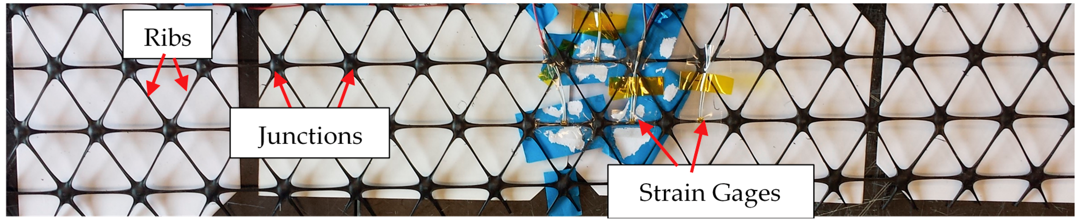
The geogrid used in this study is triaxial with 40 mm × 40 mm × 40 mm triangular apertures, as shown in Figure 1. The proportion of the geogrid aperture opening size and the nominal maximum aggregate size allow for interlocking between the geogrid and several large aggregates, thus leading to a better interaction between the geogrid and the concrete. The geogrid is made by punching and drawing polypropylene (PP) sheets in three equilateral directions. The basic structural elements of a geogrid consist of ribs and junctions, as shown in Figure 1. Table 2 presents the index and mechanical properties of the geogrid provided by the manufacturer. Although the tensile strength of the geogrid reinforcement is of interest for a better understanding of the reinforcing effectiveness, the tensile strength of the triaxial geogrid is unavailable at this point, likely due to the complexity in testing triangular planar geometries and the lack of a testing standard for triaxial geogrids. When subjected to chemically aggressive environments based on the EPA 9090 test method [23], the geogrid also has a 100% resistance to chemical degradation, i.e., a strong resistance to loss of load capacity or structural integrity [24]. This suggests that the durability of the geogrid is adequate to resist the harsh environment due to chemical reactions during concrete curing. The geogrids were cut into 152 mm (width) × 762 mm (length) to fit into the concrete steel mold.
2.2. Specimen Fabrication
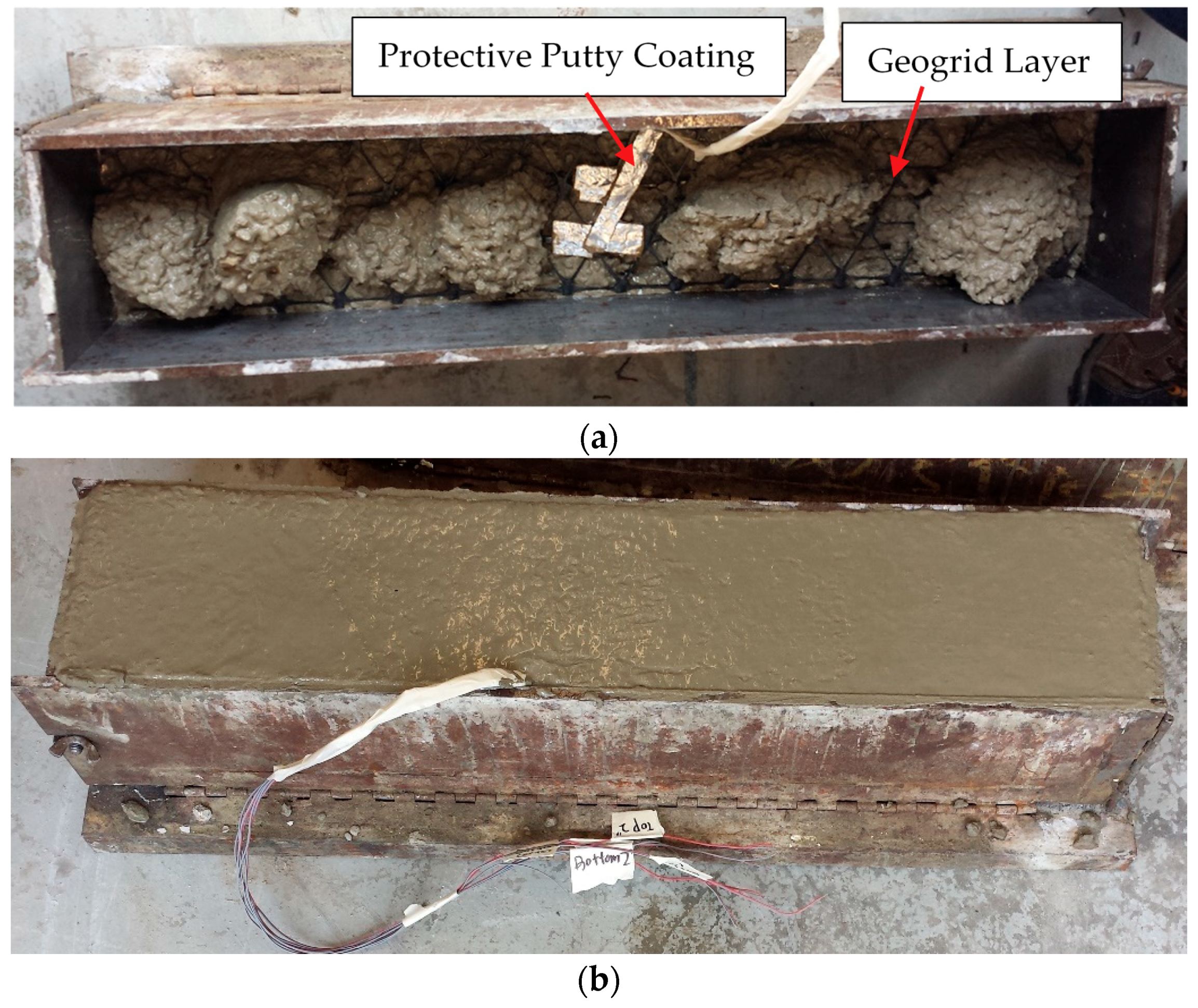
To investigate the potential benefits of geogrid reinforcement for plain concrete, unreinforced and geogrid-reinforced concrete beams were cast for four-point flexural bending tests in 152 mm × 152 mm × 762 mm steel molds (Figure 2a). For the geogrid-reinforced beams, the geogrid reinforcement was installed at the lower one-third depth of the beam, i.e., approximately 51 mm from the bottom of the beam. A concrete layer was first poured and compacted in the mold. The geogrid layer was then carefully installed and kept tight, and another concrete layer was cast above it (Figure 2a,b). It should be noted that, as the geogrid is light weight, it does not sink into fresh concrete even though no vertical reinforcement elements are utilized. In addition, the geogrid was prepared with dimensions to allow for a tight fit into the concrete steel mold. Thus, the geogrids could be securely placed in the steel mold without employing any extra measures. Extra care was exercised to compact the concrete to the extent possible to ensure a proper intermixing between the geogrids and surrounding concrete mixtures. After 24 h of room temperature curing, the concrete beams were demolded and moved into a water bath tank to cure for at least 28 days prior to testing. Upon demolding the specimens, the specimens were visually examined, and no visible separation or surface voids were observed. Two replicate specimens were fabricated for the respective unreinforced and reinforced beams.
2.3. Instrumentation and Flexural Loading Test
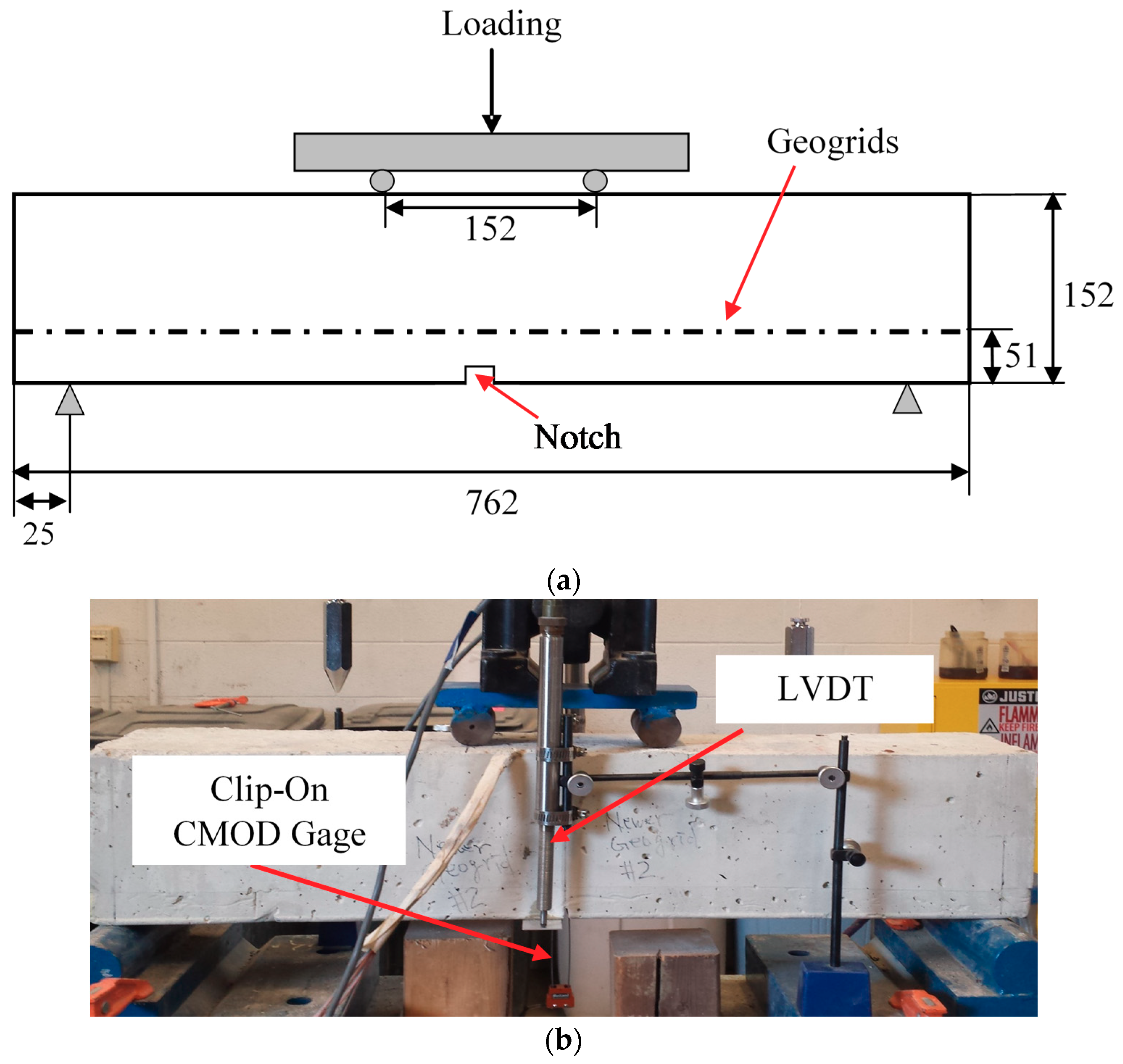
The setup and instrumentation of the four-point loading test is shown in Figure 3. All concrete beams have a support span of 712 mm and a loading span of 152 mm (Figure 3a). A 3 mm wide, 25 mm deep notch was sawed at the midpoint of the bottom face of the concrete beams to promote flexural failure close to the mid-span of the beam.
Two linear variable differential transformers (LVDTs) were installed at the midspan of the beam, with one on each side to measure midspan deflection during loading (Figure 3b). A clip-on gage (EDS-0500-500T-S, Reliant Technology LLC, Colorado Springs, CO, USA) was installed at the notch at bottom of midspan to measure the crack mouth opening displacement (CMOD) during loading (Figure 3b).
Additionally, for the reinforced concrete beams, the geogrid reinforcement was instrumented by strain gages to monitor strains developed in geogrids during flexural loading (Figure 1). An electrical resistance type strain gage (KFG-5-120-C1-11L3M3R, Omega Engineering Inc., Norwalk, CT, USA) was selected. The strain gage has a backing material constructed from polyimide, and the measurement grid is made of a constantan alloy that can sustain strains of up to 5%. For each geogrid, a total of 8 strain gages were installed along the centerline in the longitudinal direction of the beam. Strain gages were installed at the midspan and at various distances from the midspan: 25 mm, 51 mm, and 76 mm. Strain gages were installed in pairs on both the upper and lower surfaces of the geogrid ribs in order to minimize the effects of flexural deformation on strain measurements.
Due to the constrained surface areas of geogrid ribs and the flexible and planar structure of geogrids, it has been shown that installing the delicate strain gages on geogrids can be very challenging [25,26,27]. This study followed three main steps to install strain gages onto the geogrids, namely, surface preparation, gage attachment, and protective coating. Tang, 2011 [28] presents detailed information regarding the steps and procedures for installing strain gages on geogrids. As strain gages are delicate and prone to mechanical and moisture damage, a waterproof putty (PTK-26, Omega Engineering Inc., USA) was used to seal and protect the strain gages (Figure 2a). The putty was flexible enough not to cause unintended reinforcing effects on the geogrids and yet adequately tough to prevent mechanical damages. A thin layer of aluminum sheet was attached to the putty to provide additional protection from pointy aggregates (Figure 2a). Wires that connects strain gages were also protected by the same waterproof putty. All strain gages were still functional prior to the flexural loading tests.
The simply-supported concrete beams were subsequently loaded by using a close-loop electro-hydraulic actuator (Material Testing System Inc., Eden Prairie, MN, USA) housed in the Charles L. Bartholomew Civil Engineering Laboratory at Widener University. The monotonic static loading was applied under a displacement-control mode at a rate of 0.004 mm/s.
3. Results and Discussion
3.1. Load-Midspan Displacement Behavior and Failure Modes
Figure 4 shows the load-midspan displacement responses of the concrete beams to the flexural bending. Two replicate specimens were tested for both the unreinforced and geogrid-reinforced beams. The averaged maximum load is 3.7 kN and 3.5 kN for unreinforced and geogrid-reinforced beams, respectively, indicating that the geogrid in this study does not necessarily contribute to improving the peak flexural strength of plain concrete. However, in looking at Figure 4, it can be seen that the geogrid-reinforced beams carried additional load after the crack was initiated, reaching a maximum post-cracking load of 0.8 kN, or about 23% of the maximum load. It is noted that the maximum post-cracking load is relatively low compared to the maximum peak load. Unlike other unconventional discrete types of reinforcements such as fibers whose bonding with concrete is the primary contributor to the reinforcement, geogrids are continuous and planar-type reinforcements, and carry the majority of the post-crack load upon the initiation of cracks in concrete. Thus, for geogrid-reinforced concrete, its post-crack load-carrying capacity relies on the ultimate tensile strength of the geogrids embedded in the concrete. The polypropylene (PP) type of geogrid used in this study typically has a relatively low ultimate tensile strength compared to other types of geogrids materials such as polyester (PET) or high-density polyethylene (HDPE) [29]. It is expected that the post-crack load would increase substantially when multiple layers of geogrids are installed in the concrete.
Figure 4 also indicates that geogrid-reinforced specimens exhibit significant deformation before ultimate failure, most likely due to the geogrid’s ductility, while the deformation of the control specimen is minimal, as expected. Table 3 summarizes the results of the flexural four-point testing for the plain and geogrid-reinforced beams.
Based on the four-point bending tests, the flexural strength, also known as modulus of rupture, R can be determined according to the following equation [30]:
where: P is the maximum total load measured, units in kN; l is the support span length, 712 mm; b is the specimen width, 152 mm; h is the specimen height, 152 mm. It should be noted that the above equation was modified from the flexural strength equation for four-point loading where the loading span was exactly one third of the support span. As listed in Table 3, the averaged flexural strength for plain and reinforced concrete beams is 300 kPa and 284 kPa, respectively. It is noted that the single layer of geogrid used in this particular study did not necessarily increase the flexural strength of the concrete.
The area under the load-deflection curve in Figure 4 represents the static flexural energy absorption capacity of the concrete beams. The accumulated flexural energy for plain and geogrid-reinforced concrete is 6.8 J and 22.1 J, respectively. Embedding geogrids in the concrete results in a substantial improvement in the total energy-absorption capacity and the post-peak ductility under flexure. It is worth noting that, similar to carbon fiber ropes used for shear strengthening of reinforced concrete beams or steel fibers used in shear-dominated beams [31,32], limited past studies have demonstrated that geogrids as shear reinforcement in a hybrid form with steel fibers can enhance shear capacity and alter the failure mechanisms of beams from a brittle shear failure to a ductile flexural failure [19].
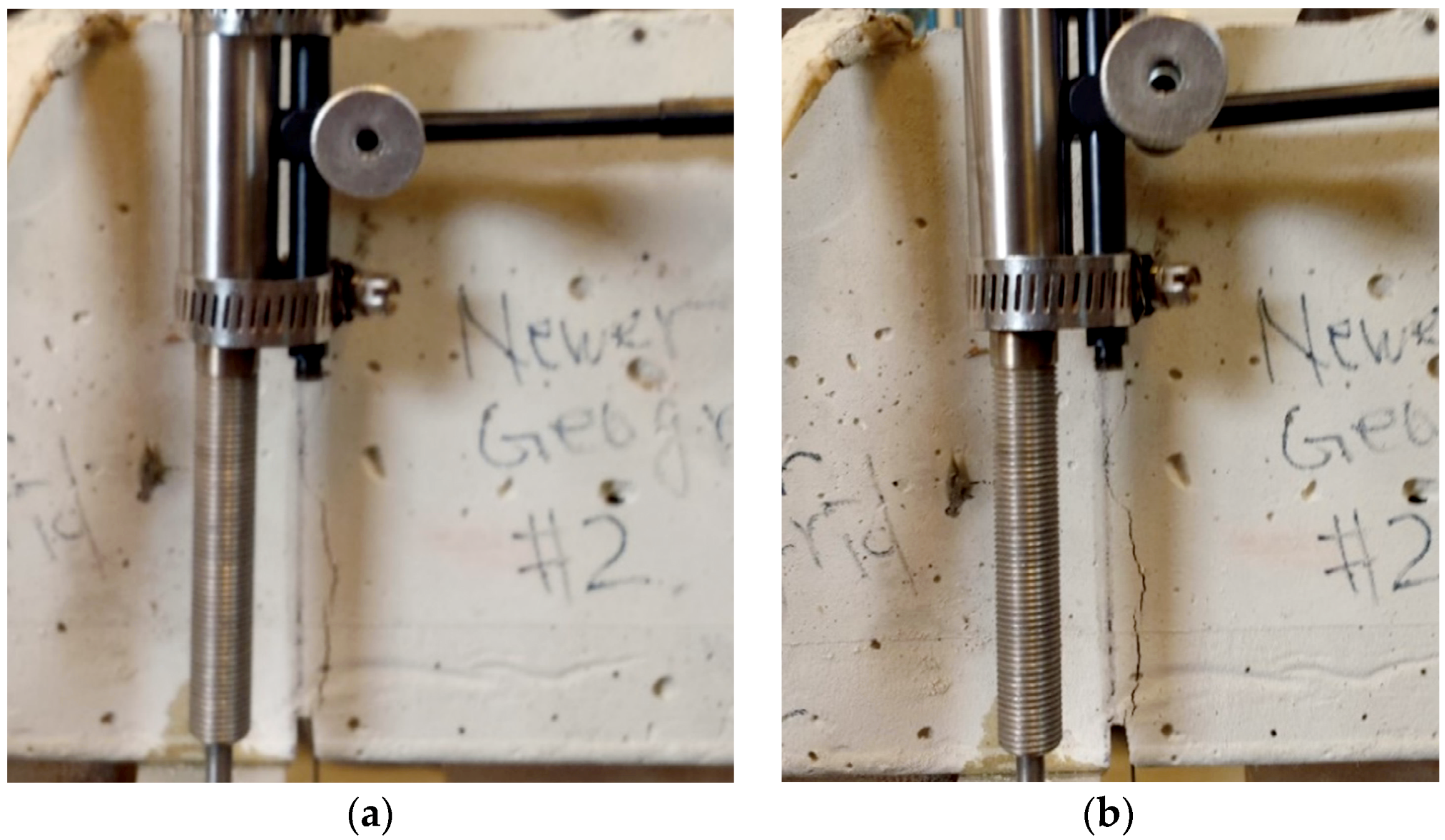
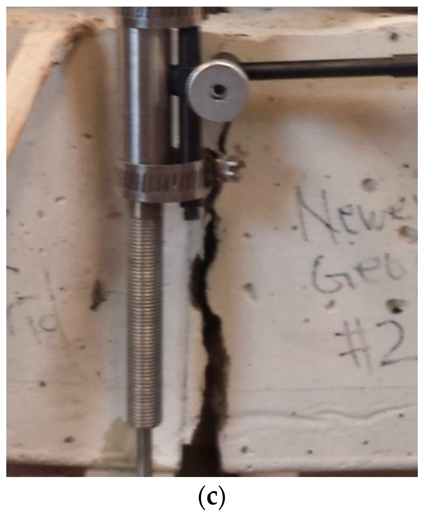
Observations from images of beams during loading and at failure show that, for the reinforced concrete beams, there was extensive crack propagation, with a wide crack mouth opening before failure (Figure 5); in contrast, the plain concrete beam failed instantly. For geogrid-reinforced beams, as shown in Figure 5, the geogrid was able to hold the concrete beam with a macrocrack, suggesting that embedding geogrids in plain concrete delay collapse failure. The geogrid-reinforced specimens exhibit more ductility, delayed cracking, and an increased strength after cracking. On the other hand, the failure mode and mechanism of the unreinforced control beam was observed to follow a brittle and sudden failure due to the lack of any reinforcement. The extensive post-cracking deformation of the geogrid-reinforced concrete beams shows that the inclusion of geogrids provides a certain degree of post-cracking ductility, which is desirable in most applications.
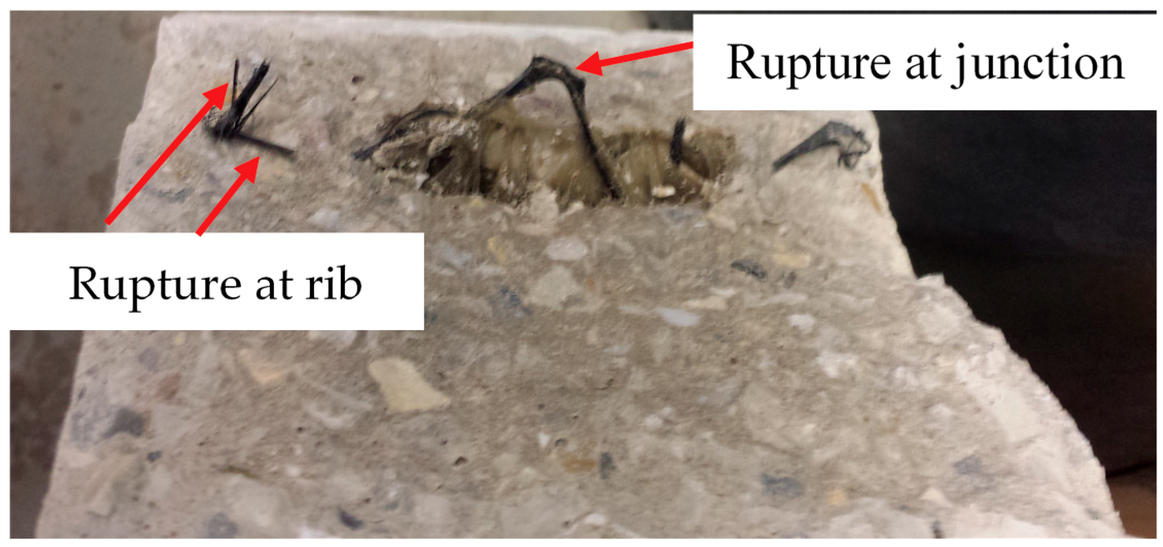
After the initial cracking, load is redistributed to the geogrids embedded at the lower portion of the beam. Based on pullout tests for geogrids embedded in concrete cement, a past study found that geogrids with roughened surfaces were able to provide surface frictional resistance force to cause a fracture failure of the geogrid instead of a pullout failure [33]. For the concrete specimens consisting of coarse aggregates in this study, in addition to frictional resistance along the geogrid’s surface, the developed passive stress against the geogrid’s bearing rib can provide pullout resistance. Geogrids were fractured at both the junctions and ribs, as depicted in Figure 6. No signs of slippage or pullout of geogrids were found upon a close examination of the geogrid surfaces post failure. This is further confirmed by the strain measurements in geogrids that are presented later.
3.2. Load-CMOD
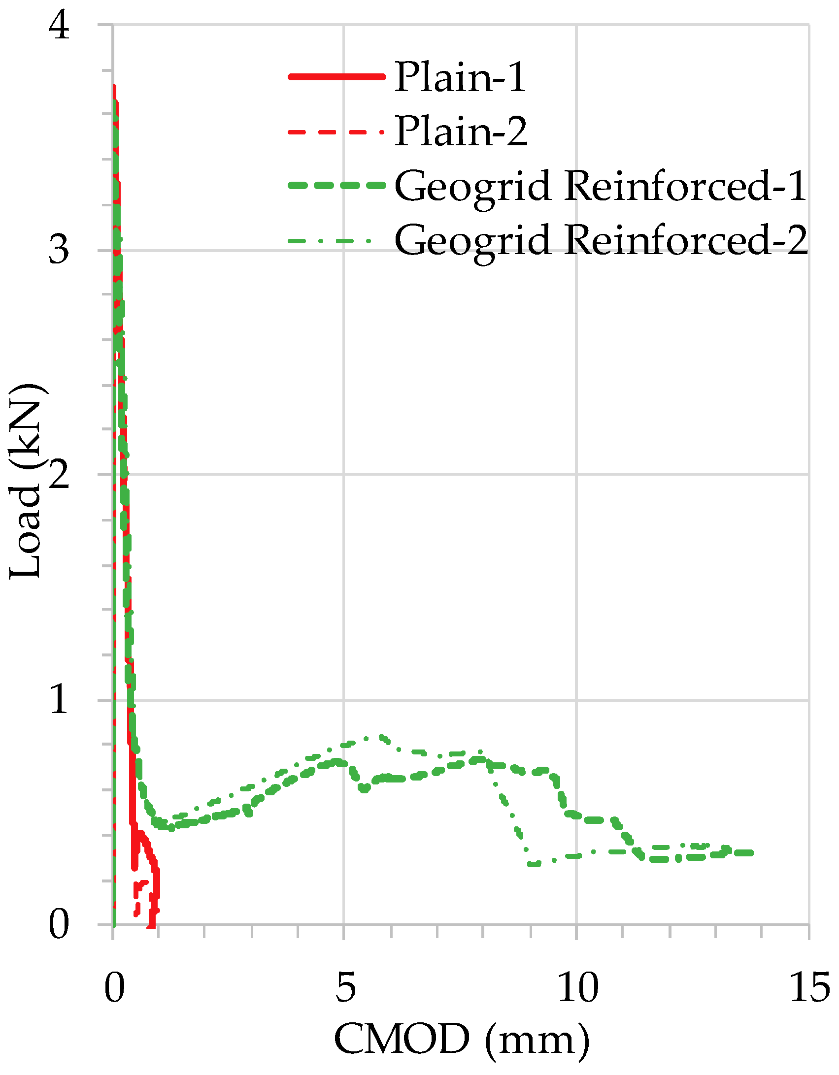
A clip-on gage was used to measure the crack mouth opening displacement (CMOD) at the notch of the beams. Figure 7 shows the CMOD measurements until collapse failure of the beams. The sudden drop of load, along with a significant increase of CMOD, indicates the initiation of cracking. As can be seen in Figure 7, extensive CMOD occurs for geogrid-reinforced concrete beams after the initial cracking, whereas the plain concrete beams exhibited very little CMOD, indicating an abrupt, brittle failure. This resembles the observations from images of beams during loading and at failure (Figure 5). As the load is redistributed to the geogrids after the initial cracking in concrete, the load increases gradually as geogrids elongate until a rupture of ribs or junctions occurs.
In contrast to the relatively low post-crack load of geogrid-reinforced concrete shown in Table 3, the significantly greater CMOD exhibited by geogrid-reinforced concrete suggests the promising potential of using geogrids for enhancing post-crack ductility of plain concrete. This also indicates the need to examine both the strength and deformation characteristics of the geogrids used in this study. A close examination of the stress-strain behavior of both the geogrids and concrete would shed light on the flexural behavior of geogrid-reinforced concrete, and help us better understand the effectiveness of using geogrids for reinforcing plain concrete. In addition, with properly defined stress-strain relationships for geogrids and concrete, it would enable sectional analysis of geogrid-reinforced concrete under flexure. Further, it has been established that the addition of fiber reinforcement in concrete in the form of fiber grids [16] or discrete fibers [34] significantly improves the overall post-cracking response, and the implementation of this favorable behavior in numerical simulations provides rational and accurate analytical results concerning the curvature ductility and the resisting bending moment of flexural structural members.
3.3. Strain Developed in Geogrids
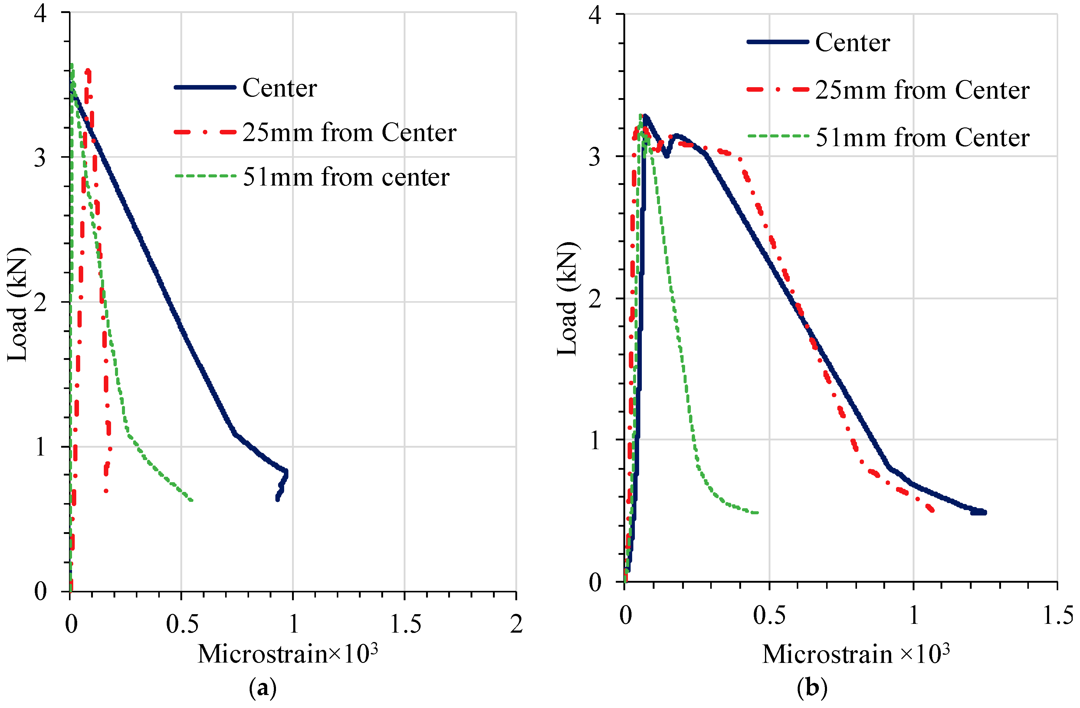
Strain gauges were installed in pairs on the top and bottom surfaces of a geogrid rib, and the measurements were averaged in order to take into consideration strain measurements caused by flexural bending, and to obtain the tensile strain in geogrids. Strain gages were installed at the center and at various distances from the center: 25 mm, 51 mm, and 76 mm. Figure 8 shows the tensile strain developed in geogrids during loading for both geogrid-reinforced specimens. It was observed from both of the geogrid-reinforced specimens that no measurable strains developed at 76 mm from the center of the beam. Thus, it is likely that geogrids were not mobilized at locations whose distances are greater than 76 mm from the center along the longitudinal direction. As the loading span of the test setup is 152 mm or 76 mm from each side of the center in longitudinal direction (Figure 3a), it appears that the geogrids were mobilized to exhibit measurable strains only within the area under the loading span or the zone of the maximum bending moment.
Additionally, as shown in Figure 8, all of the geogrids were activated and mobilized instantly upon the application of the flexural load. With the exception of the location that is 25 mm from the center in specimen 1, for each respective concrete beam, the strain measurements at all locations are approximately the same until the peak load or the initial cracking. This suggests that the geogrids in each of the concrete beams were uniformly mobilized, and that the geogrids embedded in concrete acted as a whole without slippage or pullout from the concrete. After the peak load or the initial cracking, most of the tensile force is transferred to the geogrids, and strains were not uniformly developed or distributed, as seen in Figure 8. As expected, more strains developed in geogrids at locations closer to the center after the initial cracking.
4. Conclusions and Recommendations
Although geogrids have traditionally been used for reinforcing unbound geomaterials in earthen structures, a limited number of studies have suggested potential benefits of their use in plain Portland cement concrete (PCC). This study conducted four-point bending tests to investigate the flexural behavior of geogrid-reinforced concrete beams and examine the benefits of geogrid reinforcement for PCC concrete. In addition to midspan deflection and CMOD, strain gages were used to measure the strains that developed in geogrids.
Load-midspan deflection responses show that the geogrid primarily contributes to altering the post-cracking behavior of plain concrete. Geogrid-reinforced specimens exhibit significant deformation after the initial cracking and before ultimate failure, likely due to the geogrid’s ductility, while the deformation of the plain concrete beams is minimal, as expected. Failure mode and mechanism of the unreinforced control beam was observed to follow a brittle and sudden failure due to the lack of any reinforcement. Observations of the beams’ failure modes also confirms that the geogrid was able to hold the concrete beam with a macrocrack and delay the collapse failure, while the unreinforced plain concrete beams follow an abrupt brittle failure. Embedding geogrids in concrete results in a substantial improvement in total energy-absorption capacity. However, the single geogrid layer used in this particular study did not contribute to improving the flexural strength of the concrete beams.
Measurements from strain gages attached on various locations of geogrids suggest that the geogrid was activated and mobilized instantaneously upon the application of four-point flexural loading. The geogrids appear to be mobilized to exhibit measurable strains only within the area under the loading span, or the zone of the maximum bending moment. Both the strain measurements and observations of the geogrids post failure suggest that there was no slippage or pullout between the geogrids and the concrete.
As only one type of geogrid, a triaxial geogrid was investigated in this study, it is recommended that more types of geogrids (e.g., uniaxial and biaxial geogrids) be tested to examine their potential benefits for PCC. While this study used only one layer of geogrids, embedding multiple layers is expected to enhance the performance of geogrids as reinforcement. It may also be of interests to investigate geogrid reinforcement for PCC under cyclic loading. It is worth noting that there are potential limitations in using geogrids for Portland cement concrete. Geogrids should not be used in concrete structures or members that may be exposed to fire or high-temperature environments, because geogrids are sensitive to temperature changes. Additionally, as geogrids are made of polypropylene (pp) materials that exhibit time-dependent viscoelastic or viscoplastic behavior, it is possible that geogrids may yield under sustained long-term loading when embedded in concrete.
Author Contributions
Conceptualization and Data Analysis, X.T.; Experimental Investigation and Data Analysis, I.H.; Concrete Mixture Design and Assisting in Laboratory Tests, M.N.J.; Writing-Original Draft Preparation, X.T.; Supervision, X.T.
Funding
This research received no external funding.
Acknowledgments
The authors wish to thank Andrew Nodolski for assisting with laboratory tests. Donation of the geogrids from Tensar International Inc. is gratefully acknowledged.
Conflicts of Interest
The authors declare no conflict of interest.
References
- McCormac, J.; Brown, R. Design of Reinforced Concrete, 10th ed.; Wiley: Hoboken, NJ, USA, 2016; ISBN 1118879104. [Google Scholar]
- Clarke, J.L. Alternative Materials for the Reinforcement and Prestressing of Concrete; CRC Press: New York, NY, USA, 1993; ISBN 9780751400076. [Google Scholar]
- Bakis, C.E.; Bank, L.C.; Brown, V.L.; Cosenza, E.; Davalos, J.F.; Lesko, J.J.; Machida, A.; Rizkalla, S.H.; Triantafillou, T.C. Fiber-Reinforced Polymer Composite for Construction—State-of-the-Art Review. J. Compos. Construct. 2002, 6, 73–87. [Google Scholar] [CrossRef]
- Erki, M.A.; Rizkalla, S.H. FRP Reinforcement for Concrete Structures. Concr. Int. 1993, 15, 48–53. [Google Scholar]
- Banthia, N.; Al-Asaly, M.; Ma, S. Behavior of Concrete Slabs Reinforced with Fiber-Reinforced Plastic Grid. J. Mater. Civ. Eng. 1995, 7, 252–257. [Google Scholar] [CrossRef]
- Bentur, A.; Mindess, S. Fibre Reinforced Cementitious Composites; Elsevier Applied Science: New York, NY, USA, 1990. [Google Scholar]
- Zollo, R.F. Fiber-Reinforced Concrete: An Overview after 30 years of Development. Cem. Concr. Compos. 1997, 19, 107–122. [Google Scholar] [CrossRef]
- American Concrete Institute (ACI). State-Of-The-Art Report on Fiber Reinforced Concrete; ACI Committee 544; ACI: Detroit, MI, USA, 2002. [Google Scholar]
- Yin, S.; Tuladhar, R.; Shi, F.; Combe, M.; Collister, T.; Sivakugan, N. Use of Macro Plastic Fibres in Concrete: A Review. Construct. Build. Mater. 2015, 93, 180–188. [Google Scholar] [CrossRef]
- Singh, H. Flexural Modeling of Steel Fiber-Reinforced Concrete Members: Analytical Investigations. Pract. Period. Struct. Des. Construct. 2015, 20. [Google Scholar] [CrossRef]
- Jewell, R.A.; Milligan, G.W.E.; Sarsby, R.W.; Dubois, D. Interaction between Soil and Geogrids. In Proceedings of the Conference on Polymer Grid Reinforcement in Civil Engineering; Thomas Telford Publishing: London, UK, 1984; pp. 18–30. [Google Scholar]
- Tang, X.; Chehab, G.; Palomino, A.M. Evaluation of Geogrids for Stabilizing Weak Pavement Subgrade. Int. J. Pavement Eng. 2008, 9, 413–429. [Google Scholar] [CrossRef]
- Tang, X.; Abu-Farsakh, M.; Shadi Hanandeh, S.; Chen, Q. Performance of Reinforced/Stabilized Unpaved Test Sections Built over Native Soft Soil under Full-Scale Moving Wheel Loads. Transp. Res. Rec. J. Transp. Res. Board 2015, 2511, 81–89. [Google Scholar] [CrossRef]
- Tang, X.; Chehab, G.; Kim, S. Laboratory Study of Geogrid Reinforcement in Portland Cement Concrete. In Proceedings of the 6th RILEM International Conference on Cracking in Pavements 2008, Chicago, IL, USA, 16–18 June 2008; pp. 769–778. [Google Scholar]
- El Meski, F.; Chehab, G.R. Flexural Behavior of Concrete Beams Reinforced with Different Types of Geogrids. J. Mater. Civ. Eng. 2014, 26. [Google Scholar] [CrossRef]
- Itani, H.; Saad, G.; Chehab, G. The Use of Geogrid Reinforcement for Enhancing the Performance of Concrete Overlays: An Experimental and Numerical Assessment. Construct. Build. Mater. 2016, 124, 826–837. [Google Scholar] [CrossRef]
- Al-Hedad, A.S.A.; Hadi, M.N.S. Effects of Geogrid Reinforcement on the Flexural Behavior of Concrete Pavements. Road Mater. Pavement Des. 2018. [Google Scholar] [CrossRef]
- Chidambaram, R.S.; Agarwal, P. The Confining Effect of Geo-Grid on the Mechanical Properties of Concrete Specimens with Steel Fiber under Compression and Flexure. Construct. Build. Mater. 2014, 71, 628–637. [Google Scholar] [CrossRef]
- Chidambaram, R.S.; Agarwal, P. Flexural and Shear Behavior of Geogrid Confined RC Beams with Steel Fiber Reinforced Concrete. Construct. Build. Mater. 2015, 78, 271–280. [Google Scholar] [CrossRef]
- Al-Hedad, A.S.A.; Bambridge, E.; Hadi, M.N.S. Influence of Geogrid on the Drying Shrinkage Performance of Concrete Pavements. Construct. Build. Mater. 2017, 146, 165–174. [Google Scholar] [CrossRef]
- Tang, X.; Palomino, A.M.; Stoffels, S.M. Reinforcement Tensile Behavior Under Cyclic Moving Wheel Loads. Transp. Res. Rec. J. Transp. Res. Board 2013, 2363, 113–121. [Google Scholar] [CrossRef]
- Tang, X.; Stoffels, S.M.; Palomino, A.M. Resilient and Permanent Deformation Characteristics of Unbound Pavement Layers Modified by Geogrids. Transp. Res. Rec. J. Transp. Res. Board 2013, 2369, 3–10. [Google Scholar] [CrossRef]
- Environmental Protection Agency (EPA). SW-846 Test Method 9090A: Compatibility Test for Wastes and Membrane Liners; EPA: Washington, DC, USA, 1992.
- Tensar International. Product Specification—TriAxTM TX160 Geogrid; Tensar International: Atlanta, GA, USA, 2009. [Google Scholar]
- Brandon, T.L.; Al-Qadi, I.L.; Lacina, B.A.; Bhutta, S.A. Construction and Instrumentation of Geosynthetically Stabilized Secondary Road Test Sections. Transp. Res. Rec. J. Transp. Res. Board 1996, 1534, 50–57. [Google Scholar] [CrossRef]
- Maxwell, S.; Kim, W.H.; Edil, T.B.; Benson, C.H. Geosynthetics in Stabilizing Soft Subgrade with Breaker Run; Report No. 0092-45-15; Wisconsin Department of Transportation: Madison, WI, USA, 2005. [Google Scholar]
- Warren, K.A.; Brooks, J.A.; Howard, I.L. Foil Strain Gage Attachment Techniques for Geotextile and Geogrid. In Proceedings of the Geocongress 2006: Geotechnical Engineering in the Information Technology Age, Atlanta, GA, USA, 26 February–1 March 2006; pp. 1–6. [Google Scholar]
- Tang, X. A Study of Permanent Deformation Behavior of Geogrid-Reinforced Flexible Pavements Using Small Scale Accelerated Pavement Testing. Ph.D. Thesis, The Pennsylvania State University, University Park, PA, USA, May 2011. [Google Scholar]
- Shinoda, M.; Bathurst, R.J. Lateral and Axial Deformation of PP, HDPE and PET Geogrids under Tensile Load. Geotext. Geomembr. 2004, 22, 205–222. [Google Scholar] [CrossRef]
- ASTM C 78. Standard Test Method for Flexural Strength of Concrete (Using Simple Beam with Third-Point Loading); Annual Book of ASTM Standards; American Society for Testing and Materials (ASTM): West Conshohocken, PA, USA, 2018; Volume 4.02. [Google Scholar]
- Chalioris, E.C.; Kosmidou, P.-M.; Papadopoulos, N.A. Investigation of a New Strengthening Technique for RC Deep Beams Using Carbon FRP Ropes as Transverse Reinforcements. Fibers 2018, 6, 52. [Google Scholar] [CrossRef]
- Chalioris, E.C. Analytical Approach for the Evaluation of Minimum Fibre Factor Required for Steel Fibrous Concrete Beams under Combined Shear and Flexure. Construct. Build. Mater. 2013, 43, 317–336. [Google Scholar] [CrossRef]
- Swamy, R.N.; Jones, R.; Oldroyd, P.N. The behavior of Tensar Reinforced Cement Composites under Static Loads. In Proceedings of the Conference on Polymer Grid Reinforcement in Civil Engineering; Thomas Telford Publishing: London, UK, 1984; pp. 222–232. [Google Scholar]
- Chalioris, C.E.; Panagiotopoulos, T.A. Flexural Analysis of Steel Fibre Reinforced Concrete Members. Comput. Concr. 2018, 22, 11–25. [Google Scholar]
Figure 1.
Geogrid specimen with strain gages attached on ribs at various location.

Figure 2.
Fabrication of geogrid-reinforced beams: (a) cast the second layer of concrete mixture upon placing the geogrid; (b) finished concrete beam specimen with strain gages wires labelled.
Figure 2.
Fabrication of geogrid-reinforced beams: (a) cast the second layer of concrete mixture upon placing the geogrid; (b) finished concrete beam specimen with strain gages wires labelled.

Figure 3.
Test setup and instrumentation: (a) schematic and dimensions of test setup, units in mm; (b) instrumentation of tests.
Figure 3.
Test setup and instrumentation: (a) schematic and dimensions of test setup, units in mm; (b) instrumentation of tests.

Figure 4.
Load-midspan deflection of concrete beams under monotonic flexural loading.

Figure 5.
Failure mode of geogrid-reinforced concrete beams: (a) crack initiation; (b) crack propagation; (c) macrocrack with large CMOD.
Figure 5.
Failure mode of geogrid-reinforced concrete beams: (a) crack initiation; (b) crack propagation; (c) macrocrack with large CMOD.


Figure 6.
Rupture failure of geogrid.

Figure 7.
Load-CMOD behavior.

Figure 8.
Strain developed in geogrids at various locations from center: (a) geogrid-reinforced specimen 1; (b) geogrid-reinforced specimen 2.
Figure 8.
Strain developed in geogrids at various locations from center: (a) geogrid-reinforced specimen 1; (b) geogrid-reinforced specimen 2.


Table 1.
Concrete mix design (kg/m3).
| Component | Material Type | Content (kg/m3) |
|---|---|---|
| Cement | ASTM Type I | 509 |
| Fine Aggregates | River Sand | 857 |
| Coarse Aggregates | Crushed Limestone | 1002 |
Table 2.
Index and mechanical properties of geogrids [24].
Table 2.
Index and mechanical properties of geogrids [24].
| Properties | Longitudinal | Diagonal | Transverse | General |
|---|---|---|---|---|
| Index Properties | ||||
| Rib Pitch (mm) | 40 | 40 | _ | _ |
| Mid-Rib Depth (mm) | _ | 1.8 | 1.5 | _ |
| Mid-Rib Width (mm) | _ | 1.1 | 1.3 | _ |
| Nodal Thickness (mm) | _ | _ | _ | 3.1 |
| Structural Integrity | ||||
| Junction Efficiency (%) | _ | _ | _ | 93 |
| Aperture Stability (kg-cm/deg. @ 5.0 kg-cm | _ | _ | _ | 3.6 |
| Radial Stiffness at Low Strain, kN/m @ 0.5% strain | _ | _ | _ | 300 |
Table 3.
Results of flexural tests on concrete beams.
| Concrete Specimen | Maximum Load (kN) | Post-Cracking Maximum Load (kN) | Flexural Strength (kPa) | Accumulated Flexural Energy (J) |
|---|---|---|---|---|
| Plain Concrete | 3.7 | - | 300 | 6.8 |
| Geogrid-Reinforced | 3.5 | 0.8 | 284 | 22.1 |
© 2018 by the authors. Licensee MDPI, Basel, Switzerland. This article is an open access article distributed under the terms and conditions of the Creative Commons Attribution (CC BY) license (http://creativecommons.org/licenses/by/4.0/).
Share and Cite
MDPI and ACS Style
Tang, X.; Higgins, I.; N. Jlilati, M. Behavior of Geogrid-Reinforced Portland Cement Concrete under Static Flexural Loading. Infrastructures 2018, 3, 41. https://0-doi-org.brum.beds.ac.uk/10.3390/infrastructures3040041
AMA Style
Tang X, Higgins I, N. Jlilati M. Behavior of Geogrid-Reinforced Portland Cement Concrete under Static Flexural Loading. Infrastructures. 2018; 3(4):41. https://0-doi-org.brum.beds.ac.uk/10.3390/infrastructures3040041
Chicago/Turabian StyleTang, Xiaochao, Isaac Higgins, and Mohamad N. Jlilati. 2018. "Behavior of Geogrid-Reinforced Portland Cement Concrete under Static Flexural Loading" Infrastructures 3, no. 4: 41. https://0-doi-org.brum.beds.ac.uk/10.3390/infrastructures3040041