1. Introduction
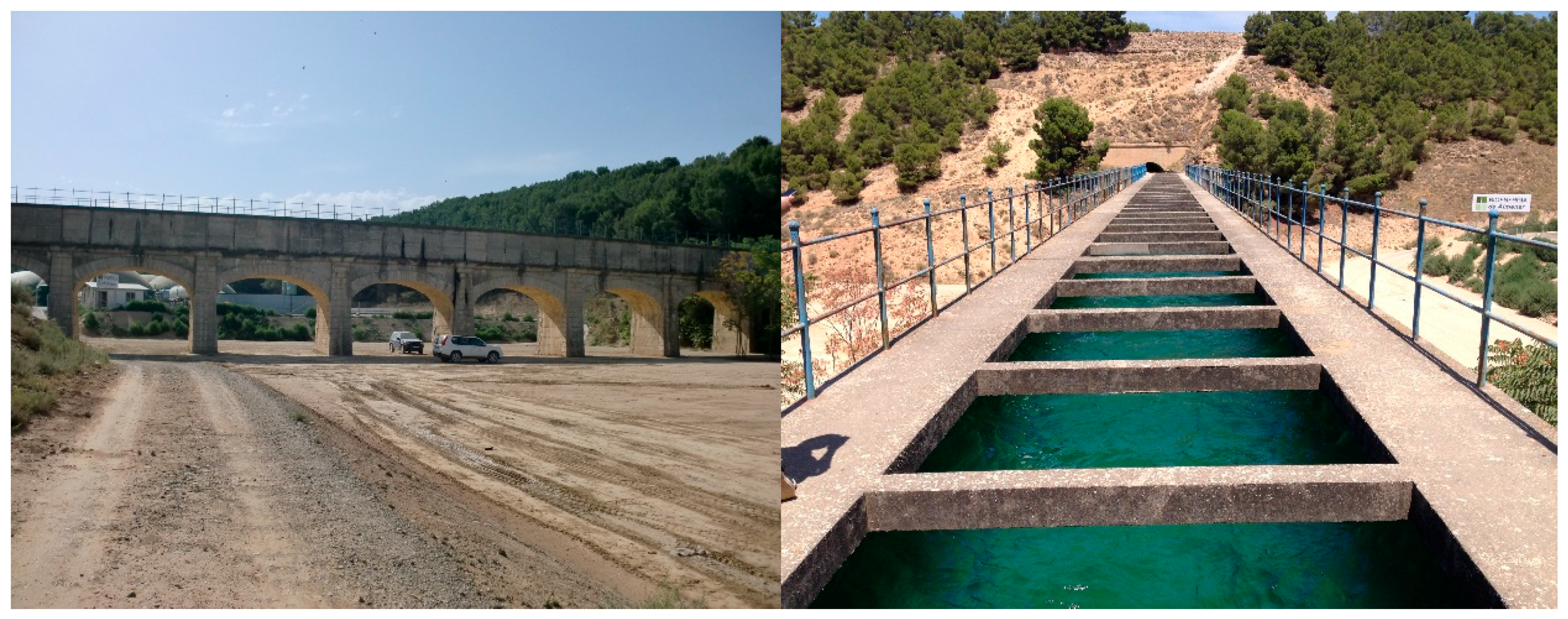
The Canal of Aragon and Catalonia (CAyC) is a hydraulic infrastructure of national interest built in 1906. The canal collects water from the Ésera River and it is used for agricultural purposes, water supply in urban areas and industries and hydroelectric energy generation.
Water regulation and usage has significantly changed since the beginning of the 20th century and, consequently, the canal has been subjected to refurbishment to improve coatings and increase the cross-section of the main canal and irrigation ditches. The aqueducts assessed in this study are an example of this evolution and refurbishment.
The Interministerial Commission of Hydraulic Plans agreed in 1960 on the construction of the Liaison Canal that complements the water supply of the Ésera River with water from the adjacent hydraulic basin, the Noguera-Ribagorzana. This Liaison Canal covers 44,000 Ha, has a capacity of 26.1 m3/s and connects with the CAyC at the km 66. Due to the connection of the two canals, an extension downstream of this point was required to increase the capacity of the latter (CAyC) whose capacity was limited to 12.42 m3/s.
Two aqueducts downstream the connection point, Coll de Foix Aqueduct (
Figure 1) and Capdevila Aqueduct (
Figure 2) present design flows of 26.1 m
3/s and 25.7 m
3/s, respectively. These design flows do not correspond with the current real capacity, which approaches 21.9 m
3/s in Coll de Foix. Under these circumstances, the need to increase the hydraulic capacity of both aqueducts is mandatory to maximise its usage.
Currently, an expansion of the section of the canal is envisaged to tackle the loss of hydraulic capacity due to: (1) a roughness coefficient different from that foreseen in the original project; (2) a variation of the hydraulic slope downstream of both aqueducts; and (3) an increase in the water demands of the users, which translates into the need to increase the circulating flow.
The objective of this paper is to raise and analyse the structural feasibility of expanding the sections in order to increase their hydraulic capacity. For this purpose, a survey of damages, topographic and geotechnical studies and structural analysis with non-linear models has been carried out. Fortunately, the original project of D. Félix de los Ríos Martín [
1] and of two projects of D. Fernando Hué Herrero [
2,
3] is available. The technical interest of this work lies in the study of a concrete structure with more than 100 years in service, designed with different structural safety approaches, and whose results will serve as a reference for interventions in similar works. It has been proven that the structural capacity of the former cross-section permits an increase of the loads without requiring an additional concrete reinforcement. The global intervention project can be found in [
4].
2. Geometry and Materials
2.1. Vaults and Spandrels
The Coll de Foix aqueduct is composed of a line of seven elliptical arches spanning 8.50 m reduced to 1/4, comprised between six piles and two abutments that longitudinally delimit the aqueduct to 69.70 m. On the other hand, the Capdevila aqueduct is 79.20 m long and has eight elliptical arches spanning 8.30 m and equally reduced to 1/4 of the span.
The arches are made of plain concrete composed of 250 kg/m3 of slow-setting Portland cement. The thickness of the arches in the key is 0.50 m and increases progressively towards the haunches to a thickness of 0.70 m. The average compressive strength values obtained from cores extracted from the aqueduct arches of Coll de Foix and Capdevila are 42 N/mm2 and 22 N/mm2, respectively.
The spandrel walls are composed of pressed brick, these breaking continuity between contiguous arches through projecting pilasters that form the abutments. The arrangement of reduced elliptical arches leads to reduced spandrel walls surfaces, thus making a backfill of concrete with 100 kg/m3 of natural cement economically viable. This alternative to the classic compacted granular filler allows to minimize the risk of leaks due to water losses from the bottom slab of the canal, which would increase the lateral pressures in the spandrel walls. In turn, the fact that both have similar stiffness is favorable for the arch-backfill interaction.
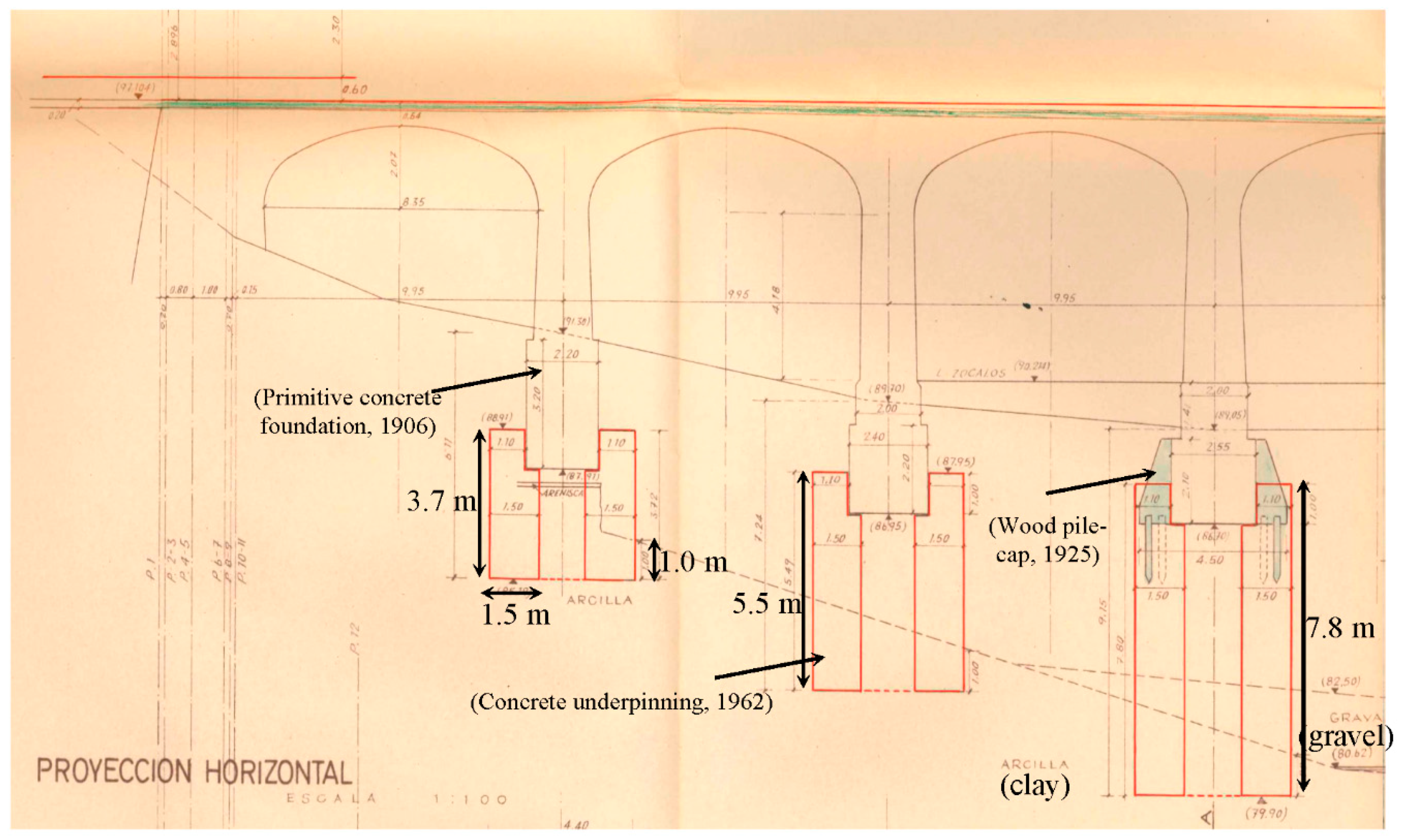
2.2. Piers and Foundations
The vertical piers are pyramid-shaped to increase stability, with 4% and 6% of lateral inclination and in the fronts formed by the abutments. The height ranges from 1.00 to 6.20 m starting from the foundations to the start of the arches. At the ends, the aqueducts are supported by abutments founded on soft sandstone and that delimit the aqueducts longitudinally. The filling of the piles and abutments is made of plain concrete with 225 kg/m3 of natural cement.
The primitive foundations are rectangular and made of concrete with 160 kg/m
3 of natural cement. Although, only Coll de Foix aqueduct maintains the original foundations since they are still referred to the layer of compact clays since its execution. On the other hand, in the Capdevila aqueduct it was necessary to reinforce, on two occasions, the foundation of some of its piers. In 1925, a stack of wooden piles was made only in pier 3 (
Figure 3), which proved to be insufficient because it did not reach the competent stratum. In the 1962 project [
3] the definitive recesses of piers 1–6 were designed and executed with concrete caissons of sufficient depth to reach the competent stratum of compact clays.
The average compressive strength obtained from the cores drilled from the foundations are 20 N/mm2 in both aqueducts.
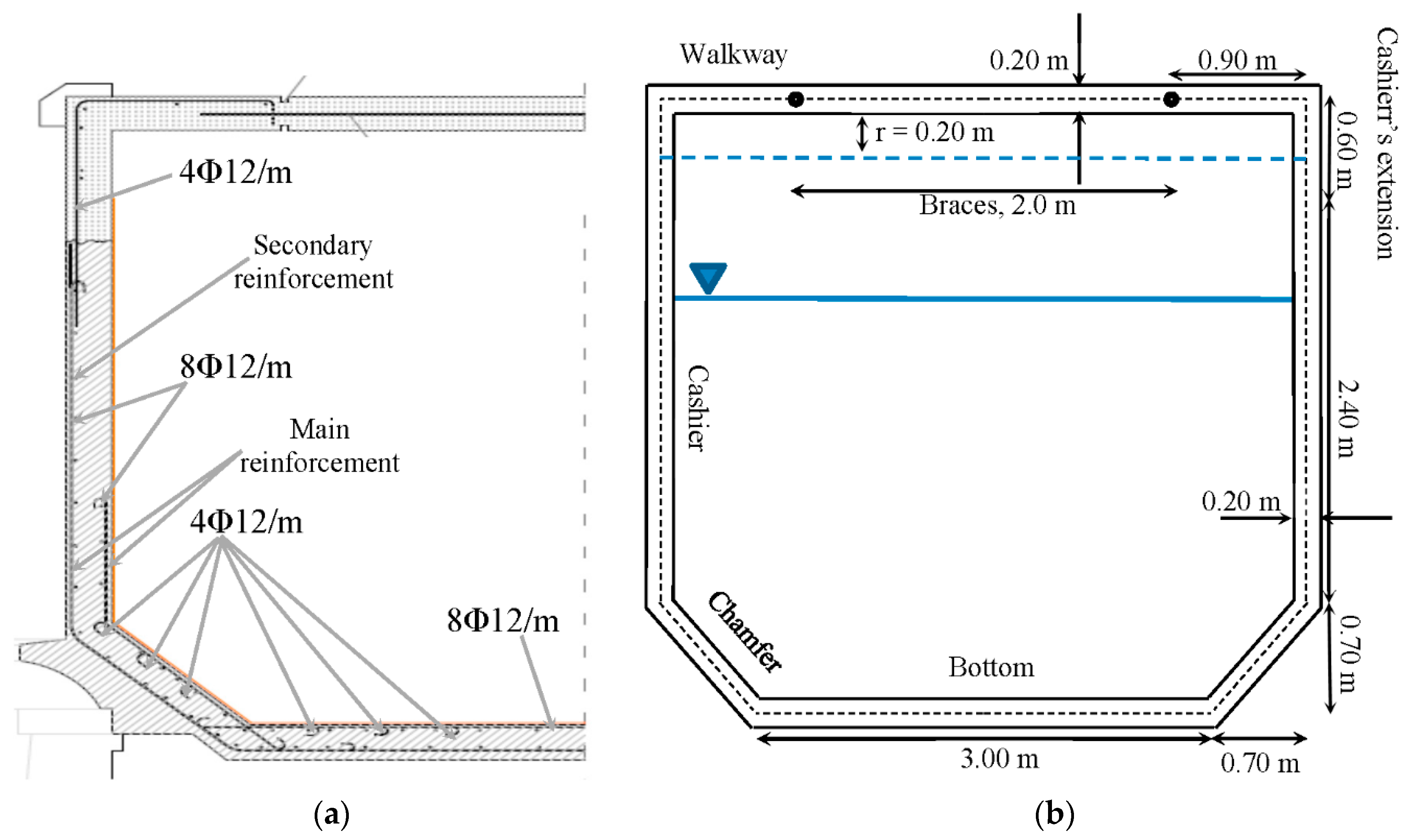
2.3. Canal
The section of the canal is constant in both aqueducts (
Figure 4) and consists of a slab of 3.00 m wide supported onto the backfill of the arches and joins the cashiers through chamfers of 0.70 m. The cross section is braced on the top by reinforced concrete braces with a rectangular cross-sections of 0.2 × 0.2 m
2 each 2.0 m in the longitudinal direction. The original height of the cross section is 2.40 m and the proposal is to increase it 0.60 m. All the elements of the canal have a thickness of 0.20 m.
On the one hand, the canal was built with vibrated hydraulic concrete with a content of 300 kg/m3 of artificial Portland cement. The strengths obtained from cores extracted from the aqueducts of Coll de Foix and Capdevila are 45 N/mm2 and 30 N/mm2, respectively. On the other hand, the reinforcement consists of smooth steel bars with a minimum yield stress (fy) of 240 N/mm2. The reinforcement of the extension consists of B500 steel rebars (fyk = 500 Mpa) and macro-polypropylene structural fibres mixed with the concrete (fck = 30 N/mm2). The characteristic flexural residual strength provided by the fibres are fR1k ≥ 1.50 N/mm2 and fR3k ≥ 1.50 N/mm2.
The proposed extension entails an increase of the hydraulic section of 19.1% of the final section (13.1 m2) with respect to the current one (11.0 m2) maintaining a clearance (r) of 0.20 m. This extension implies an increase of 8.5% in permanent loads (empty channel) and 10.0% in service (full channel, r = 0.0 m).
3. Structural Capacity of the Expanded Canal
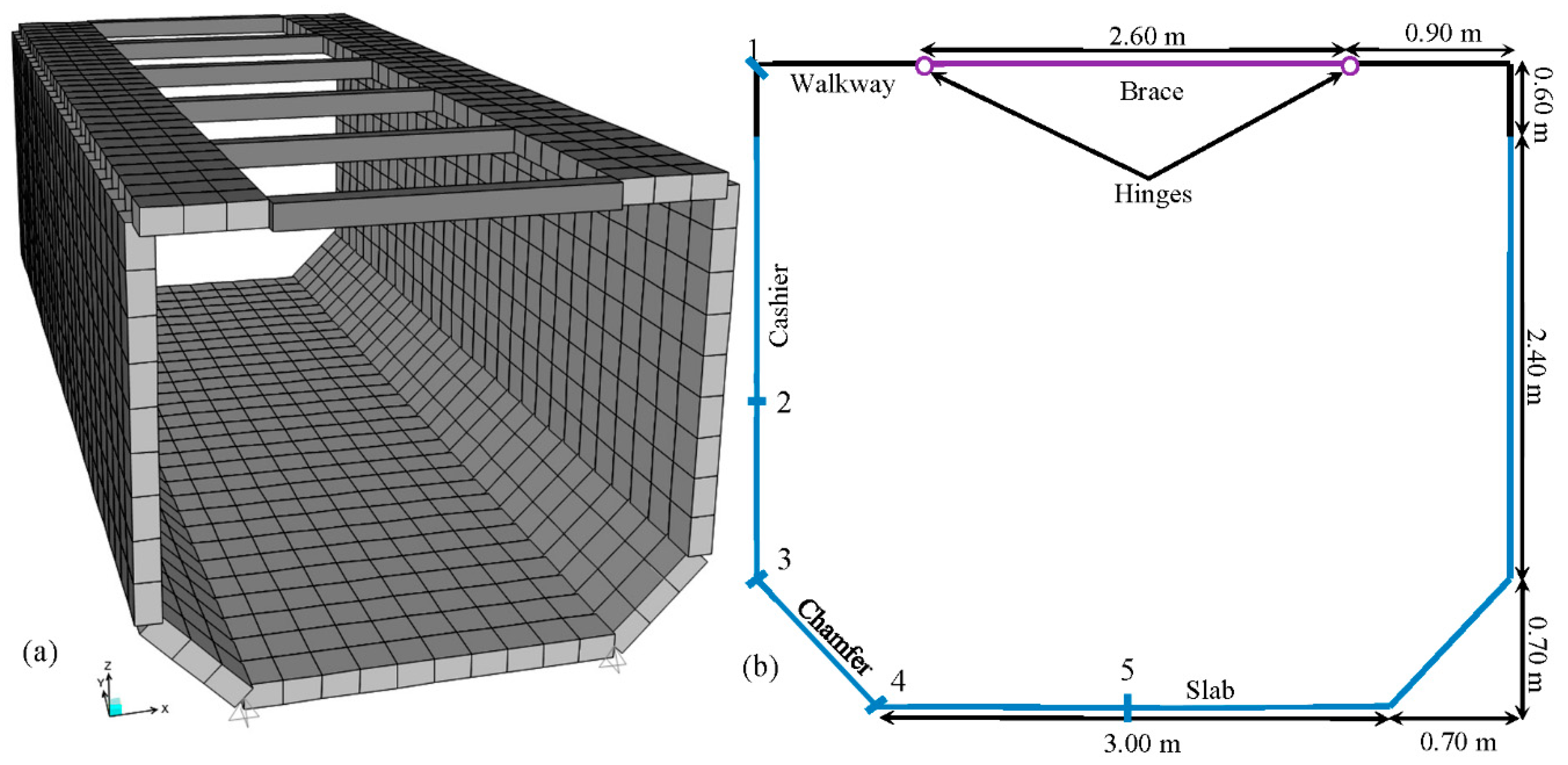
3.1. Geometry Simulation
A 3D finite element model (
Figure 5) was implemented with SAP2000
® v16 [
5] considering the geometry of the canal cross-section (
Figure 4). A 10.0 m length module of canal (distance between piles) was simulated with shell elements, except for the concrete braces that were represented with beam elements.
The boundary conditions considered were: (1) the connection slab-chamfer is simulated as a simply-supported point with free rotation in the plane that contains the cross-section and with fully-restrained displacement in the three spatial directions. This condition is representative in view of the existence of a lateral overhang that restricts the displacements. (2) The interaction between the slab and the backfill has been simulated by considering that downward displacements are restricted while upwards displacements are free; however, it has been proven that, for all load combinations, the slab detaches from the backfill. (3) The connection between the walkways and braces is represented by means of a perfect plastic hinge.
3.2. Loads and Load Combinations
The loads considered were: (1) self-weight (G). (2) Water circulating inside the canal (Qk,1). (3) Life load applied to the walkways (Qk,2) with a magnitude of 5.0 kN/m2. (4) Wind load applied to the external lateral surfaces of the cashiers (Qk,3) consisted of a uniformly-distributed load with a magnitude of 1.02 kN/m2 that can be either pressure or suction depending on the wind direction.
The following load combinations were assumed:
3.3. Service Limit States
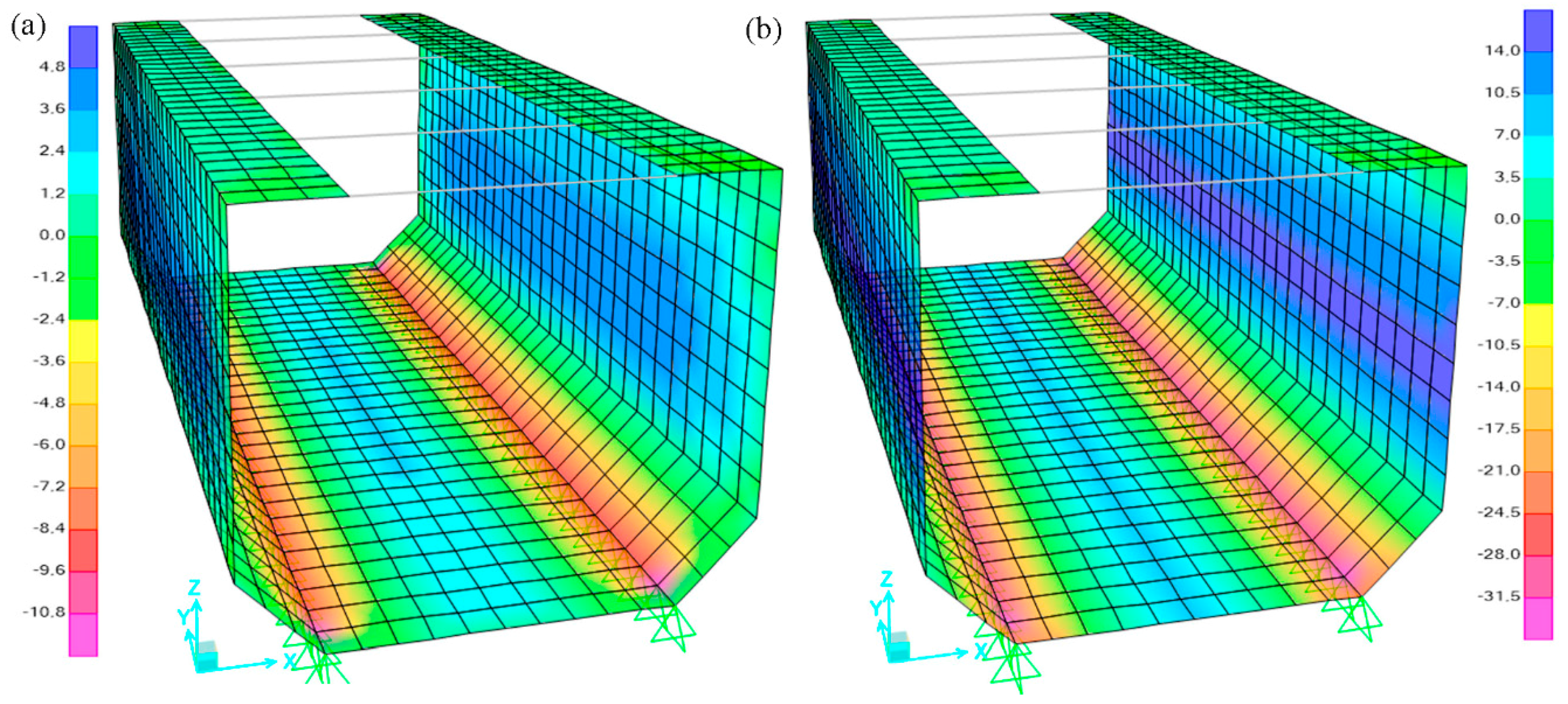
Regarding the service limit state of deformations,
Figure 6 gathers the displacements field for the load combination
C1. The maximum lateral (opening) displacement is 2.0 mm while the maximum upwards displacement of the bottom is 0.1 mm. Both magnitudes are considered to be structurally assumable and these do not lead to any esthetical concern since those would not be perceptible from the walkways or from a car-driver perspective. It is worth to note that the bottom tends to detach from the spandrel.
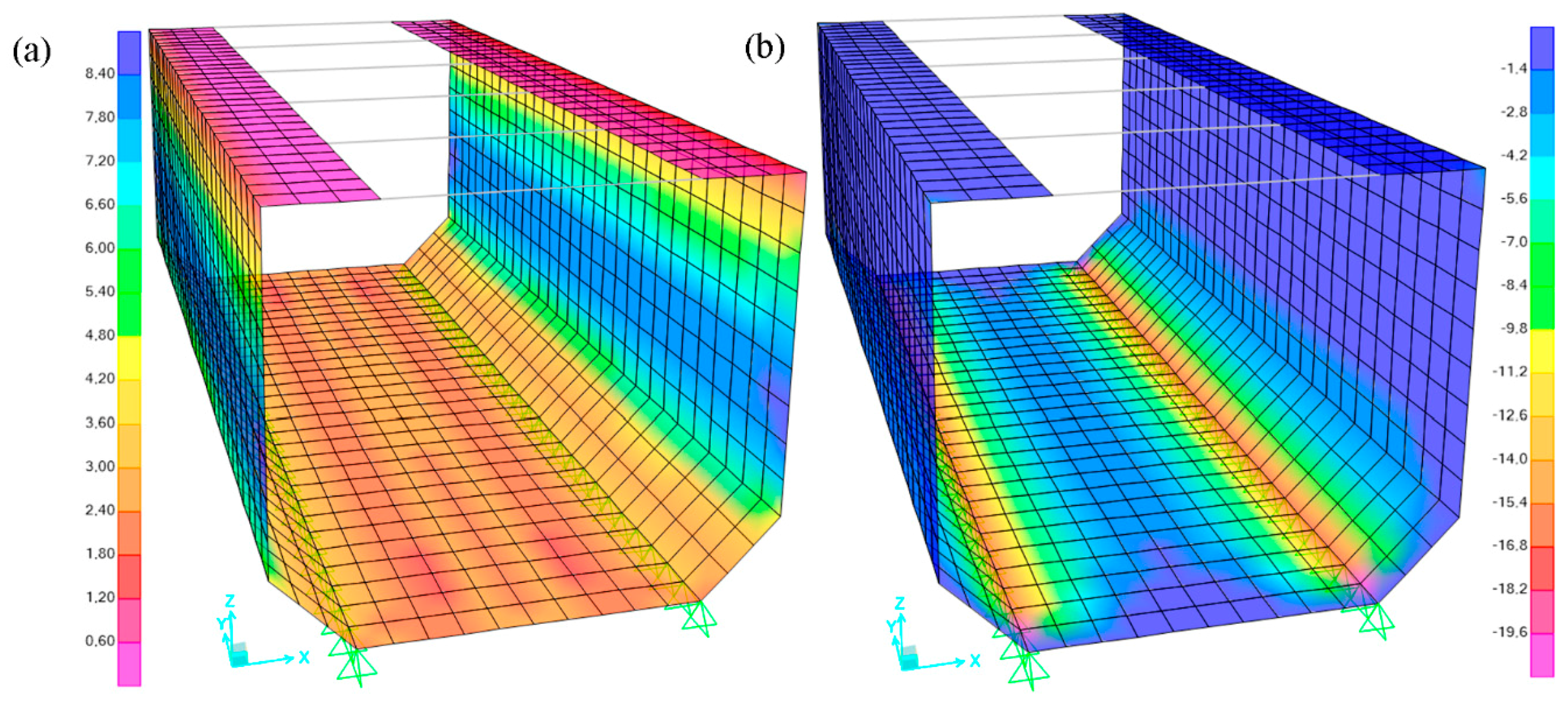
Regarding the cracking service limit state,
Figure 7 represents the
M11 (activate the secondary reinforcement, see
Figure 4) and
M22 (activate the main reinforcement) bending moment distributions for the load combination
C1. The characteristic crack width (
wk) is assessed by considering this combination and it has been confirmed that the limit state condition
wk = 0.10 mm <
wmax = 0.30 mm, where
wmax is the maximum crack width allowed for the environmental conditions to which the structure is subjected, would be fulfilled in the new operational conditions of the canal.
The results gathered in
Figure 7 highlight that peak values of
M22 up to 15.7 mkN/m are reached at the cashiers while values up to −32.8 mkN/m are expected at the chamfer-slab joint (control sections 2 and 4, respectively; see
Figure 5b). Likewise, it can be confirmed that the
M11 bending moments are lower in magnitude with respect to
M22 (about a 30% of
M22) and these respond to a secondary bending induced by the geometry and boundary conditions.
Table 1 gathers the number (
nΦ12) of 12 mm-diameter steel reinforcing bars (
Φ12), the steel reinforcing area (
As), the average cracking bending moment capacity (
Mcrm) and the
wk assessed for every control cross-section (
Figure 5b) when subjected to
M22. It can be confirmed that only control section 4 is expected to crack (
M22 ≥
Mcrm),
wk being inferior to 0.10 mm.
The braces are subjected to pure traction forces (T) since the connection to the walkways is solved with plastic hinges (no bending forces are transmitted). The maximum magnitude of T is 20.7 kN, the average cracking tensile force (Tcrm) being 102.4 kN (the average tensile strength, fctm, considered is 2.56 N/mm2). Consequently, the likelihood of cracking is low and no cracks are expected due to direct loads. Nevertheless, considering that the braces are critical elements for the safe and suitable structural performance of the hydraulic section under service conditions, these were considered as cracked for the cracking service limit state verifications. Even with this safe-side assumption, the value of wk expected to be reached during operational conditions is 0.12 and, thus, inferior to the 0.30 mm allowed for this structure to guarantee that the reinforcement will not suffer from corrosion.
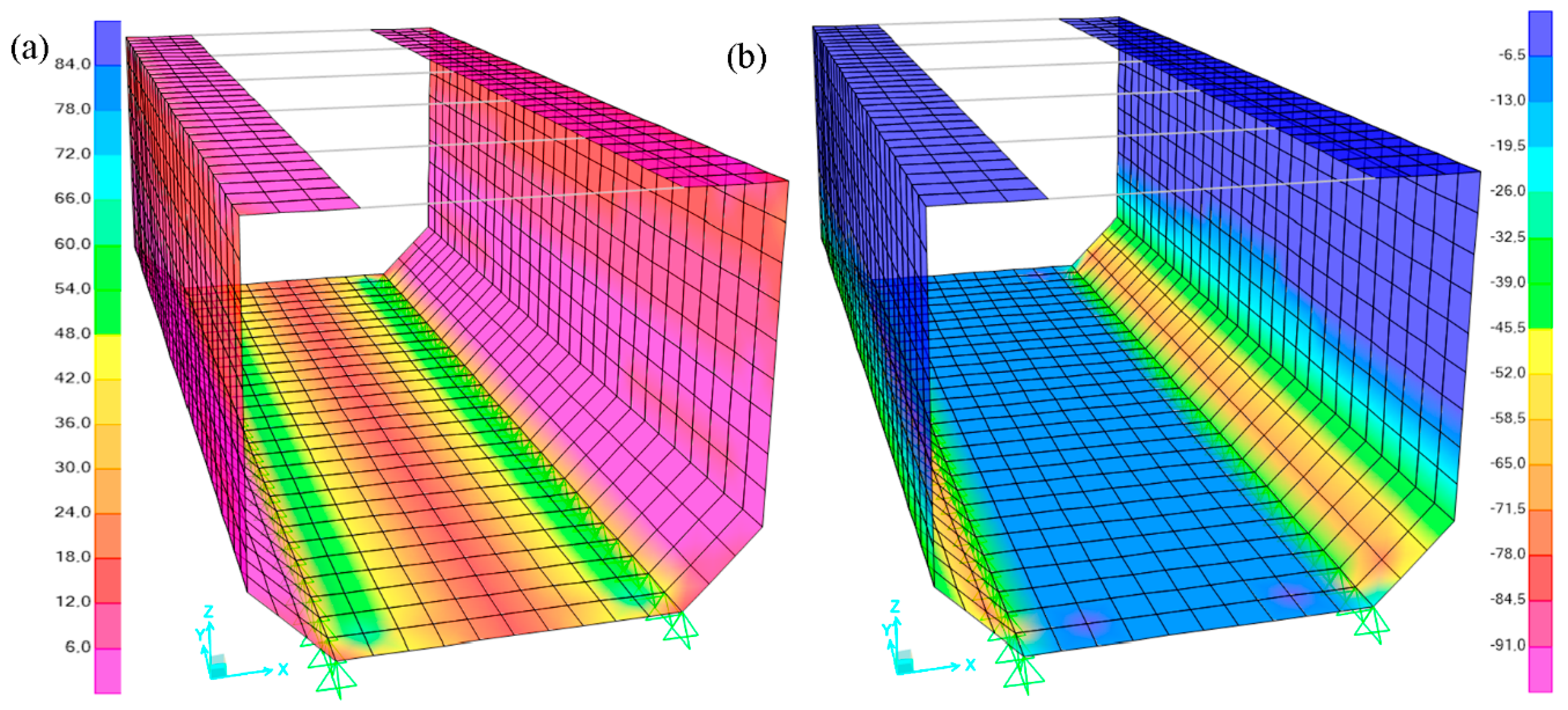
3.4. Ultimate Limit States
Figure 8 gathers the
M22 bending moment envelopes for the combination
C2 (
M22,d).
M11,d envelope is omitted since this is not determining for the reinforcement design; however, the pattern is similar (with different magnitudes) to that presented in
Figure 7a. For the accidental load combination (
C3), the bending moment envelopes’ pattern also respond to those presented in
Figure 8. In
Table 1 the ultimate limit state checks are reported.
The results gathered in
Table 1 confirm that the global safety factor against bending moment in ULS, defined as
SFu,M =
Mu/
Md is higher than 1.0 and, hence, the expanded hydraulic cross-section would be safe at structural level. Likewise, the braces are also safe in ULS since
SFu,T =
Tu/
Td is 2.0 and 1.1 for the load combinations
C2 and
C3, respectively.
Finally, the shear envelopes (
Vd) in ULS for the load combination C
2 are presented in
Figure 9. It must also be remarked that the envelopes follow the same pattern for the load combination
C3.
The global safety factor against a shear failure SFu,V = Vu/Vd is defined, Vu (=127.3 kN/m) being the shear strength of the cracked cross-section. The maximum values of Vd are 72.4 kN (C2) and 72.2 kN (C3) and, consequently, SFu,V > 1.00.
4. Conclusions
The structural analysis of both aqueducts using the safety format accepted into the Spanish Structural Concrete Code (EHE-08) it has been confirmed that the lateral cashiers can be increased up to 0.60 m. This will lead to an increase of 19.1% of the hydraulic capacity while keeping the total weight increase below 10%.
This type of analyses could serve as guide for future similar designs (in Spain there are several aqueducts requiring repairs and extensions of the hydraulic capacity with similar geometry and boundary conditions to that studied herein). It is also confirmed (as other researchers did in previous studies for other existing structures) that designs according to previous standards (before 1970) tend to be conservative; this allows for increasing the load regime accordingly without requiring additional reinforcement.
Author Contributions
Conceptualization, A.d.l.F., A.B., T.C.; Methodology, A.d.l.F., V.A., R.Q.; Software, A.d.l.F.; Validation, A.d.l.F., A.B.; Formal Analysis, A.d.l.F., R.Q.; Investigation, A.d.l.F., T.C., V.A.; Resources, A.d.l.F., V.A., T.C.; Data Curation, A.d.l.F., V.A.; Writing-Original Draft Preparation, A.d.l.F.; Writing-Review & Editing, A.d.l.F., A.B., V.A., T.C., R.Q.; Visualization, A.D.L.F., A.B.; Supervision, A.d.l.F., V.A.; Project Administration, A.d.l.F., V.A.; Funding Acquisition, R.Q.
Funding
This technical study was funded by the Comunidad de Regantes del Canal de Aragón y Cataluña (CAyC).
Acknowledgments
The authors acknowledge the support and contribution of Rafael Romeo (president of Confederación Hidrográfica del Ebro between 2008–2012) and Antonio Aguado (Professor at the Civil and Environmental Department of UPC).
Conflicts of Interest
The authors declare no conflict of interest.
References and Notes
- de los Ríos, F. Coll de Foix Aqueduct Project. Design and Construction Project, 1907. (In Spanish)
- Hué, F. Consolidation and covering of the Capdevila Aqueduct. Design and Construction Project, 1949. (In Spanish)
- Hué, F. Project for the increase of the hydraulic capacity of the Aragón and Catalonia Canal. Design and Construction Project, 1961. (In Spanish)
- de la Fuente, A.; Aguado, A. Hydraulic capacity increase for the Coll de Foix and Capdevila Aqueducts. Design and Construction Project, 2016. (In Spanish)
- SAP2000, version 16. SAP2000 Integrated Software for Structural Analysis and Design. Computers and Structures Inc.: Berkeley, CA, USA, 2016.
- CPH 2008. Structural Concrete Spanish Guide; Ministerio de Fomento: Madrid, Spain, 2008.
© 2018 by the authors. Licensee MDPI, Basel, Switzerland. This article is an open access article distributed under the terms and conditions of the Creative Commons Attribution (CC BY) license (http://creativecommons.org/licenses/by/4.0/).


