Article

Experimental Analysis of the Strengthening of Reinforced Concrete Beams in Shear Using Steel Plates

by
Marília M. Bez Batti
1,
Bruno do Vale Silva
2,
Ângela Costa Piccinini
1,*,
Daiane dos Santos Godinho
1 and
Elaine Guglielmi Pavei Antunes
1
1
Departamento de Engenharia Civil, Universidade do Extremo Sul Catarinense, Criciúma 88806-000, SC, Brazil
2
Departamento de Engenharia Civil, Faculdades Adamantinenses Integradas, Adamantina 17800-000, SP, Brazil
*
Author to whom correspondence should be addressed.
Submission received: 31 July 2018 / Revised: 6 November 2018 / Accepted: 13 November 2018 / Published: 16 November 2018
(This article belongs to the Special Issue Selected Papers from the REHABEND 2018 Congress)

Abstract

:
In some situations, it is necessary to strengthen or rehabilitate a structure in the short term, but before doing so, a critical analysis of the underlying causes is required to find the best technique to solve the problem. The structural strengthening is used to increase an element’s ability to resist a stress when it no longer meets the original conditions or new necessities of use due to faults, deterioration, thermal variations, and lack of maintenance. The present article aims to evaluate the strengthening of reinforced concrete beams with 0.75 mm thick SAE 1020 steel plates bonded with epoxy-based structural adhesive. The steel plates were attached to the sheared area before and after the beams were taken to the breaking point load. According to the results, it was possible to conclude the effectiveness of the strengthening applied to healthy beams that had its bearing capacity increased up to 50%. The beam that was strengthened after the shear, with a fissure that was restored with epoxy-based structural adhesive, had its load bearing capacity increased by 49.2%. The beams with fissures that were filled with mortar had their bearing capacity decreased by 58.70% if compared with the reference beams, and thus they presented an unsatisfactory performance.

1. Introduction

Since ancient times, mankind has been worried about ways to adapt its buildings to meet its needs. The development of new technologies is responsible for major transformations in the construction industry, but failures in some structures may lead to unsatisfactory results. According to some studies, De Souza et al. and Deghenhard [1,2], this set of factors is called structural deterioration and can present different causes: From “natural” aging of the structure to accidents and even irresponsibility of some professionals who choose to use materials that do not follow specifications, alleging, most of the time, budget reasons.
A relatively new branch has emerged in the field of civil engineering. This branch is the study of pathological manifestations in buildings, and, as the name suggests, it is responsible for investigating the origins, causes, manifestations, and consequences of problems that may arise in buildings [1]. In several situations, it is necessary to strengthen or rehabilitate structures in the short term, but it is necessary to analyze the causes of the damage to define the best techniques to recover the system. According to some studies Metha et al. and Pimenta [3,4], the structural strengthening is used to increase the structural element’s ability to resist a stress when it no longer meets the original conditions or new necessities of use due to design or design failures, alteration of a building’s function, natural deterioration, thermal variations in concrete, lack of maintenance, and other reasons.
Reinforcement can increase the strength of the structural part against bending and shear forces in addition to increasing stiffness and decreasing its deformability [5].
In the 1960s, researchers in France [6,7] began to test the structural strengthening of reinforced concrete beams using steel plates bonded with epoxy resin. These studies were based on the resistance properties of steel and the adhesion offered by epoxy resins [8].
When applied under normal conditions, this type of strengthening has a relatively low cost and a great efficiency level. However, there are some disadvantages, such as the resin’s low fire resistance and the high weight of the steel plates and its possibility of corrosion.
According to Pimenta [4], the reinforcement allows a monolithic bond between the steel plate and the concrete structure causing the reinforced structure to work under predicted stresses in calculation and thus to continue to work satisfactorily over time.
According to Appleton et al. [9], the strength of the steel used in the reinforcement should not be of very high strength, so high deformation is not required to mobilize its strength.
Higashi [5] states that in order to implement the reinforcement, the structure of all removable permanent and variable actions should be alleviated in order to ensure that the steel plates are mobilized for the service loads.
Moreover, according to Appleton et al. [9], the reinforcement project should include the sizing and an analytical evaluation of the effectiveness of the intervention, and, after the execution of the reinforcement, load tests must be performed for the service actions to prove the result of the intervention.
In addition to the advantages such as rapid execution, which, through a qualified professional, becomes the most cost-effective reinforcement of the market, there is also an insignificant increase in the section of reinforced concrete that may be coated by mortar after curing and thus rendering it imperceptible; the reinforcement allows a significant improvement of the resistant capacity (up to 50%); and intervention can occur without interruption of the use of the structure and through non-demolition of the structural elements [10].
Meier et al. and Täljsten [11,12] indicate that although steel is the most widely reported reinforcing material, it also has some significant drawbacks. Among them are the systems with high weight, making the manipulation and placement difficult; the corrosivity of the steel on the surface of the joint between the steel and the adhesive; and the need to create connecting joints between plates due to the limitations of the dimensions for their transport. In addition to the above disadvantages, Branco [10] reports on the sensitivity to atmospheric agents, which may cause glue deterioration with increasing temperatures and the possibility of displacement of the plate end if the execution had weaknesses.
Beams and slabs may have reinforcements to solve problems caused both by stresses due to the bending moment and stresses due to shear force. In the case of the action of the bending moment, the fault stems from the insufficiency of the tensile strength ratio causing fissures in the central region of the beam and can lead the piece to ruin, or from the insufficiency of the reinforcement in the compressed zone, the upper part of the beam. In the case of a deficiency in shear force, failures can occur due to a lack or misplacement of the transverse reinforcement [13].
Figure 1 presents the technique related to reinforcement with steel plates due to deficiencies in the shear force and indicates the two possibilities: The first with the steel plates and the epoxy resin and the second with the steel plates, epoxy resin, and the bushings expansive (Sousa [14] apud Higashi [5]).
There are several techniques for structural strengthening, but this study was based on the research developed by Almeida [15]. Thus, the objective of this experimental procedure was to analyze the load capacity of healthy beams and beams after rupture. The analysis took into consideration the structural strengthening with 0.75 mm thick SAE 1020 steel plates bonded with epoxy-based structural adhesive in the shear areas of the beams to stabilize or increase the beam shear resistance.

2. Materials and Methods

The experimental design of this work was divided into two phases. The first phase corresponded to a pilot of the four-point bending test with two beams. One beam contained three stirrups and a spacing of 90 cm, and the other beam contained six stirrups spaced 30 cm apart.
The second phase followed the manufacture of five standard beams containing six stirrups in each one spaced 30 cm apart. Two of these beams were used as reference and stressed to the breaking point, and maximum load, vertical displacements, and fissures were obtained. These two beams plus the pilot (ruptured in the previous phase of the work), called VR, had their fissures filled, two with mortar paste, called VRP-A, and the other with epoxy resin, called VRP-E. After that, they were strengthened with steel plates. The three remaining beams, called VRF, were strengthened in the shear area with 0.75 mm thick SAE 1020 steel plates bonded with epoxy resin.
The beams were made with cross-sections of 12 × 20 cm and a length of 190 cm containing 6 stirrups of 5 mm in diameter and a spacing of 30 cm. Theses beams did not meet the criteria in specification NBR 6118 [16] because the intention was to generate shear rupture. For the reinforcements, we used CA-50 steel and followed the criteria of NBR 6118 [16]. Thus, two steel bars of 10 mm diameter were used for flexural reinforcement totaling an area of 1.6 cm2 of steel. Figure 2 shows the details of the reinforcements in the beams. Figure 3 shows the five beams C25 (the class which represents the characteristic compressive strength of 25 MPa at 28 days) concreted. The concrete was made at Concretar Concreto Usinado, Araranguá-SC, Brazil and the concrete was densified with the aid of immersion vibrators.
The slump test was performed in the fresh-state following the recommendations of NBR 6118 [16], which established values of 10 ± 2 cm. The result for the concrete was 11 cm.
On the same day, fourteen cylindrical specimens (Ø 10 × 20 cm) were molded according to the specifications of NBR 5738 and NBR 5739 [17,18] to obtain the axial compressive strength of the concrete after 7, 14, 28, and 35 days. Diametrical compression and modulus of elasticity tests were performed at 28 days according to NBR 7722 and NBR 8522 [19,20].
After 28 days following the curing, the beams were unmolded and taken to an experimental structures laboratory (Laboratório Experimental de Estruturas (LEE) of Universidade do Extremo Sul Catarinense (UNESC)) for testing.
We used twenty 750 μm thick SAE 1020 steel plates, with dimensions of 5 × 20 cm (width × length) and a spacing of 5 cm between them. The plates were applied in the shear area on both faces of the beam. Figure 4 shows the application of the steel plates following the diagrams of the shear and bending moment of the beam.
For the bonding of the steel plates, an EP (epoxy) structural adhesive was used. It was a bautech® epoxy-based bi-component that was pre-dosed and presented the following characteristics: high adhesion, mechanical, and chemical resistance, impermeability to water and oil, total cure in 7 days, and initial hardness in 12 h. The application of the structural adhesive followed the manufacturer’s recommendations which specifies that the surface must be free from dust, release agents, or any substance that may impair the adhesion. In order to improve the adhesion before bonding, grooves were made in the steel plates and in the concrete beams with the aid of an N50 sandpaper. The epoxy-based structural adhesive was applied with a maximum thickness of 2.0 mm and with the aid of spatulas. Figure 5 shows the application of the structural adhesive on the steel plates, the bonding process, and the concrete beam after the bonding.
The beams were moved 35 days after concreting and met the minimum requirement of 24 h without moving them after the bonding of steel plates and 7 days before releasing of the load. For the four-point bending test, we used a steel reaction frame with a hydraulic cylinder and a load cell with a maximum reading capacity of 500 kN attached to its base. To measure the beam deflection, a displacement transducer (Linear Variable Differential Transformer—LVDT) with a maximum reading of 100 mm was located in the center of the beam. These devices were connected to the Quantum X® data acquisition system that used Catman Easy® software, both from HBM®.

3. Results

Table 1 presents the results of resistance during the ages of curing executed by molding of specimens.
Table 2 presents the nomenclature used to represent the variables in the study.
By applying the load until the beams reached their breaking point, we have obtained the maximum displacement according to the regulation, which specifies that this value should be obtained from dividing its length by 250 (L/250). The reference beams (VR) had their rupture mode by shear at the breaking point with a maximum load average of 45.20 kN. The strengthened healthy beams, with steel plates, had their rupture mode by bending, showing that the strengthening behaved as expected.
Three beams with fissure filling after rupture, one beam with epoxy adhesive (VRP-E), and two with mortar (VRP-A), when subjected to the four-point flexural test again, presented very different shear ruptures. In VRP1-E, a new fissure was opened, and the beam supported a 67.44 kN load. However, VRP2-A and VRP3-A presented rupture in the same fissure that was opened in the first test and supported an average of 28.58 kN.
Figure 6 presents the load versus displacement curves during the bending test.
Table 3 presents the analysis of the results for each beam and its maximum displacement compared to the load obtained in the maximum displacement as specified by the regulation (L/250).
Each beam group showed different behaviors. The reference beams (VR1, VR2, and VR3) obtained rupture values on the shear area, while the strengthened healthy beams, i.e., those reinforced with steel plates (VRF1, VRF2, and VRF3), obtained rupture values in the bending area, and the beams that were strengthened after the rupture obtained rupture values on the shear area.
Figure 7 presents the reference beams after the test.
Figure 8, Figure 9 and Figure 10 present the healthy beams strengthened with steel plates after the test.
Figure 11 presents the results of the beams, called VRP-E and VRP-A, that had the fissures filled and were reinforced with steel plates after rupture.

4. Conclusions

The beams considered as reference (VR) had their mode of shear rupture. It was observed that the strengthened healthy beams obtained satisfactory results and had their load bearing capacity increased by 50% compared to the reference beams, which was in accordance to expectations and to Branco [10].
The strengthened beam that had its fissure filled with structural adhesive (VRP-E) presented an increase of 49.20% in its load bearing capacity in relation to the reference beams. However, the beams that had their fissures filled with mortar (VRP-A), presented a decrease of 58.70% in their bearing capacity in relation to the reference beams and thus presenting an unsatisfactory performance.
The epoxy-based structural adhesive was not difficult to apply, since we have followed the manufacturer’s specifications for bonding 0.75 mm thick SAE 1020 steel plates. This strengthening contributed to an increase in the resistance of the beams subjected to the four-point bending test.
Finally, if one applies steel plates to healthy or broken beams and fills their fissures with epoxy structural adhesive, the strengthening offers great efficiency and increases their bearing capacity.
For future work, we suggest a reduction in the spacing between the stirrups to verify the rupture in the shear area. We also suggest the reduction of the quantity of 0.75 mm thick SAE 1020 steel plates in the shear area to verify their performance.

Author Contributions

Conceptualization, Â.C.P., B.d.V.S., and D.d.S.G.; methodology, M.M.B.B., E.G.P.A., and B.d.V.S.; formal analysis, Â.C.P. and D.d.S.G.; investigation, M.M.B.B. and B.d.V.S.

Funding

This research received no external funding.

Conflicts of Interest

The authors declare no conflict of interest.

References

  1. De souza, V.C.M.; Ripper, T. Patologia, Recuperação e Reforço de Estruturas de Concreto; Editora Pini Ltd.: São Paulo, Brazil, 1998; 255p. [Google Scholar]
  2. Deghenhard, C.C. Análise Experimental da Capacidade Portante em Vigas de Concreto Armado Sujeitas a Flexão com Reforço Metálico Colado na Face Tracionada; Universidade do Extremo Sul Catarinense: Criciúma, Brazil, 2013; 19p. [Google Scholar]
  3. Metha, P.K.; Monteiro, P.J.M. Concreto: Microestrutura, Propriedades e Materiais; IBRACON: São Paulo, Brazil, 2008; 674p. [Google Scholar]
  4. Pimenta, T.M. Comportamento Estrutural de Vigas de Concreto Armado Reforçadas com Chapas Metálicas, Coladas com Geopolímero, e com Mantas de Sisal Coladas com Resina Epóxi; Curso de Engenharia Civil, Universidade do Extremo Sul Catarinense: Paraíba, Brazil, 2012; 65p. [Google Scholar]
  5. Higashi, M.M.Y. Reforço em Estruturas de Betão Armado com Chapas de Aço. Master’s Thesis, Instituto Superior de Engenharia do Porto, ISEP, Porto, Portugal, November 2016. [Google Scholar]
  6. L’hermite, R. L’application des Colles et Resines dans la Construction; La beton a Coffrage Portant, Annales l’Institut Technique: Paris, France, 1967; Volume 239. [Google Scholar]
  7. Bresson, J. Nouvelles Recherches et Applications Concernant l′Utilisation des Collages dans les Structures; Beton Plaque Annales de l’Institut Tecnique du Batiment et Travaux Publics; Annales l’Institut Technique: Paris, France, 1971; Volume 278. [Google Scholar]
  8. Juvandes, L.F.P. Reforço e Reabilitação de Estruturas de Betão Usando Materiais Compósitos de “CFRP”. Ph.D. Thesis, Departamento de Engenharia Civil, Universidade do Porto, Porto, Portugal, 1999. [Google Scholar]
  9. Appleton, J.; Gomes, A. Reforço de Estruturas de Betão Armado por Adição de Armaduras Exteriores; Revista Portuguesa de Engenharia de Estruturas (RPEE): Lisboa, Portugal, 1997; pp. 1–18. [Google Scholar]
  10. Branco, F.G. Reabilitação e Reforço de Estruturas; Instituto Superior Técnico: Lisboa, Portugal, 2012. [Google Scholar]
  11. Meier, U. Repair Using Advanced Composites. In Proceedings of the International Conference of Composite Construction—Conventional and Innovative (IABSE), Innsbruck, Austria, 16–18 September 1997; pp. 113–124. [Google Scholar]
  12. Täljsten, B. Plate Bonding-Strengthening of Existing Concrete Structures with Epoxy Bonded Plates of Steel or Fiber Reinforced Plastics. Ph.D. Thesis, Division of Structural Engineering, Lulea University of Technology, Lulea, Sweden, 1994; 237p. [Google Scholar]
  13. Reis, A.P.A. Reforço de Vigas de Concreto Armado por meio de Barras de aço Adicionais ou Chapas de aço e Argamassa de alto Desempenho. Ph.D. Thesis, Escola de Engenharia de São Carlos, São Carlos, Brazil, 1998. [Google Scholar]
  14. Sousa, A.F.V. Reparação, Reabilitação e Reforço de Estruturas de Betão Armado. Ph.D. Thesis, Faculdade de Engenharia da Universidade do Porto, Porto, Portugal, 2008. [Google Scholar]
  15. Almeida, J.M.A. Vigas de Concreto Armado Reforçadas ao Cisalhamento com Elementos Compósitos com Fibras de Vidro; Jornadas Sul Americanas de Engenharia Estrutural, ASAEE (Associação Sul Americana de Engenharia Estrutural): Rio de Janeiro, Brazil, 2012; 14p. [Google Scholar]
  16. Associação Brasileira de Normas Técnicas. NBR 6118: Projeto de Estruturas de Concreto; Associação Brasileira de Normas Técnicas: Rio de Janeiro, Brazil, 2014. [Google Scholar]
  17. Associação Brasileira de Normas Técnicas. NBR 5738: Concreto—Procedimento para Moldagem e Cura de Corpos-de-Prova; Associação Brasileira de Normas Técnicas: Rio de Janeiro, Brazil, 2003. [Google Scholar]
  18. Associação Brasileira de Normas Técnicas. NBR 5739: Concreto—Ensaio de Compressão de Corpos de Prova Cilíndricos; Associação Brasileira de Normas Técnicas: Rio de Janeiro, Brazil, 2007. [Google Scholar]
  19. Associação Brasileira de Normas Técnicas. NBR 7222: Concreto e Argamassa–Determinação da Resistência a Tração por Compressão Diametral de Corpos de Prova Cilíndricos; Associação Brasileira de Normas Técnicas: Rio de Janeiro, Brazil, 2011. [Google Scholar]
  20. Associação Brasileira de Normas Técnicas. NBR 8522: Concreto—Determinação do Módulo Estático de Elasticidade à Compressão; Associação Brasileira de Normas Técnicas: Rio de Janeiro, Brazil, 2008. [Google Scholar]
Figure 1. Strengthening with steel plates due to shear force with and without bushes, respectively. 1 = steel plate; 2 = resin; 3 = bushing; ts = plate thickness; tg = epoxy resin thickness; hs = plate height; Sousa [14] apud Higashi [5].
Infrastructures 03 00052 g001
Figure 2. Details of the reinforcements in beams.
Infrastructures 03 00052 g002
Figure 3. Beams after concreting.
Infrastructures 03 00052 g003
Figure 4. Scheme of the application of steel plates versus the shear diagram and versus the bending moment diagram.
Infrastructures 03 00052 g004
Figure 5. Beam strengthening. (a) Application of the structural adhesive. (b) Concrete beam after bonding.
Infrastructures 03 00052 g005
Figure 6. Load diagram versus displacement.
Infrastructures 03 00052 g006
Figure 7. Reference beams after the test: (a) VR1; (b) VR2; and (c) VR3.
Infrastructures 03 00052 g007
Figure 8. Beam VRF1 after the test. (a) Beam overview. (b) Fissure details.
Infrastructures 03 00052 g008
Figure 9. Beam VRF2 after the test. (a) Beam overview. (b) Fissure details.
Infrastructures 03 00052 g009
Figure 10. Beam VRF3 after the test. (a) Beam overview. (b) Fissure details.
Infrastructures 03 00052 g010
Figure 11. Strengthened beams after the test: (a) VRP1-E; (b) VRP2-A; and (c) VRP3-A.
Infrastructures 03 00052 g011
Table 1. Results of resistance gain control tests over age.
Age (Days)Compression Resistance (MPa)Tensile Strength by Diametral Compression (MPa)Modulus of Elasticity (MPa)
715.9--
716.5--
715.1--
Average (standard deviation)15.8 (0.7)
1419.3--
1419.7--
1418.7--
Average (standard deviation)19.2 (0.5)
2822.93.0335.5
2825.32.8736.7
2823.93.0234.8
Average (standard deviation)24.0 (1.2)2.97 (0.09)35.7 (0.9)
3526.7--
3528.7--
Average (standard deviation)27.7 (1.4)
Table 2. Nomenclature used for each type of beam.
NomenclatureDescription
VRReference Beam
VRFStrengthened Healthy Beam
VRP-EBeam strengthened after the shear (fissure filling with epoxy-based structural adhesive)
VRP-ABeam strengthened after the shear (fissure filling with Mortar AC III)
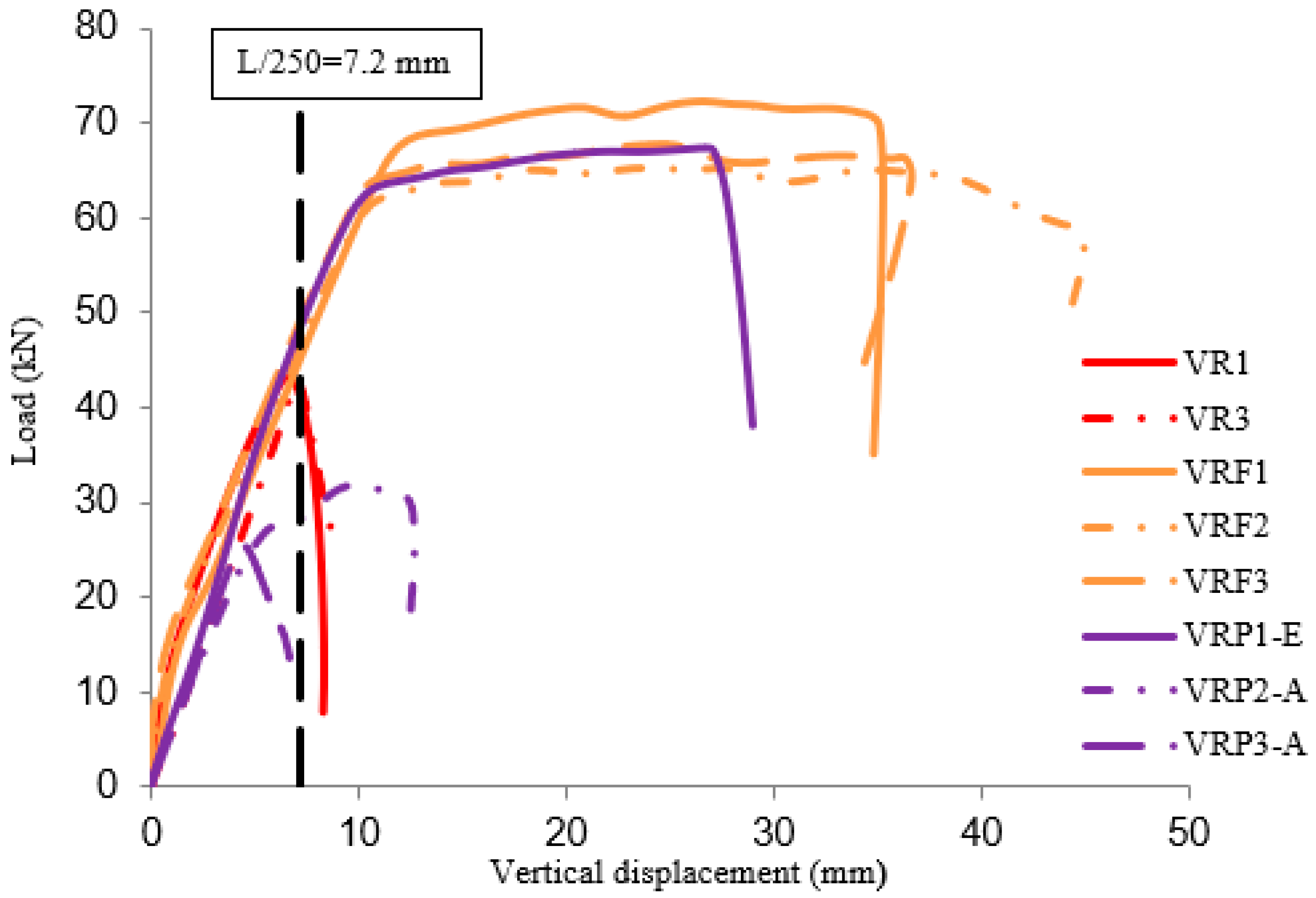
Table 3. Results of maximum displacement and load in the maximum displacement (according to the specification).
NomenclatureL/250—Displacement 7.2 mmRupture
Load (kN)ReadingLoad (kN)Displacement (mm)
VR141.5After the rupture43.26.5
VR2 *--51.2-
VR343.1After the rupture41.27.4
Average (standard deviation)42.3 (1.1) 45.2 (5.3)6.9 (0.6)
VRF145.5Before the rupture71.720.3
VRF246.7Before the rupture65.218.3
VRF350.3Before the rupture66.733.3
Average (standard deviation D.P.)47.5 (2.5) 67.8 (3.4)24.0 (8.1)
VRP1-e48.3-67.426.2
VRP2-a28.2Before the rupture31.89.8
VRP3-a-Before the rupture25.44.5
Average (standard deviation D.P.)38.2 (14.2) 41.5 (22.7)13.5 (11.3)
* In VR2, it was not possible to get the displacement reading due to an equipment failure.

