Polymer Concrete for Bridge Deck Closure Joints in Accelerated Bridge Construction


1
Department of Civil and Environmental Engineering, Florida International University, Miami, FL 33174, USA
2
Department of Civil, Construction and Environmental Engineering, University of New Mexico, Albuquerque, NM 87131-0001, USA
*
Author to whom correspondence should be addressed.
Infrastructures 2019, 4(2), 31; https://0-doi-org.brum.beds.ac.uk/10.3390/infrastructures4020031
Submission received: 12 May 2019
/
Revised: 28 May 2019
/
Accepted: 28 May 2019
/
Published: 1 June 2019
(This article belongs to the Special Issue Advanced Materials and Technology for Resilient Bridge Infrastructures)
Abstract
:Prefabricated concrete bridge deck panels are utilized in Accelerated Bridge Construction (ABC) to simplify bridge deck construction. Concrete with good bond and shear strength as well as excellent flowability is required to fill bridge deck closure joints. This paper discusses the use of polymer concrete (PC) for bridge deck closure joints in ABC. PC produced using poly methyl methacrylate and standard aggregate was tested. Test results of PC are compared to Ultra-High Performance Concrete (UHPC). Development length, lap splice length and shear strength of unreinforced PC were tested. It is shown that PC has a development length of 3.6 to 4.1 times the reinforcing bar diameter that is close to one-half the development length of 6 to 8 times the bar diameter required with UHPC. PC also showed a shorter splice length compared with that reported for UHPC. Finally, unreinforced PC showed shear strength that is twice that of UHPC. It is evident that using PC in bridge deck closure joints in ABC can improve constructability and provide cost-savings and eliminate reinforcing bar congestion.
1. Introduction
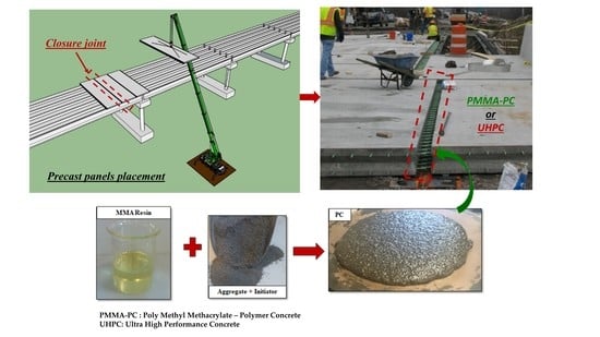
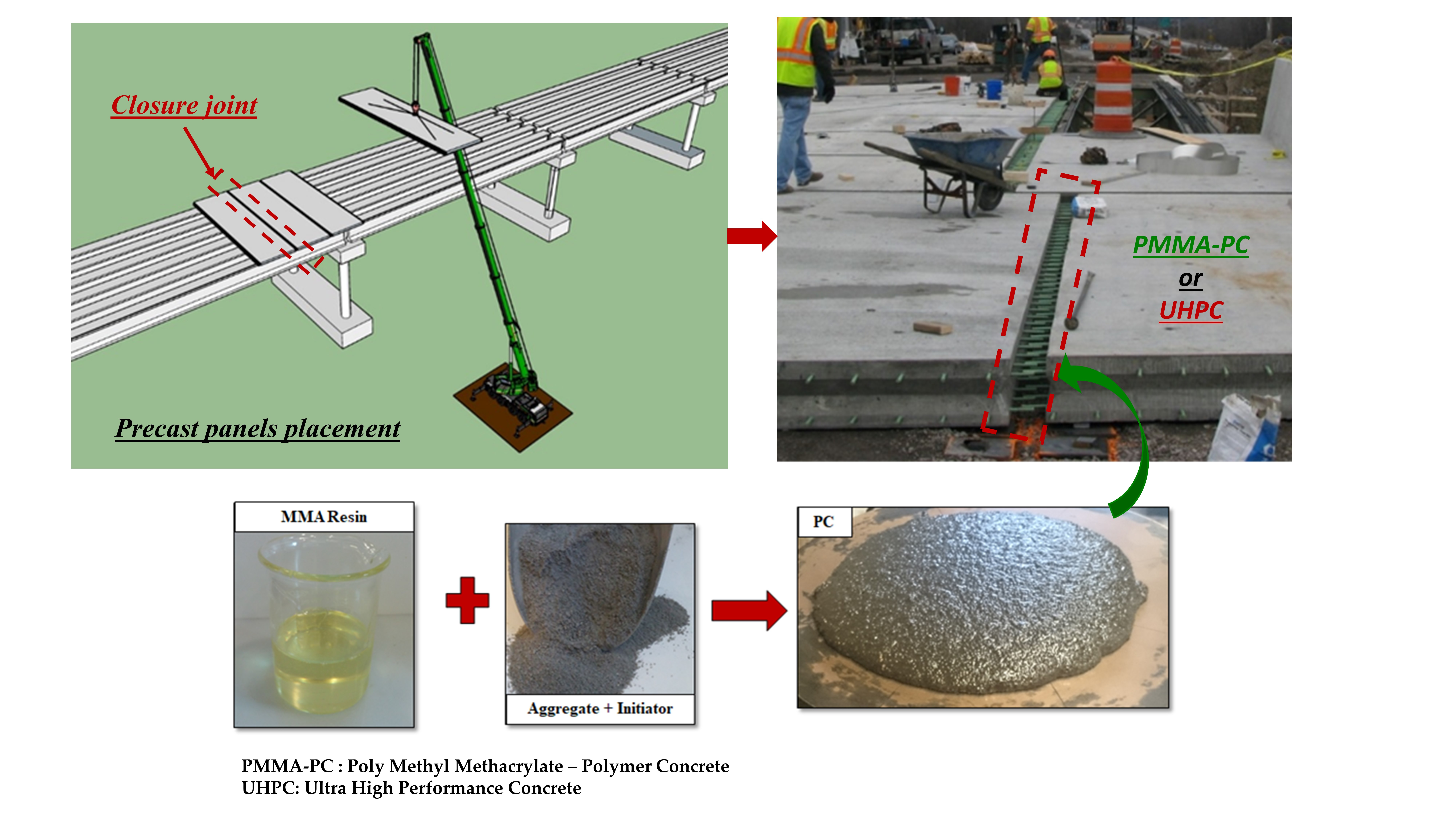
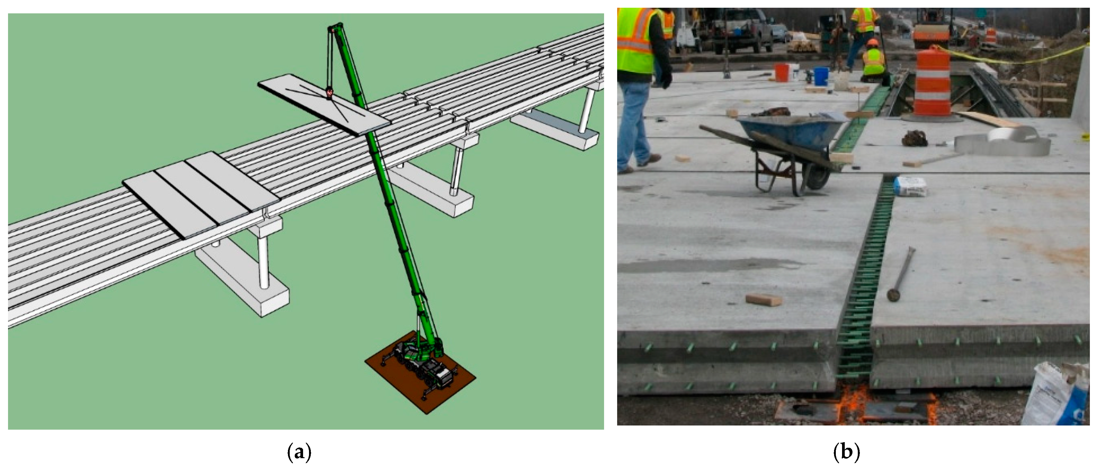
Accelerated bridge construction (ABC) techniques have become more common worldwide to meet the growing construction demand and the need to shorten construction time. ABC techniques enable optimizing construction schedule, increasing construction quality, and reducing onsite fatalities and injuries by eliminating major construction activities [1]. Typically, prefabricated bridge elements are cast in a controlled environment and shipped to the bridge location. The use of ABC techniques for superstructure requires developing special materials to fill in-situ closure joints between precast deck panels typically used ABC technique. A major challenge in closure joints is the inadequate development of the steel reinforcing bars which are spliced at the closure joint between two adjacent panels. The required development length for steel bars embedded in normal concrete common compressive strength is at least 24 times the steel bar diameter according to American Concrete Institute (ACI) [2] or at least 18 times the steel bar diameter according to American Association of State Highway and Transportation Officials (AASHTO) [3]. Therefore, cast-in-place concrete with a relatively high bond strength to prefabricated concrete surface and steel reinforcing bars is required. Researchers have suggested using Ultra-High Performance Concrete (UHPC) for its high performance including high bond strength with steel reinforcing bars and much-improved durability compared with normal concrete [4,5,6]. To consider concrete as UHPC, the concrete should achieve at least 124 MPa compressive strength. This high strength in UHPC is achieved by using a high cement content, low water/cement ratio less than 0.2, silica fume and well-graded materials [7,8]. Though UHPC under fresh state is workable and can be cast easily, it loses its workability quickly after mixing and curing conditions play an important role in achieving target UHPC properties. Furthermore, proper care is necessary to avoid shrinkage cracks in UHPC [9]. Considering, the above reasons, the field application of UHPC presents a true challenge because of the many requirements in mixing, placing, and curing of UHPC that are necessary to avoid cracking. Moreover, UHPC as proprietary material has a relatively high cost compared with all other types of concrete. Nevertheless, today more than 30 bridges have been constructed in the United States with bridge deck closure joints using UHPC [6]. Examples of UHPC connections were used in a set of bridges constructed on I-81 in Syracuse, NY, a bridge on County Road 47 (CR47) over Trout Brook near Stockholm, NY, and a bridge on U.S. Route 30 over the Burnt River and the Union Pacific Railroad near Huntington, OR [6]. Figure 1 shows schematic and construction of closure joints between two adjacent full-depth precast deck panels in ABC.
In polymer concrete, a cementitious binder is replaced by a polymeric one, such as epoxy, polyester, vinyl ester or other types of polymers [10]. Polymers are known for their significantly higher bond strength to many surfaces compared with any cementitious binders. Polymer concrete (PC) is therefore favorable when a strong bond to the existing concrete surface and/or reinforcement is required. PC produces a higher adhesion and durability properties compared with any Portland cement concrete (PCC). The compressive strength of PC can range between 20.7 MPa to 124 MPa, the tensile strength of PC may reach up to 13.8 MPa, high shear strength up to 20.7 MPa, flexural strengths up to a 41.4 MPa. Using Isophthalic polyester, PC of 96.5 MPa compressive strength has been reported [11,12]. A 2.8 MPa bond strength was reported in the literature for PC produced using low viscosity silane modified vinyl ester mortar [13]. Researchers also indicated that PC overlays showed no delamination with the substrate PCC beams after 2 million cycles of fatigue loading [14]. Moreover, PC is corrosion resistant; has very good cracking resistance, and showed superior durability [10] thus it is a good alternative material for bridge deck closure joints. These properties make PC a favorable material for bridge deck overlays [15]. For bridge deck closures, the design is governed by the development length, lap splice length of steel in the substrate material and the shear strength of the substrate material itself.
This paper investigates the potential use of poly methyl methacrylate (PMMA) polymer concrete denoted here as PMMA-PC as a filling material for ABC closure joints. The low viscosity of PMMA, ease of mixing, and relatively high workability of PMMA-PC are key features for its use for ABC closure joints. Here, the minimum development length of steel reinforcement when spliced in PMMA-PC, lap splice length between bars inside PMMA-PC, and shear strength are determined and compared with those of UHPC reported in the literature.
2. Material and Methods
Closure joints are typically cast where reinforcing bars are spliced at the bridge longitudinal direction. The main function of this reinforcement is to resist shrinkage of the bridge deck and cracking, therefore, steel reinforcing bars in sizes #13 (12.7 mm diameter) and #16 (15.9 mm diameter) that are typically used for longitudinal bars in construction. In order to explore the use of PMMA-PC in closure joints between full-depth precast deck panels, these bar sizes were tested to define the required development length and lap splice length for use in closure joints for ABC applications. Furthermore, shear strength of PC was also determined.
2.1. Materials
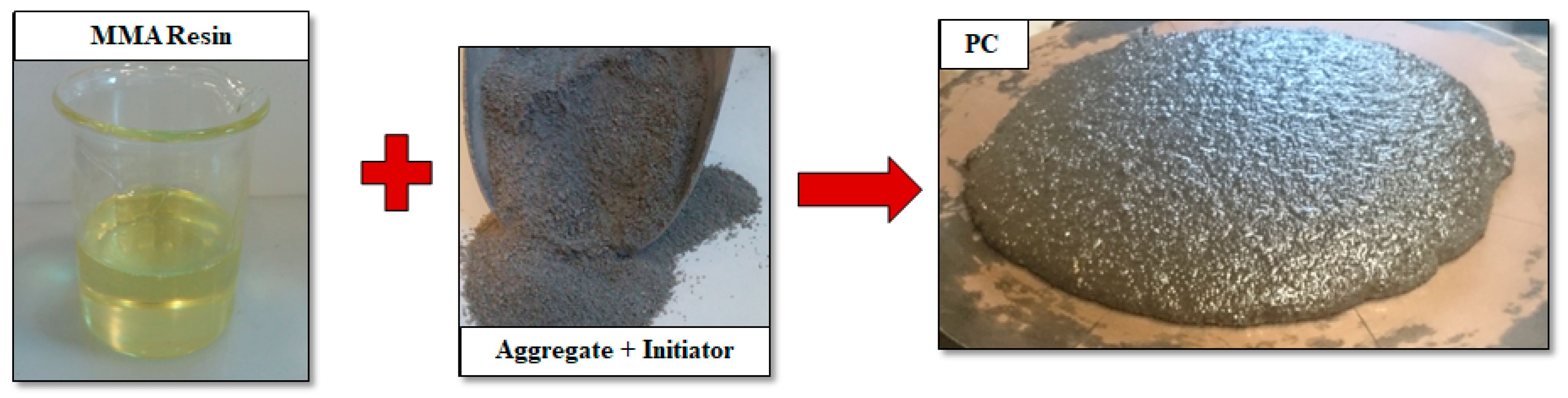
Figure 2 shows the material used in mixing PMMA-PC. PMMA-PC was produced by mixing methyl methacrylate resin with Benzoyl Peroxide initiator and well-graded aggregate of 19-mm nominal maximum size. PMMA-PC was mixed using a rotary drum mixer following technical data sheet provided by the supplier. The concrete was cast in the molds and vibrated to eliminate any cavities in the specimens that could affect the results. PMMA-PC was mixed and then left to be cured for one week in a standard temperature of 22 °C to reach its design strength. Three standard cylinder specimens were cast to determine the compressive strength following [16], in addition to the other three specimens to determine the tensile strength following [17]. Table 1 and Table 2 provide the mixture proportion of PMMA-PC and UHPC respectively.
2.2. Pull-Out Test
Figure 3a shows the test setup for the pull-out test to determine the minimum development length required for bars sizes #13 (12.7 mm) and #16 (15.9 mm), uncoated ASTM A572 Grade 60 in PMMA-PC. The pull-out test was guided by the FHWA report on bond behavior of reinforcing steel in UHPC [18]. The embedment length was determined as a multiplier of the reinforcing bar diameter (db). Pull-out tests were conducted for a total of four embedment lengths of 4db, 6db, 8db, and 10db. Three repetitions for each embedment length were tested for each bar size (3 repetitions × 4 embedment lengths × 2 bars sizes = 24 tested specimens). Pull-out specimens were tested at 7 days of age. The steel bar was pulled out from the concrete cylinders with a loading rate of 1.0 mm/min using Instron Universal Testing Machine with maximum capacity of 530 kN, resolution of 1 ± 0.01 N. The load and displacement were recorded continually with a sampling rate of 1 Hz.
2.3. Lap Splice Test
The minimum lap splice length of the steel bars was determined as a multiplier of the rebar diameter using a 4-point bending test for #13 (12.7 mm) reinforcing bars guided by Esfahani and Rangan [19]. The minimum lap splice length was calculated as the minimum bar overlap length to provide enough force transfer between the lapped bars to be controlled by concrete crushing failure instead of rebar slippage failure. Figure 3b shows the test setup of 660.4 mm beam span specimen loaded using two point loads at 152.4 mm spacing. The beam is 152.4 mm wide and 152.4 mm deep with a total length of 762 mm and reinforcing bar cover was 3db.
The tested splice lengths ranged from 1db to 7db with 1db interval (total of 7 lap splice lengths) in addition to a control beam with straight bars (Specimen C) and an unreinforced beam (total of 9 different details). Three repetitions were tested for each different detail (3 repetitions × 9 different details = 27 tested specimens). The 27 beam specimens were tested using the 4-point bending test setup at 7 days of age. The beams were loaded with a loading rate of 1.0 mm/min using Tinius Olsen Universal Testing Machine with maximum capacity of 1780 kN, resolution of 4.4 ± 0.04 N. Strain gauges were attached to steel bars and the top concrete fibers to record steel tensile and concrete compressive strains. The load, displacement, and strains were recorded continually with a sampling rate of 10 Hz.
2.4. Shear Test
A common practice is to use the same material for closure joints between full-depth precast deck panels and between the panels and the top of superstructure girders of either prestressed concrete girders or steel girders. Shear strength test was conducted to ensure that PMMA-PC has sufficient shear capacity to provide proper shear transfer and sufficient horizontal shear resistance at haunches between the superstructure girders and precast panels. The shear strength was determined using a modified 4-point test setup guided by Shuraim [20]. The beams were with a loading rate of 1.0 mm/min using Tinius Olsen Universal Testing Machine with maximum capacity of 1780 kN, resolution of 4.4 ± 0.04 N. The load and displacement were recorded continually with a sampling rate of 1.0 Hz. The shear strength was calculated for PMMA-PC, UHPC, and normal concrete (NC). The experimental shear strengths are compared with AASHTO prediction for shear strength [3]. Five repetitions for each concrete type were tested (5 repetitions × 3 concrete types = 15 tested specimens) following the test setup shown in Figure 3c. All PMMA-PC specimens were cured in ambient temperature for the 7-day period. All NC and UHPC specimens were cured at 52°C ± 2°C with 100% relative humidity to ensure complete curing.
The specimens were then allowed to dry for 24 h prior to testing. Load and displacement were acquired at a sampling rate of 10 Hz. Shear beams were tested under displacement-controlled protocol at 1.0 mm/min. The experimental shear strength has been calculated using Equation (1).
where, τ: is shear strength of concrete, P: is the failure load for beams, b: is width of the beam cross-section, d: is depth of the beam cross-section. The experimental shear strength of PMMA-PC, UHPC, and NC are compared with AASHTO shear strength of concrete from Equation (2) [3].
where, τAASHTO: is AASHTO shear strength of concrete, fc’: is the characteristic compressive strength of concrete, and β = 2 for non-prestressed concrete elements.
3. Experimental Results
Table 1 provides the main mechanical properties of PMMA-PC. PMMA-PC showed a compressive strength and split tensile strength of 72.6 ± 2.1 MPa and 6.6 ± 0.6 MPa respectively.
3.1. Pull-Out Test Results
All specimens with an embedment length of 4db failed due to debonding of steel rebar from PMMA-PC as shown in Figure 4a. For 6db specimens, the failure occurred either due to rebar breaking or debonding between the rebar and PMMA-PC after yielding of the rebar as shown in Figure 4b,c. For specimens with 8db and 10db, the failure in all specimens was due to rupture of the rebar as shown in Figure 4d.
For specimens with #13 reinforcing bars, all specimens with an embedment length of 4db failed in bond between the steel bar and PMMA-PC. For specimens with an embedment length of 6db, the failure occurred either due to steel bar rupture or due to failure in bond between the steel bar and PMMA-PC after yielding of the bar. For specimens with an embedment length 8db and 10db, failure in all specimens was due to steel bar rupture. All observed failure modes are shown in Figure 4.
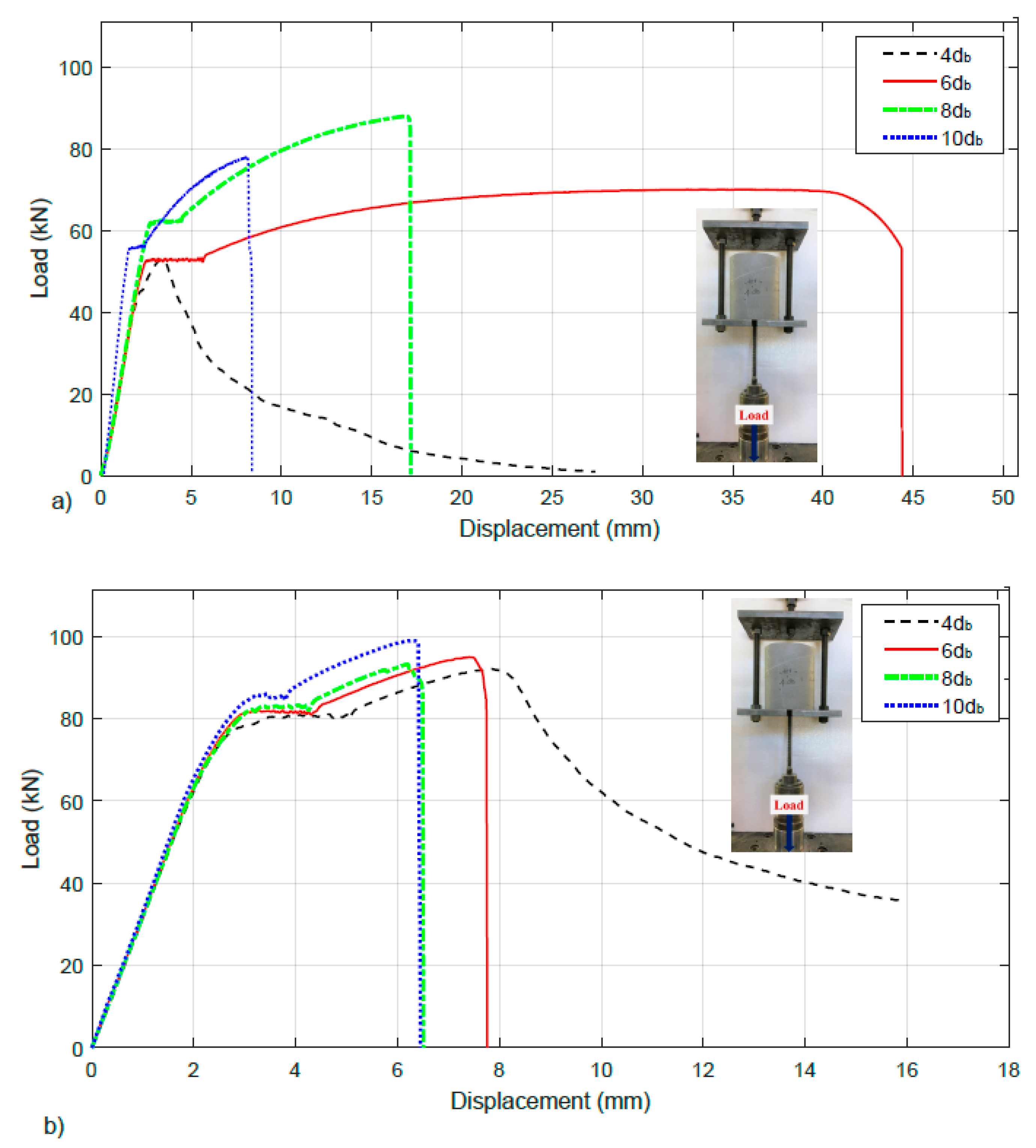
A median load-displacement curve for each embedment length is shown in Figure 5a as a reprehensive sample. The average load at failure (average peak load) and stress in rebar at failure of specimens with an embedment length of 4db, 6db, 8db, and 10db are listed in Table 3. The load at failure and stress in rebar at failure for each embedment length are shown in Figure 6a,b respectively compared with the values obtained from pull-out testing of bar #16. For specimens with #16 reinforcing bars, all specimens with an embedment length of 4db failed in bond between steel rebar from PMMA-PC after yielding of the bar. For specimens with an embedment length 6db, 8db and 10db, failure occurred due to steel bar rupture after passing the yield strength.
A median load-displacement curve for each embedment length is shown in Figure 5b, as a representative sample. The average load at failure (average peak load) and stress in rebar at failure of specimens with an embedment length of 4db, 6db, 8db, and 10db are listed in Table 3. The load at failure and stress in rebar at failure for each embedment length are shown in Figure 6a,b, respectively, compared with the values obtained from pull-out testing of bar #13.
The average bond strength between the steel bars and PMMA-PC was calculated from the specimens failed in bond as a mode of failure. The bond strengths for #13 and #16 reinforcing bars were estimated as 25.3 ± 0.9 MPa and 36.7 ± 0.4 MPa respectively. The development length of the rebar was determined using Equation (3).
where, ld is the development length (mm), fy is the yield strength of steel (413.7 MPa), db is the rebar diameter [mm], and fd is bond strength between concrete and steel (MPa). The minimum development length required for the steel bars to achieve yield strength was found to be 3.6db and 4.1db for #13 (12.7 mm) and #16 (15.9 mm) steel bars respectively. Figure 6c shows bond stresses for each embedment length for both #13 (12.7 mm) and #16 (15.9 mm) reinforcing bars.
3.2. Lap Splice Test Results
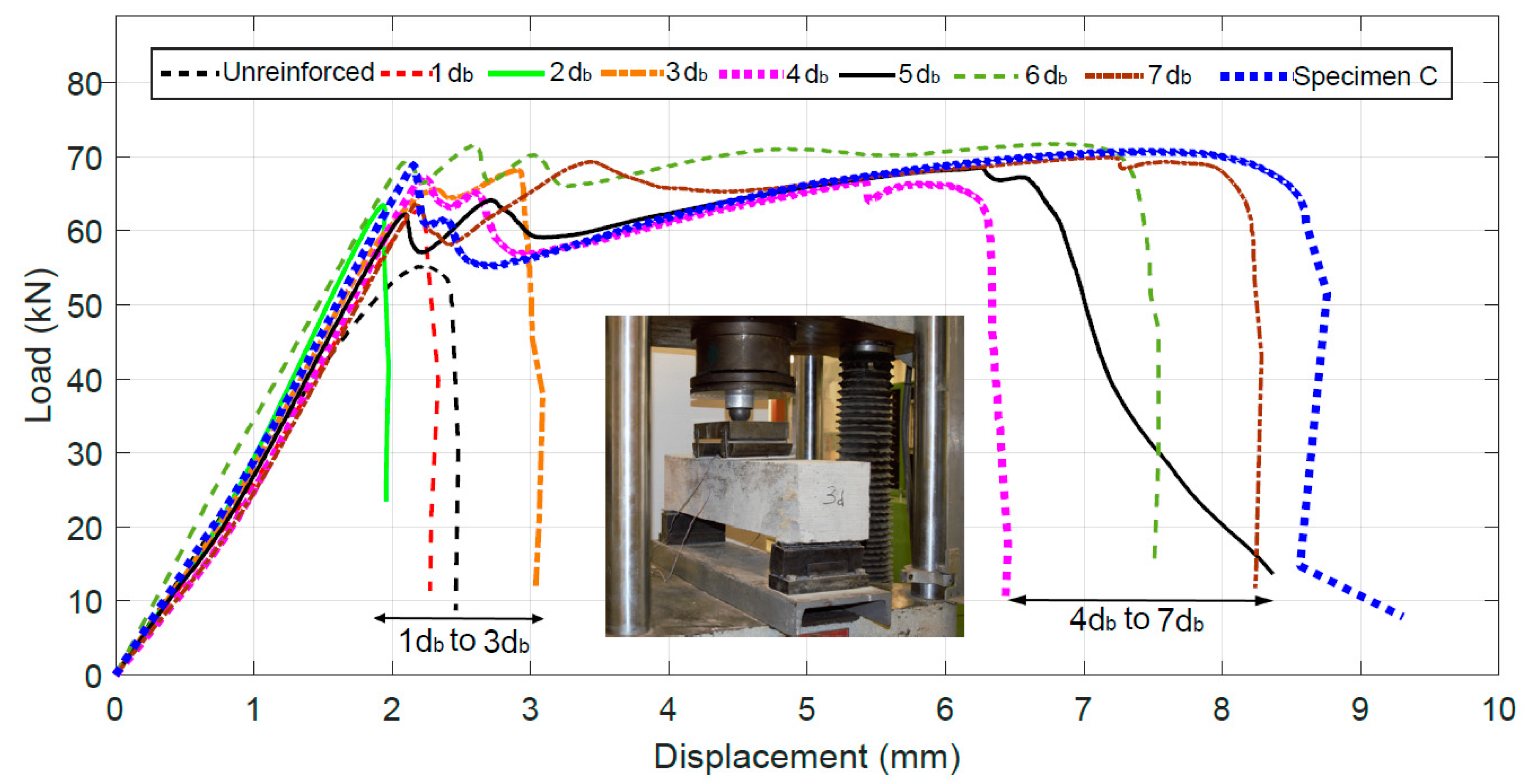
A median load-displacement curve for each lap splice length, unreinforced beams, and control beam are shown in Figure 7. All specimens were tested until failure. All control specimens failed due to bar rupture. For all specimens with lap splice length between 1db and 5db, the failure was observed due to bar slippage. For specimens with lap splice length of 6db and 7db, both modes of failure (bar rupture and bar slippage) were observed. Figure 8 shows the failure mode as of bar slippage for 5db lap splice specimen and bar rupture for 7db lap splice specimen.
The maximum rebar strain for lap splice length of 1db, 2db, 3db, 4db, 5db, 6db, and 7db was found to be 0.04%±0.016%, 0.08%±0.016%, 0.12%±0.025%, 0.19%±0.022%, 0.32%±0.035%, 1.78%±0.057%, and 2.10%±0.056% respectively. The maximum tensile strain in the rebar before failure for each lap splice length is shown in Figure 9. The yield of splice bar first occurred at 5db lap splice length. The minimum lap splice length required for uncoated steel bars in PMMA polymer concrete with concrete cover of 3db to achieve yield in the rebar was found to be 4.1db.
3.3. Shear Strength Test Results
All the beams failed in shear. One diagonal crack propagated between the loading point and the support of the beam as shown in Figure 10. The failure plane indicates that for normal concrete the failure happened by crack propagation around the aggregate at the interfacial transition zone (ITZ). However, for the PMMA-PC samples, the failure happened through aggregate because of the high adhesion at ITZ.
4. Discussion
In order to explore the use of PMMA-PC as an alternative to UHPC in closure joint between the precast deck panels, a comparison between the two materials in development length, lap splice length and, shear strength was conducted to decide if PMMA-PC provides advantages over UHPC as closure pour material. For development length, the required development length for uncoated steel bars embedded in normal concrete with similar compressive strength is at least 18 times the bar diameter. For UHPC, the development length was found experimentally to range between 6–8 times the steel bar diameters [6,21]. On the other hand, the required development length of steel bars embedded in PMMA-PC was found to be less than 4.5 times the steel bar diameter (3.6 for bar size #13 (12.7 mm) and 4.1 for bar size #16 (15.9 mm). The development length necessary for embedding the steel reinforcement in bridge deck closure joints for PMMA-PC is almost half of that of UHPC. The experimental investigations show that PMMA-PC has superior bond strength with steel compared to normal concrete and UHPC. This makes the PMMA-PC a very suitable material for deck closure joints in precast bridges. Figure 11a shows development length comparison between UHPC and PMMA-PC for bar sizes #13 (12.7 mm) and #16 (15.9 mm) as multipliers of bar diameters.
For lap splice length, the minimum lap splice length required for uncoated steel bars in PMMA-PC with concrete cover of 3db to achieve yield in the rebar was found to be 4.1db. Comparing to UHPC, 4.5db (typically is taken as 75% of embedment length) is the sufficient lap splice length to observe yielding in the rebar [5]. Figure 11b shows lap splice length comparison between UHPC and PMMA-PC for bar size #13 as multipliers of bar diameter. Furthermore, PMMA-PC could obtain a shear strength of 7.57 MPa significantly higher than both NC (344% higher) and UHPC (190%). The obtained shear strength for PMMA-PC is higher by 537% compared with the predicted AASHTO shear strength based on Equation (2) [3]. Figure 11c shows shear strength comparison between UHPC and PMMA-PC. The greater shear strength PMMA-PC confirms the possible use of this concrete for haunches between superstructure girders and full-depth precast deck panels. The comparison between PMMA-PC and UHPC shows that PMMA-PC could be used as a filler for bridge deck closure joints with smaller joint size and at the haunches between superstructure girders and full-depth precast deck panels.
5. Closure Joint Design Example
The benefit of using PMMA-PC in closure joints between full-depth precast deck panels can be demonstrated using a design example. Therefore, we examined the design of closure joint for a 2-span bridge with 24.4 m spans (measured from backwall to centerline of the intermediate pier). The closure joint was designed twice, first using PMMA-PC closure joint, and second using UHPC closure joint. Both designs have the same design assumption of using panel width between 2.44 m and 3.04 m with an intermediate link slab to design the bridge continuous for live loads. The panel longitudinal reinforcement was #16 at the bottom and #13 at the top for all panels except for link slab. However, link slabs were designed with #16 at top and bottom. Longitudinal reinforcement is used to resist shrinkage and cracking.
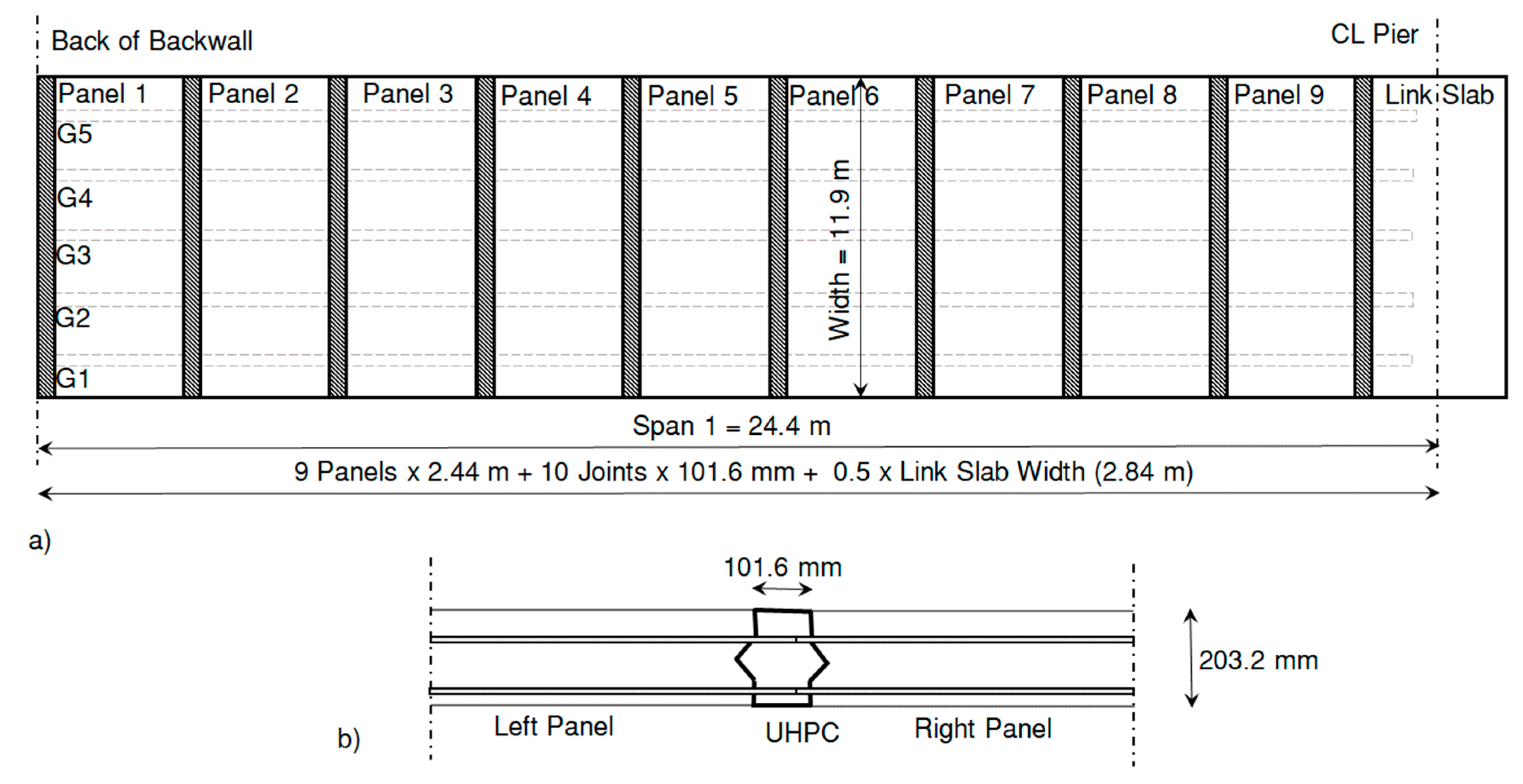
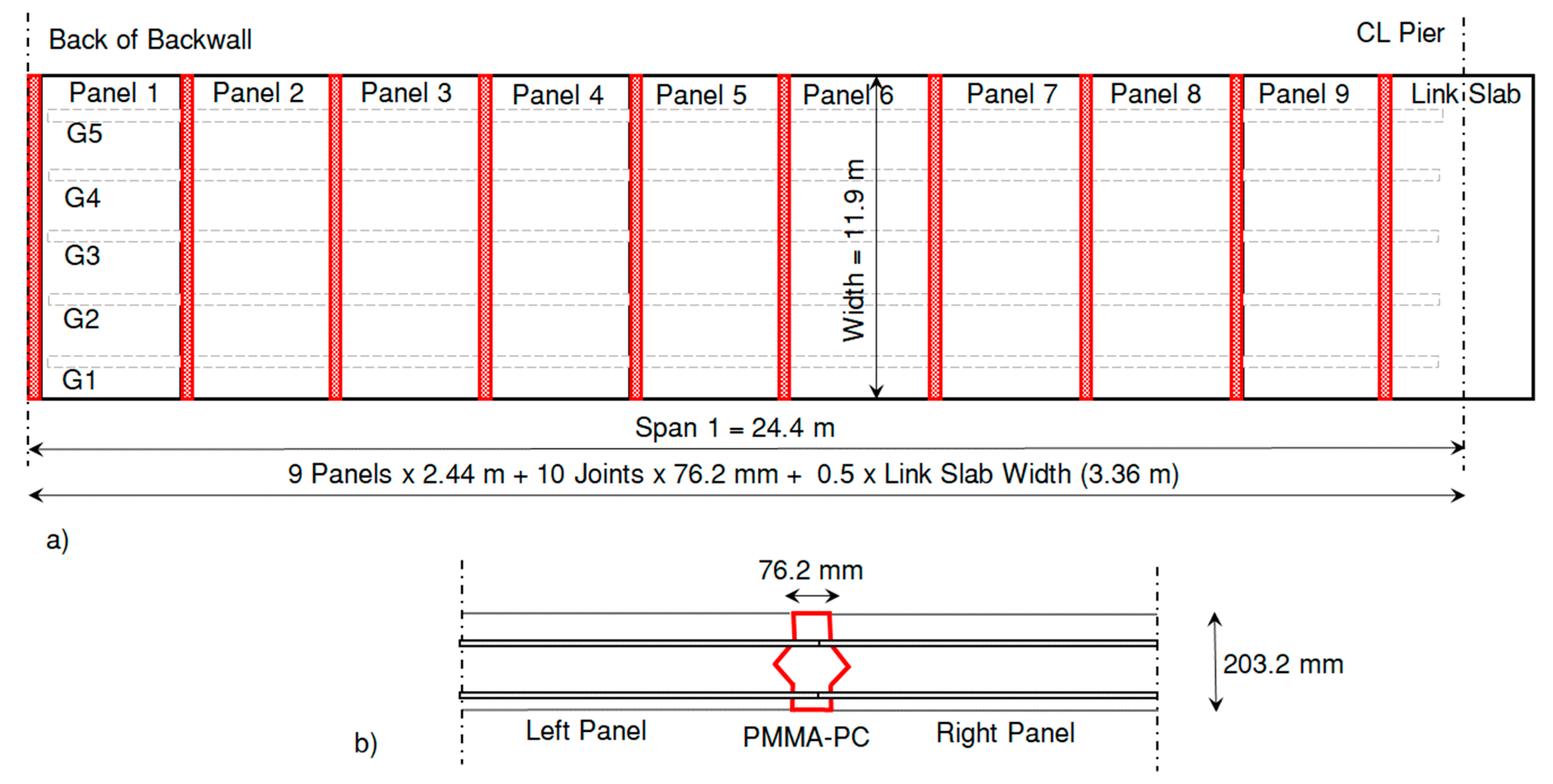
Eighteen full-depth precast deck panels in addition to one intermediate link slab were supported over five prestressed concrete girders; link slab width length was 11.9 m, however, the widths were 2.84 m and 3.36 m for the case of UHPC closure joint and PMMA-PC closure joint respectively. Full-depth precast deck panels were typical of 2.44 m width and 11.9 m length. Figure 12 and Figure 13 show panel layout and joint size for one span with UHPC and PMMA-PC closure joints respectively.
UHPC joint size was determined using development length of 6db, therefore the joint width was chosen to be 101.6 mm with lap splice between bars of 75% of the development length (76.2 mm) using recommendations from [5]. The joint size is based on bar #16 (15.9 mm). For PMMA-PC joints, the minimum development length and lap splice were 4.1db, therefore PMMA-PC joint size was chosen to be 76.2 mm with lap splice length of 70 mm.
Table 4 lists the design comparison between UHPC and PMMA-PC designs for closure joints. The total volume required for UHPC is 5.60 m3 versus 4.4 m3, about a 22% saving in the volume of closure joint material. A cubic meter of UHPC costs $5,230 whereas a cubic meter of PMMA-PC costs $2,615 per factory directions at a total of 60% savings in direct costs related to closure joint casting with 22% savings in volume of in-situ castings, which makes stronger, more durable and faster ABC. It is evident that PMMA-PC is an excellent material and an economic viable design alternative for deck closure joints in ABC.
6. Conclusions and Findings
In order to increase durability of closure joints between precast deck panels in accelerated bridge construction (ABC), polymer concrete is suggested as an economic alternative material due to its high corrosion resistance and very good resistance to cracking, unlike cementitious material. A research investigation was carried out to explore the use of PMMA-PC as filler material for deck closure joints. Various reinforcing steel bar development lengths and lap splice lengths were tested using pull-out and lap splice test setups respectively for bar size #13 (12.7 mm) and #16 (15.9 mm). In addition, shear strength test was conducted to identify the shear capacity of PMMA-PC as it is common practice to use the same filler material between precast deck panels and at haunches between superstructure girders and precast deck panels. Several conclusions and findings can be drawn from the testing and exploration of PMMA-PC as a good alternative for closure joints:
- The minimum development length required for steel bars embedded in PMMA-PC was found to range between 3.6 and 4.1 times the reinforcing bar diameter. This development length is almost one-half of the minimum development length of UHPC and is one-fifth that required by AASHTO for normal concrete.
- The minimum lap splice length required for uncoated steel bars in PMMA-PC with concrete cover of 3 times the reinforcing bar diameter to achieve yield in the rebar was found to be 4.1 times the reinforcing bar diameter. Comparing to UHPC, 4.5 times the reinforcing bar diameter is enough lap splice length to observe yielding in the rebar. The splice length is also 40% of what required by AASHTO for normal concrete.
- PMMA-PC has shear strength of 7.57 MPa, significantly higher than both normal concrete (+344%) and UHPC (+190%) and much higher than the shear strength expected by AASHTO.
- It is obvious that PMMA-PC provides an excellent opportunity for making a relatively small closure joint compared with all other alternative concretes. Testing of PMMA-PC and a practical design example show that PMMA-PC is an excellent alternative for bridge deck closure joints and requires significantly narrower precast gap spacing compared with UHPC associated with direct and indirect cost saving.
Author Contributions
Investigation: I.M. and R.C. and M.G. and M.R.T., Lab Work: R.C. and M.G., Supervision: M.R.T., First Draft: I.M. & M.G., Paper Writing: I.M., Paper Writing Review: M.R.T., Final Paper Review: I.M. & M.R.T., Team Lead: M.R.T.
Funding
This research received no external funding. Materials were donated by Transpo Industries Inc.
Acknowledgments
The authors greatly acknowledge the internal support by University of New Mexico. The authors would like to thank Transpo, Inc. for supplying the polymer concrete materials.
Conflicts of Interest
Authors declare no conflict of Interest.
References
- Culmo, M.P. Accelerated Bridge Construction-Experience in Design, Fabrication and Erection of Prefabricated Bridge Elements and Systems; Report No. FHWA-HIF-12-013; USDOT FHWA: Washington, DC, USA, 2011.
- ACI (American Concrete Institute). Building Code Requirements for Structural Concrete; ACI 318-14; ACI: Farmington Hills, MI, USA, 2014. [Google Scholar]
- AASHTO (American Association of State Highway and Transportation Officials). AAHSTO LRFD Bridge Design Specifications, 7th ed.; American Association of State Highway and Transportation Officials: Washington, DC, USA, 2014. [Google Scholar]
- Graybeal, B. Ultra-High Performance Concrete; Report No. FHWA-HRT-11-038; USDOT FHWA: Washington, DC, USA, 2011; p. 8.
- Yuan, J.; Graybeal, B.A. Bond Behavior of Reinforcing Steel in Ultra-High Performance Concrete; Report No. FHWA-HRT-14-090; USDOT: Washington, DC, USA, 2014.
- Graybeal, B. Design and Construction of Field-Cast UHPC Connections; Report No. FHWA-HRT-14-084; USDOT FHWA: Washington, DC, USA, 2014.
- Reda, M.M.; Shrive, N.G.; Gillott, J.E. Microstructural investigation of innovative UHPC. Cem. Concr. Res. 1999, 29, 323–329. [Google Scholar] [CrossRef]
- Bhanja, S.; Sengupta, B. Optimum silica fume content and its mode of action on concrete. ACI Mater. J. 2003, 100, 407–412. [Google Scholar]
- Schießl, P.; Mazanec, O.; Lowke, D. SCC and UHPC—Effect of mixing technology on fresh concrete properties. In Advances in Construction Materials; Springer: Berlin/Heidelberg, Germany, 2007; pp. 513–522. [Google Scholar]
- ACI (American Concrete Institute). Guide for the Use of Polymers in Concrete; ACI 548.1R-09; ACI: Farmington Hills, MI, USA, 2009. [Google Scholar]
- Rebeiz, K.S.; Serhal, S.P.; Craft, A.P. Properties of polymer concrete using fly ash. J. Mater. Civ. Eng. 2004, 16, 15–19. [Google Scholar] [CrossRef]
- Gorninski, J.P.; Dal Molin, D.C.; Kazmierczak, C.S. Comparative assessment of isophtalic and orthophtalic polyester polymer concrete: Different costs, similar mechanical properties and durability. Constr. Build. Mater. 2007, 21, 546–555. [Google Scholar] [CrossRef]
- Czarnecki, L.; Chmielewska, B. The influence of coupling agent on the properties of vinylester mortar. In Proceedings of the II International RILEM Symposium on Adhesion between Polymers and Concrete; RILEM: Paris, France, 1999; Volume 99, pp. 57–66. [Google Scholar]
- Wheat, D.L.; Fowler, D.W.; Al-Negheimish, A.I. Thermal and fatigue behavior of polymer concrete overlaid beams. J. Mater. Civ. Eng. 1993, 5, 460–477. [Google Scholar] [CrossRef]
- Whitney, D.P.; Fowler, D.W. New applications for polymer overlays. Adv. Mater. Res. 2015, 1129, 277–282. [Google Scholar] [CrossRef]
- ASTM C39-17b. Standard Test Method for Compressive Strength of Cylindrical Concrete Specimens; ASTM C39-17b; ASTM International: West Conshohocken, PA, USA, 2017. [Google Scholar]
- ASTM C496-17. Standard Test Method for Splitting Tensile Strength of Cylindrical Concrete Specimens; ASTM C496-17; ASTM International: West Conshohocken, PA, USA, 2017. [Google Scholar]
- Graybeal, B. Bond Behavior of Reinforcing Steel in Ultra-High Performance Concrete; Report No. FHWA-HRT-14-089; USDOT FHWA: Washington, DC, USA, 2014.
- Esfahani, M.R.; Rangan, B.V. Bond between normal strength and high-strength concrete (HSC) and reinforcing bars in splices in beams. Struct. J. 1998, 95, 272–280. [Google Scholar]
- Shuraim, A.B. A novel approach for evaluating the concrete shear strength in reinforced concrete beams. Lat. Am. J. Solids Struct. 2014, 11, 93–112. [Google Scholar] [CrossRef] [Green Version]
- Saleem, M.A.; Mirmiran, A.; Xia, J.; Mackie, K. Development length of high-strength steel rebar in ultrahigh performance concrete. J. Mater. Civ. Eng. 2012, 25, 991–998. [Google Scholar] [CrossRef]
Figure 1.
Schematic for full-depth deck precast panel used in ABC: (a) construction of precast deck panels; (b) actual construction [6].
Figure 1.
Schematic for full-depth deck precast panel used in ABC: (a) construction of precast deck panels; (b) actual construction [6].

Figure 2.
Polymer concrete production.

Figure 3.
Test setups: (a) pull-out test setup; (b) lap splice test setup; (c) shear strength test setup.
Figure 3.
Test setups: (a) pull-out test setup; (b) lap splice test setup; (c) shear strength test setup.

Figure 4.
Failure due to: (a) Debonding of bar for embedment length 4db; (b) bar rupture for embedment length of 6db; (c) Debonding of bar for embedment length of 6db; (d) bar rupture for embedment length of 10db (similar failure observed for 8db).
Figure 4.
Failure due to: (a) Debonding of bar for embedment length 4db; (b) bar rupture for embedment length of 6db; (c) Debonding of bar for embedment length of 6db; (d) bar rupture for embedment length of 10db (similar failure observed for 8db).
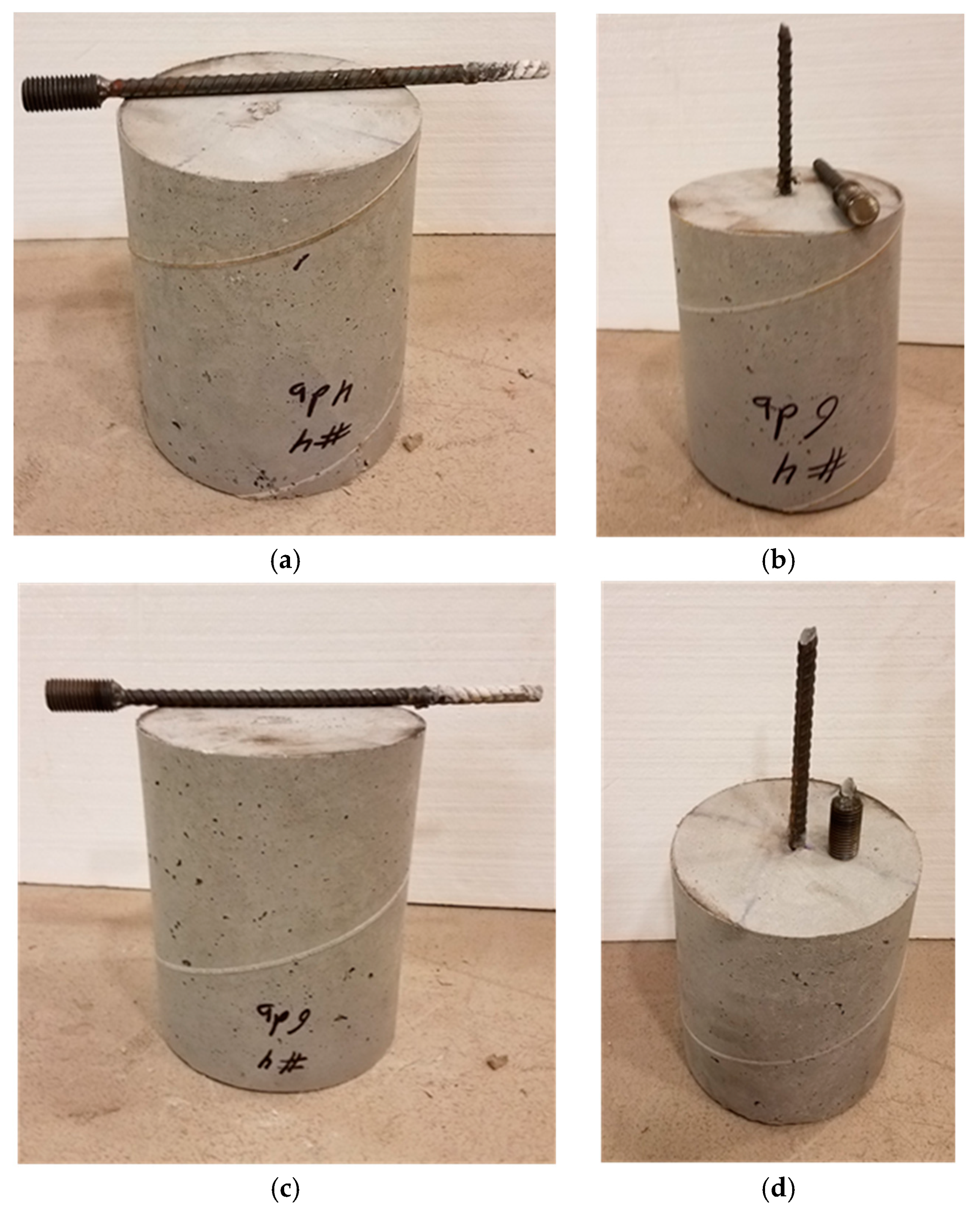
Figure 5.
Median load-displacement curve for pull-out test: (a) #13 (12.7 mm) rebar for all four embedment lengths; (b) #16 (15.9 mm) rebar for all four embedment lengths.
Figure 5.
Median load-displacement curve for pull-out test: (a) #13 (12.7 mm) rebar for all four embedment lengths; (b) #16 (15.9 mm) rebar for all four embedment lengths.

Figure 6.
Pull-out test results for bar #13 (12.7 mm) and #16 (15.9 mm): (a) load at failure; (b) stress in bar at failure; (c) bond stress.
Figure 6.
Pull-out test results for bar #13 (12.7 mm) and #16 (15.9 mm): (a) load at failure; (b) stress in bar at failure; (c) bond stress.
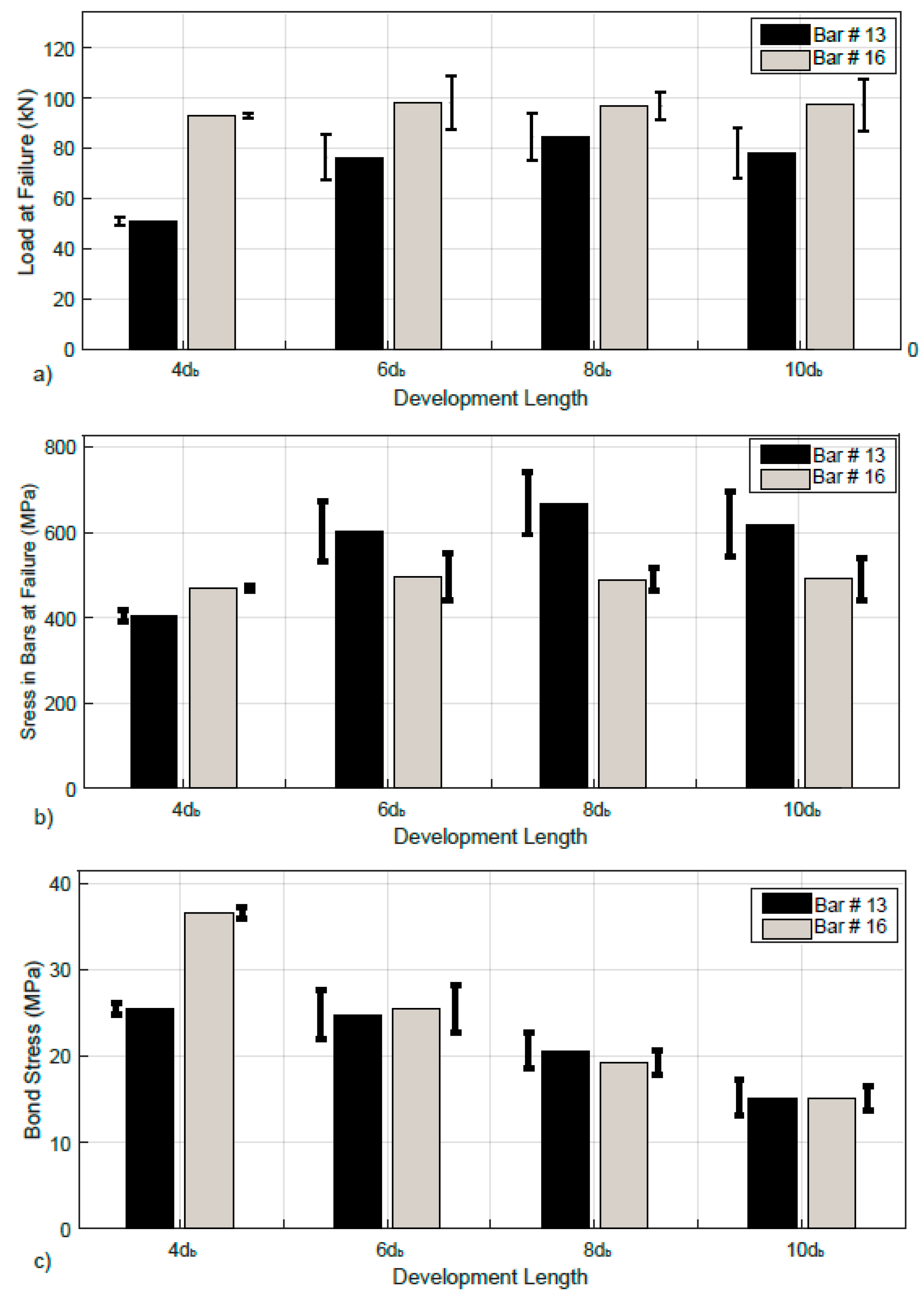
Figure 7.
Load-displacement curve for lap splice length, unreinforced beams, and control beams.

Figure 8.
Modes of failure for lap splice: (a) bar slippage for lap splice length of 5db; (b) bar rupture for lap splice length of 7db.
Figure 8.
Modes of failure for lap splice: (a) bar slippage for lap splice length of 5db; (b) bar rupture for lap splice length of 7db.

Figure 9.
The maximum tensile strain in the rebar before failure for each lap splice length (red line represents the yield strain of the steel rebar “0.20%”).
Figure 9.
The maximum tensile strain in the rebar before failure for each lap splice length (red line represents the yield strain of the steel rebar “0.20%”).
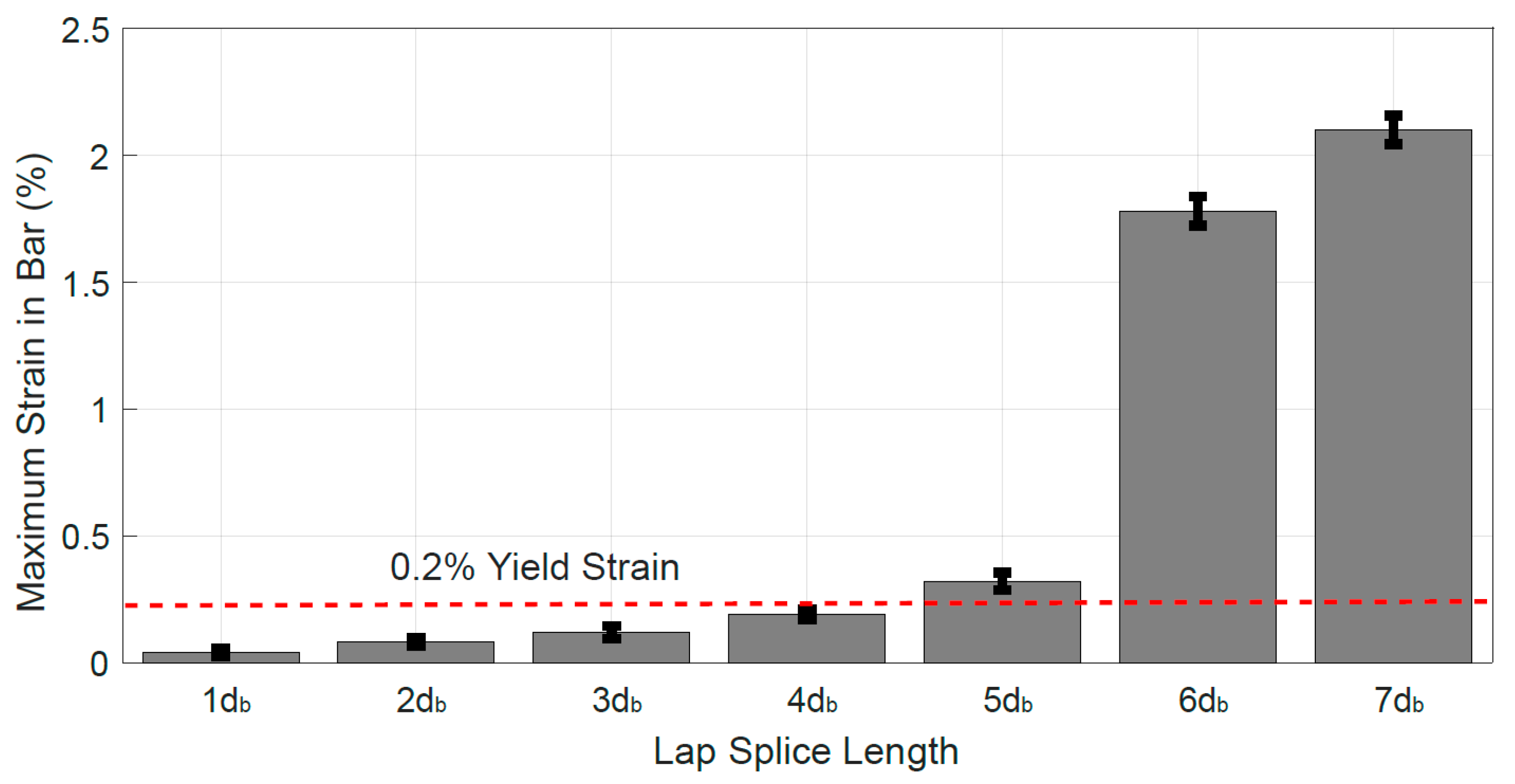
Figure 10.
Shear failure of: (a) Normal concrete (NC); (b) Ultra High Performance Concrete; (c) PMMA-PC.
Figure 10.
Shear failure of: (a) Normal concrete (NC); (b) Ultra High Performance Concrete; (c) PMMA-PC.
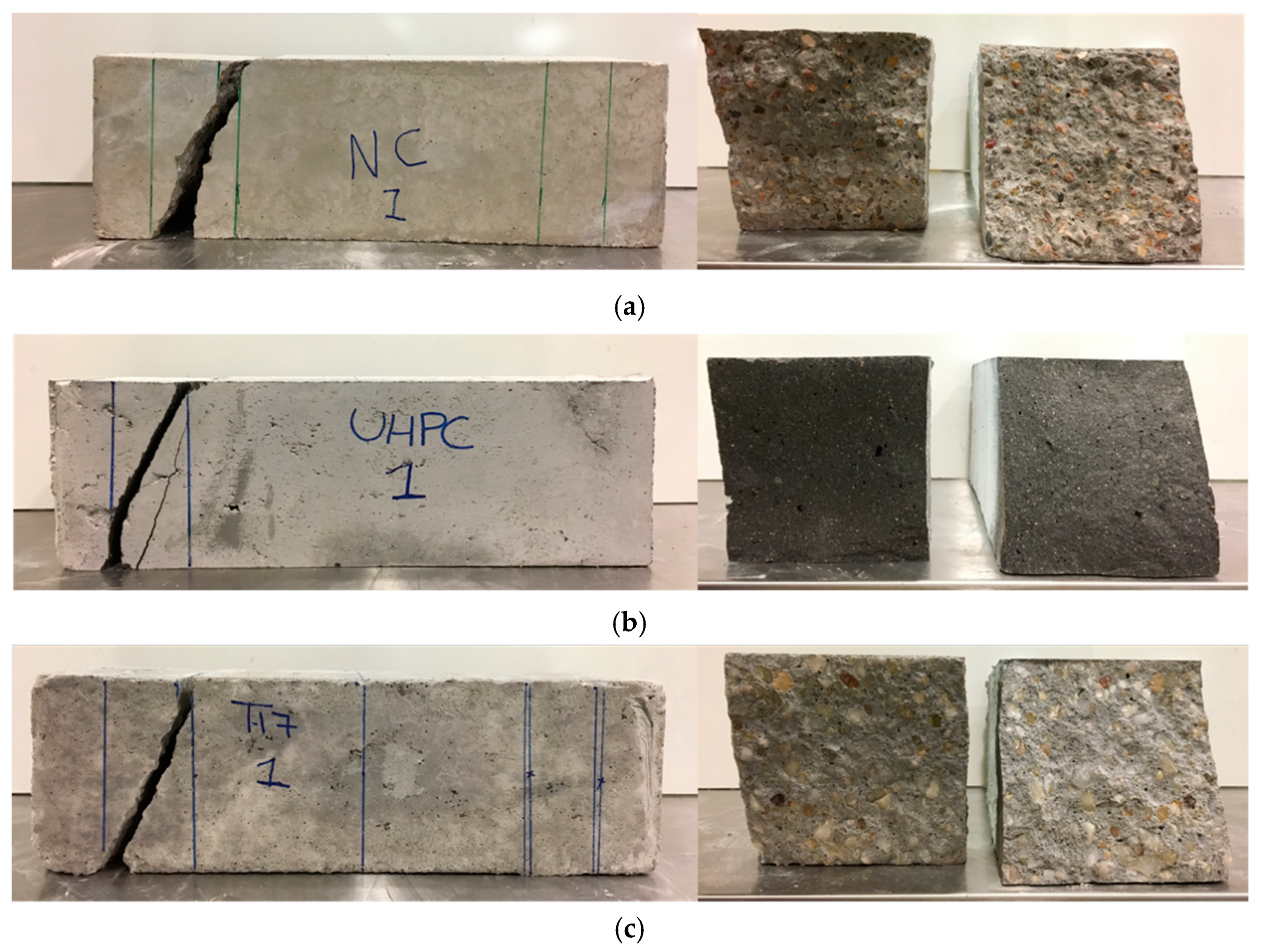
Figure 11.
Test result comparison between PC and UHPC: (a) development length; (b) lap splice length; (c) shear strength.
Figure 11.
Test result comparison between PC and UHPC: (a) development length; (b) lap splice length; (c) shear strength.
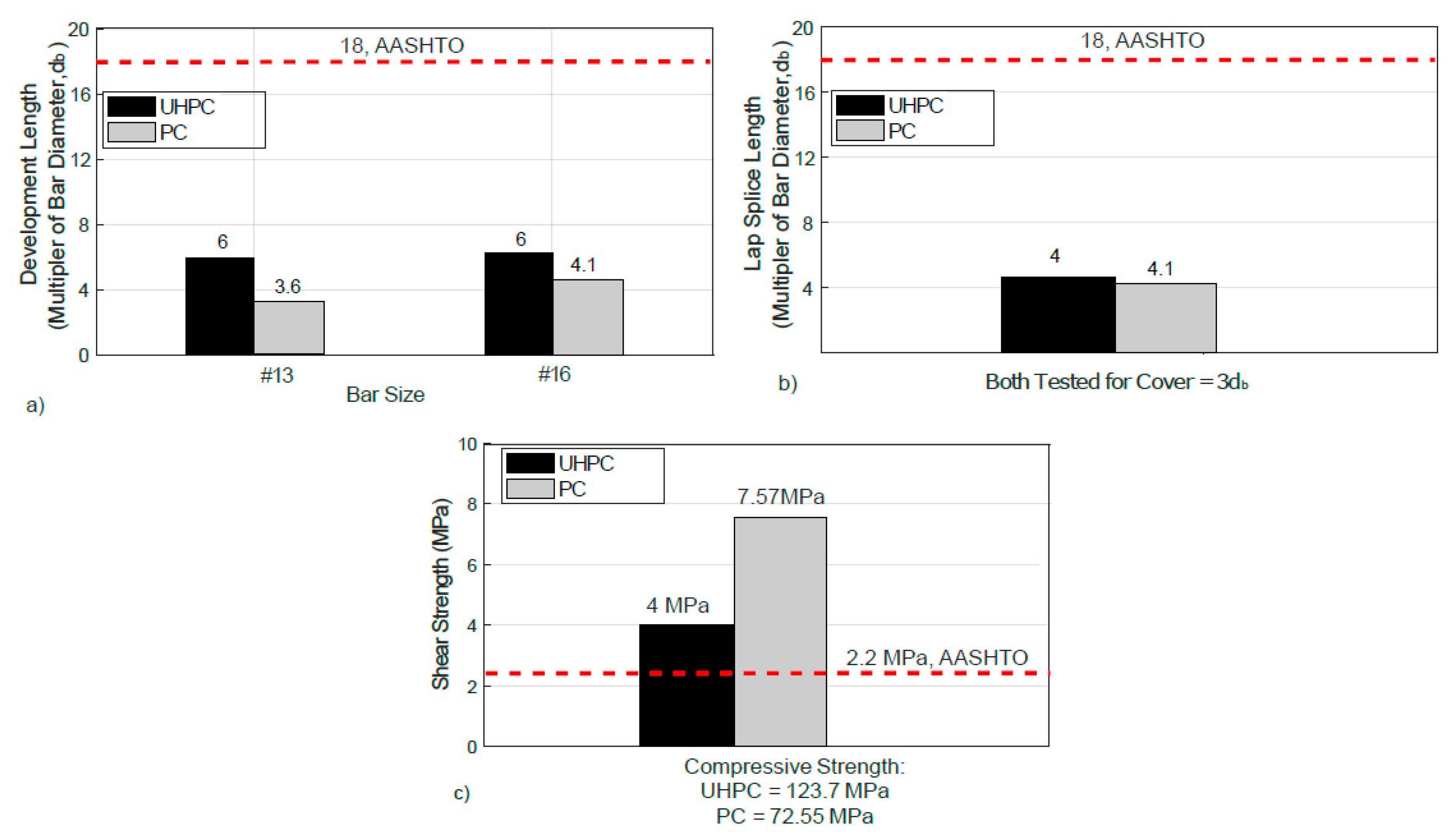
Figure 12.
Bridge example with precast deck panel using UHPC joints: (a) panel layout; (b) joint size.
Figure 12.
Bridge example with precast deck panel using UHPC joints: (a) panel layout; (b) joint size.

Figure 13.
Bridge example with precast deck panel using PMMA-PC joints: (a) panel layout; (b) joint size.
Figure 13.
Bridge example with precast deck panel using PMMA-PC joints: (a) panel layout; (b) joint size.


Table 1.
Mixture Proportions of PMMA-PC (kg/m3) and Mechanical Properties (MPa).
| PMMA-PC | Properties | |
|---|---|---|
| Mixture | MMA Polymer | 159.5 |
| Aggregate | 2224.6 | |
| Compressive strength | 72.6 ±2.1 | |
| Split tensile strength | 6.6 ± 0.6 |
Table 2.
Mixture Proportions of Ultra-High Performance Concrete (UHPC) (kg/m3).
| Cement | 1029 |
| Water | 227.5 |
| Aggregate (Clean Medium Sand) | 910 |
| Silica Fume | 306.6 |
| Superplasticizer (Glenium 3030 NS) | 26.7 |
Table 3.
Average Peak Load and Rebar Stress at Failure for Pull-Out Test.
| Development Length | Average Load (kN) at Failure | Average Failure Stress (MPa) in rebar | ||
|---|---|---|---|---|
| Bar #13 (12.7 mm) | Bar #16 (15.9 mm) | Bar #13 (12.7 mm) | Bar #16 (15.9 mm) | |
| 4db | 51.3 ± 1.8 | 93.0 ± 1.0 | 404.8 ± 14.1 | 469.8 ± 4.9 |
| 6db | 76.4 ± 8.9 | 98.1 ± 10.8 | 602.9 ± 70.0 | 495.8 ± 54.5 |
| 8db | 84.6 ± 9.2 | 7.0 ± 5.3 | 667.6 ± 72.4 | 490.1 ± 27.0 |
| 10db | 78.3 ± 9.9 | 97.4 ± 10.1 | 618.4 ± 77.8 | 491.9 ± 50.8 |
Table 4.
Design Comparison Between UHPC and PMMA-PC Closure Joints.
| Design Parameter | UHPC | PMMA-PC |
|---|---|---|
| Panel Dimension (m) | 2.44 width | 2.44 width |
| 11.9 length | 11.9 length | |
| Link Slab Dimension (m) | 2.84 width | 3.36 width |
| 11.9 length | 11.9 length | |
| Top Longitudinal Reinforcement for Panels | #13 (12.7 mm) | #13 (12.7 mm) |
| Bottom Longitudinal Reinforcement for Panels | #16 (15.9 mm) | #16 (15.9 mm) |
| Top Longitudinal Reinforcement for Link Slab | #16 (15.9 mm) | #16 (15.9 mm) |
| Bottom Longitudinal Reinforcement for Link Slab | #16 (15.9 mm) | #16 (15.9 mm) |
| Closure Joint Width | 101.6 mm | 76.2 mm |
| Embedment Length | 95.3 mm | 70 mm |
| Lap Splice Length | 76.2 mm | 70 mm |
| Volume of Closure Joint Material | 5.60 m3 | 4.40 m3 |
| Unit Cost of Closure Joint Material | $5230/m3 | $2615/m3 |
| Cost of Closure Joint Material | $29,280 | $11,500 (saving $17,780) |
© 2019 by the authors. Licensee MDPI, Basel, Switzerland. This article is an open access article distributed under the terms and conditions of the Creative Commons Attribution (CC BY) license (http://creativecommons.org/licenses/by/4.0/).
Share and Cite
MDPI and ACS Style
Mantawy, I.; Chennareddy, R.; Genedy, M.; Taha, M.R. Polymer Concrete for Bridge Deck Closure Joints in Accelerated Bridge Construction. Infrastructures 2019, 4, 31. https://0-doi-org.brum.beds.ac.uk/10.3390/infrastructures4020031
AMA Style
Mantawy I, Chennareddy R, Genedy M, Taha MR. Polymer Concrete for Bridge Deck Closure Joints in Accelerated Bridge Construction. Infrastructures. 2019; 4(2):31. https://0-doi-org.brum.beds.ac.uk/10.3390/infrastructures4020031
Chicago/Turabian StyleMantawy, Islam, Rahulreddy Chennareddy, Moneeb Genedy, and Mahmoud Reda Taha. 2019. "Polymer Concrete for Bridge Deck Closure Joints in Accelerated Bridge Construction" Infrastructures 4, no. 2: 31. https://0-doi-org.brum.beds.ac.uk/10.3390/infrastructures4020031