Blast Loading Response of Reinforced Concrete Panels Externally Reinforced with Steel Strips


School of Civil and Environmental Engineering, National University of Science and Technology, Sector H-12, Islamabad 44000, Pakistan
*
Author to whom correspondence should be addressed.
Infrastructures 2019, 4(3), 54; https://0-doi-org.brum.beds.ac.uk/10.3390/infrastructures4030054
Submission received: 31 May 2019
/
Revised: 8 August 2019
/
Accepted: 9 August 2019
/
Published: 18 August 2019
Abstract
:Frequent terrorist activities, the use of vehicle bomb blasts and improvised explosive devices (IEDs) have brought forth the task of protection against blasts as a priority issue for engineers. Terrorists mostly target the areas where human and economic losses are significantly higher. It is really challenging to study the effects of blast loading on structures due to numerous variables. For instance, the type of detonation charge, explosive material, placement of charge and standoff distance, etc., are a few of the variables which make the system more complicated. Reinforced cement concrete (RCC) wall panels are commonly used for protecting important installations and buildings. In this research, the response of RCC wall panels has been investigated due to the blast effect caused by two TNT charge weights of 50 kg and 100 kg. These two charge weights have been selected after a detailed study of terrorist activities in the recent past. For this purpose, an existing arrangement at an important military installation, i.e., NESCOM Hospital Islamabad in Pakistan, has been selected. To reduce computational efforts, three RCC wall panels, placed side by side producing a continuous front along with a corresponding boundary and structural wall, have been considered. RCC wall panels are placed at a distance of 3 ft from the perimeter of the boundary wall and 23 ft from the structural wall. The displacement on the front face of RCC wall panels and the structural wall is measured at three levels of top, middle and bottom. ANSYS AUTODYN software has been used to simulate the model. Analysis has been carried out to identify and study the weakness of existing arrangements. Literature was reviewed for suggesting an appropriate strengthening technique for existing structures against blast loading. It was found that in addition to existing strengthening techniques, use of steel strips is amongst the most feasible technique for strengthening existing structures. It not only significantly enhanced the blast performance of structures, but it also significantly reduced z-direction displacements and pressures. The results show that the use of steel strips as the improvement technique for already placed RCC wall panels can be effective against a blast loading of up to 100 kg TNT.
1. Introduction
Blast explosions and terrorist attacks at different public and military places have increased considerably during the last decade [1]. Lifeline structures are the most vulnerable targets for terrorist activities. Terrorists mostly fix their targets at places where human and economic losses are significantly higher. Hospitals, schools and government buildings are easy targets for terrorists [2]. Terrorist activities result in the loss and injury of thousands of human lives and in catastrophic damage to infrastructure around the globe. Blast events near buildings may damage structural and non-structural members. Major damage caused from blast explosions is due to huge dynamic force, which is usually more than the anticipated design load, which ultimately causes the structure to collapse [3]. It is challenging to analyze and design the structures against blast loading because of incalculable blast scenarios. It is really challenging to study the effects of blast loading on structures due to numerous variables such as the kind of detonation charge, material, placement and standoff distance. Hence, for the designing of blast resistant structures, maximum possible scenarios are necessary to be studied which may not be achievable without the use of software.
Reinforced concrete structures are widely used in the construction industry [4]. Reinforced cement concrete (RCC) structures are designed for specific loading. However, due to frequent terrorist activities and blast explosions, these structures face severe loading [1]. Blast loading acts for a very short duration and is much greater than designed loads [3]. Due to the large dynamic loading, structural members fail [2] and casualties/injuries occur. To cater to the effects of blast loading on structures, different protective/retrofitting techniques have been identified. Previous studies have shown that aramid fiber reinforced plastics (AFRP) [5], fiber reinforced polymers (FRP) [6], ultra-high performance fiber reinforced concrete [7], glass fiber reinforced polymers (GFRP) [8], carbon fiber reinforced polymers [9], polyurethane elastomers [10], steel jacketing [11], strain hardening cementations composites [12], steel plates [13], glass curtain walls [14] and RCC wall panels [15] are the available strengthening/retrofitting techniques used against blast loading.
Numerical evaluations of the blast resistance of RCC slabs strengthened with aramid fiber reinforced plastics showed that the strength of the AFRP slab is 20% more than GFRP and the damage of the AFRP strengthened slab is also lower than GFRP [5]. Studies on the behavior of ultra-high performance fiber reinforced concrete (UHPFRC) and HSRC columns subjected to blast loading conclude that the post blast crack patterns, permanent deflections and different levels of damage of UHPFRC columns show superior blast loading resistance as compared to HSRC columns. Modeling the response of reinforced concrete panels under blast loading has concluded that the mass of the explosive charge and the standoff distance have greater influence on the blast response. Deflection of reinforced concrete panels can also be reduced by increasing the panel thickness and the ratio of reinforcement. Glass curtain walls with protective films have proven to be well suited for use in glazing systems that resist blast loading. A non-linear dynamic finite element code (LS-DYNA) is used to conduct the stress and deflection analysis. The analytical results on dynamic behaviors of protective films can be used to mitigate hazards from broken glazing due to blast loading.
It can be seen from literature [13,14] that there are a number of strengthening techniques, globally available for various collapse mechanisms. Keeping in mind the construction cost, it is uneconomical to design all buildings for blast loading. A security/protection wall is an economical solution against blast loading and is being used internationally at public places and lifeline structures such as hospitals, schools, offices, residential/commercial buildings and military installations.
Research Significance
Rapidly increasing terrorist activities highlight the necessity/importance of structural protection against blast loading to minimize its catastrophic effects. There is a dire need to analyze existing arrangements of structural protection against blast loading to determine its efficacy and to identify weaknesses in existing security wall panels. Based on identified structural weaknesses, it is needed to suggest a feasible improvement/strengthening technique to minimize the impact of terrorist activities and to save valuable human lives and property.
RCC wall panels are widely used as a protective barrier against blast loading due to its quick preparation, convenient transportation, erection and good energy absorbance [16]. These panels are also being used in Pakistan. Due to increased terrorist activities, RCC wall panels are placed in front of important public and military installations. There is a considerably large number of military installations and lifeline structures where RCC wall panels are used as a protective barrier against blast explosions. However, there are certain weaknesses which need to be identified and require improvements to enhance their efficacy against blast explosions.
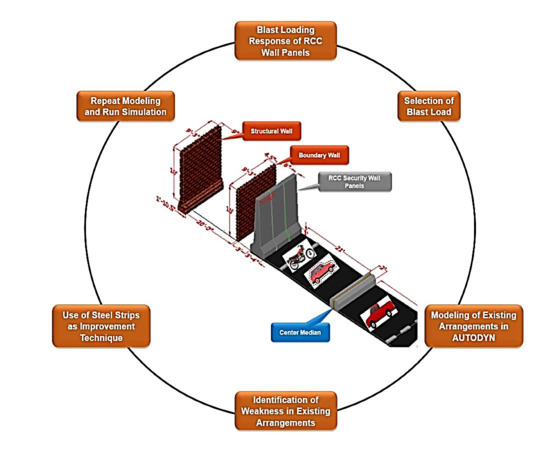
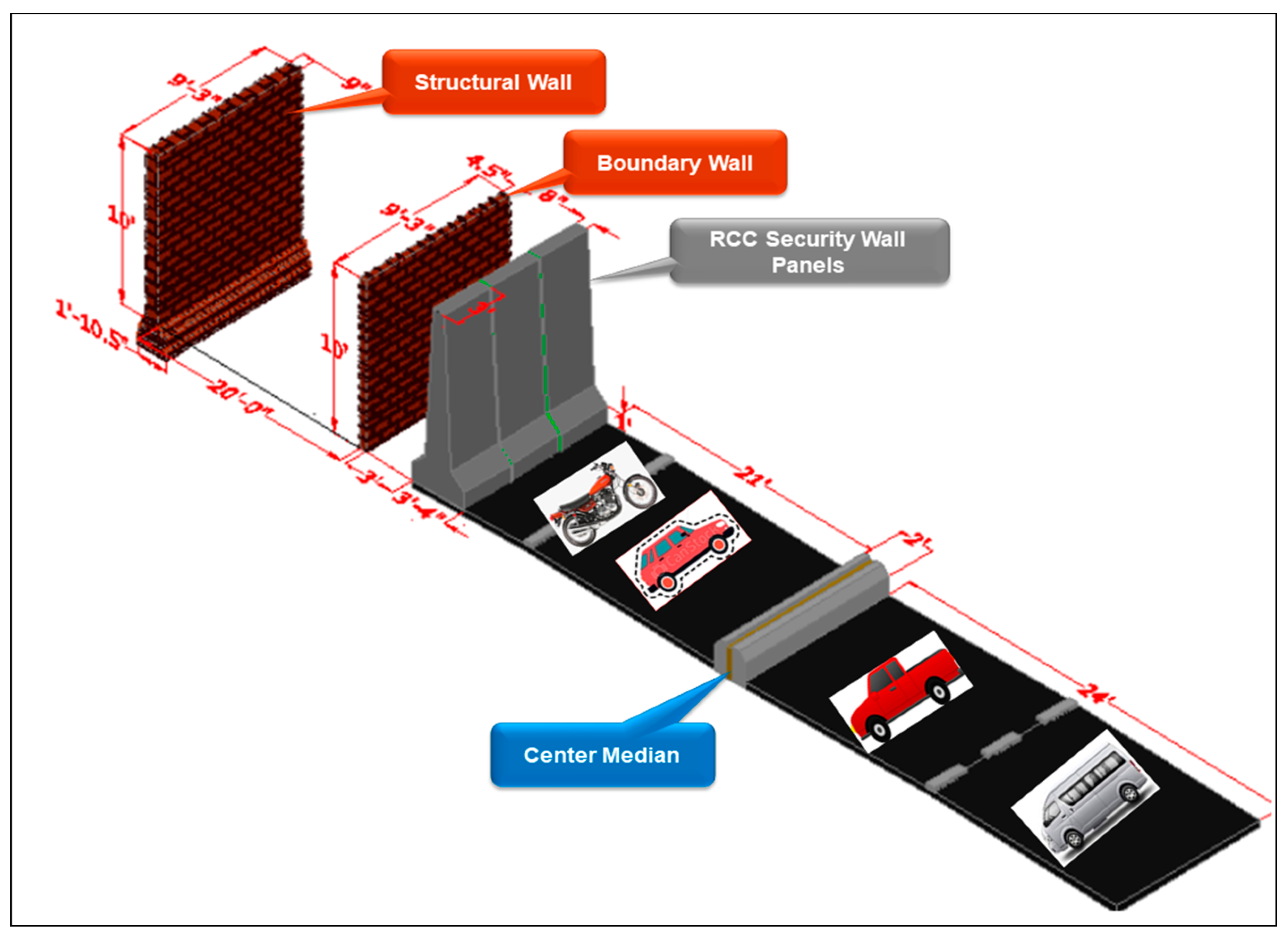
In this study, the effect of blast loading on existing RCC wall panels and the corresponding structural wall is carried out. Weaknesses in existing RCC wall panels have been identified as the base not being fixed and intermediate spacing between panels. Therefore, a feasible strengthening technique is proposed to improve their efficacy against blast explosions. For this purpose, the existing arrangement of RCC walls placed in front of an important military installation, NESCOM Hospital, Faqir Api Road, Islamabad, Pakistan has been selected. The measured distance between the RCC wall panels and a structural wall is 23 ft. The modeling was carried out using ANSYS AUTODYN 3D hydrocode software. Due to huge computational efforts, instead of modeling the whole structure, only three RCC wall panels and their corresponding structural wall were considered for analysis and its improvement. A total of two charge weights have been simulated on the basis that a motorcycle can carry 50 kg TNT and a motor car can carry 100 kg TNT. Furthermore, two TNT charge locations were considered, one at the face of the RCC wall and the other at a distance of 10 ft. The distance of 10 ft is considered on the basis that in the majority of cases, RCC wall panels are placed along the roadside. A practical case has been considered where these panels are placed in front of the building and along the roadside. Secondly, these panels are placed in populous areas where the threat of a terrorist attack is high. Two possible blast scenarios have been selected, i.e., the explosion can be at the face of the RCC wall panels and at a distance of 10 ft (middle of road) from RCC wall panels as the road width is 20.5 ft. After the analysis of the existing arrangement, a strengthening technique has been proposed by providing external steel strips which go around the whole three panels and they have restricted the displacement of RCC wall panels. The effect of blast loading is also minimized.
2. Methodology
2.1. Description of Blast Protection Wall Panels
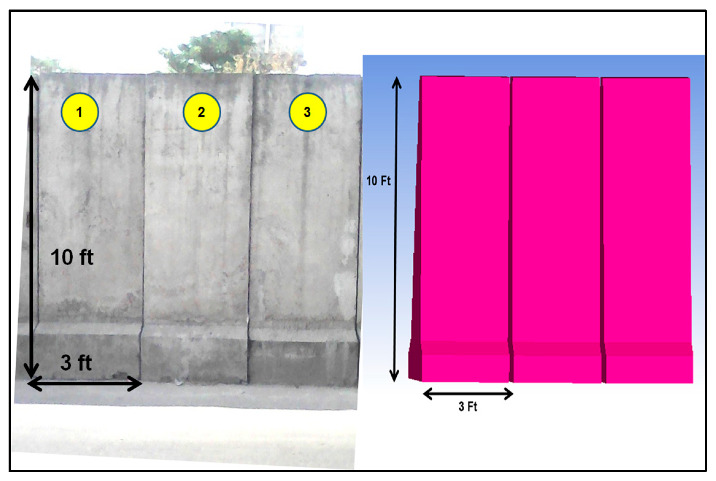
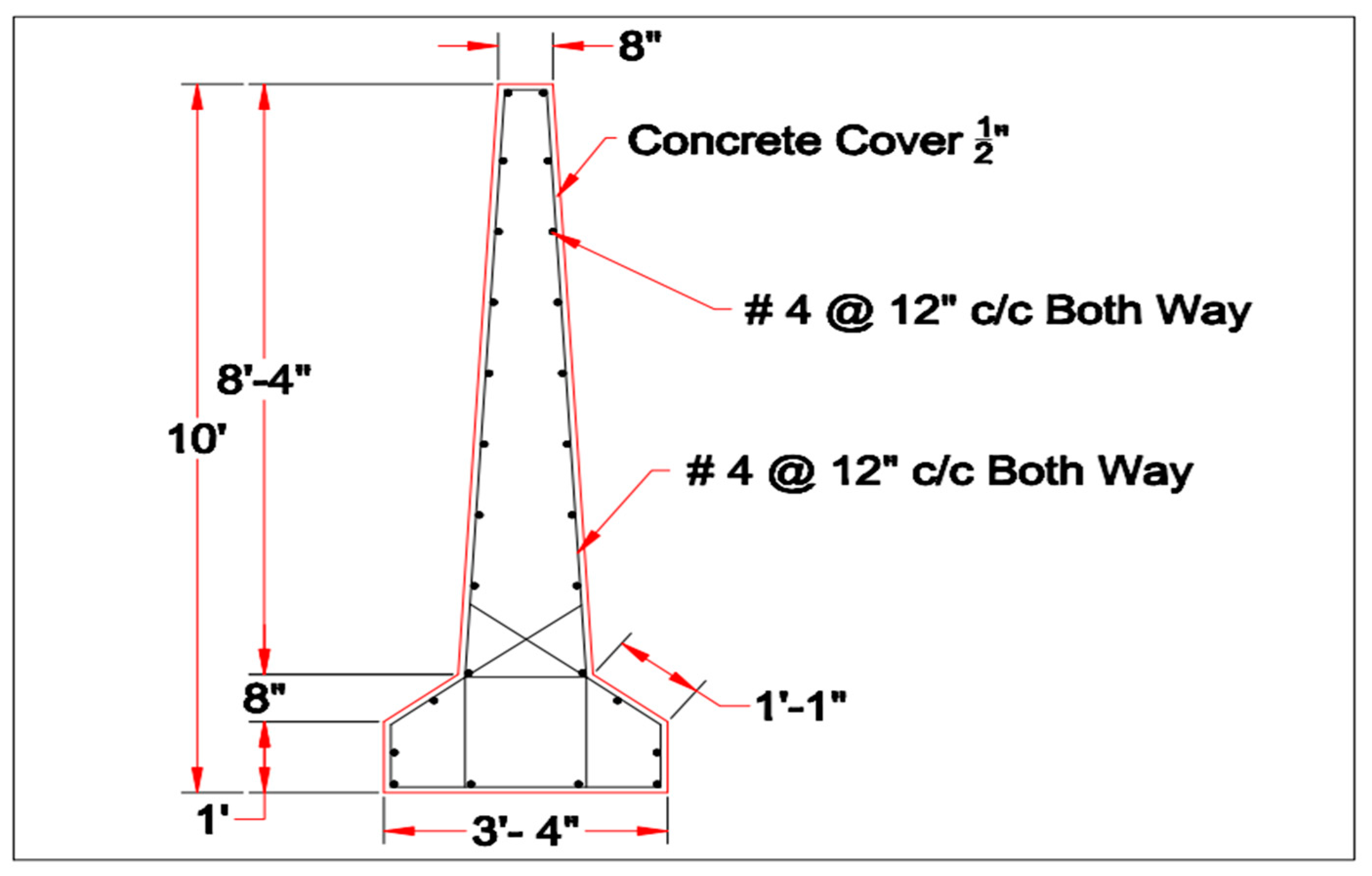
RCC wall panels minimize blast explosion effect [17]. RCC wall panels are positioned in front of the boundary wall side by side. This represents a continuous wall barrier in front of the structure as shown in Figure 1. The RCC wall panel is 10 ft tall, 3 ft wide, 8 inches thick from the top and 3 ft–4 inches thick from the bottom. The effect of soil structure interaction is ignored in this study as being out of scope. Reinforcement detail and existing arrangements are shown in Figure 2 and Figure 3.
2.2. Material Properties
Materials (brick, concrete, mortar, TNT and air) were obtained from the ANSYS AUTODYN library. Properties of brick, concrete, mortar, air and TNT are available in the ANSYS AUTODYN library, however, the mechanical properties of RCC are not directly available in the library. It is very difficult to model concrete and steel separately [18] and requires complete expertise. However, different researchers have worked on it and modified properties have been proposed to produce the effect of reinforcing bars in concrete [18]. Luccioni [18] considered the actual collapse of a four-story building due to a blast explosion in Argentina. He modelled and simulated the same scenario using ANSYS AUTODYN. Modified properties of RCC were used in the model. The results of the actual collapse and numerical simulation compared and validated satisfactorily. The same modified properties of RCC are used in current models. Below Table 1 shows the different properties used in our model for materials.
2.3. Location of Gauges
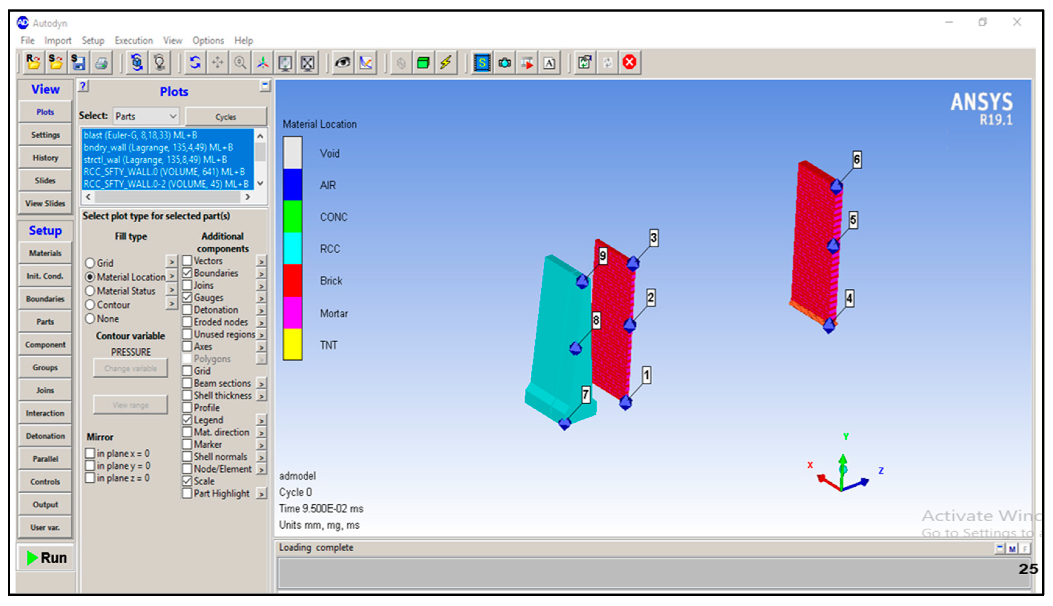
Three gauges are placed at the top, middle and bottom of RCC wall panels, the masonry boundary wall and the masonry structural wall. Displacements of RCC panels and the structural wall have been monitored. All nine gauges placed in the model are shown in Figure 4.
2.4. Techniques Being Used for Strengthening/Retrofitting of Structures against Blast Loading
Extensive research has been carried out to strengthen the existing structures [19]. Due to the large dynamic loading, structural members fail, and casualties/injuries occur. Different improvement techniques are being used to enhance the efficacy of structures against blast loading. The following are some of the techniques used for the retrofitting of the existing structures, for improving its resistance against blast and also improving the overall integrity of the structure [20].
- Aramid fiber reinforced plastics (AFRP) [5]
- Fiber reinforced polymers (FRP) [6]
- Ultra-high performance fiber reinforced concrete [7]
- Glass fiber reinforced polymers [8]
- Carbon fiber reinforced polymers [9]
- Polyurethane elastomers [10]
- Steel jacketing [11]
- Strain hardening cementations composites [12]
- Steel plates [13]
- Glass curtain walls [14]
- FRP composites [19]
- Use of GFRP [21]
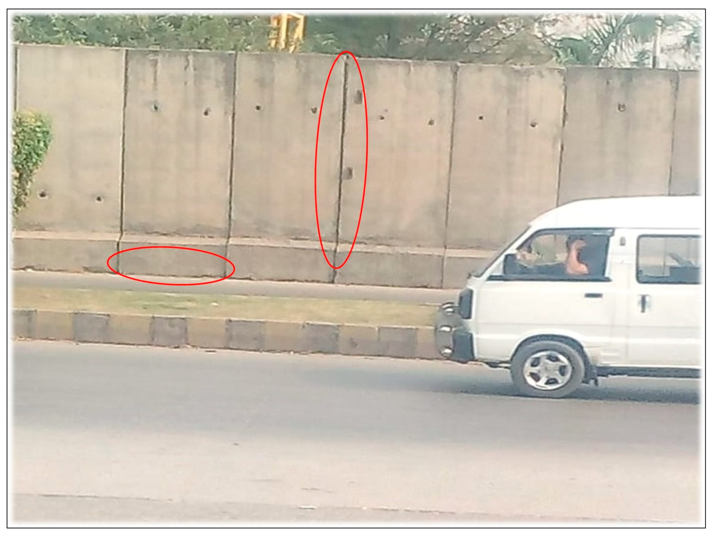
2.5. Weaknesses Observed in Existing Arrangements
Following weakness have been observed as shown in Figure 5:
- The base of the RCC wall panel is not fixed
- Intermediate space between RCC wall panels
- RCC wall panels not designed for blast loading
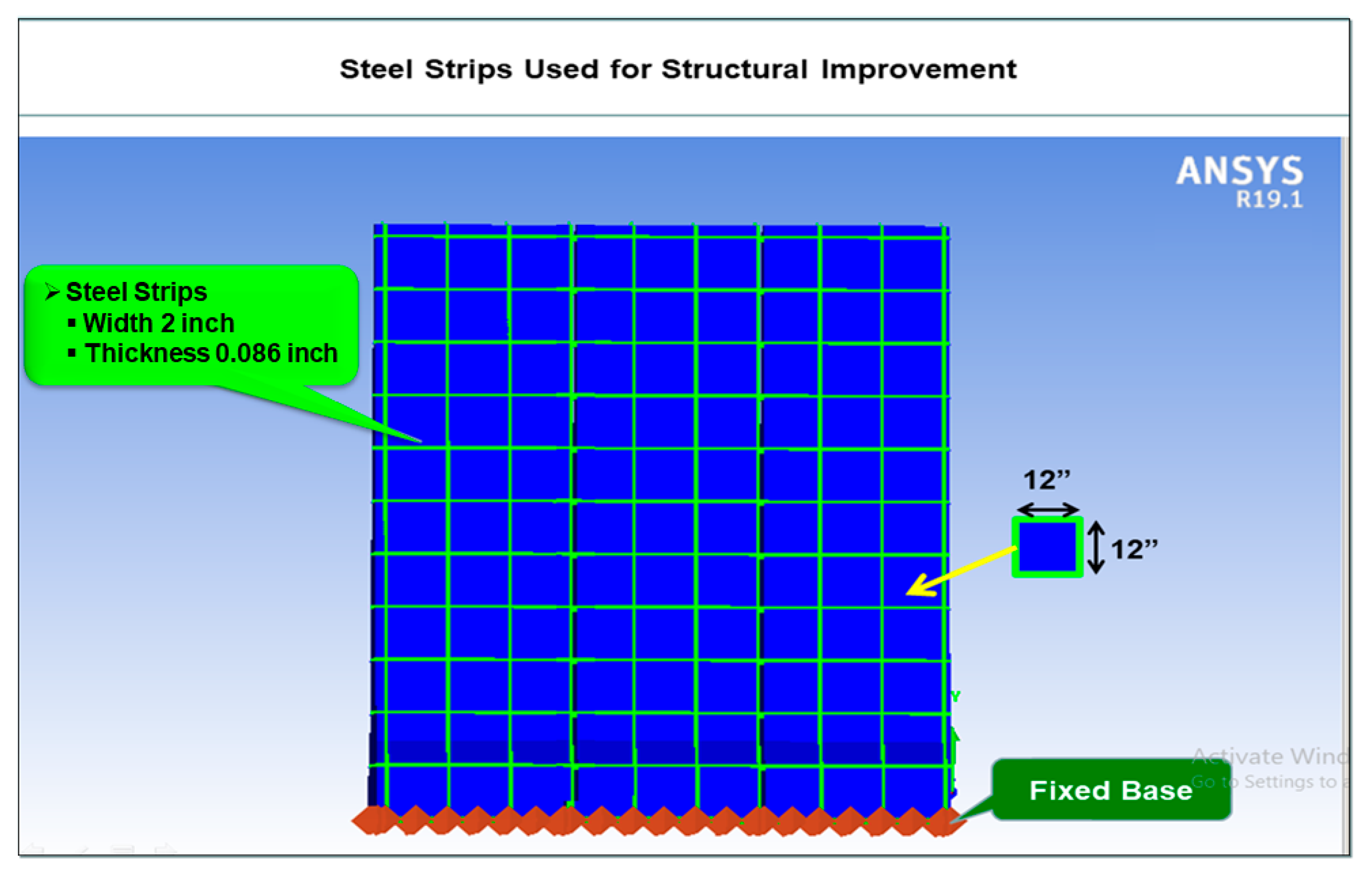
2.6. The Technique Used for Improvement of the Existing Structure against Blast Loading
Strengthening of existing structures using the steel strips technique is being used to improve its resistance against blast loading and to improve the overall integrity of the structure. This technique is more economical, easier to install and more effective in comparison to all other available retrofitting techniques for TNT charge of up to 100 kg. The details are shown in Figure 6. A probabilistic risk assessment (PRA) has been carried out to predict risk of an explosive charge weight and its placement. The blasts occurred in front of important installations which are summarized below:
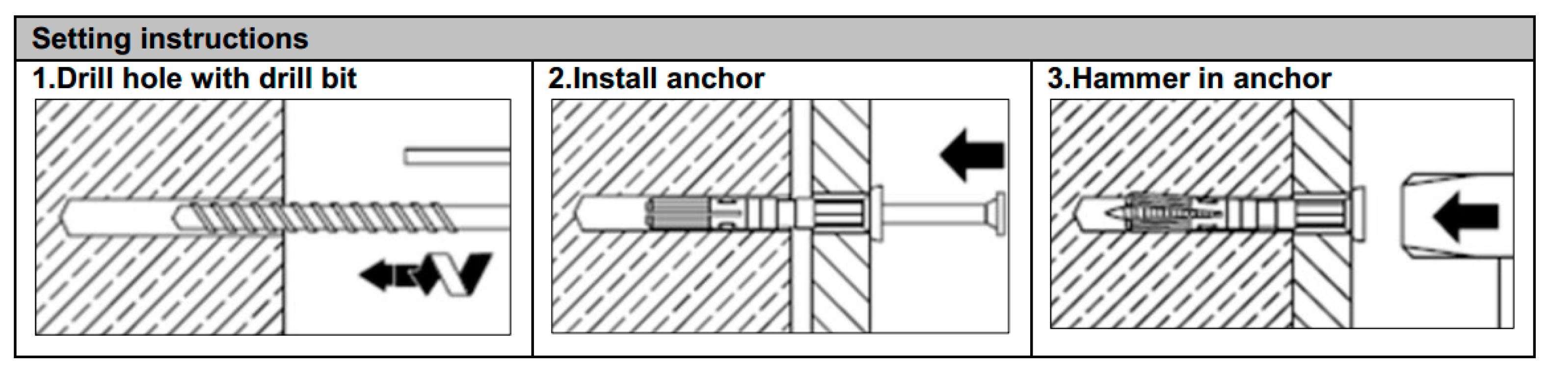
After thorough study and analysis of the terrorist activities related data of the last decade [24] shown in Table 2, two charge weights have been selected, that of 50 kg and 100 kg. The contact between concrete and steel strips is fixed using anchors. The effect of soil structure interaction is ignored in this study, being out of scope [25]. Detailed procedure for the installation of anchors is shown in Figure 7.
- Drill hole with drill bit
- Install anchor
- Hammer in anchor
3. Results and Discussions
A total of two charge weights have been simulated, that of 50 kg TNT and 100 kg TNT. Furthermore, two TNT charge locations were considered, one at the face of RCC wall panels and the other at a distance of 10 ft. Analysis of the existing arrangement has been carried out using ANSYS AUTODYN [26]. After providing external steel strips as strengthening, analysis was performed again for the same charge weight and locations. The comparison of the blast scenario results, before and after the improvement technique against blast loading, is shown in succeeding paragraphs.
3.1. Displacement Time Relationship
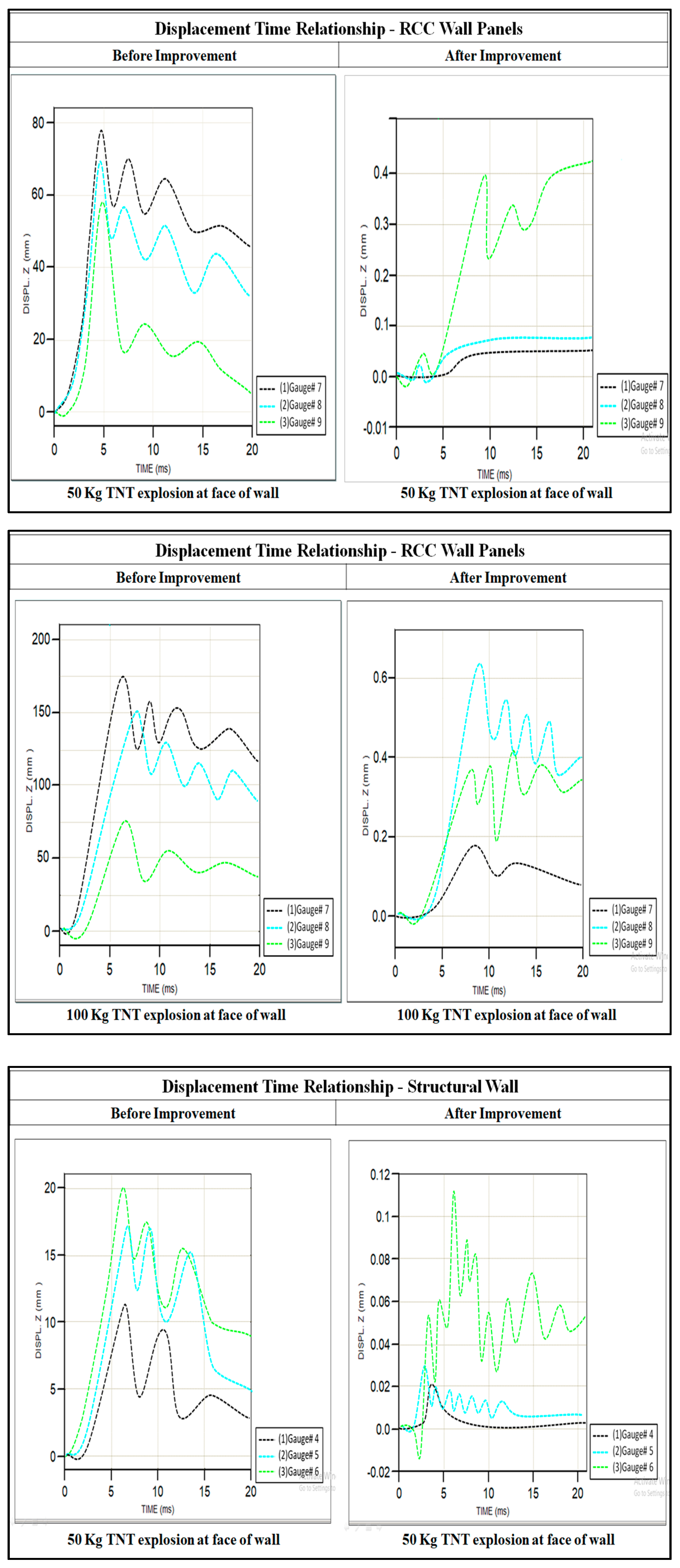
3.1.1. Case I: Explosion at Face of RCC Wall Panels
Figure 8 shows the comparison of the displacement–time relationship before and after the improvement of RCC wall panels. It is evident from the analysis that as the TNT charge weight increases, displacements also increase. Before improvement of an existing structure, the maximum displacement of the RCC wall panel was found at gauge #7 (base of the wall) whereas maximum displacement of the structural wall was found at gauge #6 (top of the wall). The non-fixity of the base and the intermediate spacing between panels provides easy access to pass the blast wave and damage the target. To minimize the effect of the blast, the steel strips were used as a strengthening technique which restricts z-direction movement. It also acts as a protection barrier and does not allow the blast wave to pass. It can be seen from the results that the use of steel strips as a strengthening technique significantly reduces displacements. It is pertinent to mention that displacement mainly reduces due to the use of steel strips as it has restricted vertical and horizontal movement of RCC wall panels. Displacements have been significantly reduced after the use of steel strips as shown below:
- For 50 kg TNT explosion, displacement of RCC wall panel reduces from 78 mm to 0.42 mm
- For 100 kg TNT explosion, displacement of RCC wall panel reduces from 175 mm to 0.62 mm
- For 50 kg TNT explosion, displacement of structural wall reduces from 20 mm to 0.11 mm
- For 100 kg TNT explosion, displacement of structural wall reduces from 41 mm to 0.14 mm
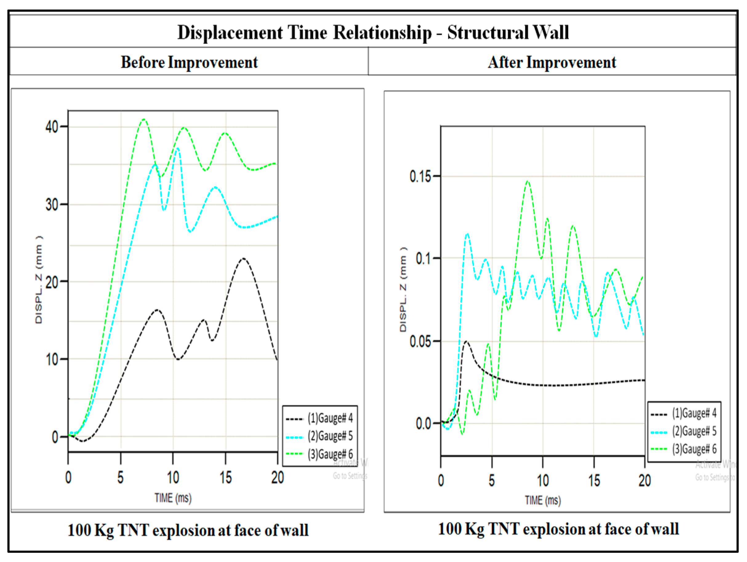
3.1.2. Case II: Explosion at Distance of 10 ft from RCC Wall Panels
Figure 9 shows a comparison of displacement–time relationship when an explosion occurs at a distance of 10 ft from the face of RCC wall panels. It has been found that displacement decreases as the standoff increases. Use of steel strips as a strengthening technique significantly reduces displacements.
- For 50 kg TNT explosion, displacement of RCC wall panels reduces from 48 mm to 0.18 mm
- For 100 kg TNT explosion, displacement of RCC wall panels reduces from 76 mm to 0.42 mm
- For 50 kg TNT explosion, displacement of structural wall reduces from 15 mm to 0.07 mm
- For 100 kg TNT explosion, displacement of structural wall reduces from 17 mm to 0.12 mm
RCC wall panels are not anchored/fixed to the ground and have a horizontal space between panels of 1 inch to 5 inches. Due to non-fixity, displacements up to 175 mm have been noted. Use of steel strips as a strengthening technique significantly reduced displacements up to 99% for TNT charge of up to 100 kg.
3.2. Pressure Time History
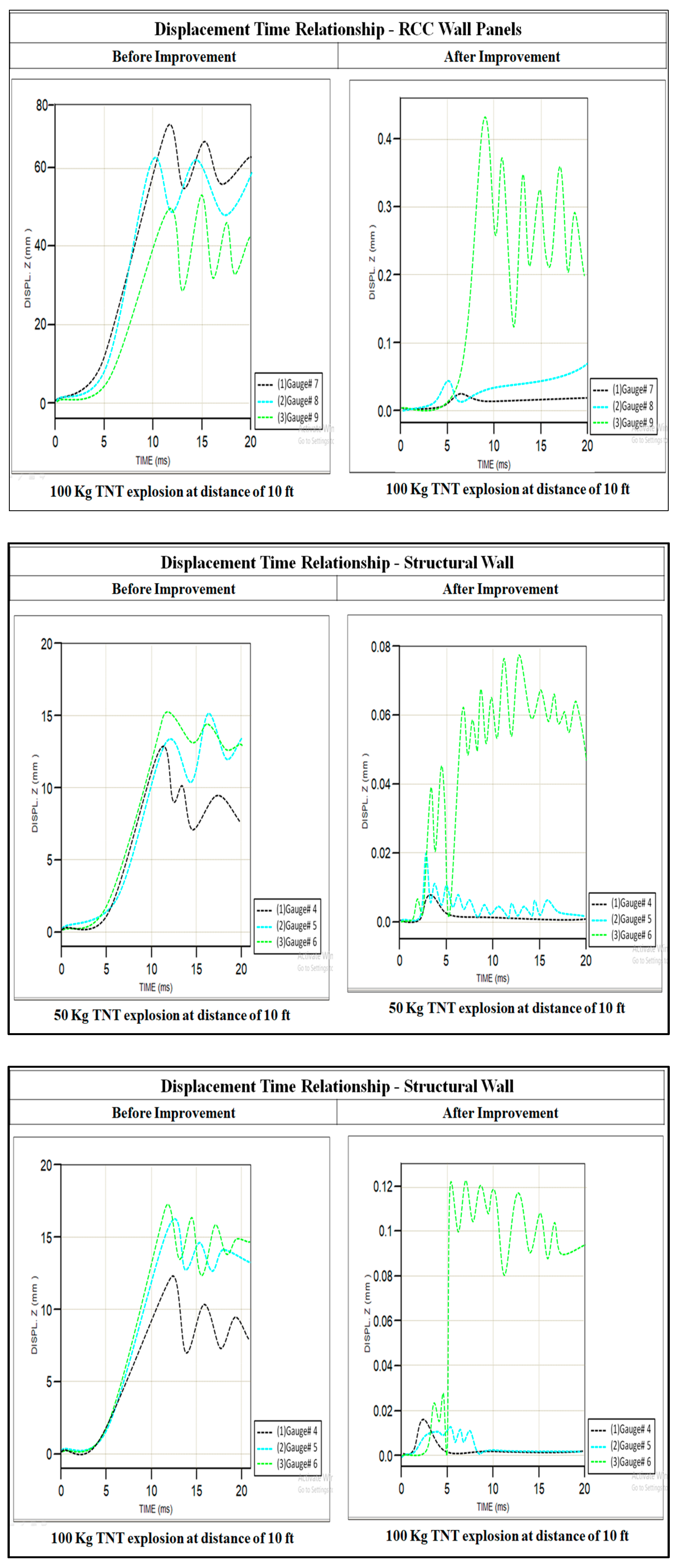
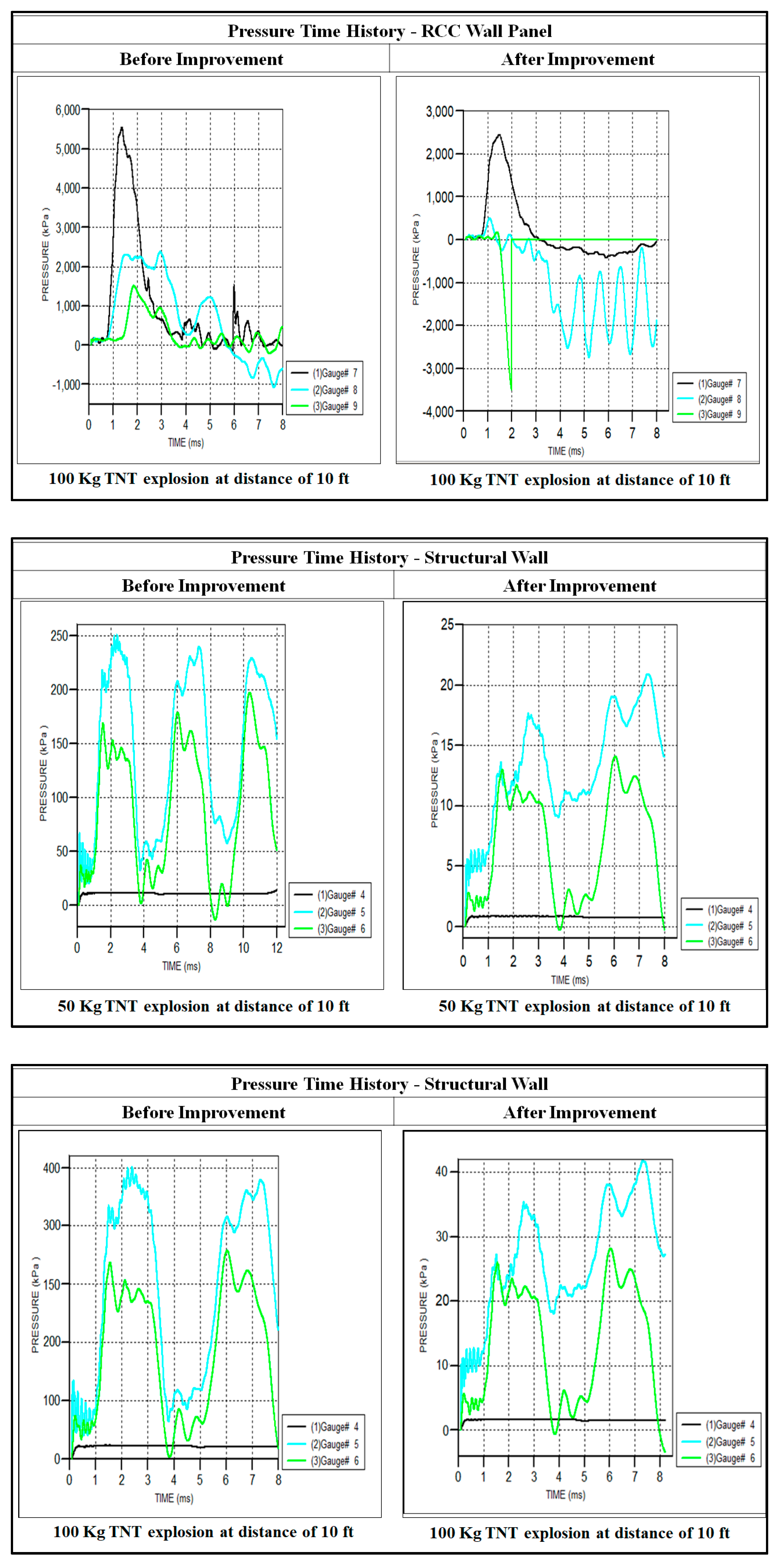
3.2.1. Case I: Explosion at Face of RCC Wall Panels
Figure 10 shows a comparison of the pressure time history when an explosion occurs at the face of RCC wall panels. It is evident that the distribution of pressure is not uniform and varies with each millisecond. Blast resistant structures cannot be designed for an equivalent static pressure or lateral loads. However, the area under the pressure time curve can be taken into account for the design of these structures. It has been observed that the pressure was maximum at gauge #7, at the base of RCC wall panels and minimum at gauge #4, at the base of the structural wall. Use of steel strips as a strengthening technique has worked effectively and pressure values recorded after structural improvement are considerably reduced as compared to existing arrangements (without improvement technique) of RCC wall panels. However, negative pressure was amplified due to the interaction of the blast wave with the solid surface of RCC wall panels. After improvement, pressure values were significantly reduced at the structural wall due to the restriction of the blast wave propagation.
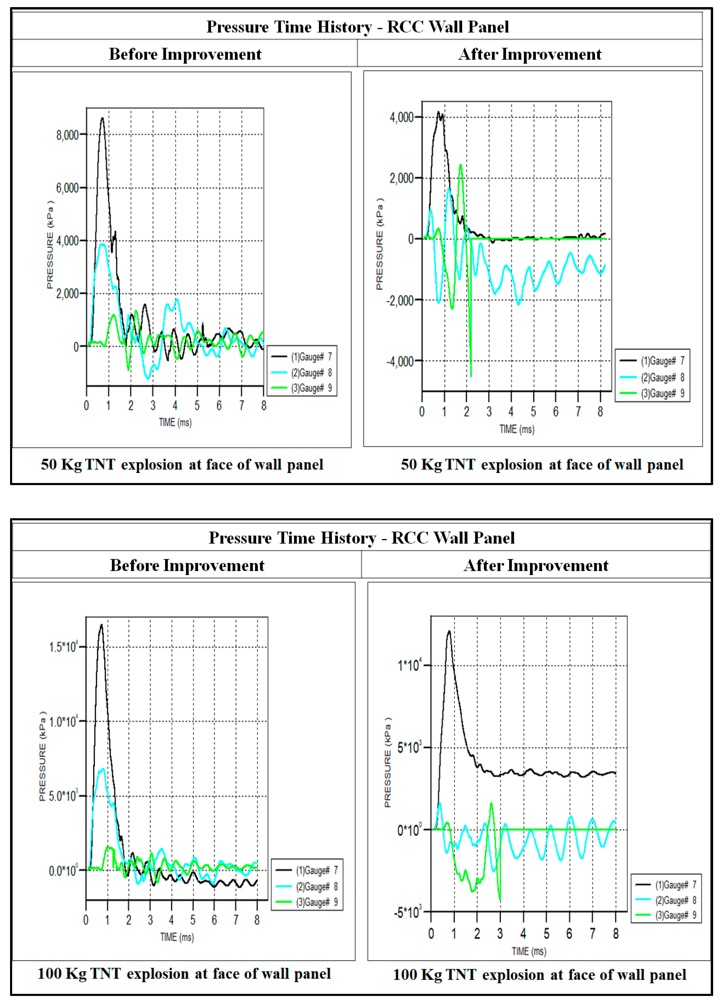
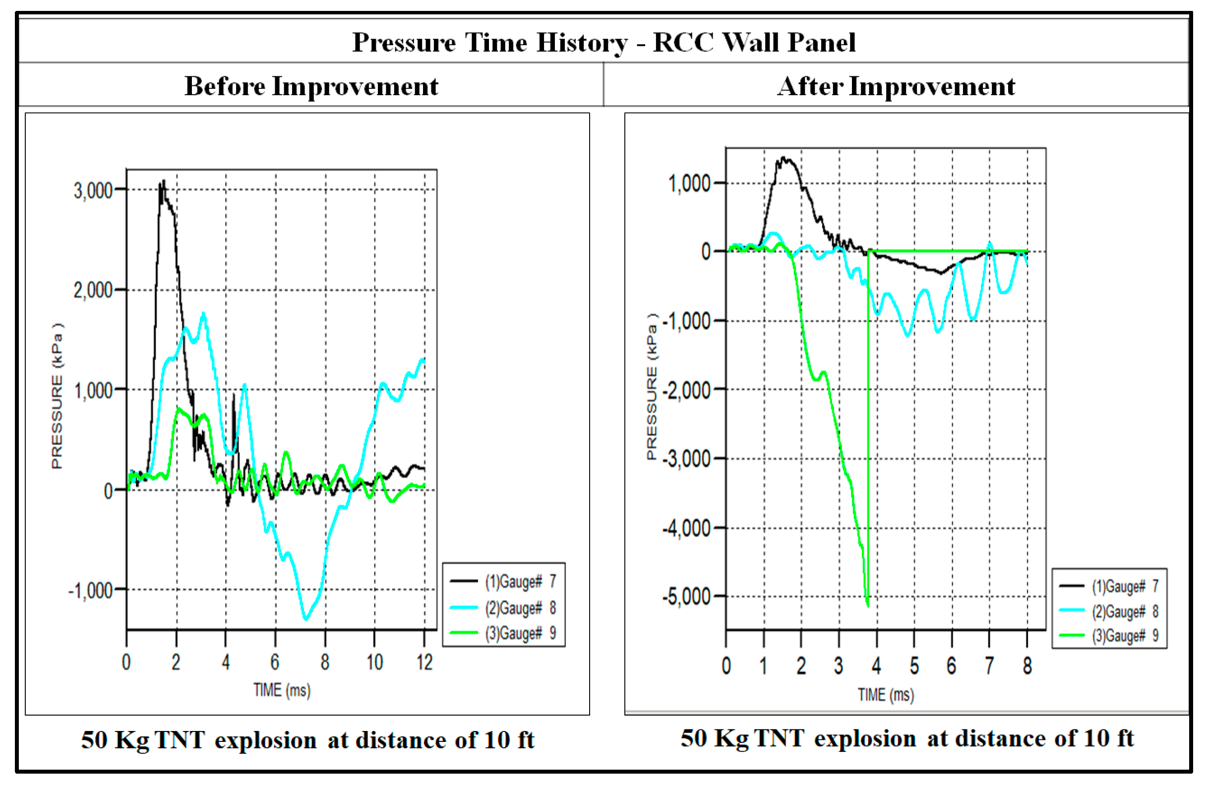
3.2.2. Case II: Explosion at Distance of 10 ft from RCC Wall Panels
Figure 11 shows a comparison of pressure–time relationship when an explosion occurs at a distance of 10 ft from the face of RCC wall panels.
Results obtained from FEM show that with the increase in TNT charge quantity, displacements also increase. Displacement and standoff distance have an inverse relation, i.e., displacement decreases with the increase in standoff distance, having the same TNT charge quantity. Before improvement of the existing structure, maximum displacement of RCC wall panels was found at gauge #7 (base of wall) whereas maximum displacement of the structural wall was found at gauge #6 (top of wall). It has also been noticed that the non-fixity of base and intermediate spacing between panels provides easy access to pass the blast wave and damage the structural wall. Results also show that steel strips used as a strengthening technique restricts z-direction movement and acts as a protection barrier, by not allowing the blast wave to pass.
4. Conclusions
A numerical study of RCC wall panels placed in front of the building has been conducted to analyze the effect of blast loading. An existing arrangement of an important military installation, NESCOM Hospital, Faqir Api Road, Islamabad, Pakistan has been selected where RCC wall panels were used as a protection barrier against blast loading. ANSYS AUTODYN software has been used to simulate the model. Analysis has been carried out and pressure was observed to be maximum at the base of RCC wall panels and minimum at the base of the structural wall. With the increase in standoff distance, pressure values decreased, and the distribution of pressure was also not uniform. Weaknesses of existing arrangements have also been identified. Existing RCC wall panels were not designed for blast loading. These are also not anchored/fixed to the ground and have a horizontal space between panels of 1 inch to 5 inches.
A significant number of RCC panels are placed in front of many installations. Therefore, in order to make them more effective, remedial measures should be taken to sort out the existing flaws by using steels strips as a strengthening technique. From the results, it is concluded that in addition to existing strengthening techniques, steel strips are one of the most feasible and locally suitable techniques for strengthening existing structures as it significantly enhances the blast performance of structures. It has significantly reduced z-direction displacements and pressures. Steel strips have been found effective up to 100 kg TNT explosion and displacements against explosion almost diminished. Hence the effect of the blast explosion would be transferred to the building. RCC wall panels, placed in front of buildings, can be strengthened by using steel strips against blast explosion up to 100 kg. Peak pressures of TNT charge up to 100 kg obtained from simulations may be taken as a guideline for designers.
Despite all the bright and encouraging perspectives of this research work, there are certain limitations. Firstly, blast scenarios could be infinite. Secondly, this strengthening technique effectively works up to 100 kg TNT charge. The effect of blast on structures also depends on blast material used, type of the explosive and on its placement. Thirdly, the software used here in this study requires special training and expertise to run.
There are also some important recommendations which need to be catered to in future. Primarily, results obtained by this research work are required to be checked by performing experimental testing. Secondly, existing RCC wall panels need to be strengthened by using steel strips, as it provides maximum protection against blast loading. Peak pressures obtained from the simulation of different blast scenarios may be taken as a guideline for the design of RCC wall panels.
Author Contributions
Conceptualization, M.U. and S.H.F.; methodology, R.K. and S.H.F.; software, R.K.; validation, S.H.F. and M.U.; formal analysis, R.K.; investigation, R.K. and M.U.; resources, M.U.; data curation, R.K.; Writing—Original Draft preparation, R.K.; Writing—Review and Editing, S.H.F. and M.U.; visualization, S.H.F.; supervision, M.U.; project administration, M.U.
Funding
This research received no external funding.
Acknowledgments
Authors acknowledge the administrative support provided by National University of Sciences and Technology, Islamabad 44000, Pakistan.
Conflicts of Interest
The authors declare no conflict of interest.
References
- Ding, C.; Ngo, T.; Mendis, P.; Lumantarna, R.; Zobec, M. Dynamic response of double skin façades under blast loads. Eng. Struct. 2016, 123, 155–165. [Google Scholar] [CrossRef]
- Yao, S.; Zhang, D.; Chen, X.; Lu, F.; Wang, E. Experimental and numerical study on the dynamic response of RC slabs under blast loading. Eng. Fail. Anal. 2016, 66, 120–129. [Google Scholar] [CrossRef]
- Li, J.; Wu, C.; Hao, H.; Wang, Z.; Su, Y. Experimental investigation of ultra-high performance concrete slabs under contact explosions. Int. J. Impact Eng. 2016, 93, 62–75. [Google Scholar] [CrossRef] [Green Version]
- Codina, R.; Ambrosini, D.; de Borbon, F. Experimental and numerical study of a RC member under a close-in blast loading. Eng. Struct. 2016, 127, 145–158. [Google Scholar] [CrossRef]
- Kong, X.; Qo, X.; Gu, Y.; Lawam, I.A.; Qu, Y. Numerical evaluation of blast resistance of RC slab strengthened with AFRP. Constr. Build. Mater. 2018, 178, 244–253. [Google Scholar] [CrossRef]
- Chundawat, T.S.; Vaya, D.; Sini, N.K.; Varma, I.K. Blast mitigation using FRP retrofitting and coating techniques. Polym. Compos. 2018, 39, 1389–1402. [Google Scholar] [CrossRef]
- Aoude, H.; Frederic, P.D.; Burell, R.P.; Saatcioglu, M. Behavior of ultra-high performance fiber reinforced concrete columns under blast loading. Int. J. Impact Eng. 2015, 80, 185–202. [Google Scholar] [CrossRef]
- Jacques, E.; Lloyd, A.; Asce, A.M.; Imbeau, P.; Palermo, D.; Asce, A.M. GFRP-Retrofitted Reinforced Concrete Columns Subjected to Simulated Blast Loading. J. Struct. Eng. 2015, 141, 04015028. [Google Scholar] [CrossRef]
- Chen, L.; Fang, Q.; Fan, J.; Zhang, Y.; Hao, H.; Liu, H. Responses of masonry infill walls retrofitted with CFRP, steel wire mesh and laminated bars to blast loadings. Adv.Struct. Eng. 2014, 17, 817–836. [Google Scholar] [CrossRef]
- Somarathna, H.; Raman, S.N.; Badri, K.H.; Mutalib, A.A. Mechanical characterization of polyurethane elastomers: For retrofitting application against blast effects. In Proceedings of the 3rd Conference on Smart Monitoring, Assessment and Rehabilitation of Structures (SMAR2015), Antalya, Turkey, 7 September 2015. [Google Scholar]
- Codina, R.; Ambrosini, D.; de Borbón, F. Alternatives to prevent the failure of RC members under close-in blast loadings. Eng. Fail. Anal. 2016, 60, 96–106. [Google Scholar] [CrossRef]
- Adhikary, S.D.; Chandra, L.R.; Christian, A.; Ong, K.C.G. SHCC-strengthened RC panels under near-field explosions. Constr. Build. Mater. 2018, 183, 675–692. [Google Scholar] [CrossRef]
- Chen, J.; Teng, J. Anchorage strength models for FRP and steel plates bonded to concrete. J. Struct. Eng. 2001, 127, 784–791. [Google Scholar] [CrossRef]
- Jie, G.; Guoqiang, L. Dynamic analysis of glass curtain walls with protective films subjected to blast loading. Int. J. Struct. Eng. 2012, 3, 160–169. [Google Scholar] [CrossRef]
- Lin, X.; Zhang, Y.; Hazell, P.J. Modelling the response of reinforced concrete panels under blast loading. Mater. Des. (1980–2015) 2014, 56, 620–628. [Google Scholar] [CrossRef]
- Yusof, M.A.; Rosdi, R.N.; Ismail, A.; Yahya, M.A.; Peng, N.C. Simulation of reinforced concrete blast wall subjected to air blast loading. J. Asian Sci. Res. 2014, 4, 522–533. [Google Scholar]
- Smith, P. Blast walls for structural protection against high explosive threats: A review. Int. J. Prot. Struct. 2010, 1, 67–84. [Google Scholar] [CrossRef]
- Luccioni, B.; Ambrosini, R.; Danesi, R. Analysis of building collapse under blast loads. Eng. Struct. 2004, 26, 63–71. [Google Scholar] [CrossRef]
- Buchan, P.; Chen, J. Blast resistance of FRP composites and polymer strengthened concrete and masonry structures—A state of the art review. Compos. Part B Eng. 2007, 38, 509–522. [Google Scholar] [CrossRef]
- Rasheed, A.; Farooq, S.H.; Usman, M.; Hanif, A.; Khan, N.A.; Khushnood, R.A. Structural reliability analysis of superstructure of highway bridges on China-Pakistan Economic Corridor (CPEC): A case study. J. Struct. Integr. Maint. 2018, 3, 197–207. [Google Scholar] [CrossRef]
- Razaqpur, A.G.; Tolba, A.; Contestabile, E. Blast loading response of reinforced concrete panels reinforced with externally bonded GFRP laminates. Compos. Part B Eng. 2007, 38, 535–546. [Google Scholar] [CrossRef]
- Farooq, H.; Usman, M.; Mehmood, K.; Malik, M.S.; Hanif, A. Effect of Steel Confinement on Axially Loaded Short Concrete Columns. IOP Conf. Ser. Mater.Sci.Eng. 2018, 414, 012026. [Google Scholar] [CrossRef]
- Farooq, S.H.; Ilyas, M.; Ghaffar, A. Technique for strengthening of masonry wall panels using steel strips. Asian J. Civil Eng. (Build. Hous.) 2006, 7, 621–638. [Google Scholar]
- Terrorist Activities in Last Decade and Accessed. Available online: http://www.pakistanbodycount.com (accessed on 10 August 2018).
- Khan, B.L.; Farooq, H.; Usman, M.; Butt, F.; Khan, A.Q.; Hanif, A. Effect of soil–structure interaction on a masonry structure under train-induced vibrations. Proc. Inst. Civil Eng. Struct. Build. 2018. [Google Scholar] [CrossRef]
- ANSYS AUTODYN. Available online: https://www.ansys.com (accessed on 26 August 2018).
Figure 1.
Blast protection wall panels.

Figure 2.
Reinforcement detail of reinforced cement concrete (RCC) wall panels.

Figure 3.
Existing arrangements of blast protection wall panels.

Figure 4.
Gauges placed at the top, middle and bottom.

Figure 5.
Weaknesses observed in existing arrangements.

Figure 6.
Steel strips modelled as a strengthening technique for structural improvement.

Figure 7.
Procedure for installation of anchors.

Figure 8.
Comparison of TNT explosions at the face of RCC wall panels.


Figure 9.
Comparison of TNT explosions at a distance of 10 ft from RCC wall panels.


Figure 10.
Comparison of TNT explosions at the face of RCC wall panels.


Figure 11.
Comparison of TNT explosions at a distance of 10 ft from RCC wall panels.


Table 1.
Properties of material used in ANSYS AUTODYN.
| Properties of air | |
| State equation | Ideal gas |
| γ | 1.41 |
| Reference density | 1.225E-03 g/cm3 |
| Reference temperature | 2.882E + 02 oK |
| Specific heat (C.V.) | 7.173 + 02 J/kg K |
| Properties of reinforced concrete | |
| State equation | Linear |
| Reference density | 2.750 g/cm3 |
| Bulk modulus | 3.527E+07kPa |
| Strength model | Von Mises |
| Shear modulus | 1.220E+07 kPa |
| Elastic limit | 1.000E+04kPa |
| Failure criteria | Principal stresses |
| Failure stress | 1.000+04kPa |
| Properties of masonry | |
| State equation | Linear |
| Reference density | 2.400E+00 g/cm3 |
| Bulk modulus | 7.800E+06 kPa |
| Strength model | Mohr Coulomb |
| Shear modulus | 2.6E+06 kPa |
| Failure criteria | Principal stresses |
| Failure tension | 1.000+03 kPa |
Table 2.
Important blasts in last decade.
| Ser | Location | TNT (Kilograms) |
|---|---|---|
| 1 | U.S. Consulate Karachi | 70 |
| 2 | U.S. Consulate Karachi | 100 |
| 3 | Parachinar, Pakistan | 50 |
| 4 | Charbagh, Swat Valley, KPK | 60 |
| 5 | Police Checkpoint Peshawar | 80 |
| 6 | Orakzai Agency, FATA | 95 |
| 7 | Khyber Bazaar, Peshawar | 30 |
| 8 | Timergara, Lower Dir | 75 |
| 9 | Lakki Marwat District, KPK | 79 |
| 10 | Khyber Agency, FATA | 56 |
| 11 | Ghalanai, Mohmand Agency, FATA | 50 |
© 2019 by the authors. Licensee MDPI, Basel, Switzerland. This article is an open access article distributed under the terms and conditions of the Creative Commons Attribution (CC BY) license (http://creativecommons.org/licenses/by/4.0/).
Share and Cite
MDPI and ACS Style
Khan, R.; Farooq, S.H.; Usman, M. Blast Loading Response of Reinforced Concrete Panels Externally Reinforced with Steel Strips. Infrastructures 2019, 4, 54. https://0-doi-org.brum.beds.ac.uk/10.3390/infrastructures4030054
AMA Style
Khan R, Farooq SH, Usman M. Blast Loading Response of Reinforced Concrete Panels Externally Reinforced with Steel Strips. Infrastructures. 2019; 4(3):54. https://0-doi-org.brum.beds.ac.uk/10.3390/infrastructures4030054
Chicago/Turabian StyleKhan, Rizwan, Syed Hassan Farooq, and Muhammad Usman. 2019. "Blast Loading Response of Reinforced Concrete Panels Externally Reinforced with Steel Strips" Infrastructures 4, no. 3: 54. https://0-doi-org.brum.beds.ac.uk/10.3390/infrastructures4030054