Structural Evaluation of Variable Gauge Railway


1
Department of Mechanical Engineering, Kunsan National University, 558 Daehak-ro, Gunsan 54140, Korea
2
Railroad Safety Research Team, Korea Railroad Research Institute, 176 Railroad Museum St., Uiwang-si 16105, Korea
3
Department of Naval Architecture and Ocean Engineering, Kunsan National University, 558 Daehak-ro, Gunsan 54150, Korea
*
Author to whom correspondence should be addressed.
Infrastructures 2020, 5(10), 80; https://0-doi-org.brum.beds.ac.uk/10.3390/infrastructures5100080
Submission received: 13 September 2020
/
Revised: 27 September 2020
/
Accepted: 28 September 2020
/
Published: 1 October 2020
(This article belongs to the Section Infrastructures and Structural Engineering)
Abstract
:In the Eurasian railway network, a different gauge length is used across several countries. A railroad variable gauge allows railway vehicles in rail transport to travel across a gauge break caused by two railway networks with differing track gauges. The variable gauge railway consists of the bogie system to change the length of the wheel shaft and the gauge changing railroad track. Thus, it is important to assess the structural performance of the variable gauge system. In this study, as a performance improvement subject of the variable gauge bogie and railroad, a structural analysis using dynamic finite element calculation was performed to evaluate the reliability and life cycle of the release system and the variable gauge railway. First, the contact pressure and structural stress of the release disk and the release rail were calculated, which provided the wear condition and fatigue life prediction of variable gauge components. Second, a structural analysis of the gauge stabilization rail after the gauge release was executed. The maximum principal stress was evaluated to guarantee the required service life of the stabilization rail section. For the operational safety of the variable gauge system, the operation conditions and maintenance requirements of the variable gauge railway were proposed.
1. Introduction
A railway network is comprised of several different gauge lengths for historical reasons: narrow gauge, standard gauge, and broad gauge. Due to this difference in gauge length, conventional trains cannot run on the same track, and consequently, passengers are forced to transfer at intermediate junctions [1]. To avoid transportation difficulties and the cost of different gauge tracks on the trains, a variable gauge system is an efficient solution applied in some countries, such as in the Eurasian railroad network [2,3]. This system effectively replaces time-consuming tasks such as transferring freight, replacing individual wheels and axles, truck exchange, transporters, or transporter flatcars because the systems mentioned above are both time consuming and very costly. Kondo [4] introduced a novel traction control system of the gauge changing train, which can run through two different gauge sections. The Spanish Talgo train, which is operating between Spain and France, is known for its variable system, enabling it to switch between broad (1668 mm) and standard European gauges [5].
Recently a variable gauge wheelset system installed in the bogie was developed and the fatigue strength of the system was investigated [6,7]. A life cycle cost model was developed to assess the effectiveness of a variable gauge system [8]. Several factors can influence fatigue life, including loading history, stress state, strain rate, and temperature, and can lead under certain conditions (like low temperature) to brittle fracture [9,10]. Failure of a component can have catastrophic consequences; therefore, the study and prediction of railroad failure can prevent loss of life and property damage [11,12,13]. Fatigue cracking is caused by cyclic loads, although the resultant stress level is substantially below the material’s yield strength [14]. Besides fatigue analysis, other factors need to be considered to avoid loss of life and property damage, such as wear and friction. Friction occurs between two contact surfaces in relative motion, whereas wear is the phenomenon of mechanical and chemical damage that affects the quality of the materials in contact with each other [15,16]. Wear of system components is often a critical factor influencing the product service life. In addition, the overhead electric wire interaction [17] to transmit the electricity to the railway vehicle and the vehicle system dynamics [18] to reduce longitudinal oscillations in passenger trains need to be addressed in the design of the wheelset system.
In this paper, to quantitively evaluate the life of the variable gauge railway, dynamic finite element analysis using Abaqus was executed for the release disk and the release rail in Section 2. Between contracting parts of the disk and the rail, there is limiting criteria for contact pressure to avoid wear problems using the Archard formula [19,20]. Based on the finite element simulation and the wear criteria of the contacting surface, the safe operating velocity and the fatigue issues of the release dick in the variable gauge system were proposed with an emphasis on the lubrication of the contact surface to minimize friction and to reduce mechanical wear. In Section 3, the fatigue life of the grooved rail in the variable gauge railway during the gauge changing operation is estimated from the load history of the multi-body dynamic analysis. Through fatigue life assessment by structural stress analysis, the designed release rail and the grooved rail in the variable gauge system are guaranteed to be safe in the sense of metal fatigue if continuous maintenance procedures such as surface lubrication and inspection are applied adequately.
2. Structural Analysis of Variable Gauge Release Rail
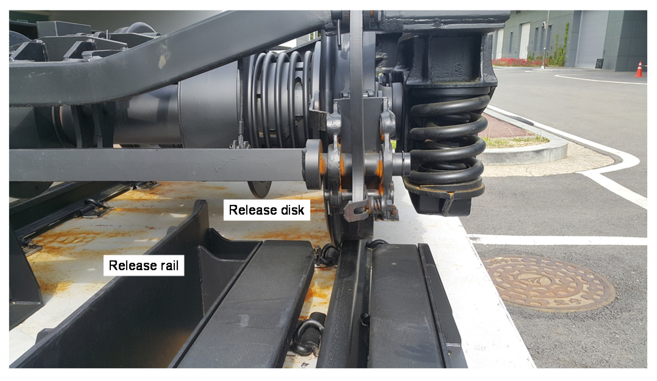
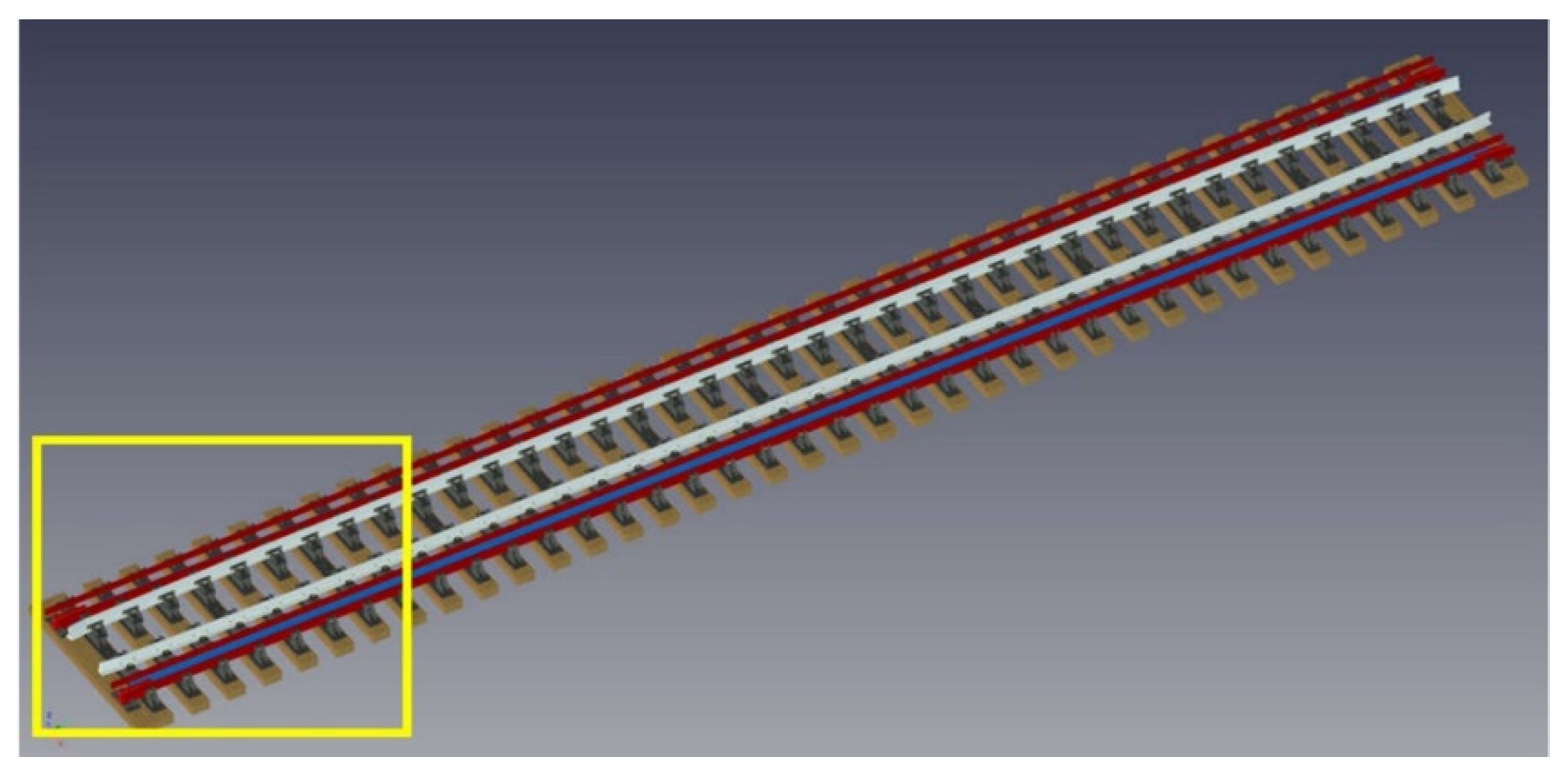
To perform the gauge transformation from the standard-gauge railway with 1435 mm track gauge to broad gauge railway with 1520 mm track gauge, the release disk is installed on the bogie gauge, and the locked state of the bogie axle is released by the operating principle that the release disk is pushed in contact with the release rail when the bogie is advancing. The variable gauge system of the release rail and the release disk in the unlocking section is illustrated in Figure 1. The unlocking section of the variable gauge railroad of 2380 mm length is shown in Figure 2.
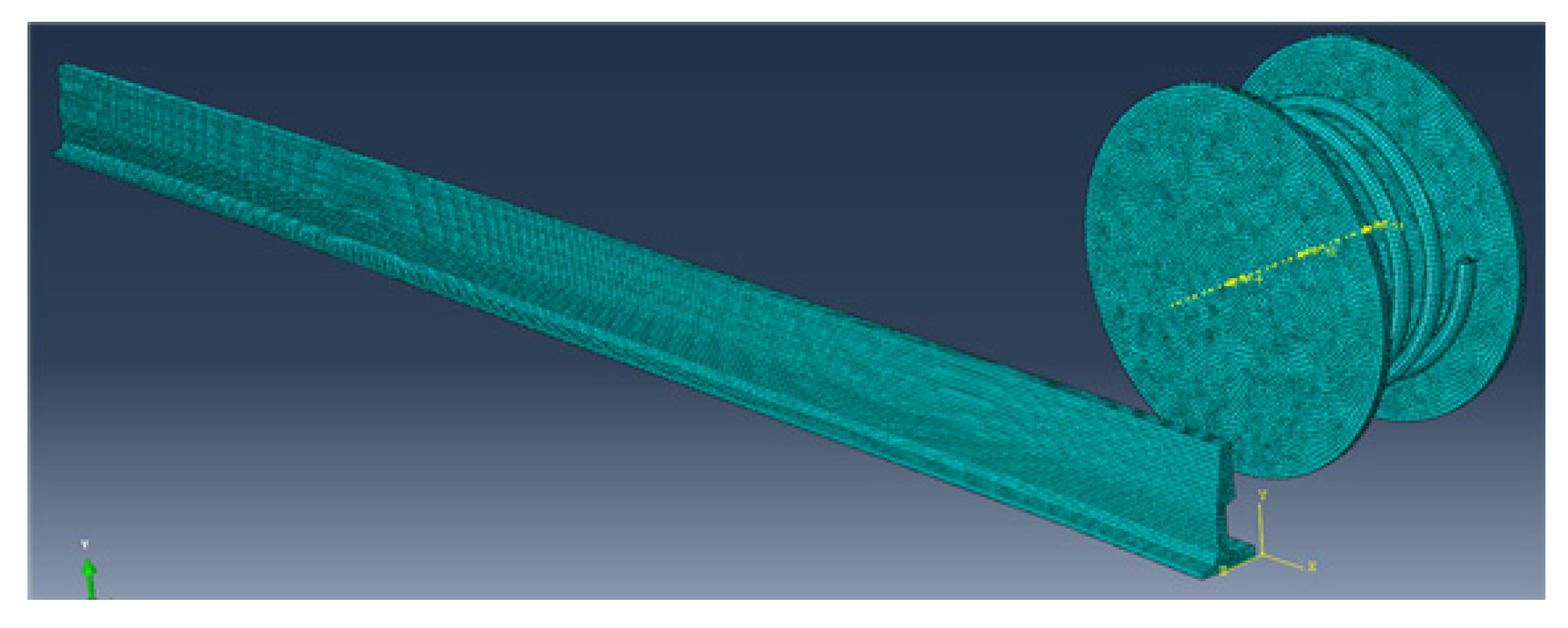
To perform the gauge conversion between standard gauge and broad gauge, a release disk is installed on the bogie axle to unlock the gauge system. As a fixed part, the release rail is installed in the releasing section in Figure 2. The release rail made of SS400 low carbon steel is shown in Table 1. The release disk is made of STS304 stainless steel that has a Young’s modulus of 190 GPa and tensile strength of 520 MPa, as seen in Table 2. For dynamic finite element analysis using Abaqus, the model and mesh are shown in Figure 3. Each model was constructed using a solid hexahedral element, a spring consisting of 16,848 elements, a release disk of 23,752 solid elements, and a release rail of 62,505 solid elements. The mesh convergence was confirmed in all finite element calculations.
2.1. Stress History of Release Rail
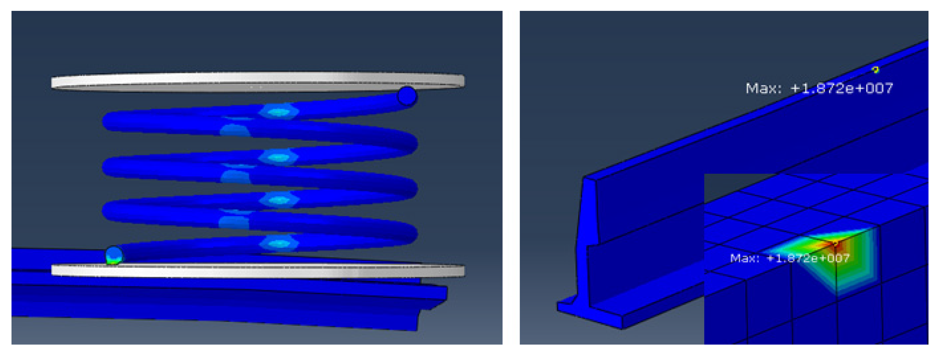
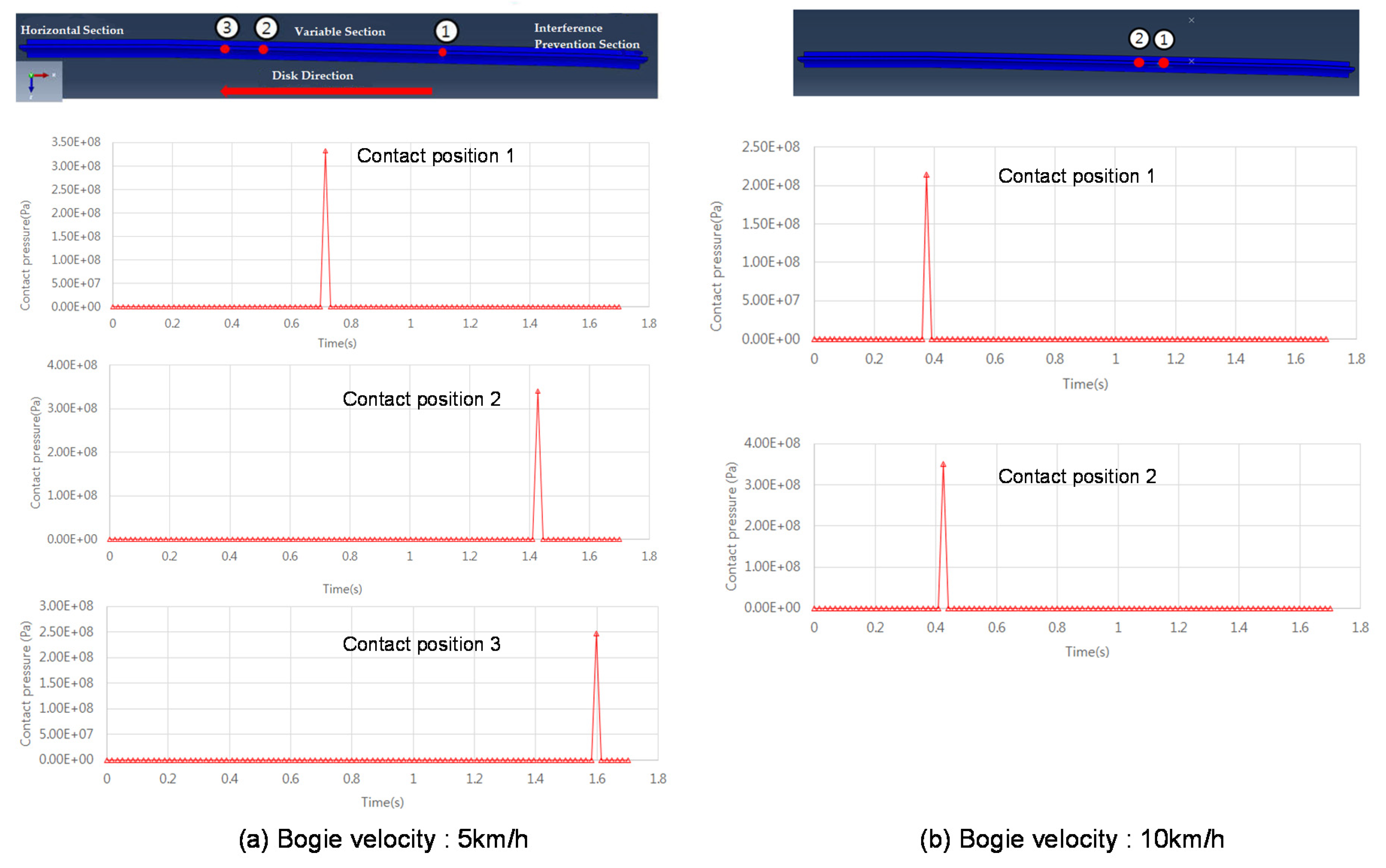
The contact pressure was calculated, and is shown in Figure 4, when the release firstly comes into contact with the release rail at a velocity of 5 km/h and a pressure value of initial contact of about 18.7 MPa at 5 km/h. It takes about 1.7 s for the release disk to reach the horizontal section of the release rail. The contact pressure of the impact area is greater than the yield strength and is presented in detail. For the bogie traveling at a speed of 5 km/h, the contact pressures at three positions exceed the yield strength as high as 350 MPa, and their locations are shown in Figure 5a. For the 10 km/h bogie speed, the contact pressure locations and histories are shown in Figure 5b.
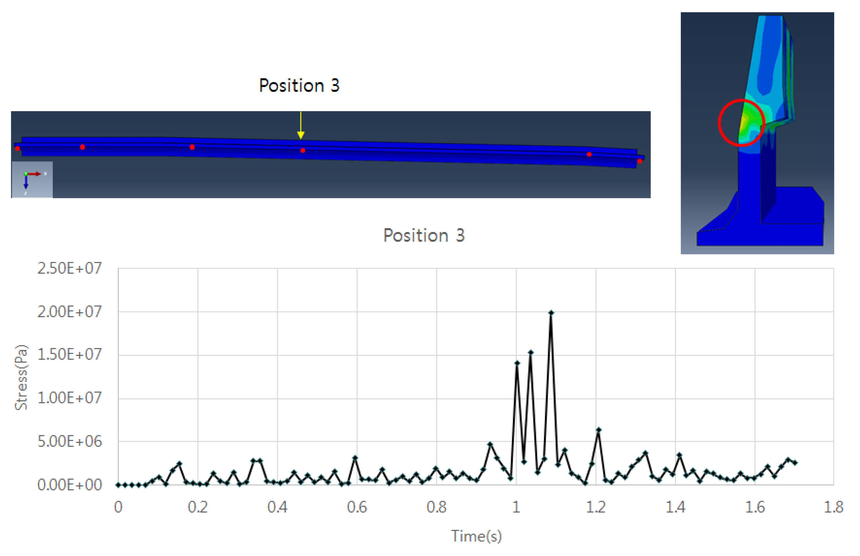
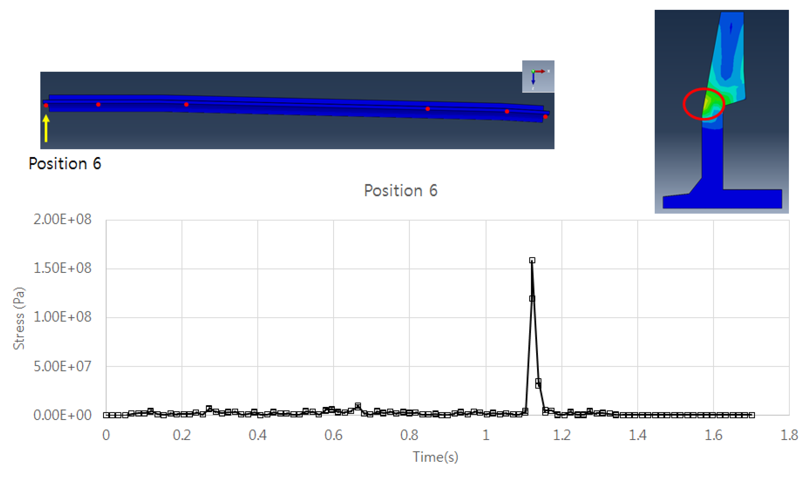
Just because the contact pressure of the impactor is greater than the yield strength, it does not mean immediate damage to the contact location, but it means that there is the possibility of fatigue damage such as local plastic deformation or long-term wear of cracks. When the bogie moves at 5 km/h and 10 km/h, other high-stress locations are identified; their stress histories are shown in Figure 6 and Figure 7, respectively. From the stress histories, the maximum von Mises stress is 20 MPa for 5 km/h bogie speed and 160 MPa for 10km/h bogie speed.
2.2. Life Cycle Prediction
The wear of the contact area may be indicated by a value of contact pressure and the slip velocity, as shown in Table 3. This data refers to the information and indication of the wear of railway tracks carried out by the Bombardier company, which quantitatively evaluates the value of the wear factor using the Archard wear formula [18]. In the performed analysis, the contact pressure between the release disk and the release rail is considered to be a mild wear condition for the 350 MPa at the speed of 5 km/h (1.39 m/s), which does not cause any particular problems in the area of operation of the variable track gauge system.
Since the wear is related to uncertainties such as the shape of the contact surface and the lubrication conditions, then applying a lubricant between the release disk and the release rail can prevent problems related to wear. Therefore, referring to [21] we stress the importance of applying the appropriate lubricant for the release rail. In the dry case, the wear rate is higher than 8.0 µg/m/mm2 but decreases to a value smaller than 1.0 µg/m/mm2 when lubricated. Performed numerical calculations indicated only mild wear happens between the release rail and the release disk; the application of lubricants will minimize the uncertainties in real engineering applications. The applying schedule of lubricants is another subject to be addressed by the real maintenance and inspection of rail conditions.
The results of the analysis were used to assess fatigue loads and predict the life cycle of the release rail. Morishita et al. [12] represented the fatigue line by the correlation of the equivalent stress amplitude vs. the number of fatigue cycles. For SS400 low-carbon steel, which is the material of the release rail, the fatigue endurance limit, σe, was about 175 MPa. If the yield strength, σy, is 245 MPa for SS400, the Soderberg fatigue criteria in Equation (1) is considered conservatively.
where σm and σa are the mean stress and the alternating stress amplitude, respectively.
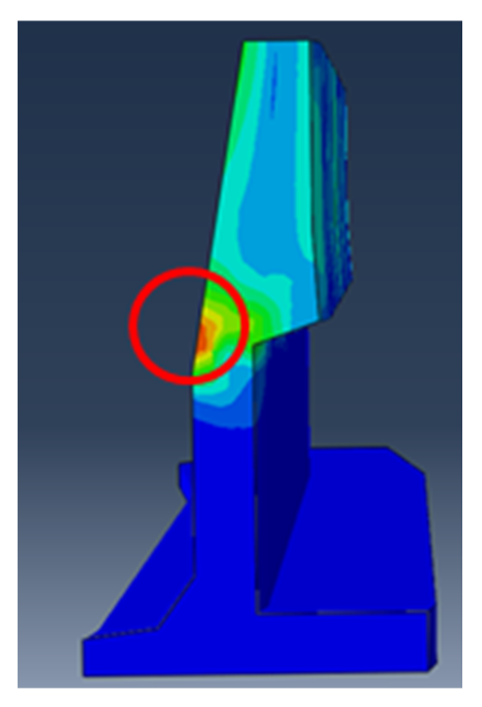
When calculating the fatigue life using the Soderberg criteria, it is common to use the principal stresses. Alternatively, a signed von Mises theory can be utilized for fatigue evaluation under the condition that the biaxiality ratio, σ2/σ1 is less than zero [22]. Given the von Mises stress level of 20 MPa at a velocity of 5 km/h, it can be confirmed that the variable gauge release rail is free from fatigue damage when the bogie is traveling at 5 km/h in the variable gauge section, as the stress level is much lower than the fatigue endurance limit of 175 MPa. To minimize uncertainties in fatigue life, it is recommended to reinforce the area at the neck of the release rail, shown in Figure 8, where a large stress concentration occurs.
3. Structural Analysis and Fatigue Life Prediction of the Rail in the Stabilization Section
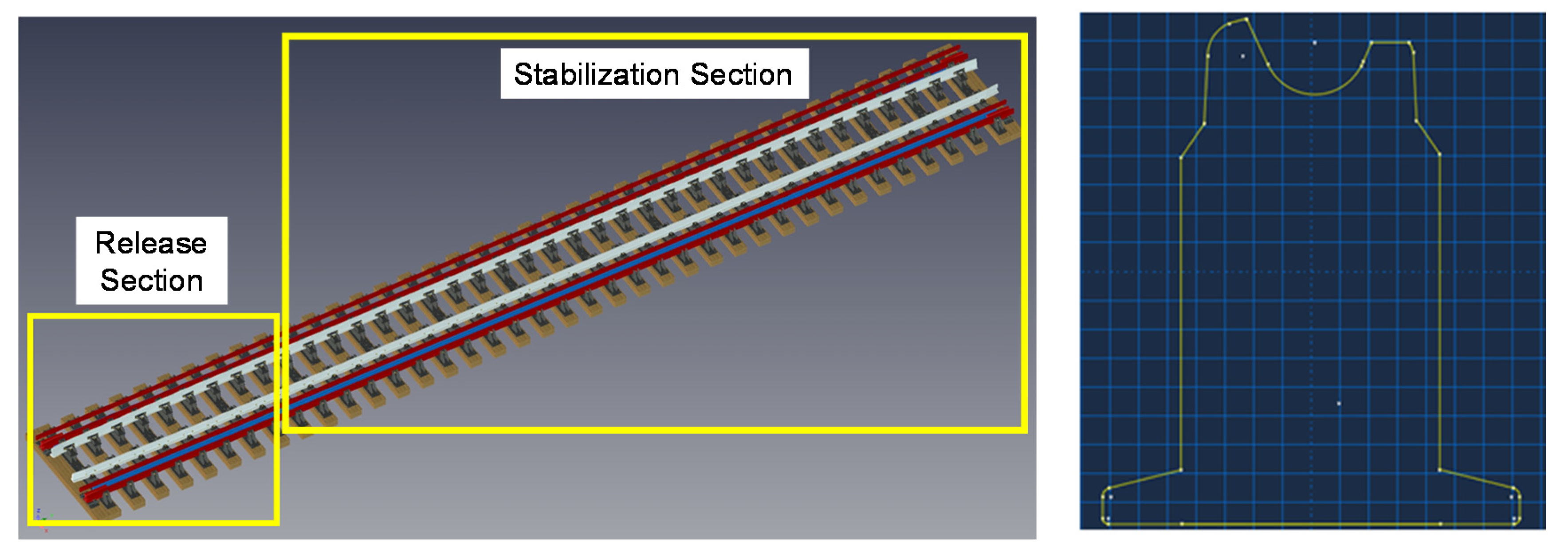
After the variable gauge system in the bogie releases, it passes through the stabilization track section of 12,260 mm, which changes the wheel distance of the bogie from standard gauge railway to broad gauge. The floor plan of this variable gauge railway is as follows. The variable gauge rail is made of a groove-shaped section that is different in shape from the normal rail to support the wheel when the gauge widens, and its cross-section is shown in Figure 9.
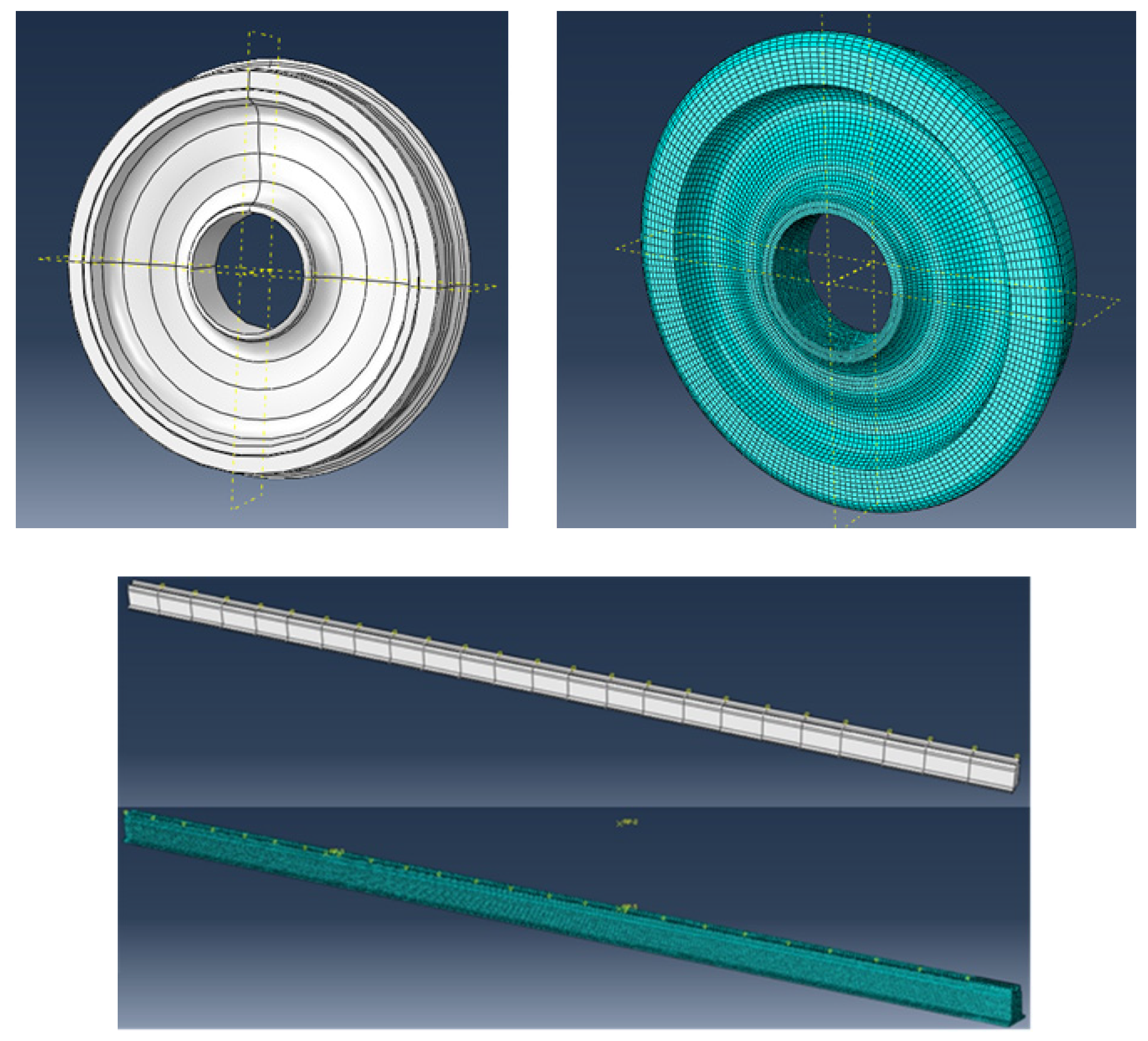
The railway track in the release section and the stabilization section uses the same material of UIC 60 rail. It has high strength steel properties: a tensile strength of 880 MPa and an yield strength of 580 MPa. For the finite element analysis in the stabilization rail section, the wheel and the variable gauge track of a groove section were modeled. The generated mesh used a solid hexagonal element with 53,879 elements applied for wheels and 180,600 elements for the stabilization rail, as shown in Figure 10.
3.1. Input Loads by Multi-Body Dynamics
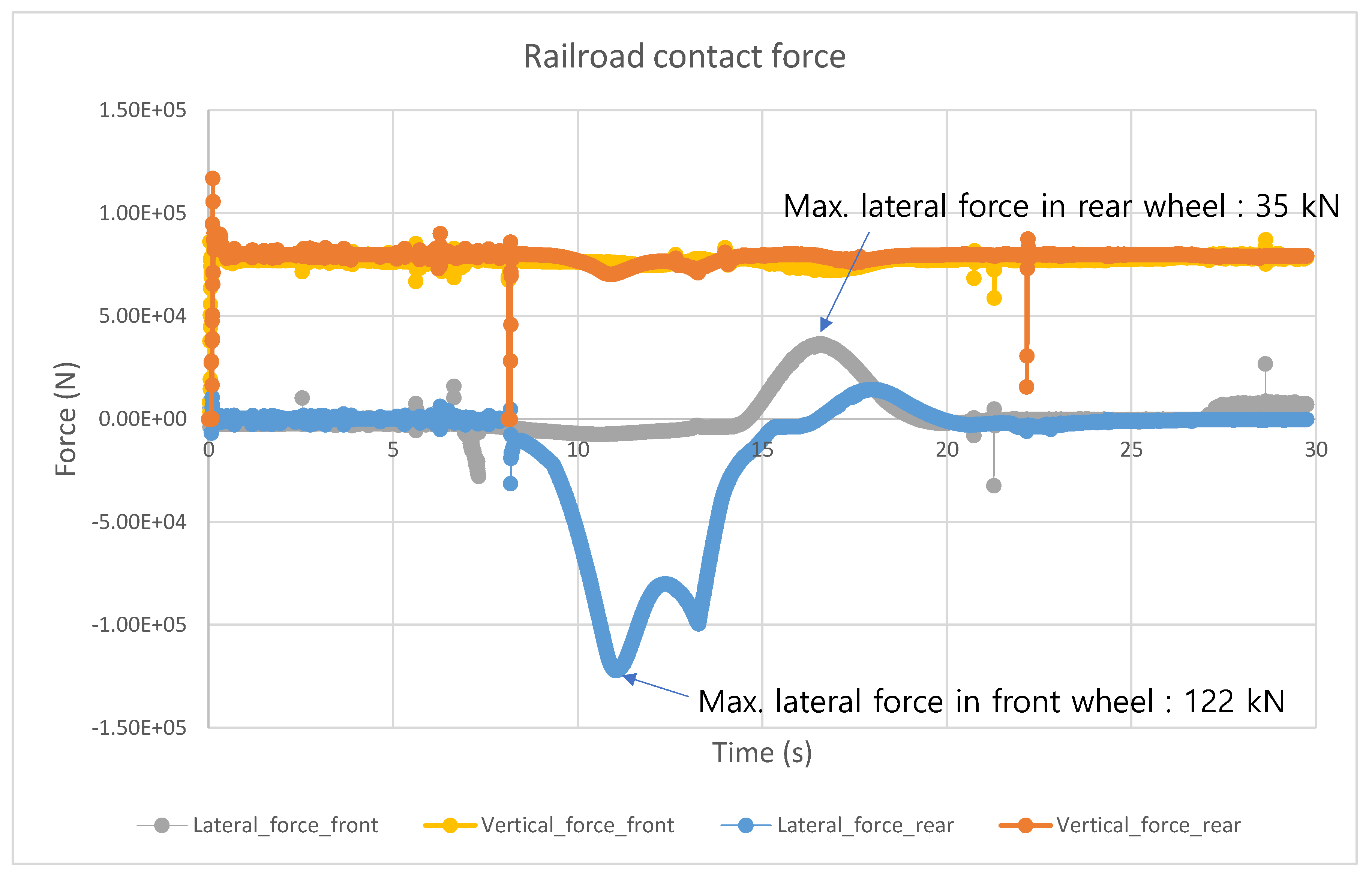
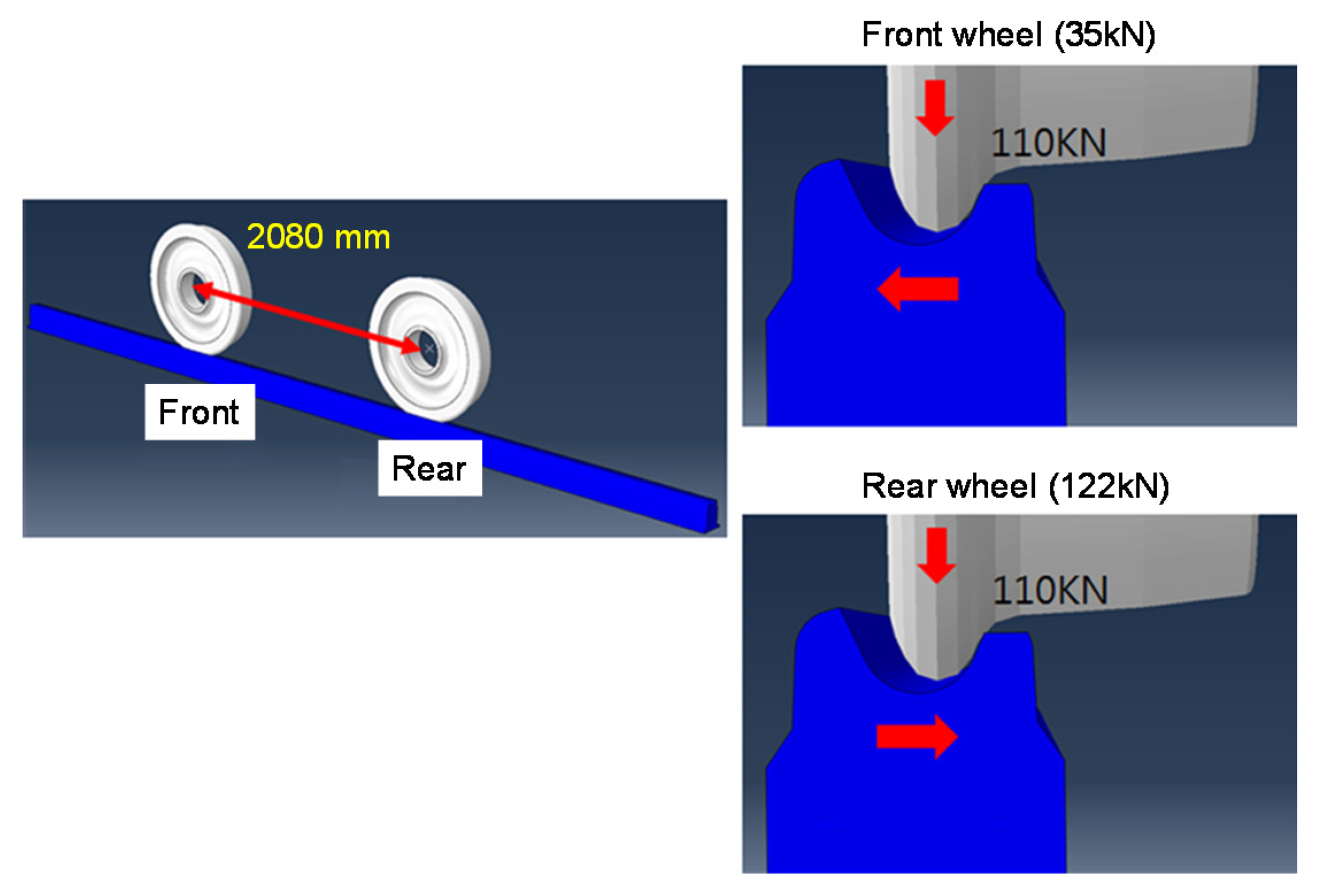
The multi-body dynamic analysis is carried out when the bogie passed the overall gauge changing section, shown in Figure 9, at a speed of 5 km/h. The acting and reacting force results between the wheel and the rail obtained from the multi-body dynamic analysis of the bogie and the track were used as input loads for the analysis of the grooved rail in the stabilization track. The three-dimensional model and numbering of the multi-body dynamics model are shown in Figure 11, and the time history of contact forces applied to each wheel is shown in Figure 12.
From the contact force histories shown in Figure 12, a vertical load of 85 kN by the weight of the cargo train is applied. In the front wheel, the maximum lateral forces are 35 kN and 122 kN for the front wheel and the rear wheel, respectively. These lateral forces occur due to the lateral imbalance in the stabilization section. From the contact force history, the rear wheel hits the track first, the front wheel reacts, and finally the motion of the bogie is stabilized. For the structural analysis of the track, the maximum lateral loads are taken from the contact force history and 110 kN vertical force in KRL-2012 standard design load for the conservative assessment. The applied load condition is summarized in Figure 13.
3.2. Structural Analysis of the Rail in the Stabilization Section
To verify the effect of the railroad tie as boundary conditions, the quasi-static analysis was carried out for two cases; the first was when the front and rear wheels were located between the railroad ties, and the second was when the wheels were placed on the railroad tie. Due to the slow change rate of contact forces shown in Figure 12, dynamic analysis was not considered here.
1. When both wheels are placed between the railroad ties.
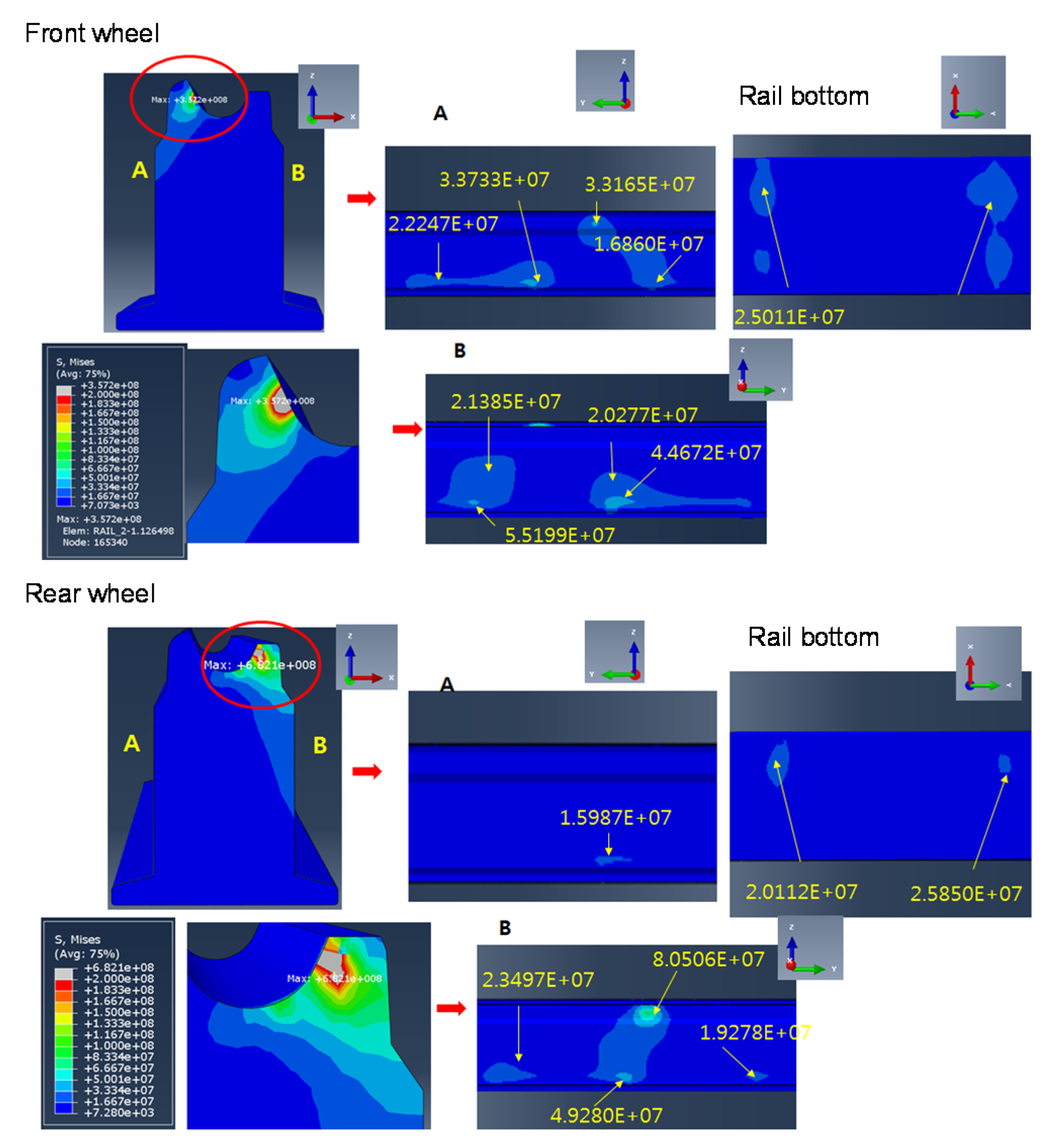
Figure 14 shows the analysis results, in terms of the von Mises stress resulting from the contact between the wheel and the grooved rail. The stress at the contact position by the front wheel and by the rear wheel was 357 MPa and 682 MPa, respectively. The contour plot of von Mises stress by the wheel contract is shown in Figure 14 in detail.
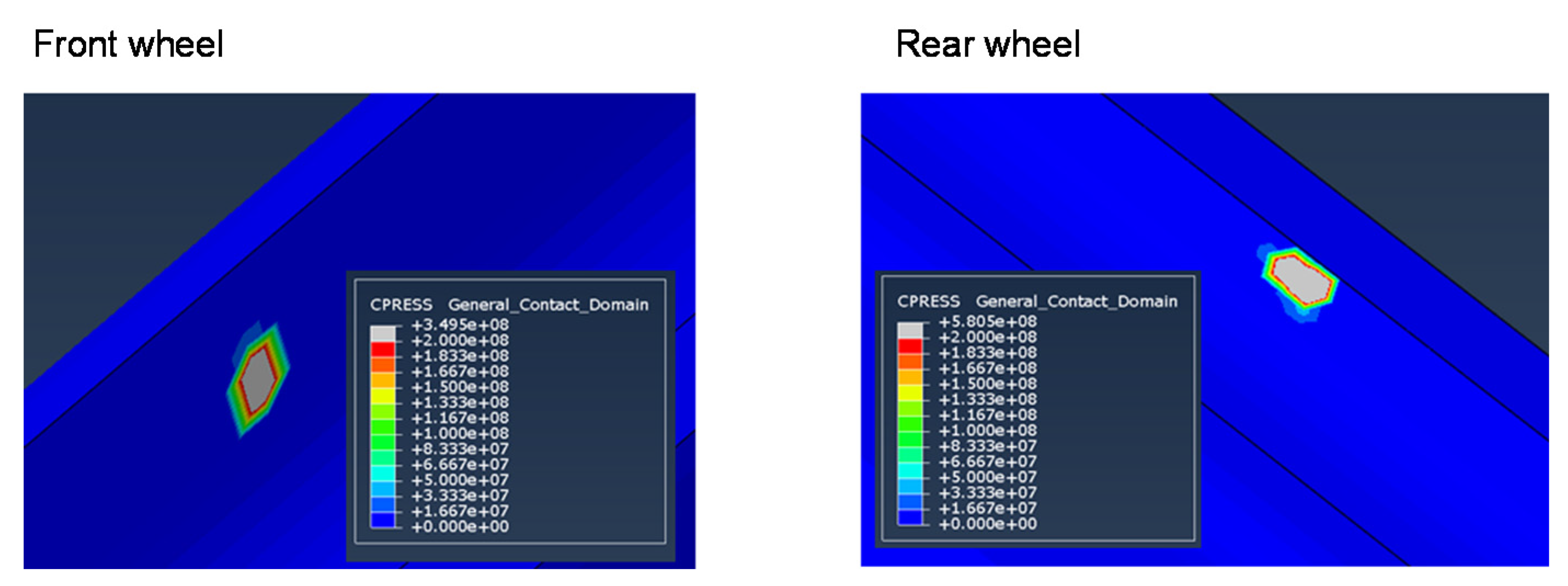
It is important to evaluate the contact pressure between the grooved rail and wheels to analyze the fatigue failure of the component due to wear. Figure 15 shows that the maximum contact pressure by the rear wheel is larger than the maximum contact pressure of the front wheel with the values of 349 MPa and 580 MPa, respectively. As seen in Table 3, this level of contact pressure and the slip velocity of 5 km/h only result in mild wear.
Table 4 shows a summary of the structural analysis when the wheels are placed between the railway ties.
2. When the wheels are on the railroad tie
Figure 16 shows the analysis results, in terms of the von Mises stress resulting from the contact between the wheel and the rail. The stresses at the contact position by the front wheel and by the rear wheel were 357 MPa and 682 MPa, respectively. The contour plot of von Mises stress by the wheel contract is shown in Figure 16 in detail.
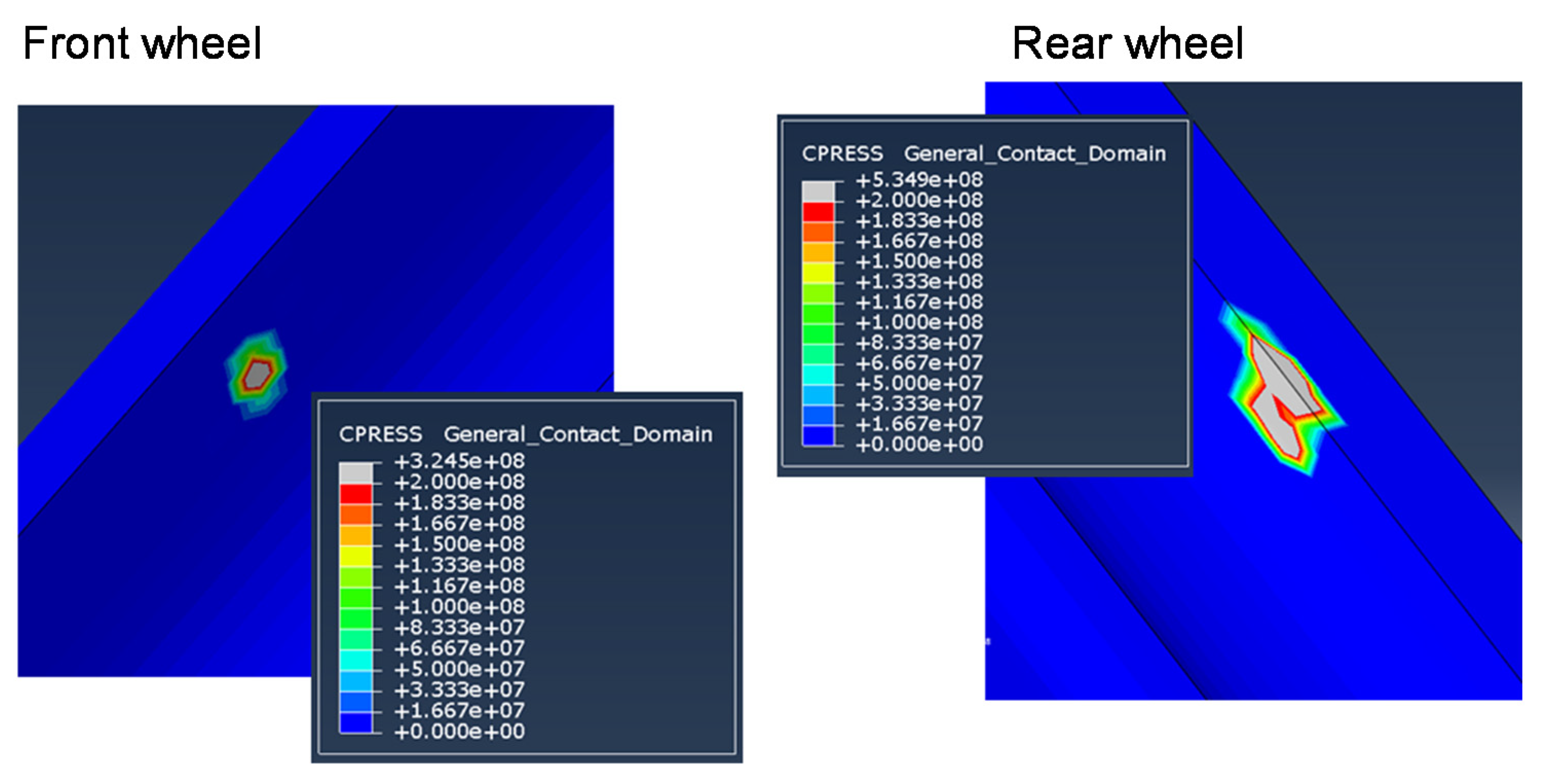
To assess wear possibility by the contract pressure and the slip, the contract pressure at the contract location was evaluated. Figure 17 shows the maximum contact pressure by the rear wheel was larger than the maximum contact pressure of the front wheel with the values of 325 MPa and 535 MPa, respectively. As seen in Table 3, this level of contact pressure and the slip velocity of 5 km/h only result in mild wear.
Table 5 shows a summary of the structural analysis when the wheels are placed between the railway ties. From Table 4 and Table 5, it is evaluated that the stabilization rail made of UIC60 is free of structural failure or fatigue damage from the calculated level of von Mises stress and the maximum principal stress.
3.3. Life Cycle Prediction
We intended to predict the rail fatigue life using the S–N fatigue curve when the load results obtained from the structural analysis are applied to the grooved rail in the stabilization section in the variable gauge railway. The maximum principal stress values of the rails outlined in the preceding section are summarized as follows.
- Outer surface on the grooved rail: 39.1 MPa (maximum principal stress)
- Inner surface on the grooved rail: 67.4 MPa (maximum principal stress)
- Bottom surface of the grooved rail: 37.3 MPa (maximum principal stress)
- Maximum contact pressure between railroad wheel: 534 MPa
In reference [23], the S–N fatigue curve of UIC60 rail is given by the following formula:
With the estimated endurance limit of about 180 MPa, the maximum principal stress level of 67.3 MPa is not likely to cause fatigue issues. However, the fatigue life assessment using Equation (2) based on the modified miner’s rule was executed for conservativeness. Utilizing the Soderberg fatigue criteria, the estimated fatigue counts were 39,878,000. With the assumption of 16 cargo trains passing 100 times per day, this is equivalent to an operational life of 34 years.
These results are also predictable under load conditions in which the calculated vertical and lateral loads of the dynamic analysis are less than KRL-2012 design load requirements. In particular, the cross-sectional modulus of the grooved rail is greater than the normal rail, indicating that the bending stress caused by the vertical load is negligible.
As a calculation result of contact pressure between wheels and railroads, the maximum contact pressure is at the 534 MPa level, and this can be compared with the data in the contact pressure and life in the reference [18], in which the contact pressure vs. cycles curve indicate 104 million cycles at the contract pressure level lower than 1 GPa. Although fatigue failure due to wear is not expected at the contact pressure level of 534 MPa from the data in the reference [18], the fatigue failure at the contact area is highly affected by surface conditions and external environments, and that is why surface lubrication and maintenance need to be carried out regularly.
4. Conclusions and Suggestions
The variable gauge railway and the bogie are mainly composed of unlocking parts to initiate the track gauge change, a widening railway track to change the gauge of the actual bogie axle and to stabilize the motion of the bogie. As a performance improvement subject of the release system of the variable gauge components and the gauge changing railroad, a dynamic finite element analysis was performed to evaluate the reliability and life of the release system and the railroad.
In Section 2, the contact that occurs between release disk and release rail on a variable gauge system is analyzed. We evaluated the contact pressure and the von Mises stress on the release rail to examine the life prediction of it. As a result of the structural analysis, the operational conditions and maintenance of the bogie are proposed by reviewing the bogie speed, fatigue life, and railroad lubrication conditions in terms of the stress and contact pressure added between the release disk and release rail. The proposed operation speed of the variable gauge bogie is 5 km/h. Given the stress level of 20 MPa, the release rail is free of fatigue issues. Only mild wear happens between the release rail and the release disk, and the application of lubricants will minimize the uncertainties in real engineering applications.
In Section 3, we analyzed the maximum principal stress of the stabilization rail considering two railroad-tie passing cases as boundary conditions. The calculated maximum principal stress of 67.4 MPa was analyzed to obtain fatigue life using the modified miner’s rule; the calculated life of the variable gauge railroad is about 34 years conservatively. Contact pressure generated in the rail in the variable gauge railroad is as low as not to cause a severe wear problem but it is highly affected by surface conditions and external environments. Therefore, continuous maintenance such as surface lubrication and inspection is recommended.
Author Contributions
Conceptualization, D.K. and B.K.; methodology, Y.D.H.; software, Y.D.H.; validation, Y.D.H. and B.K.; formal analysis, B.K.; investigation, R.U.; resources, Y.D.H.; data curation, R.U.; writing—original draft preparation, R.U.; writing—review and editing, B.K.; visualization, R.U.; supervision, B.K.; project administration, B.K.; funding acquisition, D.K. All authors have read and agreed to the published version of the manuscript.
Funding
This research was supported by a grant from the R&D Program of the Korea Railroad Research Institute, Korea, and by the Korea Institute for Advancement of Technology (KIAT) grant funded by the Korea Government (MOTIE) (P0012769, The Competency Development Program for Industry Specialist).
Conflicts of Interest
The authors declare no conflict of interest.
References
- Oda, K.; Ohtsuyama, S.; Kobayashi, H.; Kawano, I.; Mimura, Y. Developing a gauge-changing EMU. Q. Rep. RTRI 2003, 44, 99–102. [Google Scholar] [CrossRef]
- Chung, K.-W.; An, J.-Y.; Kim, C.-S.; Na, H.-S. Effectiveness Evaluation of the Bogie Exchange and the Automatic Variable Gauge System using LCC Analysis. J. Korean Soc. Railw. 2012, 15, 334–342. [Google Scholar] [CrossRef]
- Kim, C.S.; Kang, G.H.; Jang, S.H. A study on the development of the Korean gauge-adjustable wheelset system for freight train. Adv. Mater. Res. 2011, 199–200, 337–340. [Google Scholar] [CrossRef]
- Kondo, K.; Hata, H.; Uruga, K.; Terauchi, N. Development a traction system for the gauge changing train. In Proceedings of the 39th IAS Annual Meeting, Seattle, WA, USA, 3–7 October 2004; pp. 2722–2727. [Google Scholar]
- Carballeira, J.; Baeza, L.; Rovira, A.; García, E. Technical characteristics and dynamic modelling of Talgo trains. Veh. Syst. Dyn. 2008, 46, 301–316. [Google Scholar] [CrossRef]
- Kim, C.S.; Jang, C.S.; Jang, S.H.; Kim, J.K. Fatigue analysis of locking parts in the gauge-adjustable wheelsets system considering the variation of the fatigue strength. Adv. Mater. Res. 2008, 33–37, 217–222. [Google Scholar] [CrossRef]
- Ahn, S.-H.; Chung, K.-W.; Jang, S.-H.; Kim, C.-S. Durability Evaluation of the Korean Gauge—Adjustable Wheelset System. J. Korea Acad. Coop. Soc. 2012, 13, 5669–5675. [Google Scholar] [CrossRef] [Green Version]
- Chung, K.-W.; Kim, C.-S.; Jang, S.-H. Technical Evaluation of Railway Transportation System with the Change of Gauge. J. Korea Acad. Coop. Soc. 2012, 13, 1954–1962. [Google Scholar] [CrossRef] [Green Version]
- Abambres, M.; Arruda, M.R. Finite element analysis of steel structures—A review of useful guidelines. Int. J. Struct. Integr. 2016, 7, 490–515. [Google Scholar] [CrossRef]
- Benaroya, H.; Rehak, M. Finite element methods in probabilistic stryctural analysis:A selectiwe rewiew. Appl. Mech. Rev. 1988, 41, 201–213. [Google Scholar] [CrossRef]
- Topaç, M.M.; Ercan, S.; Kuralay, N.S. Fatigue life prediction of a heavy vehicle steel wheel under radial loads by using finite element analysis. Eng. Fail. Anal. 2012, 20, 67–79. [Google Scholar] [CrossRef]
- Morishita, T.; Takaoka, T.; Itoh, T. Fatigue strength of SS400 steel under non-proportional loading. Frat. Integrita Strutt. 2016, 10, 289–295. [Google Scholar] [CrossRef]
- Sung, D.Y.; Han, S.C. Fatigue life evaluation of continuous welded rails on concrete slab track in Korea high-speed railway. Adv. Struct. Eng. 2018, 21, 1990–2004. [Google Scholar] [CrossRef]
- Carboni, M.; Beretta, S.; Finzi, A. Defects and in-service fatigue life of truck wheels. Eng. Fail. Anal. 2003, 10, 45–57. [Google Scholar] [CrossRef]
- Archard, J.F. The temperature of rubbing surfaces. Wear 1959, 2, 438–455. [Google Scholar] [CrossRef]
- Põdra, P.; Andersson, S. Simulating sliding wear with finite element method. Tribol. Int. 1999, 32, 71–81. [Google Scholar] [CrossRef]
- Song, Y.; Liu, Z.; Rxnnquist, A.; Navik, P.; Liu, Z. Contact Wire Irregularity Stochastics and Effect on High-speed Railway Pantograph-Catenary Interactions. IEEE Trans. Instrum. Meas. 2020, 69, 8196–8206. [Google Scholar] [CrossRef]
- Iwnicki, S. Handbook of Railway Vehicle Dynamics; CRC Press: Boca Raton, FL, USA, 2006. [Google Scholar]
- Lewis, R.; Olofsson, U. Mapping rail wear regimes and transitions. Wear 2004, 257, 721–729. [Google Scholar] [CrossRef] [Green Version]
- Lewis, R.; Magel, E.; Wang, W.J.; Olofsson, U.; Lewis, S.; Slatter, T.; Beagles, A. Towards a standard approach for the wear testing of wheel and rail materials. Proc. Inst. Mech. Eng. Part F J. Rail Rapid Transit. 2017, 231, 760–774. [Google Scholar] [CrossRef]
- Olofsson, U.; Zhu, Y.; Abbasi, S.; Lewis, R.; Lewis, S. Tribology of the wheel-rail contact-aspects of wear, particle emission and adhesion. Veh. Syst. Dyn. 2013, 51, 1091–1120. [Google Scholar] [CrossRef]
- Bishop, N.W.M.; Sherratt, F. Finite Element Based Fatigue Calculations; NAFEMS: Haarlem, The Netherlands, 2000. [Google Scholar]
- Sadeghi, F.; Jalalahmadi, B.; Slack, T.S.; Raje, N.; Arakere, N.K. A review of rolling contact fatigue. J. Tribol. 2009, 131, 1–15. [Google Scholar] [CrossRef]
Figure 1.
Variable gauge system of release rail and release disk.

Figure 2.
Releasing section of the railway track for a variable gauge system.

Figure 3.
The finite elements of the whole geometry.

Figure 4.
Contact pressure on the initial impact (5 km/h).

Figure 5.
Locations of excessive contact pressure and time history: (a) 5 km/h and (b) 10 km/h.

Figure 6.
Histories of maximum von Mises stress at 5 km/h bogie’s speed.

Figure 7.
Histories of maximum von Mises stress at 10 km/h bogie’s speed.

Figure 8.
Stress concentration at release rail neck.

Figure 9.
View of release and stabilization section and track cross-section.

Figure 10.
A finite element model of bogie wheel and stabilization railroad.

Figure 11.
Multi-body dynamic analysis of the variable gauge bogie and the rail.

Figure 12.
Contact force–time history variable.

Figure 13.
Analysis model of bogie wheels and stabilization track and load application.

Figure 14.
Structural analysis results (von Mises stress) of the rail when the wheels are placed between the railroad ties.
Figure 14.
Structural analysis results (von Mises stress) of the rail when the wheels are placed between the railroad ties.

Figure 15.
Maximum contact pressure in the rail.

Figure 16.
Structural analysis results (von Mises stress) of the rail when the wheels are placed between the railroad ties.
Figure 16.
Structural analysis results (von Mises stress) of the rail when the wheels are placed between the railroad ties.

Figure 17.
Maximum contact pressure in the rail.


Table 1.
Properties of SS400 low carbon steel.
| Density (kg/m3) | 7680 |
|---|---|
| Young’s modulus (GPa) | 210 |
| Tensile Strength (MPa) | 510 |
| Yield Strength (MPa) | 245 |
| Poisson’s ratio | 0.25 |
Table 2.
Properties of STS304 stainless steel.
| Density (kg/m3) | 8000 |
|---|---|
| Young’s modulus (GPa) | 190 |
| Tensile Strength (MPa) | 520 |
| Yield Strength (MPa) | 240 |
| Poisson’s ratio | 0.27 |
Table 3.
Wear factor by contact pressure and slip velocity.
| Pressure (GPa) | Slip Velocity [m/s] | Wear Coefficient, k [104] | Wear Condition |
|---|---|---|---|
| 0–2 | 0–0.2 | 1–10 | Mild wear (oxide) |
| 0–2 | 0.2–0.7 | 30–40 | Severe wear |
| 0–2 | 0.8–1 | 1–10 | Mild wear (high oxidation rate) |
| 2–3 | 0–1 | 300–400 | Seizure |
Table 4.
Von Mises stress, maximum principal stress, and maximum contact pressure in the rail.
| Stress of Grooved Rail | Front Wheel | Rear Wheel |
|---|---|---|
| Max. von Mises stress on outer groove | 33.7 MPa | 15.9 MPa |
| Max. principal stress on outer groove | 29.6 MPa | 5.7 MPa |
| Max. von Mises stress on inner groove | 55.1 MPa | 80.5 MPa |
| Max. principal stress on inner groove | 37.4 MPa | 23.8 MPa |
| Max. von Mises stress on bottom surface | 25 MPa | 25.9 MPa |
| Max. principal stress on bottom surface | 37.3 MPa | 28.4 MPa |
| Max. contact pressure | 349 MPa | 580 MPa |
Table 5.
Von Mises stress, maximum principal stress, and maximum contact pressure in the rail.
| Stress of Grooved Rail | Front Wheel | Rear Wheel |
|---|---|---|
| Max. von Mises stress on outer groove | 69.1 MPa | 37.5 MPa |
| Max. principal stress on outer groove | 39.1 MPa | 28.2 MPa |
| Max. von Mises stress on inner groove | 13.9 MPa | 45.1 MPa |
| Max. principal stress on inner groove | 9.7 MPa | 67.3 MPa |
| Max. von Mises stress on bottom surface | - | 24.4 MPa |
| Max. principal stress on bottom surface | 20.4 MPa | 27.3 MPa |
| Max. contact pressure | 352 MPa | 534 MPa |
© 2020 by the authors. Licensee MDPI, Basel, Switzerland. This article is an open access article distributed under the terms and conditions of the Creative Commons Attribution (CC BY) license (http://creativecommons.org/licenses/by/4.0/).
Share and Cite
MDPI and ACS Style
Usamah, R.; Kang, D.; Ha, Y.D.; Koo, B. Structural Evaluation of Variable Gauge Railway. Infrastructures 2020, 5, 80. https://0-doi-org.brum.beds.ac.uk/10.3390/infrastructures5100080
AMA Style
Usamah R, Kang D, Ha YD, Koo B. Structural Evaluation of Variable Gauge Railway. Infrastructures. 2020; 5(10):80. https://0-doi-org.brum.beds.ac.uk/10.3390/infrastructures5100080
Chicago/Turabian StyleUsamah, Rayhan, Donghoon Kang, Youn Doh Ha, and Bonyong Koo. 2020. "Structural Evaluation of Variable Gauge Railway" Infrastructures 5, no. 10: 80. https://0-doi-org.brum.beds.ac.uk/10.3390/infrastructures5100080