Roof Isolation and Girder-to-Column Dissipative Connections in Seismic Design of Precast R/C Structures


1
Polytechnic Department of Engineering and Architecture, University of Udine, 33100 Udine, Italy
2
Department of Civil and Environmental Engineering, University of Florence, 50139 Florence, Italy
*
Author to whom correspondence should be addressed.
Infrastructures 2020, 5(11), 104; https://0-doi-org.brum.beds.ac.uk/10.3390/infrastructures5110104
Submission received: 13 October 2020
/
Revised: 15 November 2020
/
Accepted: 17 November 2020
/
Published: 18 November 2020
(This article belongs to the Special Issue Seismic Performance Improvement and Energy Optimization for Structures)
Abstract
:A new section of a study on innovative anti-seismic design strategies of precast reinforced concrete structures is presented herein. The solution conceived in this new step of the study consists in seismically isolating the building roof and incorporating girder-to-column dissipative connections. Two different types of dissipaters are considered for installation in the latter, i.e., fluid viscous spring-dampers and triangle-shaped added-damping-and-stiffness steel yielding devices. A benchmark building, designed according to a traditional ductility-based approach at a previous step of the study, is redesigned by assuming the two alternative dissipative connection technologies. Sizing criteria and details of both solutions are discussed, along with the results of the time–history analyses carried out to assess their performance up to the maximum considered normative earthquake level, and a comparative cost evaluation with the traditional design is offered.
1. Introduction
The most diffused primary structural system of precast reinforced concrete (R/C) industrial buildings in Italy and Europe is constituted by cantilever columns and roof girders simply supported on column tops by means of bearing steel plates, or thin pads made of more deformable materials (rubber, neoprene, etc.) [1,2]. The girder-to-column connections aimed at preventing possible unseating of girders from bearings, as well as their fall from columns caused by excessive girder/column relative horizontal displacements, consist of dry joints including dowel steel bars as mechanical restrainers, sometimes integrated by angles, plates, channels or fasteners.
In spite of their effectiveness in preserving girders from loss of support, these types of connections provide only a little energy dissipation contribution to the seismic response of the structure. Indeed, this is limited to the plastic response of the dowel bars and any supplementary steel elements, if present, when the maximum relative displacements between girders and columns overcome the yielding displacements of the connectors [1]. Therefore, the greatest portion of the input seismic energy is dissipated by means of the plastic response of the bottom ends of columns, which can cause their damage starting from input motions scaled at the basic design earthquake (BDE) normative level [2]. Furthermore, significant offset displacements at the girder-to-column interface are normally surveyed in post-quake conditions, which implies costly re-centering and repair interventions, in addition to the ones concerning the damaged columns and cladding panels [3,4,5,6]. The computation of the economic losses includes also the costs due to the prolonged break of the activities carried out in these structures, often comparable with their repair costs.
In view of this, a study aimed at proposing and implementing advanced anti-seismic design strategies for precast R/C buildings was recently started by the authors. At a first step of this study [7], two alternative solutions were developed, consisting in the incorporation of a dissipative bracing system equipped with fluid viscous (FV) dampers, and a base isolation system, respectively.
The new section of this research study presented herein deals with a further protection system, aimed at turning the traditional girder-to-column joints described above into highly dissipative connections. This technology consists in seismically isolating the roof structure and installing energy dissipaters between the end sections of girders and columns, and at the ends of the longitudinal beams linking the column top sections. Two different types of dissipaters are considered, i.e., FV spring-dampers, and triangle-shaped added-damping-and-stiffness (T-ADAS) steel yielding devices.
This new solution is demonstratively applied, for both types of dissipaters, to a benchmark building specially designed for this research aims in [7]. Its geometrical layout, structural organization and dimensions are widely representative of single-story industrial R/C prefab structures in Italy, which have standardized characteristics under all these viewpoints. Furthermore, in order to make the design significantly representative also in terms of seismic hazard, the building was situated in a medium seismicity site in Italy (the town of Udine, Friuli-Venezia Giulia region), whose peak ground acceleration (PGA) values for the four reference seismic levels fixed in the Italian Standards [8] are similar to the ones of several other zones of the national territory. In addition, Udine and its province are among the Italian municipalities with the highest density of industrial R/C prefab structures per square kilometer.
The essential characteristics of the benchmark building are summarized in Section 2. The concept, design and technical detailing of the proposed technology for both types of dampers, and a mutual comparison with the original ductility-based design in terms of members sizes, performance capacities and costs, are reported in Section 3 and Section 4.
2. Benchmark Building
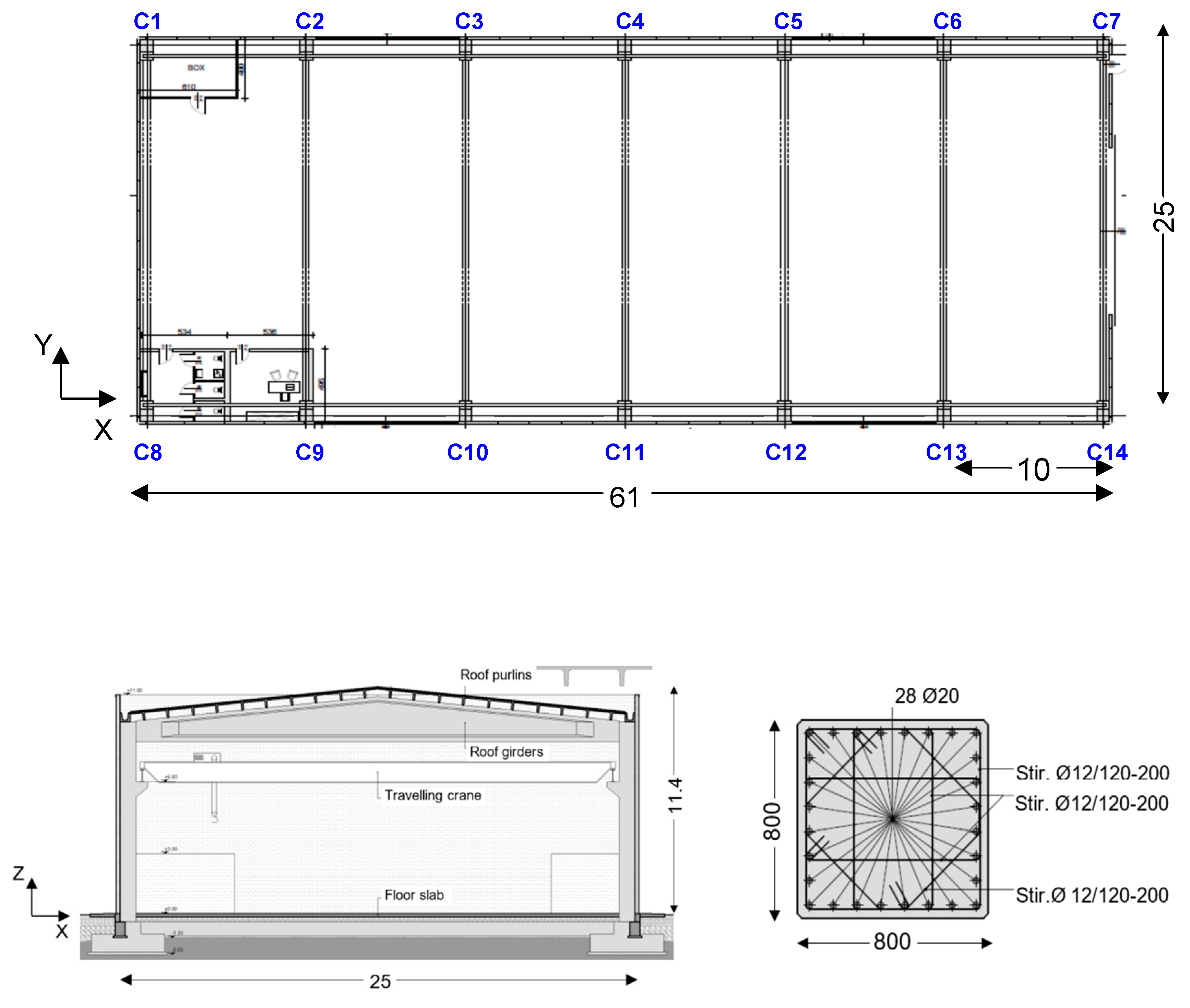
According to the prescriptions of Italian Standards [8], the traditional seismic design solution of the building was carried out by assuming a behavior factor q = 2.5, corresponding to ductility class “B” for this structural typology. The plan and a section of the building are illustrated in Figure 1. The structure is composed of 14 R/C prefab columns, with height of 10.6 m and cross section shown in the same figure, and seven pre-stressed R/C girders, with net span of 24.2 m. The roof is made of pre-stressed R/C purlins, over which a supplementary R/C slab is cast. The concrete and the steel used for the columns are class 45/55 and B450C, respectively. The foundation footings are linked to columns by a set of steel connectors guaranteeing a mutual monolithic joint, and have sides of 3700 mm, bottom flange height of 900 mm, and total height of 1500 mm. The cladding panels have pinned-type slotted connections to the columns. Further details on the structural system are reported in [7].
The finite analyses were carried out by taking into account the effect of cracking in the R/C members, assuming a reduced flexural stiffness equal to 70% of the stiffness of the uncracked element, for columns, and 50%, for longitudinal V beams. No reduction was considered for the pre-stressed roof girders.
The modal parameters evaluated by this assumption are as follows: the first mode is translational in X direction, with a vibration period of 1.377 s and effective modal mass (EMM) equal to 97.4% of the total seismic mass of the building; the second mode is translational in Y direction, with period of 1.364 s and EMM equal to 96.9%; and the third mode is rotational around the Z axis, with period of 1.307 s and EMM equal to 97.7%.
3. Dissipative Connection-Based Design Solutions
3.1. Earthquake Design Levels
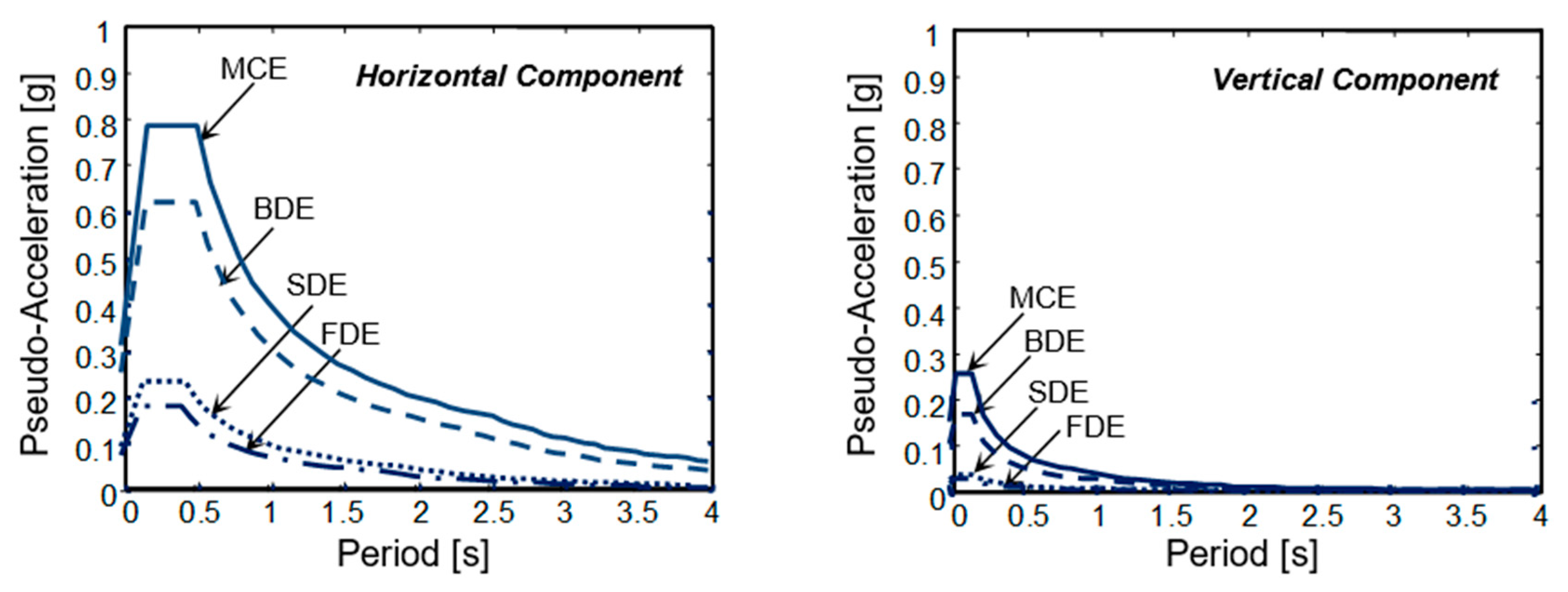
Like for the traditional anti-seismic solution recalled in the previous Section, the two advanced protection designs were carried out for the four reference seismic levels fixed in the Italian Standards [8], that is, frequent design earthquake (FDE), serviceability design earthquake (SDE), basic design earthquake (BDE) and maximum considered earthquake (MCE), having 81%, 63%, 10% and 5% probabilities of being exceeded over the reference time period, fixed at 50 years. The assumed topographic category is T1 (i.e., flat surface), and soil is C-type (medium-dense sand). Relevant elastic pseudo-acceleration response spectra are graphed in Figure 2. Time–history analyses were developed by assuming artificial ground motions as inputs, generated in families of seven from the spectra above, both for the horizontal components and the vertical one.
3.2. Roof Isolation System
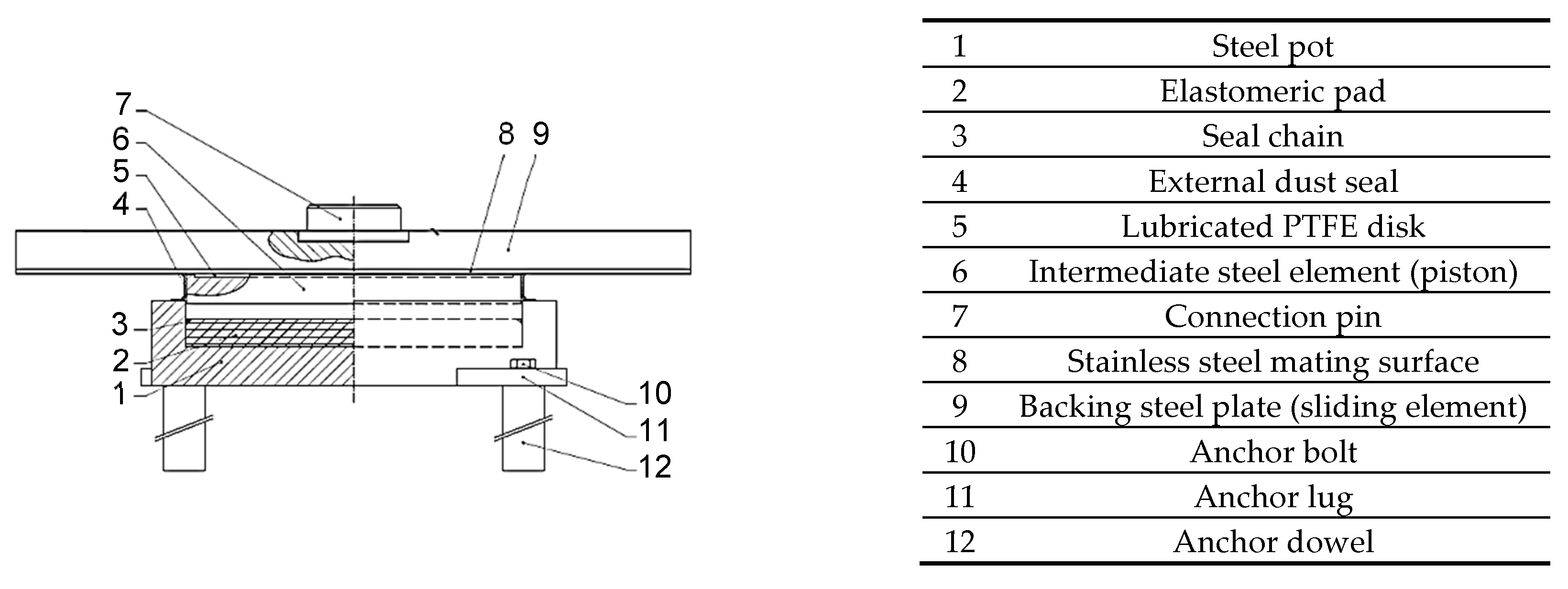
The roof isolation system is made of steel-PTFE multi-directional flat sliding bearings, of the same type as the ones usually installed in base isolation systems [9,10,11,12,13,14,15,16], placed on top of columns. The cross section and the constituting components of the devices are shown and listed in Figure 3.
All sliding bearings have the following dimensions, as drawn from the manufacturer’s catalogue [17]: internal diameter of the steel pot D0 = 200 mm; diameter of the backing steel plate Ds = 400 mm; total height H = 90 mm. The maximum allowable vertical load, Nall, and lateral displacements, dmax, are equal to Nall = 1250 N and dmax = ±100 mm, respectively. The friction coefficient in dynamic response conditions for a vertical load equal to Nall is equal to 0.01. In view of this low value, dissipaters must be incorporated in the girder-to-column joins to obtain a proper supplemental damping level of the seismic protection system.
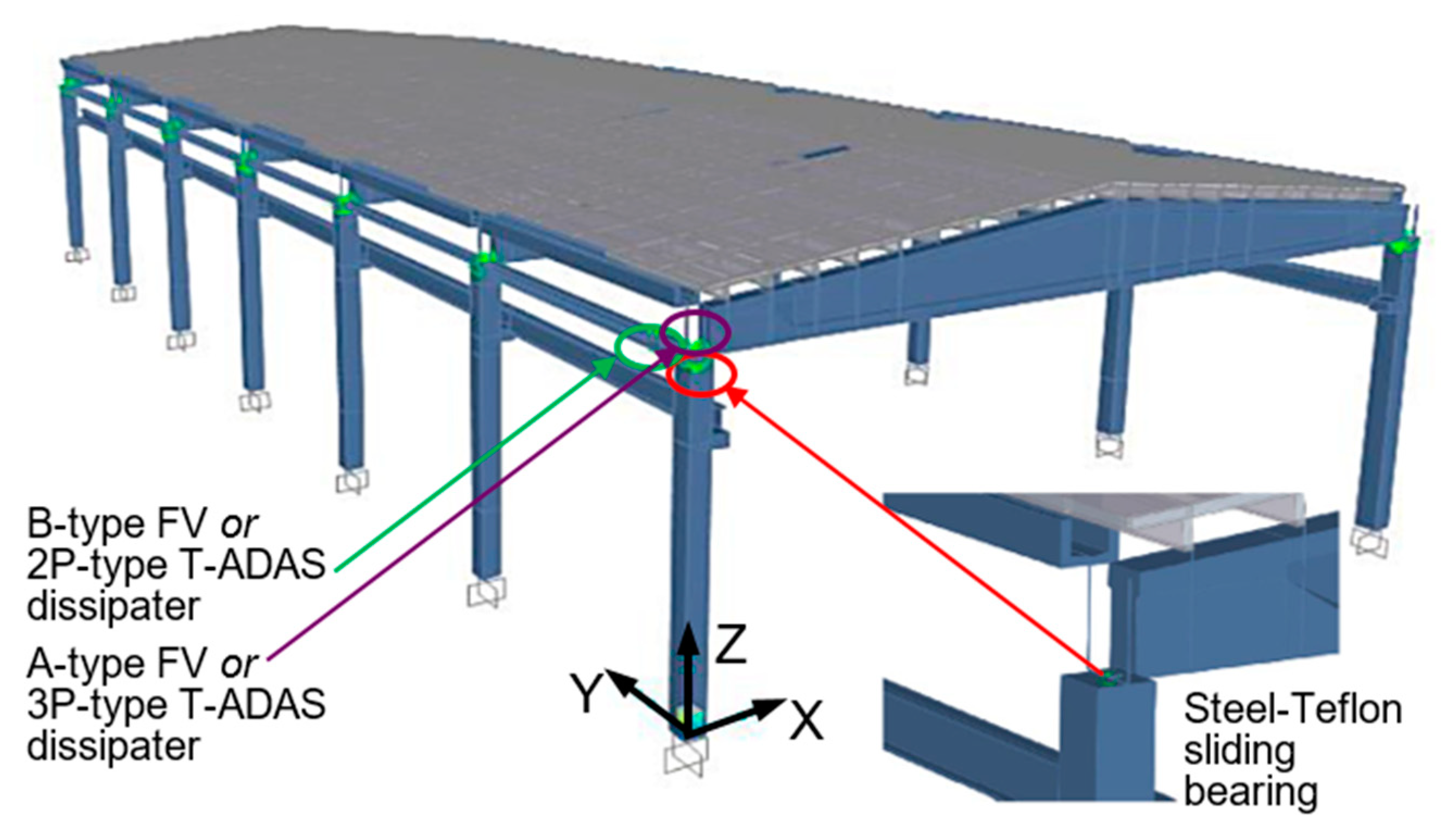
The finite element model of the structure, shown in Figure 4, was generated by SAP2000NL software [18]. In this image, the positions of the two types of dissipaters alternatively adopted as protective devices are also highlighted, in addition to the positions of the steel-PTFE sliders.
The response of the steel-PTFE bearings was modelled by a “friction isolator” element, characterized by a Coulomb-type hysteretic response law.
4. Discussion
4.1. Design Solution Incorporating FV Spring-Dampers
The FV devices considered as dissipative devices in this first design strategy, belonging to the general class of spring-dampers adopted in anti-seismic design [19,20,21,22,23,24], have been extensively studied by the authors for applications to new structures and infrastructures [25,26,27] and retrofit of existing ones [28,29,30,31,32].
As discussed in [25], the Fd damping and Fne non-linear elastic reaction forces corresponding to the damper and spring function of FV spring-dampers can be analytically expressed as follows:
where: t = time variable; c = damping coefficient; sgn(·) = signum function; (t) = velocity; |·| = absolute value; α = fractional exponent, ranging from 0.1 to 0.2; F0 = static pre-load; k1, k2 = stiffness of the response branches situated below and beyond F0; and s(t) = displacement. For the development of the numerical analyses, the FV spring-damper model is obtained by combining in parallel a non-linear dashpot and a non-linear spring with reaction forces given by expressions (1) and (2).
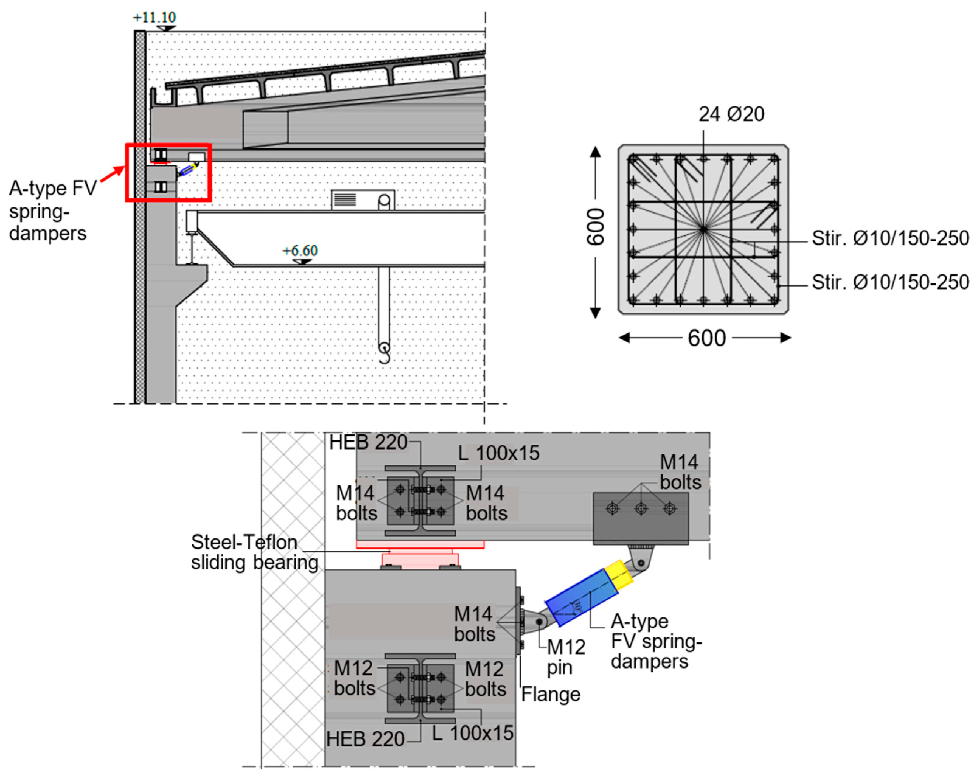
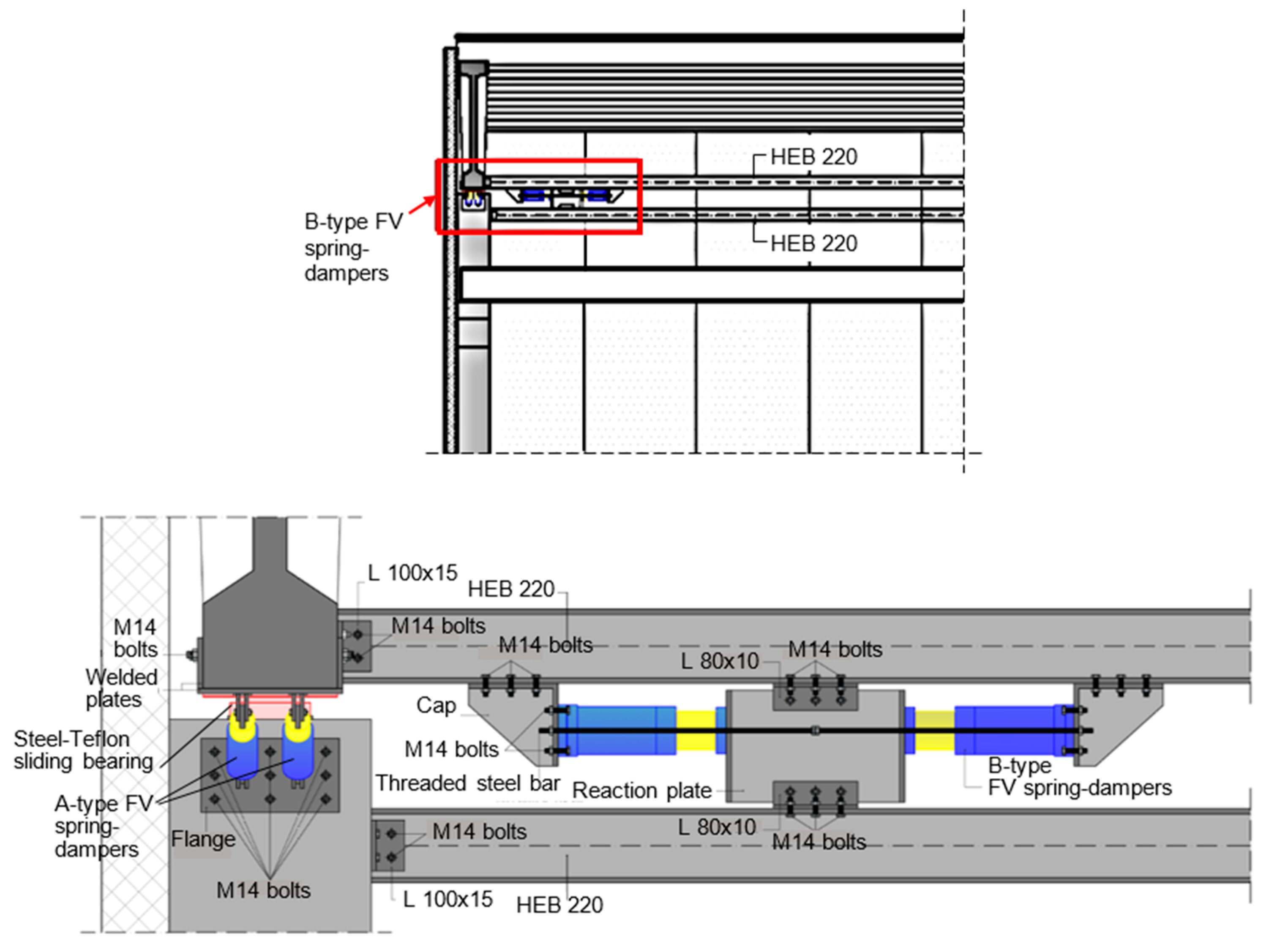
As illustrated by the drawings in Figure 5 and Figure 6, the dissipaters are always installed in pairs, and namely: with in-parallel diagonal layout at the 14 girder-to-column connections, in the X–Z vertical plan (A-type FV spring-dampers, 28 in total); with in-series horizontal layout at both ends of two HEB 220 steel beams linking the column top sections and the base “bulbs” of the girders, per each longitudinal side of the building, in the Y–Z vertical plan (B-type, eight in total).
The FV devices were designed by referring to the criterion proposed in [25], recently updated in [32], for any type of protective system incorporating them. The criterion consists in assigning the spring-dampers the capability of dissipating a prefixed energy fraction, Ed,t, of the seismic input energy, Ei,t. By targeting an elastic response of the structure up to the MCE, and by also considering the frictional contribution to the energy dissipation balance supplied by the steel-PTFE bearings, Ed,t was fixed at 75% of Ei,t calculated for the MCE. The resulting Ed,t demand is met by a set of 28 small-size A-type devices in current production [33], with energy dissipation capacity, Ec, equal to 7 kNm, and stroke, xmax, of 80 mm, and a set of eight medium-size B-type devices with En = 25 kNm and xmax = ±65 mm (obtained by starting from the half-stroke mounting position imposed on them, as commented below). Based on these choices, the total nominal energy dissipation capacities of the A-type and B-type sets of devices result to be very similar (196 kNm—A, against 200 kNm—B). The in-series mounting scheme of the B-type device pairs allows mutually pre-stressing them up to half-stroke, thus obtaining continuous (i.e., not origin-passing) response cycles, like for other supplemental damping systems where FV spring-dampers are installed horizontally [25,26,27,28,29,30,31,32].
The column sections deriving from the design analysis are shown in Figure 5. Footings have plan sizes of 2700 mm, bottom flange height of 600 mm, and total height of 1100 mm, giving rise to reductions of 45% and 14% in terms of total concrete volume and quantity of reinforcement, respectively, as compared to the traditional design.
The modal parameters for the structure equipped with the FV dissipative connections are as follows: the first mode is translational in Y, with period of 2.414 s and EMM equal to 95.7% of the total seismic mass; the second mode is translational in X, with period of 2.265 s and EMM equal to 93.7%; and the third mode is rotational around Z, with period of 2.164 s and EMM equal to 91.1%. The increase in period values, as compared to the conventionally designed structure, is primarily caused by the significant reduction of the cross sections of columns. A slightly greater increase is obtained in Y, because the total axial stiffness of the eight B-type FV spring-dampers, constituting the translational stiffness along this axis of the girder-to-column sliding connections in isolated-roof configuration, is lower than the horizontal component of the total axial stiffness of the 28 A-type FV spring-dampers along X. However, the contribution of the two sets of spring-dampers to the total translational stiffness of the structure is low, since the axial stiffness of their spring components is very small for both types of devices [25]. This motivates the remarkable elongation of the vibration periods obtained as compared to the traditional design.
The results of the final verification and performance evaluation analyses for this design solution are assessed in terms of response cycles of the FV dissipaters and steel-PTFE bearings, maximum base shear and energy balance.
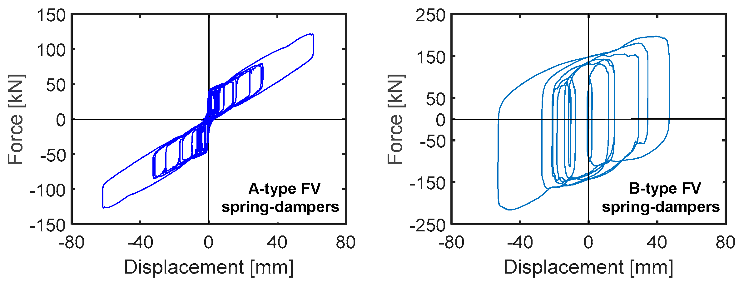
The response cycles displayed in Figure 7 exhibit peak displacements of the most stressed A-type and B-type devices equal to 63,7 mm and 55.7 mm, respectively, i.e., about 0.8 times (A-type) and 0.86 times (B-type) the available stroke limits mentioned above. In the graph referred to the A-type spring-damper pair, the response of the device on the right of the assembly is conventionally plotted with positive signs of force and displacement, while the device on the left has negative signs, which originates the “butterfly”-like path of the cycles.
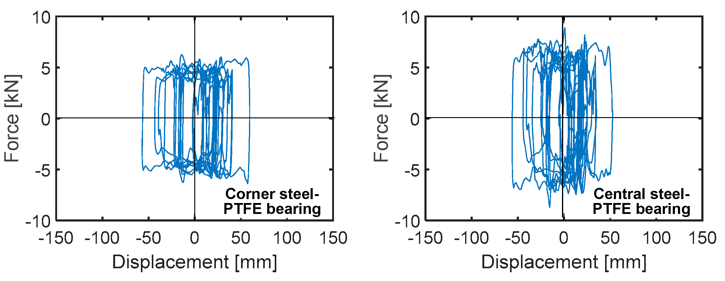
The response cycles in X direction of the most stressed steel-PTFE isolators situated on top of one corner column and one central column, graphed in Figure 8, highlight similar maximum displacements, equal to 58.9 mm and 53.2 mm, respectively. This underlines very low torsional response effects of the building in plan. Both peak values are far below the isolator displacement capacity of ±100 mm.
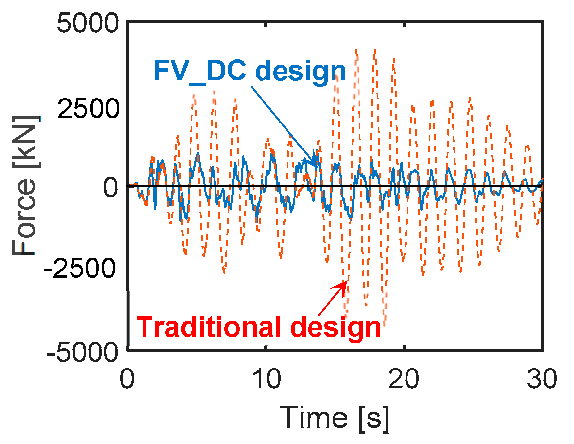
The base shear time-histories in X direction, along which a slightly higher response is computed as compared to Y (due to the slightly higher total translational stiffness obtained along X axis), plotted in Figure 9, show a reduction factor of about 4.1 for the FV dissipative connection-based design (denoted as FV_DC in the graph) in comparison to the conventional one. This determines an elastic response of columns up to the MCE, as targeted for this design.
The response in terms of displacements is assessed by means of the drift ratio (i.e., the ratio of drift to height) measured on top of columns, where the cladding panels have their upper pinned connections to the structure. The maximum drift ratio values are equal to 0.19% (FDE), 0.27% (SDE) and 0.64% (BDE), i.e., below the operational (OP) performance level-related limitation of 0.66% imposed in [8] for simply pinned prefab cladding panels. At the same time, the drift ratio reaches peak values of 0.79% at the MCE, i.e., restricted within the 1% limitation assumed by the same Standards for the immediate occupancy (IO) performance level. On the other hand, for the conventional design the peak drift ratios widely exceed this threshold, reaching 1.78% (BDE) and 2.13% (MCE), i.e., below the life safety (2%) and collapse prevention (2.5%) non-structural performance level-related limits, respectively.
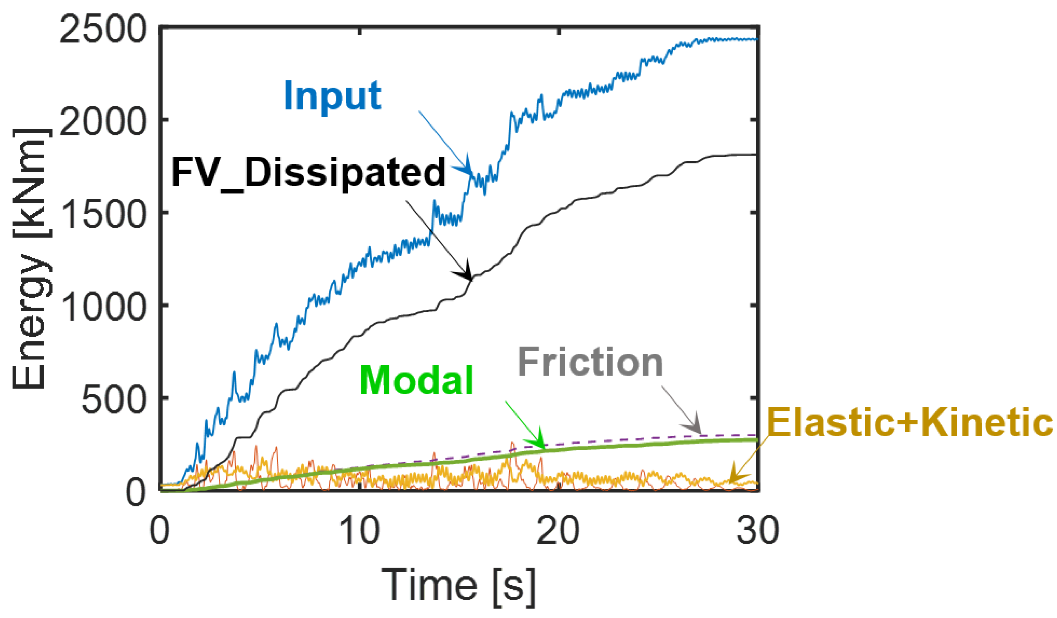
The energy time-histories plotted in Figure 10, computed in output by the SAP2000 software according to the classical Uang-Bertero energy equation [34] (where modal energy represents the term associated with the linear viscous damping matrix of the structural system), demonstrate that the energy dissipated by the FV devices, equal to 74.3% of the input energy, nearly coincides with the targeted 75%.
The remaining portion is shared practically equally between the friction energy produced by the response of the steel-PTFE isolators and the modal energy.
The estimated total cost of the structure amounts to about €643,000, corresponding to a cost per square meter of 421 €/m2, that is, 5.4% greater than the cost of the conventional design (€610,000, equivalent to 400 €/m2).
4.2. Design Solution Incorporating T-ADAS Dampers
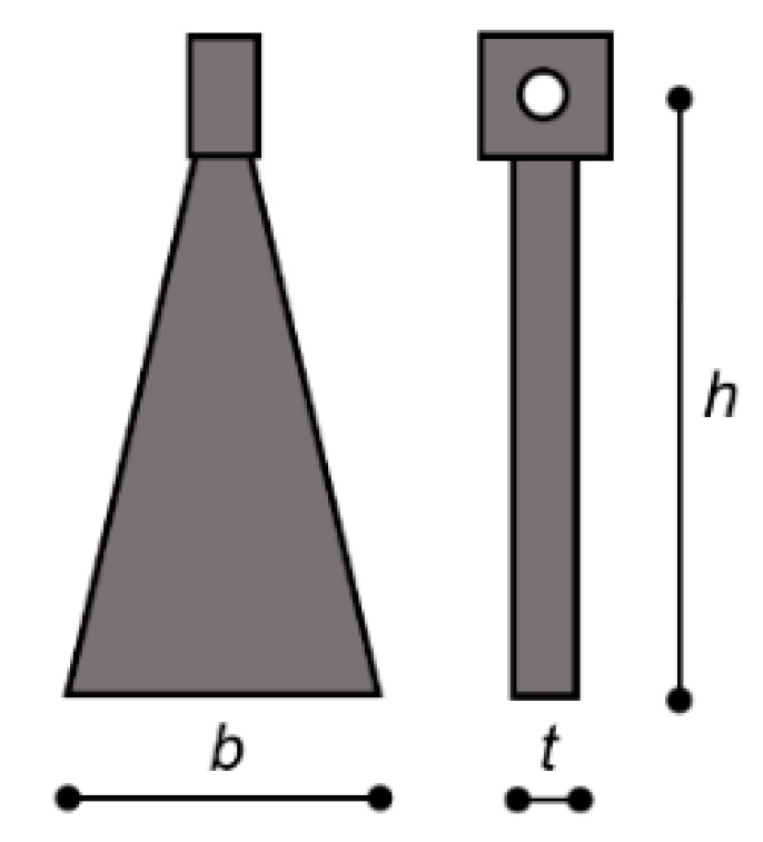
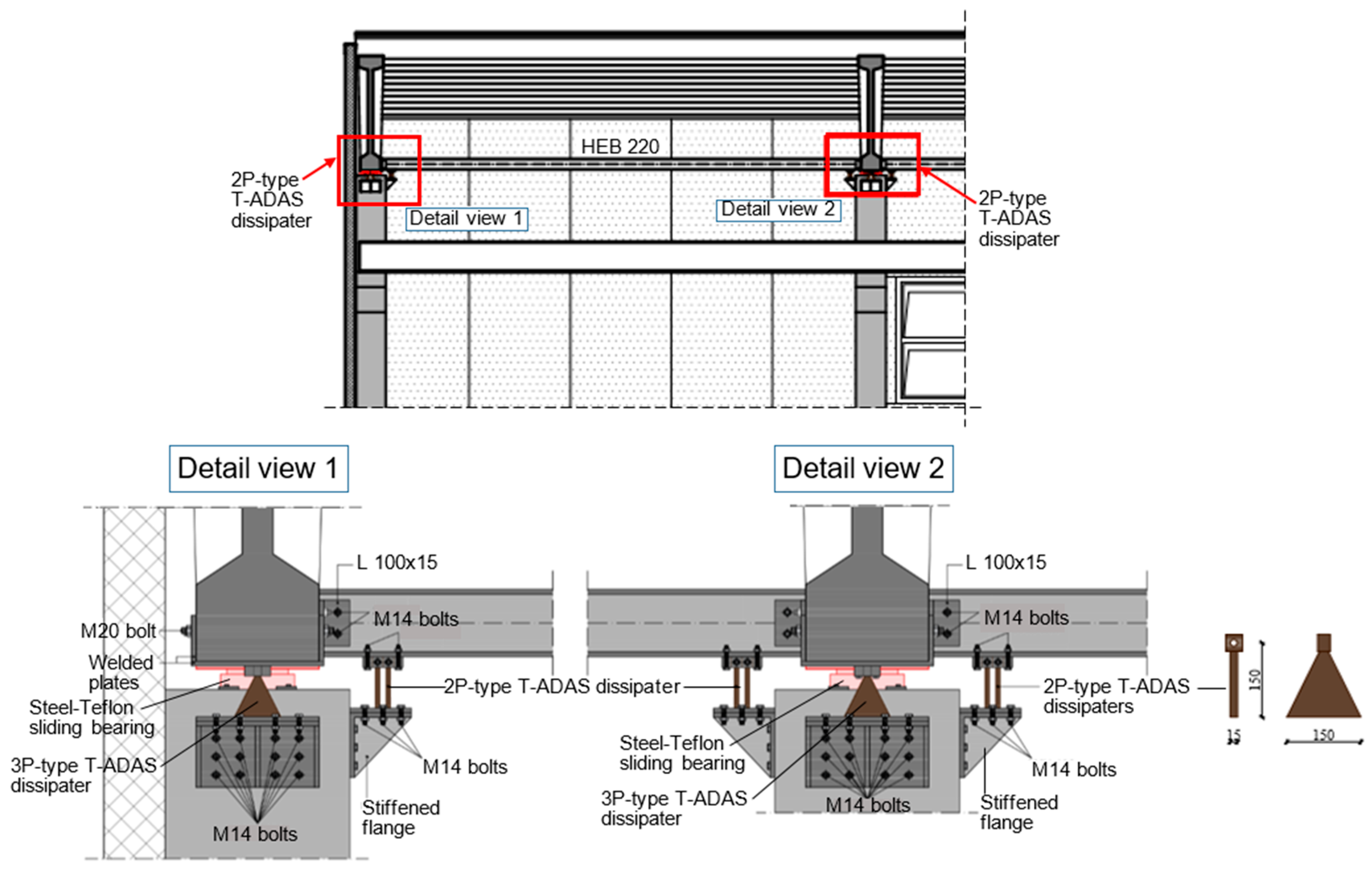
T-ADAS dampers consist in the assembly of isosceles triangle-shaped steel plates vertically mounted on top of the supporting diagonal braces [35,36,37,38,39]. According to the symbols in Figure 11, the following typical dimensions of the plates were adopted [29,36,37]: h = 150 mm, t = 15 mm, and b = 150 mm. The constituting steel is S 450 type, with yielding stress, fy, of 450 MPa, and ultimate stress, ft, of 690 MPa.
In order to fix the number of plates per device, Np, the sizing criterion adopted for FV spring-dampers, i.e., assigning the dissipative connections a damping energy capacity Ed,t equal to 75% of the input energy Ei,t calculated for the MCE, was extended to T-ADAS devices too. Since a preliminary estimate of Ei,t at the MCE-scaled input action provided a rounded value of 2000 kNm, Ed,t was correspondingly fixed at about 1500 kNm, to be shared among all dissipaters. Based on the expression of the yielding force, Py, of a plate
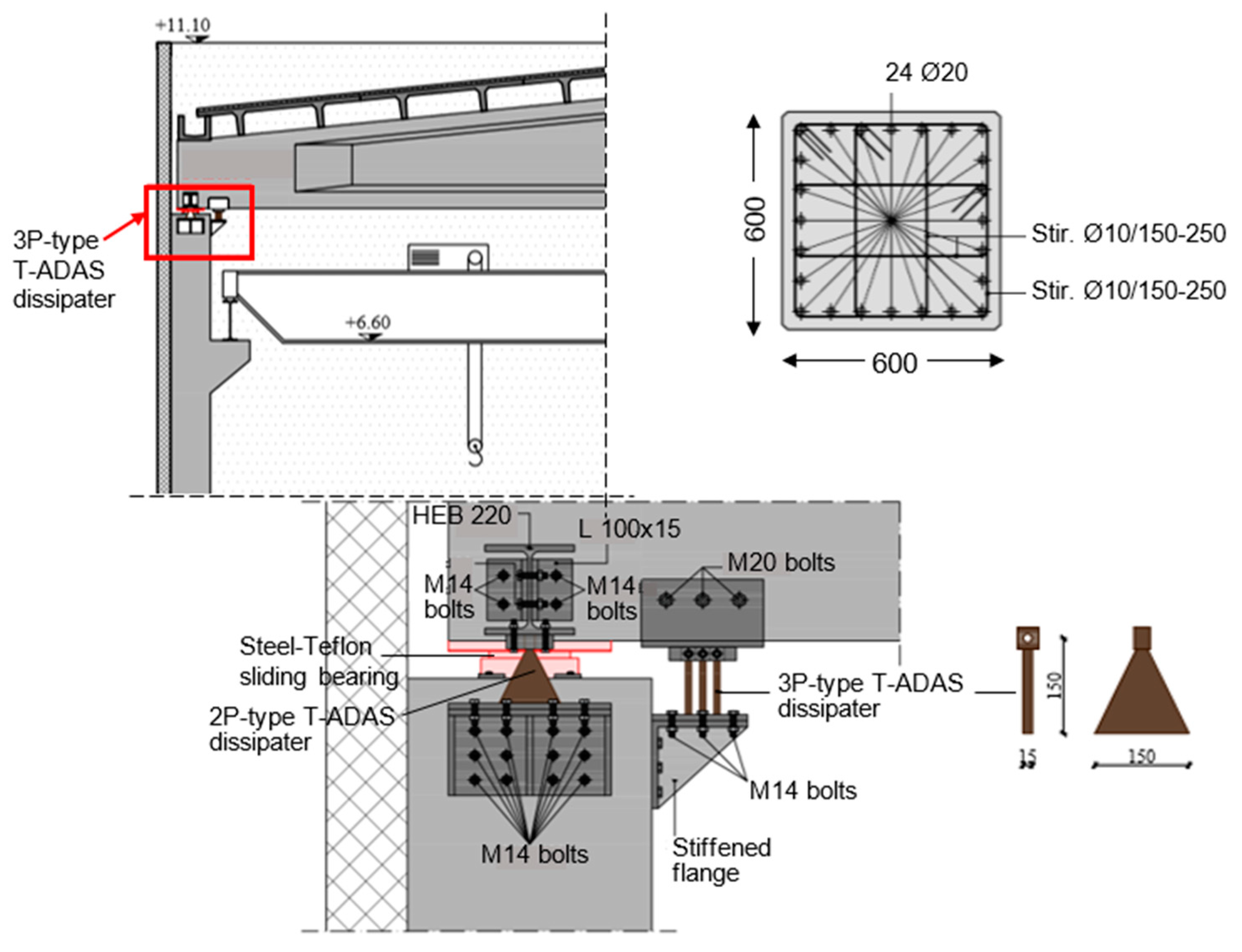
Which gives a Py value of 16.9 kN, and by assuming maximum positive and negative displacements of the dampers approximately equal to the values obtained for the FV devices, tentatively rounded here to ±60 mm, the energy dissipated by a single plate in the maximum response cycle, Ep,s, is equal to about 4.1 kNm. By observing that the energy dissipated in all the remaining cycles is approximately equal to 4 Ep,s [39], the total energy dissipated by a plate, Ep,t, is tentatively fixed at Ep,t = 4 Ep,s = 16.4 kNm. The sizing value of Np, Np,s, is thus obtained by dividing Ed,t = 1500 kNm by Ep,t = 16.4 kNm, obtaining a ratio of about 91, rounded to Np,s = 90. This value is split in the two directions in plan by assuming 3 plates for the 14 dissipaters in X (named 3P-type in the following), for a total of 42 plates, and 2 plates for the devices in Y (2P-type), situated at each girder-to-column joint (one dissipater in the corner joints and two in the central joints), for a total of 24 devices and 48 plates.
Detailed drawings concerning the installation of the T-ADAS dampers are shown in Figure 12 and Figure 13. The column sections resulting from the design analysis, displayed in Figure 12, as well as the foundation footings, are the same as for the FV dissipative connection solution.
The modal parameters for the T-ADAS dampers-equipped structure are as follows: the first mode is translational in X, with period of 2.233 s and EMM equal to 96.4% of the total seismic mass; the second mode is translational in Y, with period of 2.186 s and EMM equal to 95.3%; and the third mode is rotational around Z, with period of 2.071 s and EMM equal to 92.7%. In this case, a slightly greater increase is obtained in X, as a consequence of the slightly lower total translational stiffness of the 42 plates installed along it, as compared to the 48 plates along Y.
Like for the FV dissipative connection-based design, the results of the final verification analyses are assessed in terms of response cycles of the dissipaters and the steel-PTFE bearings, maximum base shear and energy balance.
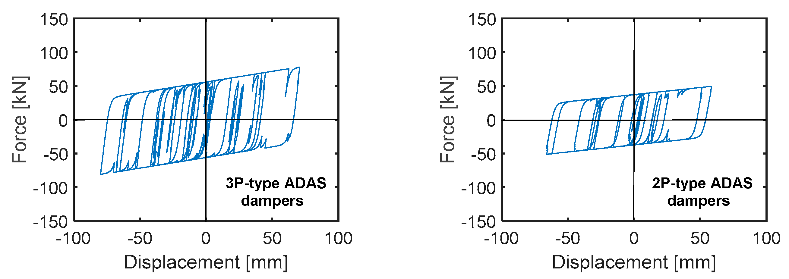
The response cycles in Figure 14 highlight peak displacements of 78.2 mm and 67.7 mm for 3P-type and 2P-type dissipaters, respectively. Both values are below the mutual value of the nominal ultimate displacement, i.e., the value corresponding to the attainment of the nominal ultimate force of the plates, equal to 96 mm.
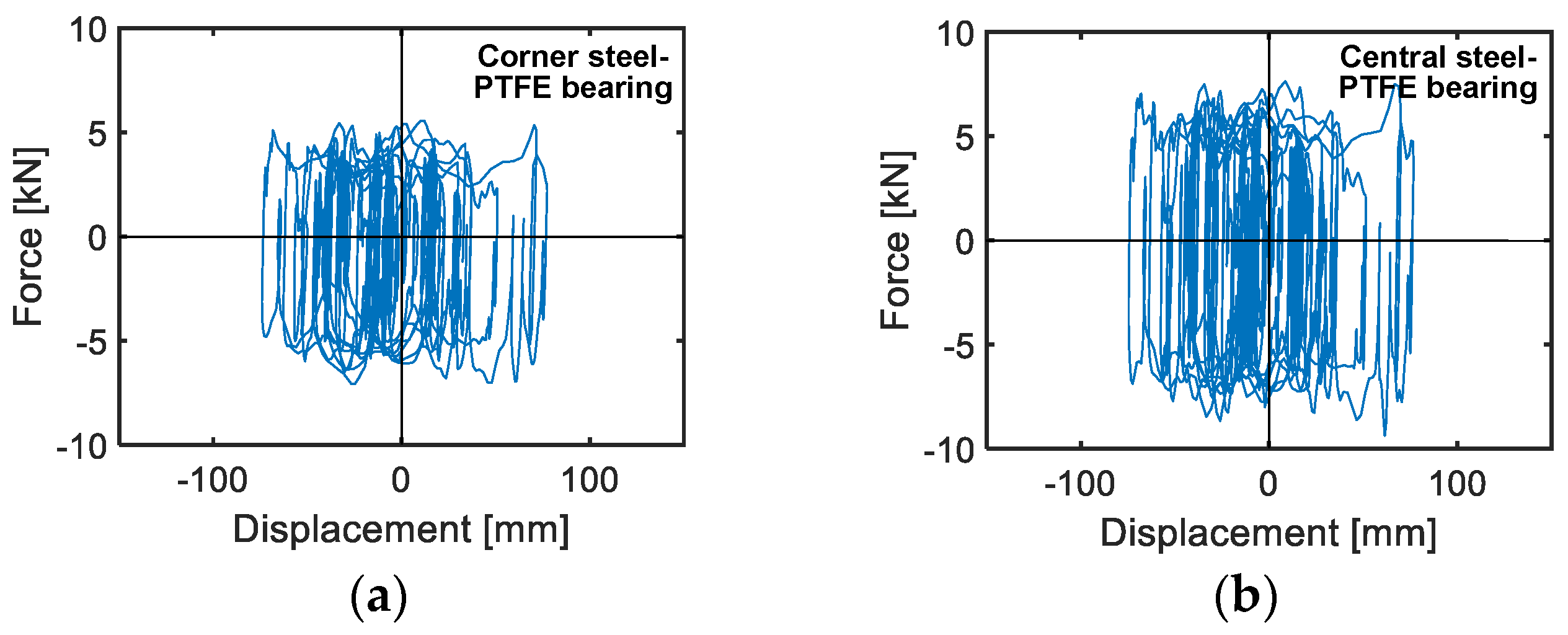
The response cycles in X direction of the same steel-PTFE isolators which Figure 8 is referred to, illustrated in Figure 15, highlight similar maximum displacements of a corner and a central bearing (equal to 82.1 mm and 81.3 mm) in this case too. This confirms the very low torsional response effects of the building in plan already observed for the FV connection-based solution. Both peak values are about 35% greater than the corresponding values obtained for the latter, as a consequence of the proportionally higher displacements of the T-ADAS dampers as compared to the FV devices, but still distant from the isolator displacement limit of ±100 mm.
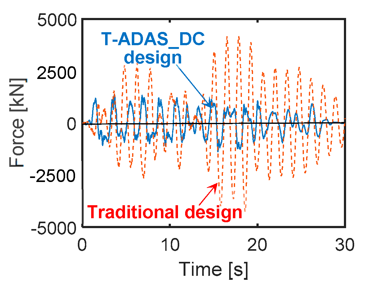
The base shear time-histories in X direction, plotted in Figure 16, identify a slightly lower reduction factor when passing from the traditional to the T-ADAS dissipative connection-based design (denoted as T-ADAS_DC), as compared to the FV-based one, i.e., equal to 3.55 instead of 4.1. This is due to the slightly higher stiffness of the steel dampers and, consequently, of the structural system. Nonetheless, a completely elastic response of all structural members up to the MCE is obtained in this case too.
The maximum drift ratios measured in correspondence with the column tops are nearly coinciding with the values observed for the FV dissipative connection-based solution, i.e., equal to 0.21%, 0.28%, 0.65% and 0.8% at the FDE, SDE, BDE and MCE, respectively. Therefore, in this case too, the drift ratios are below the OP-related limitation of 0.66% (FDE, SDE, BCE) and IO-related limitation of 1% (MCE) discussed above, guaranteeing a totally undamaged response of the cladding panels at the first three levels, and a very small damage in the pinned connections at the MCE.
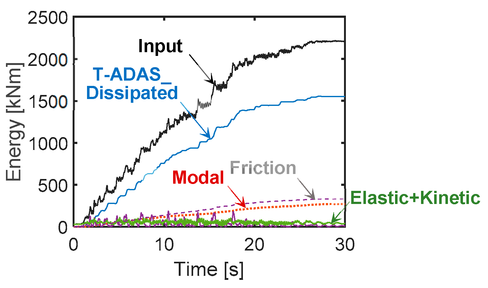
The energy time-histories graphed in Figure 17 highlight a contribution of 72.3% to the energy balance by the T-ADAS dampers, close to the targeted 75% for this design solution too. At the same time, the remaining dissipated energy is split in very similar portions between the frictional response of the steel-PTFE isolators and the modal energy, like for the FV dissipative connection-based design hypothesis.
The total cost of the structure amounts to about 654,000 Euros, corresponding to a cost per square meter of 429 Euros/m2, that is, 7.2% greater than the above-mentioned cost of the conventional design and 1.8% of the solution based on the incorporation of the FV spring-dampers.
5. Conclusions
The concept of roof isolation can be easily implemented in precast reinforced concrete structures, where roof girders are simply supported on column tops. Nonetheless, this strategy has been only sporadically applied to this class of buildings.
The study presented herein is aimed at providing new contributions to the topic, by proposing a seismic protection system where roof isolation is coupled to girder-to-column dissipative connections, incorporating either fluid viscous spring-dampers or T-ADAS steel devices.
The following remarks are conclusively drawn from the study carried out, referred to a medium seismicity site representative of several other zones of the Italian territory characterized by comparable PGA values for the four seismic levels assumed in the national Technical Standards.
- −
- Notably smaller sizes of columns and footings are obtained for the two advanced design solutions, with reductions of the concrete volume and reinforcement of 45% and 14%, respectively, as compared to the conventional design.
- −
- A completely elastic structural response is guaranteed by the two dissipative systems up to the MCE level.
- −
- For both systems, the maximum drift ratio values measured on top of columns are below the OP performance level-related 0.66% limitation, up to the BDE. At the same time, the peak values result to be within the 1% limitation relevant to the IO performance level, for the MCE.
- −
- On the other hand, remarkable structural damage is expected in the traditionally designed building beginning from the BDE, consistently with the assumption of a behaviour factor of 2.5.
- −
- The structural performance improvement obtained with the dissipative design solutions is also synthesized in terms of global response parameters, as highlighted by reduction factors of about 4.1 on base shear for the FV dissipative connection-based design, and 3.55 for the T-ADAS-based one, as compared to the conventional design.
- −
- Drift ratios for the traditional design are far above the immediate occupancy-related limitation, reaching 1.78% (BDE) and 2.13% (MCE). These values entail significant damage of the cladding panels connections, and thus the need to repair or replace them, beginning from seismic events with comparable amplitude to the BDE one.
- −
- For both types of dissipative connections, the energy dissipated by the dampers at the MCE is close to the 75% share of the input energy targeted in their designs. The remaining dissipated energy is split in nearly equal portions between the energy produced by the frictional response of the steel-PTFE isolators and the modal energy.
- −
- In view of the observations above, the two types of dissipative connections guarantee similar high seismic protection capacities.
- −
- The only difference in performance offered by the two systems consists in the completely undamaged response of the FV spring-dampers, as opposed to the damaged response of the T-ADAS steel yielding dissipaters caused by the development of repeated plastic deformation cycles, beginning from the BDE seismic level.
- −
- The cost of the two advanced designs is 5.4% (FV spring-dampers) and 7.2% (T-ADAS dissipaters) greater than the cost of the conventional design.
- −
- However, a complete economic comparison between the different designs must take into account the cost of the remarkable repair interventions required for the traditional building, as well as the cost related to its interruption of usage in post-quake conditions and during the execution of relevant works.
Author Contributions
Conceptualization, S.S. and G.T.; methodology, S.S. and G.T.; software, S.S. and G.T.; validation, S.S.; formal analysis, S.S. and G.T.; investigation, S.S. and G.T.; resources, S.S. and G.T.; data curation, G.T.; writing—original draft preparation, S.S. and G.T.; writing—review and editing, S.S. and G.T.; funding acquisition, S.S. and G.T. All authors have read and agreed to the published version of the manuscript.
Funding
ReLUIS-DPC Project 2019–2021 (Work Package 15: Normative Contributions for Isolation and Dissipation).
Conflicts of Interest
The authors declare no conflict of interest.
References
- Negro, P.; Toniolo, G. Design Guidelines for Connections of Precast Structures under Seismic Actions; Report JRC71599—EUR 25377 EN; Publication Offices of the European Union: Luxembourg, 2012. [Google Scholar]
- Fischinger, M.; Zoubek, B.; Isaković, T. Seismic Response of Precast Industrial Buildings. In Perspectives on European Earthquake Engineering and Seismology; Ansal, A., Ed.; Geotechnical, Geological and Earthquake Engineering; Springer: Cham, Switzerland, 2014; Volume 34. [Google Scholar] [CrossRef] [Green Version]
- Sezen, H.; Whittaker, A.S. Seismic Performance of Industrial Facilities Affected by the 1999 Turkey Earthquake. J. Perform. Constr. Facil. 2006, 20, 28–36. [Google Scholar] [CrossRef]
- Toniolo, G.; Colombo, A. Precast concrete structures: The lessons learned from the L’Aquila earthquake. Struct. Concr. 2012, 13, 73–83. [Google Scholar] [CrossRef]
- Sorace, S.; Terenzi, G. Existing prefab R/C industrial buildings: Seismic assessment and supplemental damping-based retrofit. Soil Dyn. Earthq. Eng. 2017, 94, 193–203. [Google Scholar] [CrossRef] [Green Version]
- Soydan, C.; Yuksel, E.; Irtem, E. Seismic performance improvement of single-storey precast reinforced concrete industrial buildings in use. Soil Dyn. Earthq. Eng. 2020, 135, 106167. [Google Scholar] [CrossRef]
- Sorace, S.; Terenzi, G. Innovative Structural Solutions for Prefab Reinforced Concrete Hall-Type Buildings. Open Constr. Build. Technol. J. 2019, 13, 149–163. [Google Scholar] [CrossRef] [Green Version]
- Ministry of Infrastructure and Transport. Update of Technical Standards for Constructions; Ministry of Infrastructure and Transport: Rome, Italy, 2018. (In Italian)
- Fenz, D.M.; Constantinou, M.C. Behaviour of the double concave Friction Pendulum bearing. Earthq. Eng. Struct. Dyn. 2006, 35, 1403–1424. [Google Scholar] [CrossRef]
- Sorace, S.; Terenzi, G. A viable base isolation strategy for the advanced seismic retrofit of an R/C building. Contemp. Eng. Sci. 2014, 7, 817–834. [Google Scholar] [CrossRef]
- Sorace, S.; Terenzi, G. Analysis, Design, and Construction of a Base-Isolated Multiple Building Structure. Adv. Civ. Eng. 2014, 2014, 1–13. [Google Scholar] [CrossRef] [Green Version]
- Ponzo, F.C.; Di Cesare, A.; Leccese, G.; Nigro, D. Shaking table tests of a base isolated structure with Double Concave Friction Pendulum bearings. Bull. N. Z. Soc. Earthq. Eng. 2015, 48, 136–144. [Google Scholar] [CrossRef]
- Foti, D. Response of frames seismically protected with passive systems in near-field areas. Int. J. Struct. Eng. 2014, 5, 326. [Google Scholar] [CrossRef]
- Mazza, F.; Mazza, M. Nonlinear seismic analysis of irregular r.c. framed buildings base-isolated with friction pendulum system under near-fault excitations. Soil Dyn. Earthq. Eng. 2016, 90, 299–312. [Google Scholar] [CrossRef]
- Mazza, F.; Mazza, M. Sensitivity to modelling and design of curved surface sliding bearings in the nonlinear seismic analysis of base-isolated r.c. framed buildings. Soil Dyn. Earthq. Eng. 2017, 100, 144–158. [Google Scholar] [CrossRef]
- Quaglini, V.; Gandelli, E.; Dubini, P. Experimental investigation of the re-centring capability of curved surface sliders. Struct. Control. Heal. Monit. 2017, 24, e1870. [Google Scholar] [CrossRef]
- FIP. Anti-Seismic Devices Product Division. 2019. Available online: http://www.fip-group.it (accessed on 30 September 2020).
- SAP2000NL. Theoretical and Users’ Manual. Release 21.06; Computers & Structures Inc.: Berkeley, CA, USA, 2020. [Google Scholar]
- Constantinou, M.C.; Soong, T.T.; Dargush, G.F. Passive Energy Dissipation Systems for Structural Design and Retrofit; Monograph Series, No. 1; MCEER: New York, NY, USA, 1998; ISBN 0-9656682-1-5. [Google Scholar]
- Lago, A.; Trabucco, D.; Wood, A. Damping Technologies for Tall Buildings. Theory, Design Guidance and Case Studies; Elsevier: Butterworth, South Africa, 2018; ISBN 9780128159637. [Google Scholar]
- Lu, Z.; Wang, Z.; Zhou, Y.; Lu, X. Nonlinear dissipative devices in structural vibration control: A review. J. Sound Vib. 2018, 423, 18–49. [Google Scholar] [CrossRef]
- De Domenico, D.; Ricciardi, G.; Takewaki, I. Design strategies of viscous dampers for seismic protection of building structures: A review. Soil Dyn. Earthq. Eng. 2019, 118, 144–165. [Google Scholar] [CrossRef]
- Wang, W.; Fang, C.; Zhang, A.; Liu, X. Manufacturing and performance of a novel self-centring damper with shape memory alloy ring springs for seismic resilience. Struct. Control. Heal. Monit. 2019, 26, e2337. [Google Scholar] [CrossRef]
- Katsimpini, P.S.; Papagiannopoulos, G.A.; Askouni, P.K.; Karabalis, D.L. Seismic response of low-rise 3-D steel structures equipped with the seesaw system. Soil Dyn. Earthq. Eng. 2020, 128, 105877. [Google Scholar] [CrossRef]
- Sorace, S.; Terenzi, G. Seismic Protection of Frame Structures by Fluid Viscous Damped Braces. J. Struct. Eng. 2008, 134, 45–55. [Google Scholar] [CrossRef]
- Sorace, S.; Terenzi, G.; Fadi, F. Shaking Table and Numerical Seismic Performance Evaluation of a Fluid Viscous-Dissipative Bracing System. Earthq. Spectra 2012, 28, 1619–1642. [Google Scholar] [CrossRef] [Green Version]
- Sorace, S.; Terenzi, G.; Bertino, G. Viscous dissipative, ductility-based and elastic bracing design solutions for an indoor sports steel building. Adv. Steel Constr. 2012, 8, 295–316. [Google Scholar] [CrossRef] [Green Version]
- Sorace, S. Dissipative Bracing-Based Seismic Retrofit of R/C School Buildings. Open Constr. Build. Technol. J. 2012, 6, 334–345. [Google Scholar] [CrossRef] [Green Version]
- Sorace, S.; Terenzi, G.; Mori, C. Passive energy dissipation-based retrofit strategies for R/C frame water towers. Eng. Struct. 2016, 106, 385–398. [Google Scholar] [CrossRef]
- Sorace, S.; Terenzi, G.; Licari, M. Traditional and viscous dissipative steel braced top addition strategies for a R/C building. Int. J. Struct. Eng. 2015, 6, 332. [Google Scholar] [CrossRef]
- Terenzi, G.; Costoli, I.; Sorace, S. Activation control extension of a design method of fluid viscous dissipative bracing systems. Bull. Earthq. Eng. 2020, 18, 4017–4038. [Google Scholar] [CrossRef]
- Terenzi, G. Energy-Based Design Criterion of Dissipative Bracing Systems for the Seismic Retrofit of Frame Structures. Appl. Sci. 2018, 8, 268. [Google Scholar] [CrossRef] [Green Version]
- Jarret, S.L. Shock-Control Technologies. 2019. Available online: http://www.introini.info (accessed on 12 October 2020).
- Uang, C.M.; Bertero, V.V. Use of Energy as a Design Criterion in Earthquake-Resistant Engineering; Report UCB-EERC 88/18; University of California at Berkeley: Berkely, CA, USA, 1988. [Google Scholar]
- Kelly, J.M.; Skinner, R.; Heine, A. Mechanisms of energy absorption in special devices for use in earthquake resistant structures. Bull. NZ Soc. Earthq. Eng. 1972, 5, 63–88. [Google Scholar]
- Xia, C.; Hanson, R.D. Influence of ADAS Element Parameters on Building Seismic Response. J. Struct. Eng. 1992, 118, 1903–1918. [Google Scholar] [CrossRef]
- Tsai, K.-C.; Chen, H.-W.; Hong, C.-P.; Su, Y.-F. Design of Steel Triangular Plate Energy Absorbers for Seismic-Resistant Construction. Earthq. Spectra 1993, 9, 505–528. [Google Scholar] [CrossRef]
- Foti, D.; Diaferio, M.; Nobile, R. Optimal design of a new seismic passive protection device made in aluminium and steel. Struct. Eng. Mech. 2010, 35, 119–122. [Google Scholar] [CrossRef]
- Cancellara, D.; De Angelis, F. Steel Braces in Series with Hysteretic Dampers for Reducing the Seismic Vulnerability of RC Existing Buildings: Assessment and Retrofitting with a Nonlinear Model. Appl. Mech. Mater. 2012, 204–208, 2677–2689. [Google Scholar] [CrossRef]
Figure 1.
Plan and transversal section of the building (adapted from [7]—dimensions in meters), and cross section of columns obtained for the traditional design solution (dimensions in millimeters).
Figure 1.
Plan and transversal section of the building (adapted from [7]—dimensions in meters), and cross section of columns obtained for the traditional design solution (dimensions in millimeters).

Figure 2.
Normative pseudo-acceleration elastic response spectra.

Figure 3.
Cross section of a steel-PTFE multidirectional flat sliding bearing.

Figure 4.
Overall view of the finite element model of the structure.

Figure 5.
Installation details of A-type FV spring-dampers.

Figure 6.
Installation details of B-type FV spring-dampers.

Figure 7.
Response cycles of the most stressed A-type and B-type FV spring-damper pairs obtained from the most demanding MCE-scaled group of input accelerograms.
Figure 7.
Response cycles of the most stressed A-type and B-type FV spring-damper pairs obtained from the most demanding MCE-scaled group of input accelerograms.

Figure 8.
Response cycles in X direction of the most stressed corner and central steel-PTFE bearing obtained from the most demanding MCE-scaled group of input accelerograms.
Figure 8.
Response cycles in X direction of the most stressed corner and central steel-PTFE bearing obtained from the most demanding MCE-scaled group of input accelerograms.

Figure 9.
Base shear time-histories in X direction obtained from the most demanding MCE-scaled group of input accelerograms.
Figure 9.
Base shear time-histories in X direction obtained from the most demanding MCE-scaled group of input accelerograms.

Figure 10.
Energy time-histories of the structure obtained from the most demanding MCE-scaled group of input accelerograms.
Figure 10.
Energy time-histories of the structure obtained from the most demanding MCE-scaled group of input accelerograms.

Figure 11.
Geometrical parameters of the steel plates constituting the T-ADAS dampers.

Figure 12.
Installation details of 3P-type T-ADAS dissipaters.

Figure 13.
Installation details of 2P-type T-ADAS dissipaters.

Figure 14.
Response cycles of the most stressed 3P-type and 2P-type T-ADAS dissipaters obtained from the most demanding MCE-scaled group of input accelerograms.
Figure 14.
Response cycles of the most stressed 3P-type and 2P-type T-ADAS dissipaters obtained from the most demanding MCE-scaled group of input accelerograms.

Figure 15.
Response cycles in X direction of the most stressed corner and central steel-PTFE bearing obtained from the most demanding MCE-scaled group of input accelerograms.
Figure 15.
Response cycles in X direction of the most stressed corner and central steel-PTFE bearing obtained from the most demanding MCE-scaled group of input accelerograms.

Figure 16.
Base shear time-histories in X direction obtained from the most demanding MCE-scaled group of input accelerograms.
Figure 16.
Base shear time-histories in X direction obtained from the most demanding MCE-scaled group of input accelerograms.

Figure 17.
Energy time-histories of the structure obtained from the most demanding MCE-scaled group of input accelerograms.
Figure 17.
Energy time-histories of the structure obtained from the most demanding MCE-scaled group of input accelerograms.

Publisher’s Note: MDPI stays neutral with regard to jurisdictional claims in published maps and institutional affiliations. |
© 2020 by the authors. Licensee MDPI, Basel, Switzerland. This article is an open access article distributed under the terms and conditions of the Creative Commons Attribution (CC BY) license (http://creativecommons.org/licenses/by/4.0/).
Share and Cite
MDPI and ACS Style
Sorace, S.; Terenzi, G. Roof Isolation and Girder-to-Column Dissipative Connections in Seismic Design of Precast R/C Structures. Infrastructures 2020, 5, 104. https://0-doi-org.brum.beds.ac.uk/10.3390/infrastructures5110104
AMA Style
Sorace S, Terenzi G. Roof Isolation and Girder-to-Column Dissipative Connections in Seismic Design of Precast R/C Structures. Infrastructures. 2020; 5(11):104. https://0-doi-org.brum.beds.ac.uk/10.3390/infrastructures5110104
Chicago/Turabian StyleSorace, Stefano, and Gloria Terenzi. 2020. "Roof Isolation and Girder-to-Column Dissipative Connections in Seismic Design of Precast R/C Structures" Infrastructures 5, no. 11: 104. https://0-doi-org.brum.beds.ac.uk/10.3390/infrastructures5110104