Progressive Failure Analysis of a Concrete Dam Anchored with Passive Rock Bolts


Division of Concrete Structures, Department of Civil and Architectural Engineering, KTH the Royal Institute of Technology, 100 44 Stockholm, Sweden
*
Author to whom correspondence should be addressed.
Infrastructures 2020, 5(3), 28; https://0-doi-org.brum.beds.ac.uk/10.3390/infrastructures5030028
Submission received: 30 January 2020
/
Revised: 6 March 2020
/
Accepted: 7 March 2020
/
Published: 10 March 2020
(This article belongs to the Special Issue Advances in Dam Engineering)
Abstract
:Passive rock bolts are commonly used to anchor concrete dams, and they may have a significant impact on stability-evaluations. However, these bolts are often omitted from dam safety analysis due to uncertainties regarding their condition and the size of displacements required in the dam-rock interface to mobilize significant bearing forces in the passive rock bolts. This paper address the latter question by studying the failure process of a small concrete dam anchored with rock bolts. Failure simulations were performed with the increased density method in a finite element model consisting of a dam, the corresponding part of the rock and rock bolts. Two types of approaches are used to simulate the anchorage of the rock bolts; a method where the anchorage to the rock is simulated using a fixed boundary condition; and a method where the anchoring of the bolts are modelled using springs. Depending on the method of analysis, the rock bolts contribute with 40–75% of the load-carrying capacity of the dam. The rock bolts increase the load-bearing capacity of the dam, partly through anchorage forces, but also by keeping the contact surface between rock and concrete together and thereby increase the shear capacity of the interface.
1. Introduction
Passive rock bolts are commonly used to anchor concrete dams, and they may have a significant impact on stability-evaluations. However, from a dam safety perspective, there are two major concerns with such bolts. The first is the condition of the bolts with respect to degradation. In ageing hydraulic structures, it is not possible to determine the structural status of rock bolts due to their inaccessible placement [1]. This leads to large uncertainties regarding the strength of the bolts. The second concern is the failure process of a dam anchored with passive rock bolts that remain unloaded until movement occurs in the joint. For rock bolts under concrete dams, this means that a displacement of the dam must take place before the bolts are activated.
Dam safety authorities handle these uncertainties in different ways. The Swedish dam regulations do not permit the consideration of rock bolts in the stability assessments of new dams [2]. In some cases for old existing dams, it may be possible to consider bolts in a highly conservative manner. Engineers should neglect the contribution from rock bolts for dams in the highest consequence class. For dams in lower classes, rock bolts may be included, but the reinforcement stress must be limited to 140 MPa for steel with a characteristic yield strength of at least 370 MPa. The Norwegian dam regulation [3] contains a similar stress limitation, stating that the stress in the bolts should be limited to the lowest value of the yield stress divided by 2.1, or 180 MPa. In all the above countries, a safety factor of at least 1.0 shall be achieved without the contribution of bolts, even if bolts are included.
During the condition assessment and stability evaluation of older dams, contributions from rock bolts may be significant [4,5,6], and to exclude or limit their contribution may change the status of a dam from stable to unstable. To strengthen a stable dam is not effective, neither from an economic or an environmental perspective. However, to include the bolts in stability calculations requires a better understanding of the failure modes of dams anchored with rock bolts.
This paper aims to highlight the influence of rock bolts on the global dam safety and to present a methodology for including rock-bolts in FE-simulations, that easily can be adapted by dam engineers to different types of concrete dams. The failure process of a small concrete dam anchored with passive rock bolts is studied using a finite element method model consisting of a dam, the corresponding part of the rock and rock bolts. The rock bolts are included as beam elements using an explicit rock bolt model. Two types of approaches are used to simulate the anchorage of the rock bolts; a method where the anchorage to the rock is simulated using a fixed boundary condition; and a method where the anchoring of the bolts are modelled using non-linear springs. The results from the two approaches are compared with a focus on the displacement required to activate forces in the rock bolts. Further, the distribution in load-carrying between the bolts and the contact force in the rock-dam interface during the failure progression is described.
2. Method
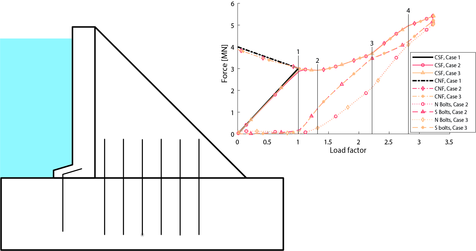
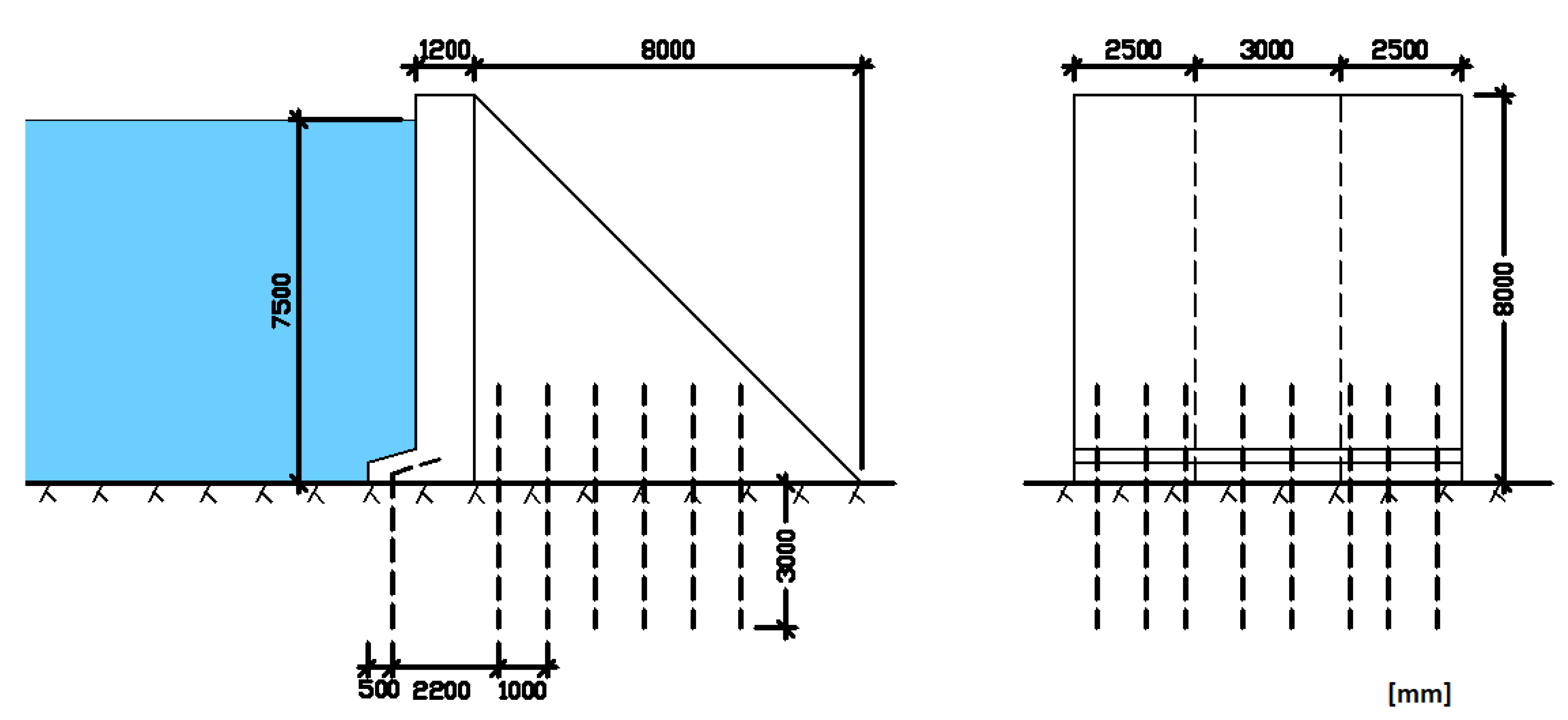
To study how rock bolts affect the failure process of a small concrete dam, the research in this paper was performed as a case study, where one monolith from an 8 m high buttress dam in northern Sweden was used as the studied object. The dam is a small buttress monolith anchored with a total of 20 rock bolts. The front plate has a width of 8 m and a constant thickness of 1.2 m, with a 1 m wide dam toe and the buttress wall has a constant thickness of 3.0 m. Each rock bolt is drilled 3 m into the rock and embedded 2 m in the concrete. The bolts are ribbed steel rebars with a diameter of 25 mm. Eight of the bolts are located under the front plate in the upstream dam toe, and the remaining twelve are placed in two rows beneath the buttress wall. The dimensions of the monolith and the position of the bolts are shown in Figure 1. The bridge on the dam crest was not included in the analysis to simplify the geometry.
2.1. Analyzes
Analytical stability calculations and simulations were performed for three cases to compare different assumptions regarding the bolts:
- Case 1:
- Without bolts
- Case 2:
- Bolts with a fixed attachment.
- Case 3:
- Bolts with deformable attachment.
Case 1 serves as a reference and makes it possible to estimate the influence of the rock bolts compared to a dam without bolts. Cases 2 and 3 include rock bolts, but the analyses were performed with different assumptions for the bolt attachment. In Case 2, the bolts were anchored with a fixed stiff horizontal support without consideration to deformation in the grout and rock. In the hand calculation, that means the capacity of the bolt in the radial displacement was calculated using Equation (12). In the simulation, a restrained horizontal boundary condition was applied on the embedded part of the rock bolt element. In Case 3, the deformation in the grout and rock during shear loading was considered. The capacity of the bolts in the analytical stability evaluation was calculated using Equation (11). In the simulation, the rock bolt model presented in Section 2.4.2 was used as the horizontal support for the bolts.
2.2. The Dam
2.2.1. Material Properties
2.2.2. Loads
Hydrostatic pressure, uplift pressure and ice load was included. The water level was assumed to be 0.5 m below the dam crest, and the uplift pressure was applied with a linear variation from full water head at the upstream edge to zero at the downstream edge. An ice load of 100 kN/m was applied as an evenly distributed pressure on a 0.6 m high surface just under the water level.
2.2.3. FE-Model
The FE-model includes the dam and part of the surrounding rock, see Figure 2. All the numerical analyses were performed with Abaqus [9], version 2018 with the standard implicit solver. The dam and rock were modelled with 8-node linear brick elements with reduced integration and hourglass control (element C3D8R in Abaqus).
The average element size was 0.2 m for the dam and 0.25 m for the rock, meaning that a total of 32,640 elements were used for the dam and 40,960 elements for the rock. In the model, the boundary condition was applied to the rock by prohibiting displacements perpendicular to each side at all outer boundaries of the rock, except the top surface, see Figure 2. The rock was included in the model with the length 20.0 m in the upstream-downstream direction, the width 8 m in the direction perpendicular to the cross-section of the dam, and the height 4.0 m. The purpose of including the rock in the model is to account for the friction at the interface and the dam is held in place by frictional forces in the interface between the dam and the foundation. The properties of the interface between dam and rock was considered according to the Swedish regulations for dam safety [2]. In the tangential direction a friction contact model was introduced where the friction coefficient was set to 1.0 and was kept constant throughout the analysis. The contact in the normal direction was modelled as a hard contact in compression but allowed separation due to tensile forces; no cohesive bond in the concrete-rock was considered.
2.3. Stability Analyses of Dams
2.3.1. Analytical Stability Analyses
The analytical stability calculations were performed according to the Swedish guidelines, where a strong emphasis is put on the sliding and overturning failure modes [2]. In the dam safety assessments, it must be shown that concrete dams are safe against sliding and overturning failure modes. The stability analyses are performed with hand calculation methods, based on the force equilibrium of a rigid body.
The analytical calculations require that force resultant and lever arm are calculated for all loads, including self-weight. For sliding, the safety factor is defined as the ratio between the maximum friction force in the interface between concrete and rock and the acting forces parallel to the sliding surface (i.e., the horizontal forces).
where, is the coefficient of friction in the interface, is the sum of all horizontal forces (i.e., parallel to the sliding plane) and are the sum of all vertical forces.
The safety factor for overturning is defined as the ratio between the stabilizing moments and the de-stabilizing moments, .
The moments were calculated with the dam toe as the axis of rotation.
2.3.2. Numerical Failure Analyses
There are two basic methods for simulating the failure of a structure; strength reduction and overload [10]. In the strength reduction method, normal loads are applied to the structure and thereafter are the strength reduced until failure occurs. In the overload method, normal loads are applied to the structure, and these loads are thereafter increased until a failure occurs. To achieve safety factors that are comparable with the analytical calculations, the failure analyses were performed with the increased density approach presented by [10,11]. In the increased density approach, the first step of analysis includes all design loads. In subsequent steps, all the destabilizing loads are gradually increased with a load factor of until failure occurs. The load factor that occurs at the point of failure is defined as the factor of safety of the structure, S.
where is the design load. The non-linearities considered in the analyses are the interface properties between rock and dam; the non-linear material behaviour of the steel; and the non-linear anchoring of the bolts caused by failure in the grout (incl. its interface to rock or bolt).
2.4. Design of Rock Bolts for Dam Stability
2.4.1. Analytical
Two kinds of movement occur in bolted joints; the opening of the joint in the normal direction (perpendicular to the joint plane) and shear displacement in the interface plane. In design, a rock bolt loaded in the normal direction is assumed to behave as the weakest link system. In tension, the load capacity of a bolt corresponds to the lowest failure load of [1];
- Cone failure in the rock
- Cone failure in the concrete
- Adhesive failure between rock and grout.
- Adhesive failure between steel and grout.
- Adhesive failure between concrete and steel.
- Steel failure.
The cone failure in rock and concrete occurs when a volume theoretically shaped as a cone is pulled out. There are several ways to calculate the capacity of the cone. If the shear capacity of the material is neglected, the failure load can be calculated as the weight of the assumed cone according to Equation (4).
where is the load that mobilises a rock volume with the angle and height equal to the embedment depth of the rock bolt in the rock, ; and is the unit weight of the rock.
The adhesive bond failures occur when the stress reaches the maximum allowed bond stress for the contact surface, as mentioned above, the failure can occur in three interfaces where the load capacity for each interface is calculated as.
Here, is the diameter of the rock bolt, the diameter of the hole and is the embedded length in the concrete. For the maximum allowed stress in the interface, , the subscript RG, GB and CB denotes the interface Rock-Grout, Grout-Bolt and Concrete-Bolt, respectively.
The capacity of the bolt is equal to the ultimate bond strength times the cross-sectional area.
The anchoring capacity of the rock bolt for an orthogonal load is the lowest value of the failure modes listed above.
For a rock bolt loaded in the shear plane, displacements activate forces in the bolt and the failure then depends on the interaction between steel, rock and grout and their non-linear material behaviour. As forces build-up, the bolt holds the joint together, increasing the normal stress in the interface. This extra normal stress is added to the shear capacity of the joint due to friction, and its effect can exceed the shear capacity of the bolt itself. The resistance of the rock bolt to withstand shear deformations depends on the stiffness and compressive strength of the surrounding materials, i.e., grout, rock and concrete. The contribution of the bolt to the shear capacity of a joint may exceed the shear capacity of the steel material. This contribution consists of a dowel effect and a friction effect [8,12,13]. The dowel effect is due to the contribution from shear forces in the rock bolt while the friction effect is due to the increased friction in the joint caused by increased normal forces in the interface.
If the surrounding materials have high stiffness, then no bending of the bolt will occur. Instead, localized shear deformation occurs in the contact zone. This localized shear deformation is called the dowel effect and is illustrated in the left sketch in Figure 3. In hard rock, the mobilized shear stress becomes high enough to cut the bolt at low degrees of deformation before any significant tensile stresses have been developed. According to [14], this deformation could be as small as 1–3 mm. The dowel capacity of a bolt is equal to the shear strength times the cross-sectional area.
If the stiffness and compressive strength of the surrounding materials is low, then the bolt will gradually deform and crush the surrounding materials, and a tensile load component will develop, forming a crank shape [15]. In that case, the bolt will fail due to the fact that the tensile strength is exceeded giving a high deformation at failure. This deformation is usually in the order of the bolt diameter, which means that full strength is not mobilized until deformations of around 20 to 30 mm have occurred [15]. In addition, the contact zone between concrete and rock is not a smooth surface in reality. The roughness of the contact zone will give rise to a dilatation which will lead to tensile stresses in the bolt. The friction capacity of a rock bolt can be assumed to be equal to the tensile capacity. Hence, it can be determined from Equation (9).
If the interface between the rock and the dam is intersected by rock bolts, these will result in additional shear strength. When the sliding plane is subjected to shear deformation, the roughness will give rise to a dilatation which leads to tensile stresses in the bolt. The vertical component of the tensile stress in the bolt gives rise to a corresponding additional normal stress on the weakness plane, which leads to an increased shear strength for the weakness plane. Since the degree of mobilized tensile and shear stresses are often unknown in analytical calculations, it is generally assumed that the bolt either works as a dowel according to Equation (10) so that Equation (1) is rewritten as
or that only tensile stresses are developed according to Equation (9).
where, or is the contribution from all rock bolts crossing the sliding plane.
In an overturning failure mode, analytical calculations are performed where it typically is assumed that the dam will rotate around the downstream toe. A moment balance equation is defined for the stabilizing and overturning moments. The rock bolts will introduce additional resistance to the stabilizing moment. As described earlier, the load capacity of the rock bolts can be defined as the minimum of all potential failure modes. In the conventional design, the rock bolts are however designed to result in a steel failure, due to its ductile behaviour.
2.4.2. Numerical Rock Bolt Model
Two approaches are used when analysing rock bolt by numerical methods; explicit [13,16,17], and implicit [18,19,20,21] methods. In the implicit method, the rock bolts contribution to the joint is smeared over the rock mass by adding it directly in the constitutional law of the rock or joint. This approach is used to simulate larger civil engineering problems where it is inconvenient to model each rock-bolt. Contrary, the rock bolt is modelled as an own part in the explicit method. Therefore, the explicit method allows a more detailed study of their behaviour. To simulate the behaviour of grouted rock bolts under shear using explicit models, the bolt, grout, and the nonlinear material behaviour and interactions between interfaces is often treated with a high level of detail, see for example [17,22,23]. These types of analyses are therefore computational demanding and are in most cases limited to the simulation of a single bolt. For large concrete structures anchored by rock bolts, it is desirable to use a simpler rock bolt model. Using a detailed simulation of a rock bolt to a dam monolith with 20–50 anchors involves high computational costs. As an alternative, a simplified approach is used in this paper, where the bolt is modelled with an explicit model where the bolt is represented with a beam element and the attachment to the rock with springs. For the axial behaviour, the principle of bond stress-slip relationship from [24,25] was used. The attachment to the rock is modelled using non-linear springs. The springs were modelled with connector elements with a predefined force-displacement curve in Abaqus. The anchorage of bolts are modelled with a bond stiffness-displacement relationship consisting of four parts, according to Equation (13) where is the foundations stiffness (N/m) and u the displacement.
The input for the model is the maximal force , the residual force stress ; the three displacements ; and the parameter .
The stiffness is recalculated to a force-displacement relationship at each node of the bolt element,
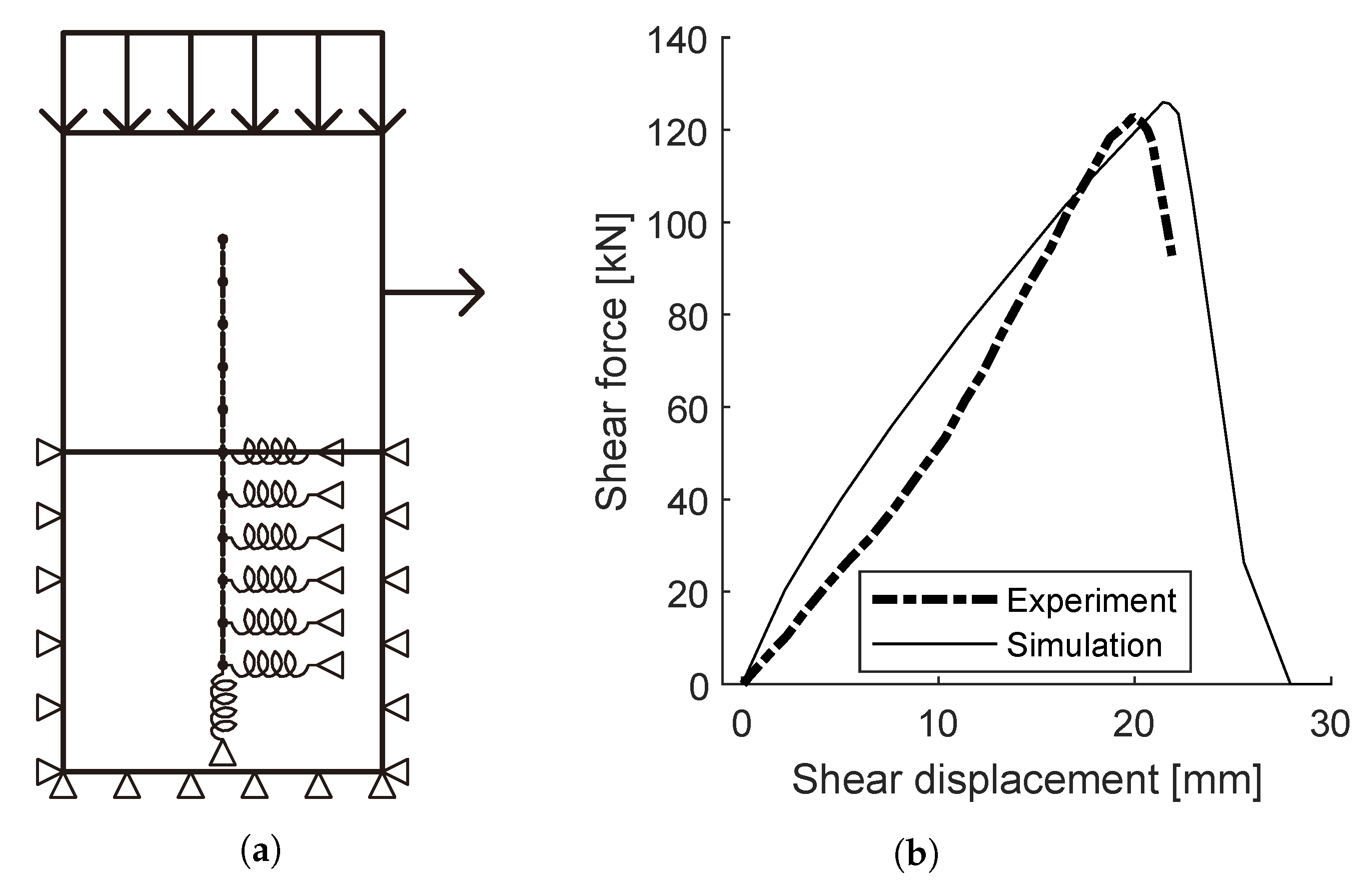
where is the force in the spring and h the length of the mesh element. This force-displacement relationship was used to model both the displacement in the axial and radial direction of the bolt. The rock bolt is considered in the modelled where a three-dimensional beam element with both transitional and rotational degrees of freedoms represents the bolts. A spring is attached to the bolt at every node, and on the other end of the spring, a fixed displacement boundary condition is applied. The rock and the springs are therefore not connected, and the purpose of including the rock in the model is to account for the friction at the interface. The properties for the axial stiffness was chosen in accordance with [26], who performed calibrations of the spring stiffness in the axial direction on pull out test performed by [14]. The radial stiffness was calibrated based on shear tests on 16 mm rock bolts installed in granite blocks in size [14]. A test with an untensioned bolt installed perpendicular to the shear plane was chosen for the calibration. Figure 4a shows the layout of the FE-model and the input data is presented in Table 2. After a mesh size convergence study, an element size of one-tenth of the embedment length was used for all three parts. The boundary condition was applied to the rock by prohibiting displacements perpendicular to each side at all outer boundaries of the rock, except for the top surface, as seen in Figure 4a. The same contact properties were used for the interface as described above for the simulations of the dam where the friction coefficient was changed to correspond to the material data given in Table 2. A vertical pressure was applied on the top surface with magnitude in accordance with Table 2.
Figure 4b shows the force-displacement curve for the simulation and test with the best fit.
Table 3 presents the forces used for the two directions.
3. Results
Table 4 presents the safety factors from analytic stability calculations and simulations. The bolts significantly increase the factor of safety in all analyses. For overturning, the safety factor is almost the double for Case 2 and 3 with bolts compared to Case 1 without bolts. For sliding, the inclusion of rock bolts increases the safety factor by 70% and 120% for treating the bolts as dowels or tension, respectively. The difference between the safety factor for cases 1 and 2 or 3 is even more significant in the simulations. Overall, the passive bolts account for somewhere between 40% and 75% of the load capacity of the dam.
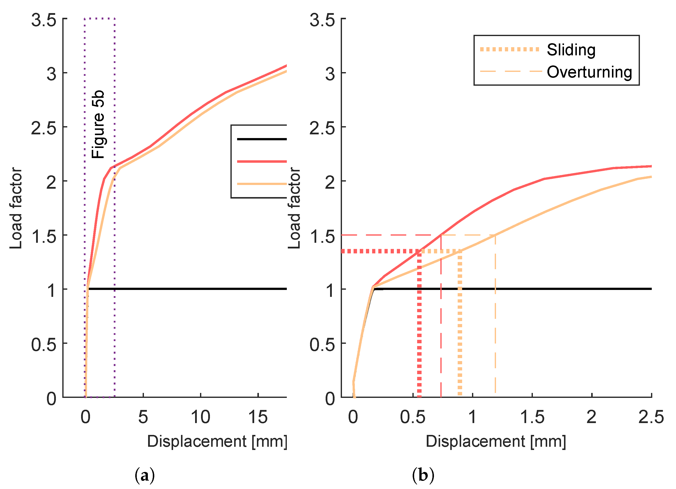
Figure 5 shows the crest displacement vs load factor (defined in Section 2.3.2) for the simulation. Case 1 shows small linear displacements until failure occurs. Since the friction coefficient is set to 1.0, failure occurs when the required shear force is greater than the normal force. Whe the simulation reaches the failure load, the solver cannot find an equilibrium since the dam starts to slide. This sliding is difficult to capture with a load controlled static simulation. Hence, this non-convergence was interpreted as an increase in sliding displacement under constant loads, i.e., what would be characterized as a failure. The crest displacement up to this load level is small and identical for all the models.
At the failure load level for Case 1, the bolts are activated in Cases 2 and 3, and thereby, the load can be further increased. In these models, the behaviour differs between these two cases. In Case 2, the forces in the bolts can increase immediately, while Case 3 require larger displacements in the rock-dam interface before the load in the bolts increases. Already for small displacements, significant strains develop in the bolts. This leads to a significant increase in the bearing capacity of the bolts even for a small displacement of the dam. As the steel yields, the displacements increases and a large displacement occurs before the ultimate capacity of the dam is reached. Case 3 shows a similar failure process but with larger displacements. Since the springs allow displacement of the horizontal support of the bolts, larger deformations of the dam are required for the same load. In the initial state, displacements occur in the spring before sufficient resistance is developed so that the steel starts to deform. Thereafter the load-deformation curve follows a path similar to that of Case 2. Both models fail to converge at approximately the same load level when the ultimate stress for the bolts are reached in all bolts, and this non-convergence was interpreted as a failure. The displacement required to increase the load factor from 1.0, the failure of the unanchored dam, to 1.35 ( the required safety factor for sliding according to the Swedish guidelines [2]) is 0.55 mm and 0.89 mm for Case 2 and Case 3, respectively. To corresponding displacements to achieve a bearing capacity that fulfils the load factor required for the overturning failure mode is 0.74 mm and 1.2 mm.
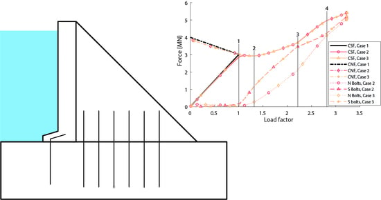
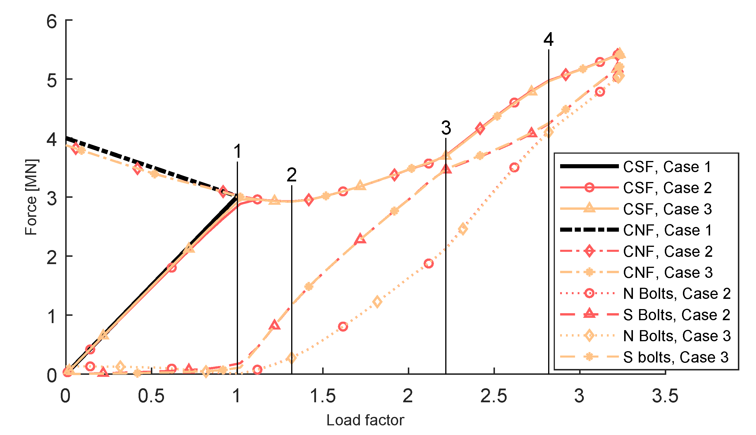
Figure 6 shows the vertical and horizontal reaction forces, i.e., the contact forces in the surface between rock and dam and the total reaction force for all the bolts. At load factor zero (only the dead load applied) the shear force on the surface is approximately zero. As the water pressure increases, the shear force increases. For the normal forces, the relationship is the opposite. At load factor zero, the total normal force is equal to the dead load, and the normal force thereafter decreases linearly as the uplift pressure increases.
During the progressive failure, the following notable events occur at the points marked in Figure 6.
- The failure load for Case 1, the model without bolts. From the red dashed line with triangles in Figure 6, representing the horizontal forces in the bolts in the fixed model, it can be seen that there are horizontal forces present in the bolts before this load level. This is not the case for the orange dashed line with asterisks representing the shear forces in the bolt in the Case 3 model, where the bolt forces first occur after this load level. The difference in shear force in the bolts between the Case 2 and Case 3 models is at this point approximately 100 kN.
- The initial linear slope in the force-displacement curve for Case 3 ends shortly after a minimum in the interface forces. After this point, the normal forces in the bolts are large enough to pull the dam towards the rock and create a frictional effect. The increasing load is carried by a combination of increasing forces in the concrete-rock interface and in the bolts.
- A change in failure mode occurs as the increasing load is carried by an increasing proportion by normal force in the bolts.
- Another change in behaviour of the dam, from here to the failure, is the increase in load capacity mainly due to increased forces in the bolts.
4. Discussion
Previous studies [4,6] and Table 4 shows that rock bolts may have a significant impact on the stability of small concrete dams. Inclusion of rock bolts in stability calculations can make the difference between not satisfying the design criteria and being able to withstand the design loads. Vice versa, excluding the rock bolts from the safety assessment of small dams, means that significant a part of the load-bearing system is neglected. This can also mean that an incorrect failure mode is assumed and that the dam is thereby strengthened in a suboptimal way. For example, post-tensioned anchorage may be installed to prevent an overturning failure where a backfill to increase the sliding resistance would be the measure that most increases the overall dam safety. Including the effect of rock bolts in the stability, analyses are therefore of great practical use with decreasing costs, from both an economical and an environmental aspect.
However, the bolts do not contribute to the load-bearing until a displacement occurs in the dam-rock interface. The results presented in Figure 5 indicates that a significant part of the additional bearing capacity is achieved already at relative small displacements. The displacement required to increase the load factor from 1.0 (the failure of the unanchored dam) to a load factor that fulfils all stability requirements is 1.2 mm. If dilatation and unevenness in the dam-rock interface were considered, this displacement would be even smaller. A common definition of a dam failure is: “Collapse or movement of a part of a dam or its foundation, so that the dam cannot retain water. In general, a failure results in the release of large quantities of water, imposing risks on the people or property downstream” [27]. Such release of water is highly unlikely to occur as a result of this magnitude of displacement.
The interaction between forces in the interface and the bolts are presented in Figure 6. For a dam, the friction effect of the bolts, i.e., the ability of a bolt to hold the interface together and thereby increase the friction force in the interface is significant. The bolts prevent the dam from lifting, leading to a maintained and even increased restraining friction force in the concrete-rock interface. After activation of the bolts, the normal force and corresponding shear force in the interface increase, although the resultant of the applied vertical load decreases as the uplift pressure increases. In the simulations, the up-lift pressure increases as the load factor increases. In reality, the ability of the bolts to hold the interface together may reduce or prevent water flow in the joint. The positive effect of rock bolts under the front plate is therefore likely to be underestimated in the simulations. The shear forces in the bolts occur at smaller displacements, and during the loading process, they are significantly higher than the normal forces in the bolts. However, the results indicate that the bolts are carrying a combination of tensile and shear forces. This implies that analytical calculations should preferably be based on the load-carrying capacity of combined normal and shear forces.
In the case study, a flat interface between rock and concrete and a constant friction coefficient was used, with cohesion neglected. In reality, the friction coefficient decreases from a static to a kinematic coefficient after the initial movement breaks the bonds created by asperities in the interface. The same reasoning can be used for cohesion. After the movement required to activate the bolts, the cohesive bond in the interface will be lost. The combination of cohesive bond failure along with the decrease in friction angle is not trivial and, for the purpose of studying the rock bolts impact, that issue was excluded. To simulate the behaviour of a grouted rock bolt, a model that includes deformation both in grout and in rock should be used. Neglecting these deformations leads to an inaccurate estimation of the failure behaviour for an anchored structure, where the bolt forces under small displacements are overestimated.
5. Conclusions
The effect of passive rock bolts contribution to the stability of small concrete dams has been studied. This has been studied through traditional analytical stability calculations and FE-simulations of the failure progress that allows a more detailed study of the distribution in load carrying capacity between the bolts and the contact force in the rock-dam interface, during the failure progression.
The analytical stability calculations confirm the background to this study and show that the inclusion of rock bolts can make the difference between a dam that is deemed not safe and one that with great margin fulfil the design criteria. Depending on the method of analysis, the rock bolts contribute with 40–75% of the total load-carrying capacity of the dam. Current design criteria hence neglect a significant part of the load-bearing system for small dam anchored with rock bolts.
Simulation of the failure process of an anchored concrete dam shows that the forces in the bolts are negligible up to the load level at which a failure occurs for the unanchored anchored dam. Thereafter, a displacement occurs in the contact surface, and the rock bolts are activated. Initially, the horizontal forces in the rock bolts increase but relatively early, the rock bolts help to hold the contact surface together so that the frictional force in the interface can be increased. The rock bolts increase the load-bearing capacity of the dam, partly through anchorage forces, but also by keeping the contact surface between rock and concrete together and thereby increase the shear capacity of the interface. The simulation shows that the contribution from passive rock bolts at 0.74 mm and 1.2 mm displacement in the dam-rock interface increases the load-carrying capacity sufficient to fulfil the required safety for sliding and overturning failure, respectively. Such displacement is unlikely to lead to an uncontrolled release of water. The current requirement for a safety factor of at least 1.0 without bolts is a sound criterion for the serviceability limit state, but it is overly conservative not to include the bolts in the ultimate failure capacity.
This study address one of the two major concerns regarding passive rock in dam safety presented in the introduction. The concern about the condition of inaccessible rock bolts under concrete dams with regards to degradation remains, and should be given further attention. In the case study, a flat interface between rock and concrete, and a constant friction coefficient was used, with cohesion neglected. In further studies, the failure of a dam with regard to the interaction between cohesive bond failure, dilatation, friction coefficient decrease and rock bolt should be studied.
Author Contributions
The authors confirm contribution to the paper as follows; conceptualization, R.M. and R.H.; methodology, R.H. and R.M.; software, R.H.; validation, R.H., R.M. and A.A.; formal analysis, R.H.; investigation, R.H., R.M.; resources, R.M. and A.A.; data curation, R.H.; writing original draft preparation, R.H.; writing review and editing, R.H., R.M. and A.A.; visualization, R.H.; supervision, R.M. and A.A.; project administration, R.M.; funding acquisition, R.M. All authors have read and agreed to the published version of the manuscript.
Funding
This work was carried out as a part of “Swedish Hydropower Centre—SVC”. SVC has been established by the Swedish Energy Agency, Elforsk and Svenska Kraftnät together with Luleå University of Technology, KTH Royal Institute of Technology, Chalmers University of Technology and Uppsala University. www.svc.nu.
Conflicts of Interest
The authors declare no conflict of interest. The funders had no role in the design of the study; in the collection, analyses, or interpretation of data; in the writing of the manuscript, or in the decision to publish the results.
References
- Ekström, T.; Hassanzadeh, M.; Janz, M.; Sederholm, B.; Stojanovic, B.; Ulriksen, P. Condition Assesment of Rock Anchors in Dams; Technical Report; Elforsk: Stockholm, Sweden, 2013. [Google Scholar]
- RIDAS. Swedish Hydropower Companies Guidelines for Dam Safety, Application Guideline 7.3 Concrete Dams; Technical Report; Svensk Energi: Stockholm, Sweden, 2017. [Google Scholar]
- NVE. Guidelines for Concrete Dams; Technical Report; Norges Vassdrags- og Energidirektorat: Oslo, Norway, 2005.
- Larsson, C. Investigation and Testing of Rock Bolts at Hotagen Power Station; Technical Report; Elforsk: Stockholm, Sweden, 2009. [Google Scholar]
- Hellgren, R.; Rios Bayona, F.; Malm, R.; Johansson, F. Pull-out tests of 50-year old rock bolts. In Proceedings of the International Symposium “Appropriate Technology to Ensure Proper Development, Operation and Maintenance of Dams in Developing Countries”, Johannesburg, South Africa, 18 May 2016; pp. 263–272. [Google Scholar]
- Berzell, C. Load Capacity of Grouted Rock Bolts in Concrete Dams. Master’s Thesis, KTH Royal Institute of Technology, Concrete Structures, Stockholm, Sweden, 2014. [Google Scholar]
- Westberg Wilde, M.; Johansson, F. Probabilistic Model Code for Concrete Dams; Technical Report; Energiforsk: Stockholm, Sweden, 2016. [Google Scholar]
- Malm, R.; Johansson, F.; Hellgren, R.; Ríos Bayona, F. Load Capacity of Grouted Rock Bolts Due to Degradation; Technical Report; Energiforsk: Stockholm, Sweden, 2017. [Google Scholar]
- Dassault Systemes. Abaqus CAE (version 2017) 2017. Available online: https://www.3ds.com/products-services/simulia/products/abaqus/abaquscae/ (accessed on 27 May 2019).
- Malm, R. Guideline for FE Analyses of Concrete Dams; Technical Report; Energiforsk: Stockholm, Sweden, 2016. [Google Scholar]
- Nordström, E.; Malm, R.; Johansson, F.; Ligier, P.L.; Øyvind, L. Betongdammars Brottförlopp Energiforsk Rapport 2015:122; Failure of Concrete Dams—Literature Review and Potential for Development; Technical Report; Energiforsk: Stockholm, Sweden, 2015. [Google Scholar]
- Bjurstrom, S. Shear strength of hard rock joints reinforced by grouted untensioned bolts. In Proceedings of the Third Congress of the International Society for Rock Mechanics, Denver, CO, USA, 1–7 September 1974; Volume 2, pp. 1194–1199. [Google Scholar]
- Spang, K.; Egger, P. Action of fully-grouted bolts in jointed rock and factors of influence. Rock Mech. Rock Eng. 1990, 23, 201–229. [Google Scholar] [CrossRef]
- Bjurström, S. Bolted Hard Jointed Rock; Technical Report; The Swedish Fortifications Agency: Stockholm, Sweden, 1973.
- Stille, H. Keynote Lecture: Rock Support in Theory and Practice. In Rock Support in Mining and Underground Construction; CRC Press: Boca Raton, FL, USA, 1972; pp. 421–437. [Google Scholar]
- Chen, S.H.; Qiang, S.; Chen, S.F.; Egger, P. Composite Element Model of the Fully Grouted Rock Bolt. Rock Mech. Rock Eng. 2004, 37, 193–212. [Google Scholar] [CrossRef]
- Jalalifar, H.; Aziz, N. Experimental and 3D Numerical Simulation of Reinforced Shear Joints. Rock Mech. Rock Eng. 2010, 43, 95–103. [Google Scholar] [CrossRef]
- Chen, S.H.H.; Egger, P. Three dimensional elasto-viscoplastic finite element analysis of reinforced rock masses and its application. Int. J. Numer. Anal. Methods Geomech. 1999, 23, 61–78. [Google Scholar] [CrossRef]
- Stille, H.; Holmberg, M.; Nord, G. Support of weak rock with grouted bolts and shotcrete. Int. J. Rock Mech. Min. Sci. 1989, 26, 99–113. [Google Scholar] [CrossRef]
- Chen, S.H.; Yang, Z.M.; Wang, W.M.; Shahrour, I. Study on rock bolt reinforcement for a gravity dam foundation. Rock Mech. Rock Eng. 2012, 45, 75–87. [Google Scholar] [CrossRef]
- D’Amato, M.; Braga, F.; Gigliotti, R.; Kunnath, S.; Laterza, M. Validation of a modified steel bar model incorporating bond-slip for seismic assessment of concrete structures. J. Struct. Eng. 2012, 138, 1351–1360. [Google Scholar] [CrossRef]
- Grasselli, G. 3D behaviour of bolted rock joints: Experimental and numerical study. Int. J. Rock Mech. Min. Sci. 2005, 42, 13–24. [Google Scholar] [CrossRef]
- Kilwic, A.; Yasar, E.; Celik, A.G. Effect of grout properties on the pull-out load capacity of fully grouted rock bolt. Tunn. Undergr. Space Technol. 2002, 17, 355–362. [Google Scholar] [CrossRef]
- Bahrani, N.; Hadjigeorgiou, J. Explicit reinforcement models for fully-grouted rebar rock bolts. J. Rock Mech. Geotech. Eng. 2017, 9, 267–280. [Google Scholar] [CrossRef]
- Fib. Model Code for Concrete Structures 2010; Technical Report; Wilhelm Ernst & Son: Lausanne, Switzerland, 2010. [Google Scholar]
- Sjölander, A.; Hellgren, R.; Ansell, A. Modelling aspects to predict failure of a bolt-anchored fibre reinforced shotcrete lining. In Proceedings of the Eight International Symposium on Sprayed Concrete—Modern Use of Wet Mix Sprayed Concrete for Inderground Support, Trondheim, Norway, 11–14 June 2018; pp. 278–292. [Google Scholar]
- ICOLD. Dam Failures—Statistical Analysis Bulletin 99; Technical Report; International Commission on Large Dams (ICOLD): Paris, France, 1995. [Google Scholar]
Figure 1.
Sketch of the buttress monolith used as a case study, and the location of the 20 rock bolts.
Figure 1.
Sketch of the buttress monolith used as a case study, and the location of the 20 rock bolts.

Figure 2.
Static system with boundary conditions used in the numerical calculations and applied loads.
Figure 2.
Static system with boundary conditions used in the numerical calculations and applied loads.

Figure 3.
Illustration of the dowel effect (left) and crushing of surrounding material (right).

Figure 4.
(a) Sketch of the principal design of the simulation models and shear tests, (b) Force displacement curves from tests performed by [14] and corresponding simulations.
Figure 4.
(a) Sketch of the principal design of the simulation models and shear tests, (b) Force displacement curves from tests performed by [14] and corresponding simulations.

Figure 5.
Load factor as a function of crest displacement, a load factor up to 1.0 includes all design loads while only the destabilizing loads are amplified for greater load factors. Case 1 is without bolts; Case 2—bolts with a fixed attachment and Case 3—bolts with deformable attachment. (a) The complete load-displacement curve, and (b) load-displacement curve for the initial part of the curve with the the required safety factor for sliding (1.35) and overturning (1.5) according to the Swedish guidelines for dam safety marked [2].

Figure 6.
Shear and normal reaction forces as a function of load factor presented as forces in the bolts and on the surface of the dam-rock interface. The notation CNF is the contact normal force, and CSF is the contact shear force. N and S are normal and shear forces in the bolts, respectively. Case 1 is without bolts; Case 2 bolts with a fixed attachment and Case 3 bolts with deformable attachment.


Table 1.
Material properties used for the case study.
| Variable | Value | Unit |
|---|---|---|
| Density, concrete | 23 | |
| Elastic modulus, concrete | 30 | GPa |
| Density, rock mass | 26.5 | |
| Elastic modulus, rock | 30 | GPa |
| Adhesion grout-rock | 2.0 | MPa |
| Adhesion grout-steel | 1.2 | MPa |
| Adhesion concrete-steel | 3.0 | MPa |
| Elastic modulus, Steel | 200 | GPa |
| Ultimate strain, Steel, | 0.15 | - |
| Possion’s ratio, Steel | 0.30 | - |
| Yield strength, Steel | 370 | MPa |
| Ultimate strength, Steel | 600 | MPa |
Table 2.
Material properties for the shear test from [14], that was used to calibrate the radial spring stiffness.
Table 2.
Material properties for the shear test from [14], that was used to calibrate the radial spring stiffness.
| Variable | Value | Unit |
|---|---|---|
| Diameter rock bolt | 16 | mm |
| Diameter drilled hole | 32 | mm |
| Yield stress | 370 | MPa |
| Ultimate stress | 600 | MPa |
| Ultimate strain | 0.05 | - |
| Rock compressive strength | 162 | MPa |
| Rock elastic modulus | 69 | GPa |
| Friction angle along the shear plane | 31 | - |
| Applied normal stress | 4.0 | MPa |
Table 3.
The properties used for the attachment spring.
| Model | Unit | Axial | Radial |
|---|---|---|---|
| N/mm | 120 | ||
| mm | 0 | 0 | |
| mm | 6 | 20 | |
| mm | 35 | 25 | |
| mm | 36 | 26 | |
| 0.4 | 0.8 |
Table 4.
Calculated factor of safety for analytical stability calculations and simulations.
| Analytic | Simulations | ||
|---|---|---|---|
| Overturning | Sliding | ||
| Case 1, without bolts | 1.35 | 1.03 | 1.00 |
| Case 2, with bolts, dowel | 2.46 | 1.73 | 3.22 |
| Case 3, with bolts, tension | 2.46 | 2.24 | 3.23 |
© 2020 by the authors. Licensee MDPI, Basel, Switzerland. This article is an open access article distributed under the terms and conditions of the Creative Commons Attribution (CC BY) license (http://creativecommons.org/licenses/by/4.0/).
Share and Cite
MDPI and ACS Style
Hellgren, R.; Malm, R.; Ansell, A. Progressive Failure Analysis of a Concrete Dam Anchored with Passive Rock Bolts. Infrastructures 2020, 5, 28. https://0-doi-org.brum.beds.ac.uk/10.3390/infrastructures5030028
AMA Style
Hellgren R, Malm R, Ansell A. Progressive Failure Analysis of a Concrete Dam Anchored with Passive Rock Bolts. Infrastructures. 2020; 5(3):28. https://0-doi-org.brum.beds.ac.uk/10.3390/infrastructures5030028
Chicago/Turabian StyleHellgren, Rikard, Richard Malm, and Anders Ansell. 2020. "Progressive Failure Analysis of a Concrete Dam Anchored with Passive Rock Bolts" Infrastructures 5, no. 3: 28. https://0-doi-org.brum.beds.ac.uk/10.3390/infrastructures5030028