Failures of the Cast-Iron Columns of Historic Buildings—Case Studies †


Department of Concrete Structures, Lodz University of Technology, 90-924 Łódź, Poland
*
Author to whom correspondence should be addressed.
†
The paper includes some selected issues presented during REHABEND 2020 Congress.
Infrastructures 2020, 5(9), 71; https://0-doi-org.brum.beds.ac.uk/10.3390/infrastructures5090071
Submission received: 27 July 2020
/
Revised: 19 August 2020
/
Accepted: 30 August 2020
/
Published: 2 September 2020
(This article belongs to the Special Issue Selected Papers from the REHABEND 2020 Congress)
Abstract
:Selected technical problems related to the rehabilitation of cast-iron columns in structures from the turn of the 19th and 20th century are discussed in the paper. Lack of contemporary standard regulations related to the design of cast-iron structures is a significant problem in the design works and experimental investigations on cast-iron columns are frequently required. The paper presents results of the tests concerning principal properties of cast-iron—strength and deformability. The historical design principles are discussed in the light of the results of experimental investigations. As it was demonstrated, the actual load-carrying capacities of cast-iron columns may exceed by several times the values resulting from the 20th century design rules. The conservatism of the design principles resulted, however, from the material uncertainties—lack of homogeneity and hidden defects of the cast-iron. Selected examples of failures of cast-iron columns from 19th-century structures such as post-industrial buildings and engineering structures are discussed. They resulted from errors made during adaptation works. The reasons for these failures and considered methods of repairing the structures are presented.
1. Introduction
Today, more and more initiatives aimed at revitalizing degraded urban areas are being undertaken. The revitalization of historic post-industrial buildings consists of adapting them for new functions and incorporating them into the contemporary culture, with maximum respect for the existing architectural form and building structure. These actions are often accompanied by problems related to the assessment of the load-carrying capacity of the elements made of materials for which there is no certainty about strength characteristics [1]. One example of such elements are cast-iron columns, commonly used in industrial facilities erected at the turn of the 19th and 20th century in large parts of Europe, including Poland.
Gray cast-iron is an alloy of iron with carbon in the form of graphite. Depending on the morphology of graphite, gray cast-iron (graphite in form of flakes), vermicular cast-iron, or ductile cast-iron can be distinguished. Contrary to ductile cast-iron, known since the middle of the 20th century, gray cast-iron, commonly used for making cast-iron columns, was characterized by relatively low tensile strength and low resistance to impact loads. The reasons for that should be sought primarily in the structure of cast-iron, in which nodules or flaky particles of graphite can be distinguished. The graphite has no appreciable strength, and therefore each graphite inclusion is detrimental to the mechanical properties as it acts as preexisting notches at which stresses concentrate causing fracture of the material.
Cast-iron manufactured in the second half of the 19th century was characterized by the following chemical composition [2]: carbon (3.2 ÷ 3.3%); silicon (0.9 ÷ 1.1%); phosphorus (0.2 ÷ 0.3%); manganese (1.1 ÷ 1.7%); and sulfur (0.05 ÷ 0.07%). Initially, it was mainly produced with the Bessemer process. Due to the imperfections of the casting technology of that time, cast-iron was characterized by very differentiated properties, which were not regulated by any standard provisions. Cast-iron products were often characterized by defects, which were manifested by the occurrence of various types of voids (bubbles, nitrogen blowholes), microcracks (as a result of shrinkage), and impurities in the form of inclusions (e.g., furnace slag, sand; see Figure 1). Due to the high uncertainty regarding the mechanical properties of cast-iron, before proceeding to the design works it is necessary to undertake material tests. Cast-iron has a compressive strength that significantly exceeds its tensile strength, and is therefore a brittle material.
The issue of assessing the load-carrying capacity and suitability for new purposes of the existing cast-iron columns has been the scope of many previous considerations. The first extensive experimental studies on cast-iron columns were conducted in the second half of the 19th century by Hodgkinson [3] and Tetmajer [4] and concerned elements with the solid cylindrical, hollow cylindrical, and uniform square cross-section. On their basis, the first relationships describing the permissible stress including shape (slenderness) of the columns were formulated. Moreover, Ludwig von Tetmajer [4] determined the tensile strength and modulus of elasticity of cast-iron, which were equal to approximately Rt = 125 MPa and E = 100 GPa, respectively.
Rondal and Rasmusen [5] undertook a contemporary attempt to describe the load-carrying capacity of cast-iron columns, including the general instability issue, as well as the nonlinear characteristics of cast-iron. They proposed equations for calculating the strength of cast iron columns by using modern approach which embraces the Perry curve. They distinguished two failure mechanisms: failure by yielding in compression and fracture in tension and stated that tension failure may occur for columns of slenderness values greater than about 56. The proposed design equations allowed estimation of an accurate lower bound to 300 tests performed in the 19th century. Brych et al. [6] analyzed empirical and physical models for resistance of cast-iron columns and presented recommendations on deriving the model uncertainty factor for assessments using the partial safety factor method according to Eurocode 0. They concluded that in the case of columns with slenderness values above 70, a model for tensile strength is decisive for the resistance of the columns.
In the paper [7], Friedman states that in the case of all construction works one should strive to maintain the load at the current level due to the fact that the existing cast-iron columns do not meet the contemporary requirements regarding structural ductility and reliability. The same author points out [8] that under certain circumstances, reducing the floor dead load can be threatening, because it can induce tensile stress in the columns. Sometimes, however, it is not possible to maintain the load unchanged and then it is necessary to intrude into the structure. Heyde and Geißler [9,10] presented a method of strengthening cast-iron columns by filling them with concrete and thus creating a composite structure. As shown by analytical considerations, this procedure led to an increase in the load-carrying capacity of up to 25 ÷ 30%, depending on the compressive strength of concrete filling the column. On the basis of push-out tests the characteristic ultimate bond strength of 1.77 MPa was estimated, which was recommended for design purposes. Marcinowski and Różycki [11] proposed strengthening of the columns with carbon fiber reinforced polymers (CFRP). By wrapping the columns with CFRP fabrics they achieved an increase in load of up to 70%. The strengthening method presented turned out to be effective, however, it was not possible to change the failure mode to a more ductile.
Very important practical information on average geometric imperfections of cast-iron columns is provided by the work of Salmon [12]. Based on the statistical analysis, he found that the mean crookedness is δ = L/1500, while the geometric eccentricity is on average ei = D/40 ÷ D/30 (where L denotes the length and D is the outer diameter of the column). In Figure 2, examples of cross-sections of columns from the post-industrial buildings in Łódź were presented. Based on the measurements, it was found that the geometrical eccentricity was not constant along the column length and on average varied in the range of ei = 2 ÷ 4 mm (1/75 ÷ 1/35D). This feature, which should be remembered by defining the load-carrying capacity of the structural elements, resulted from the process of manufacturing [6,13,14]. Cast-iron columns were casted horizontally in molds with an inner core that shaped the tubular cross section. After filling the mold with liquid cast-iron, the core of the mold was subjected to buoyancy force and moved upwards, resulting in the differentiated wall thickness along the column. As a consequence an additional geometrical eccentricity arose, which reduced the load-carrying capacity of the column.
There is a consistent view in the literature that the evaluation of the actual load-carrying capacity of cast-iron elements cannot be made according to contemporary standard regulations relating to steel or composite structures because of the special material properties of structural cast-iron. In the next part of the paper, the regulations in force in the present Polish territory in the 19th and 20th centuries, as well as examples of destructive tests on cast iron columns taken from the structure aimed to assess the actual load capacity of these elements, will be briefly discussed.
2. Design of Cast-Iron Columns
Existing cast-iron columns, in addition to their structural function, are also architecturally valuable elements of the interiors of post-industrial buildings due to their appearance. Therefore, it is desired to leave them in the facilities adapted to new functions. Uncertainties regarding the shape and characteristics of the material from which the columns were made create however major design problems. It should be mentioned that there are no contemporary standards that would allow cast-iron elements to be designed. For this reason, the designer is forced to use authors’ design approaches (eg. [14]) or historical calculations principles which were valid during the erection of the structure.
From the literature [2,15] results that in 1900 ÷ 1937 for gray cast-iron compressive stress of Rc = 50 ÷ 90 MPa and tensile stress of Rt = 25 ÷ 30 MPa were allowed (Rc/Rt = 2 ÷ 3). The columns were designed according to permissible stress, which, in addition to the strength properties of cast-iron, also included the effects resulting from the loss of stability (buckling). Initially, these stresses were determined on the basis of the Schwarz-Rankine formula:
where σD denotes compressive strength equal to 50 MPa, α is the safety factor equal to 0.0002 and λ is the column slenderness.
In 1905, changes were made to the expression (1), reducing the safety factor α to 0.00016. Another revision took place in 1914 and consisted of increasing the compressive strength to 70 MPa with a simultaneous increase in the safety factor to 0.0003. After 1900, the formulae proposed by Ludwig von Tetmajer, who carried out extensive cast-iron research, also found application in engineering practice. He recommended the following permissible compressive stress σk:
where n is the global safety factor equal to 10, (n = 8 after 1905) and λ is the slenderness of the column. In the standard DIN 1051 [16] from 1937, the above dependencies were changed, expressing the critical stress as:
Also more recent design regulations describing the carrying capacity of cast-iron columns including the effects of imperfections and overall stability are worth recalling. Resistance of the element NR is expressed as the product of the section resistance NRc and the reduction factor φ:
Figure 3 shows the relation between the overall instability coefficient and the slenderness of the column, plotted according to [17,18]. One can notice a clear difference between the values characterizing cast-iron and steel—depending on the slenderness, the coefficient is from 10% to more than 70% lower, which proves the high carefulness by designing of cast-iron columns.
In assessing the load-carrying capacity of cast-iron columns, their convergence (non-prismatic cross-section) should be also considered. The authors of the paper [14] recommend that a half-height section should be assumed in the calculations, where the geometrical eccentricity should be the highest.
3. Examples of the Rehabilitation of the Existing Cast-Iron Columns
In many cases, the load-carrying capacity of columns determined according to the aforementioned procedures may not be sufficient with respect to the new requirements. This does not necessarily mean that existing structural elements should be replaced. In order to determine their actual load capacity, however, it is necessary to carry out the destructive tests. Some examples of such tests are discussed in the subsequent sections.
3.1. Shopping and Entertainment Complex ”Manufaktura” in Łódź
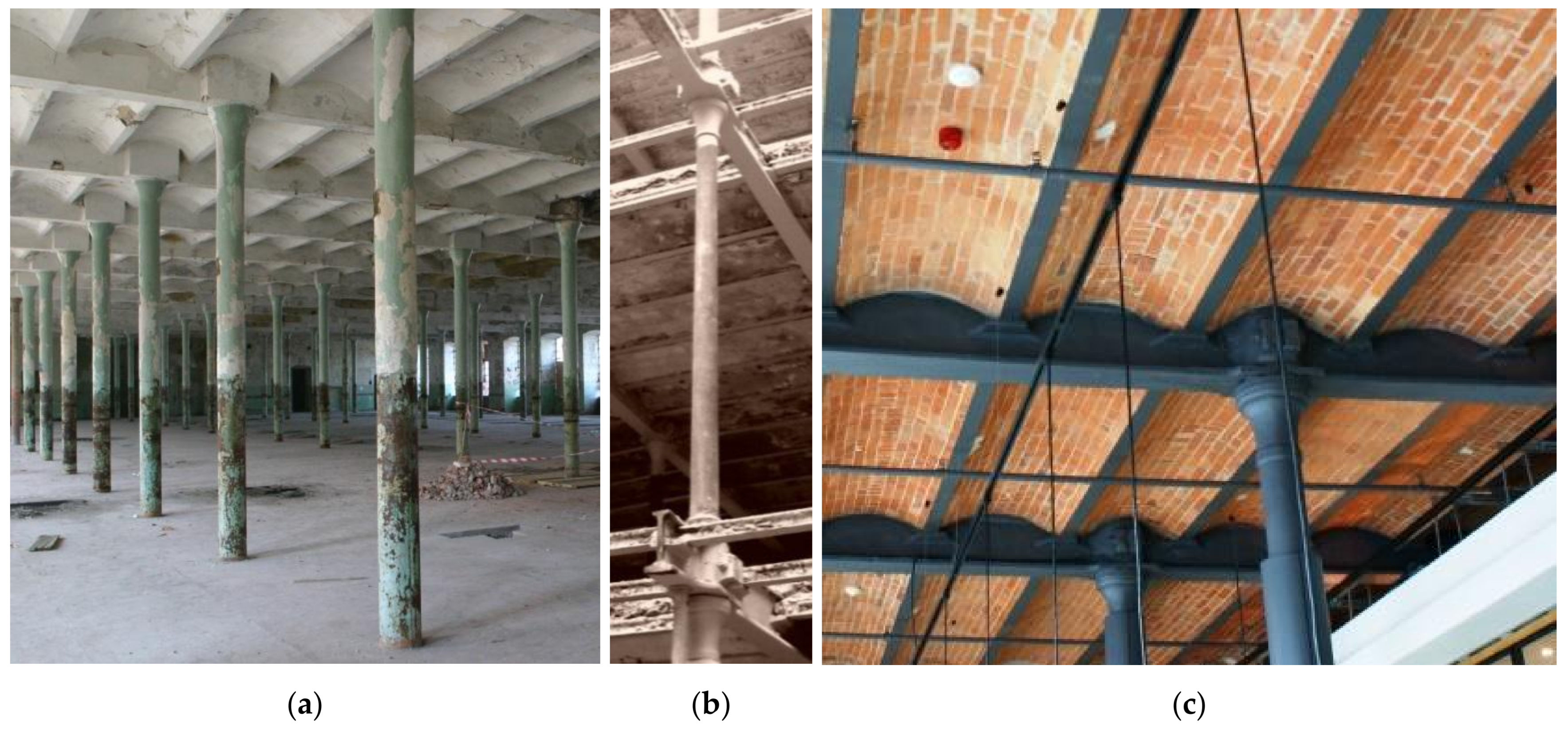
In the years 2002–2006 a large-scale revitalization project in the former Izrael Poznański’s industrial complex, in which the textile cotton factory operated, was implemented in Łódź. The reconstruction of existing buildings has been performed in a way to partially preserve the former atmosphere of this place. This was also in case of the former spinning mill, which was transformed into a hotel. The designers decided to leave the existing structural elements, visible in Figure 4. For this purpose, a detailed stocktaking of the existing cast-iron elements was made, including measurements in several places. In the case of selected columns, the thickness of the section walls was measured using an ultrasonic thickness gauge. Thickness was measured at approximately 100 locations on each of the columns. It was found that the outer column diameter ranged from 148.3 to 150.3 mm, while the inner diameter from 90.5 to 93.5 mm, indicating a non-prismatic cross-section of the columns (convergence of about 2.5%). The thickness of the walls varied between 23.5 mm and 33 mm along the column perimeter.
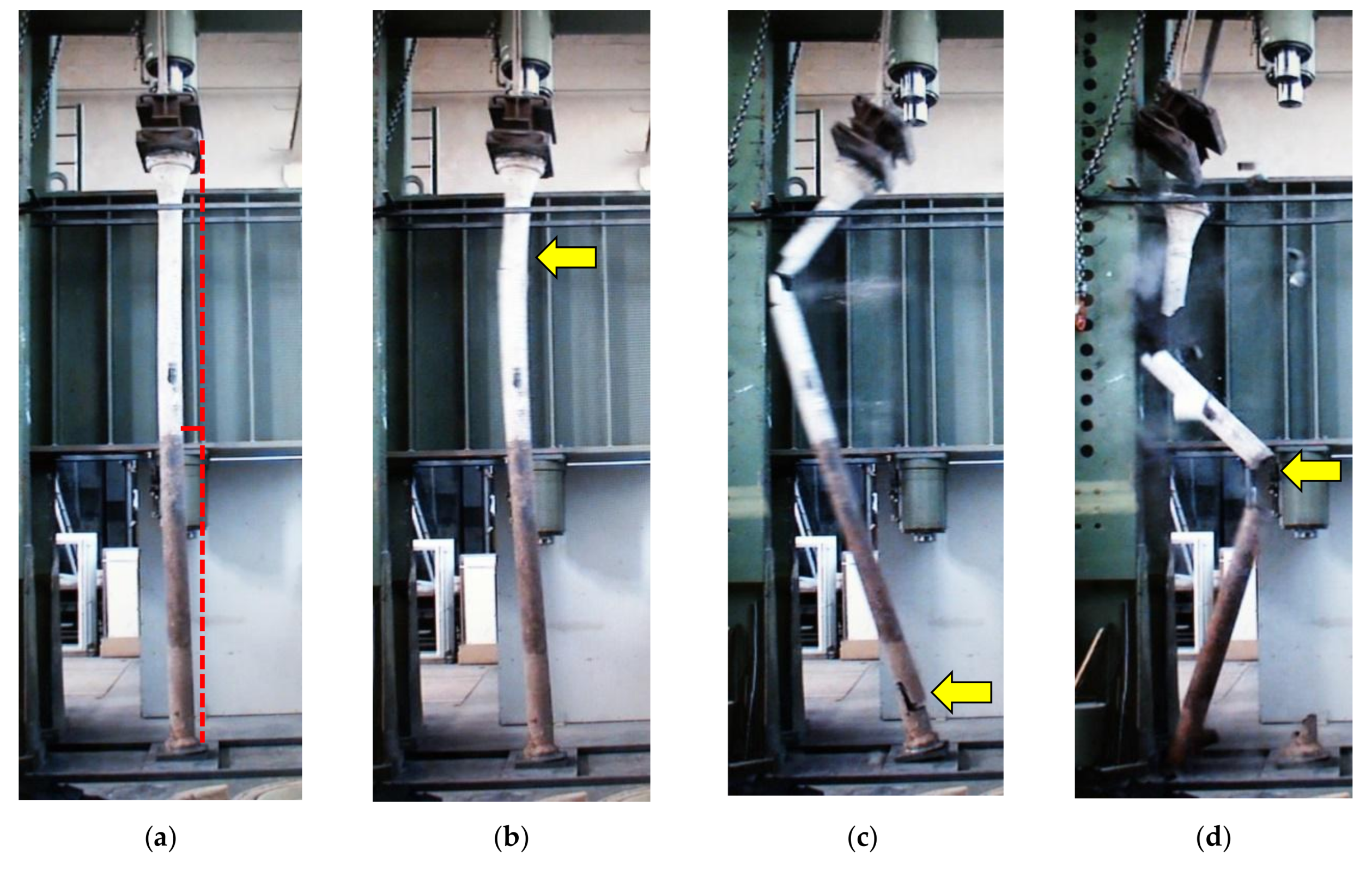
Due to uncertainty regarding the actual load-carrying capacity of cast-iron columns, it was decided to carry out destructive tests. For this purpose, four cast-iron columns from the demolished part of the building were used. The tests were carried out in the laboratory in Vienna [19]. Figure 5 shows the course of the final phase of the test of the selected column. Buckling of the column can be clearly seen. Then the fracture of the element was observed in ¾ of its height and close to the base. It is worth noting that the first crack did not occur in the mid-height, where the horizontal displacement was the highest. The reason can be found in the variable cross-section as well as the inhomogeneity of the cast-iron, which was confirmed by the subsequent inspections. In the cross sections where the failure was initiated, casting imperfections in the form of air bubbles were found. All of the failure phases, shown in Figure 5, occurred within a time interval of about 0.1 s.
The results of the tests on four columns demonstrated that the experimental load-carrying capacities were several times (13 ÷ 15) higher than the ultimate loads determined according to the DIN 1051 [16] procedure. The safety factor predicted at level 6 turned out to be more than twice as high.
3.2. Shopping and Entertainment Complex ”Monopolis” in Łódź
At present, the third of the large industrial complexes is being revitalized in Łódź. These are the facilities of the former Vodka Monopoly built in 1902. In these plants the production of quality spirits occurred almost continuously until the beginning of the 21st century. In 2013, as a result of ownership changes, a new era for one of the most valuable monuments in Łódź, currently known as “Monopolis”, began. In Figure 6 the main building of the complex during reconstruction is presented.
Due to the planned reconstruction, it was necessary to assess the load-carrying capacity of the existing structural elements. In particular, this concerned cast-iron columns, which were planned to be preserved. Due to the change in use, the load capacity of the columns had to be determined in order to allow a safe, and at the same time reasonable, estimation of the permissible ceiling load. For this purpose, a destructive test of the column, as well as accompanying tests of cast-iron features, were carried out at the Laboratory of Department of Concrete Structures at Lodz University of Technology. Based on the tests, the following strength properties of the cast-iron, used in the columns, were determined [20]:
- ultimate stress by axial compression: Rc = 450.6 MPa,
- ultimate stress by axial tension: Rt = 103.8 MPa.
It should be noted that these values were close to previous ones, obtained with tests of cast-iron taken from the girders [21]: Rc = 526 MPa and Rt = 128 MPa. This means that the Rc/Rt ratio ranged from ~4.1 to 4.3 and was characteristic for brittle materials; however it was slightly lower than 6, conventionally assumed for typical 19th century cast iron.
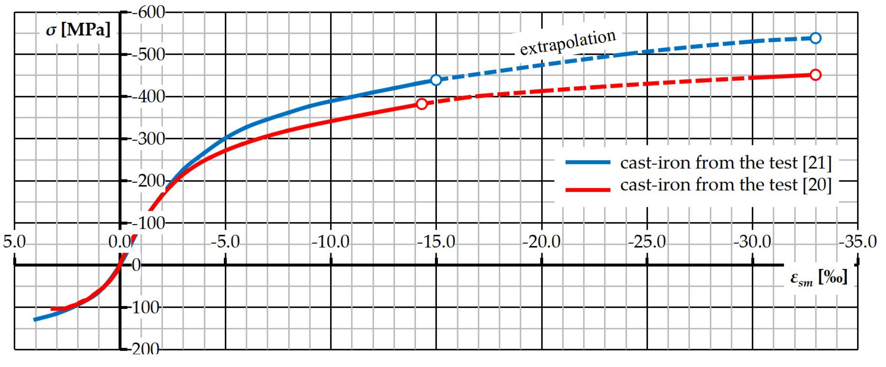
On the basis of the strain measurements secant modulus of elasticity of about 100 ÷ 115 GPa was also determined. Very high deformability of cast-iron turned out to be surprising—the ultimate shortening of the tested samples reached over 30‰, which can be seen in Figure 7.
The test of the column was carried out in the hydraulic press with a maximum pressure of 6000 kN. The specimen was loaded axially under load control. A test specimen with a length of l = 3100 mm was made from the column selected for destructive test. Before starting the test, the element was stocktaken by measuring the thickness of the section walls at the base and at the head at 6 points around the perimeter. Measurements were made using a calliper with an accuracy of 0.05 mm. During the test, longitudinal strains were measured in the mid-height of the column in three bases around its perimeter. Strains were measured with resistive strain gauges with an accuracy of ±0.5% and recorded using a data acquisition system. The results of the measurement were shown in Figure 8. In the initial phase of the test, uniform shortening of the column was recorded. At about 80% of the ultimate force, a gradual decrease in strains was observed in one of the measuring bases (T3). At the maximum load these strains were close to zero. Considering the results of the measurements registered just before the failure, the maximum strains in the cross-section equal to εt = 1.66‰ (on the tensioned side) and εc = −12.55‰ (on the compressed side), were estimated.
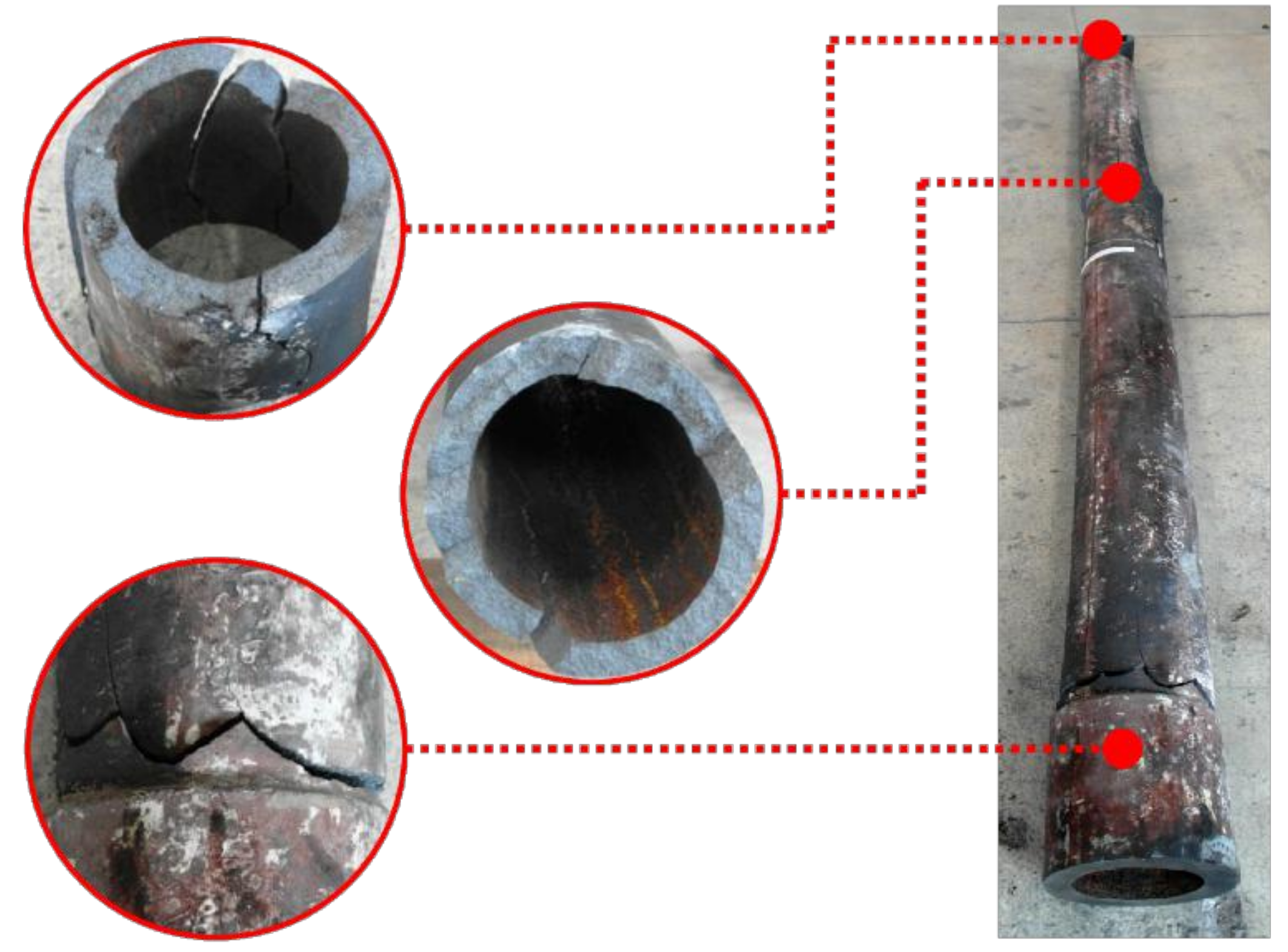
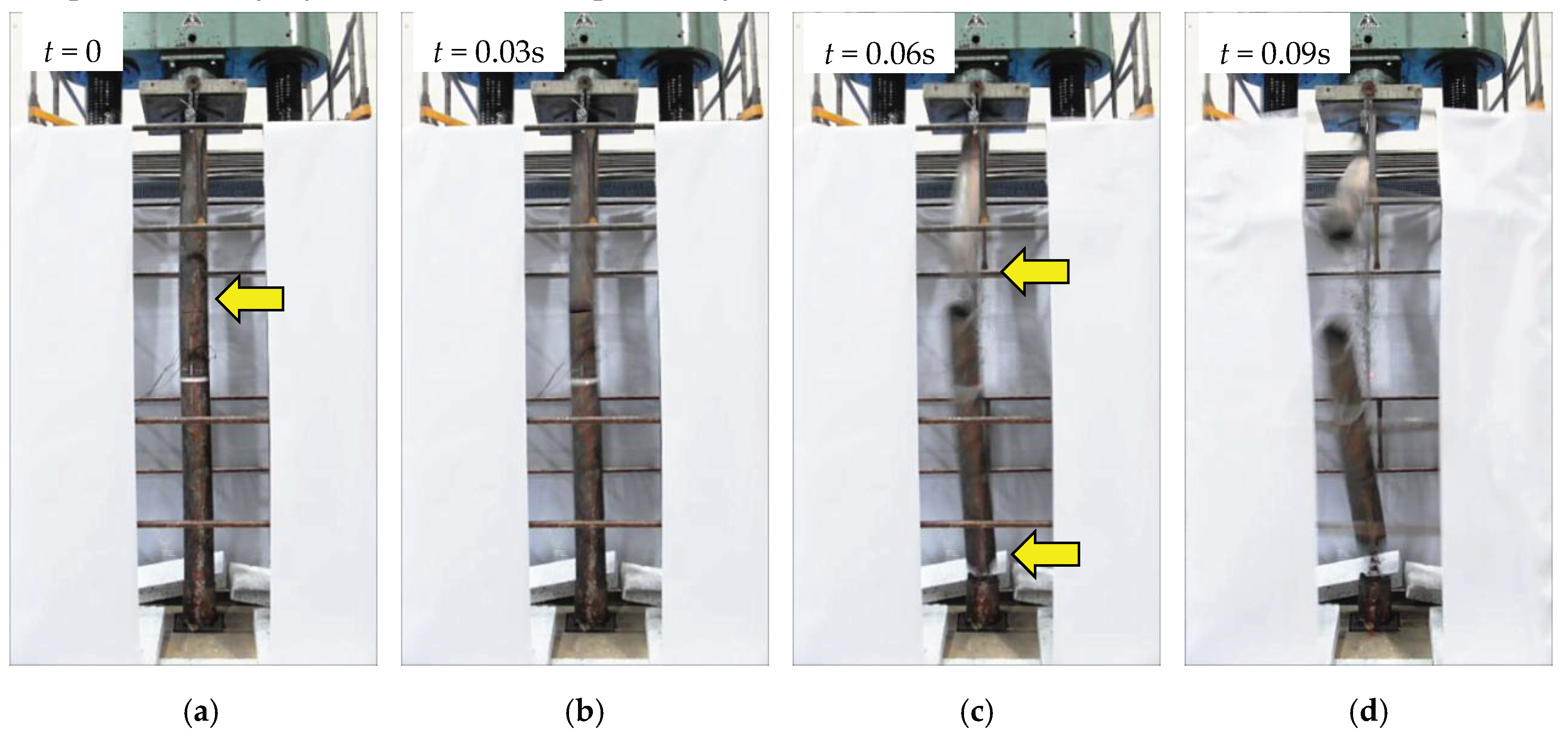
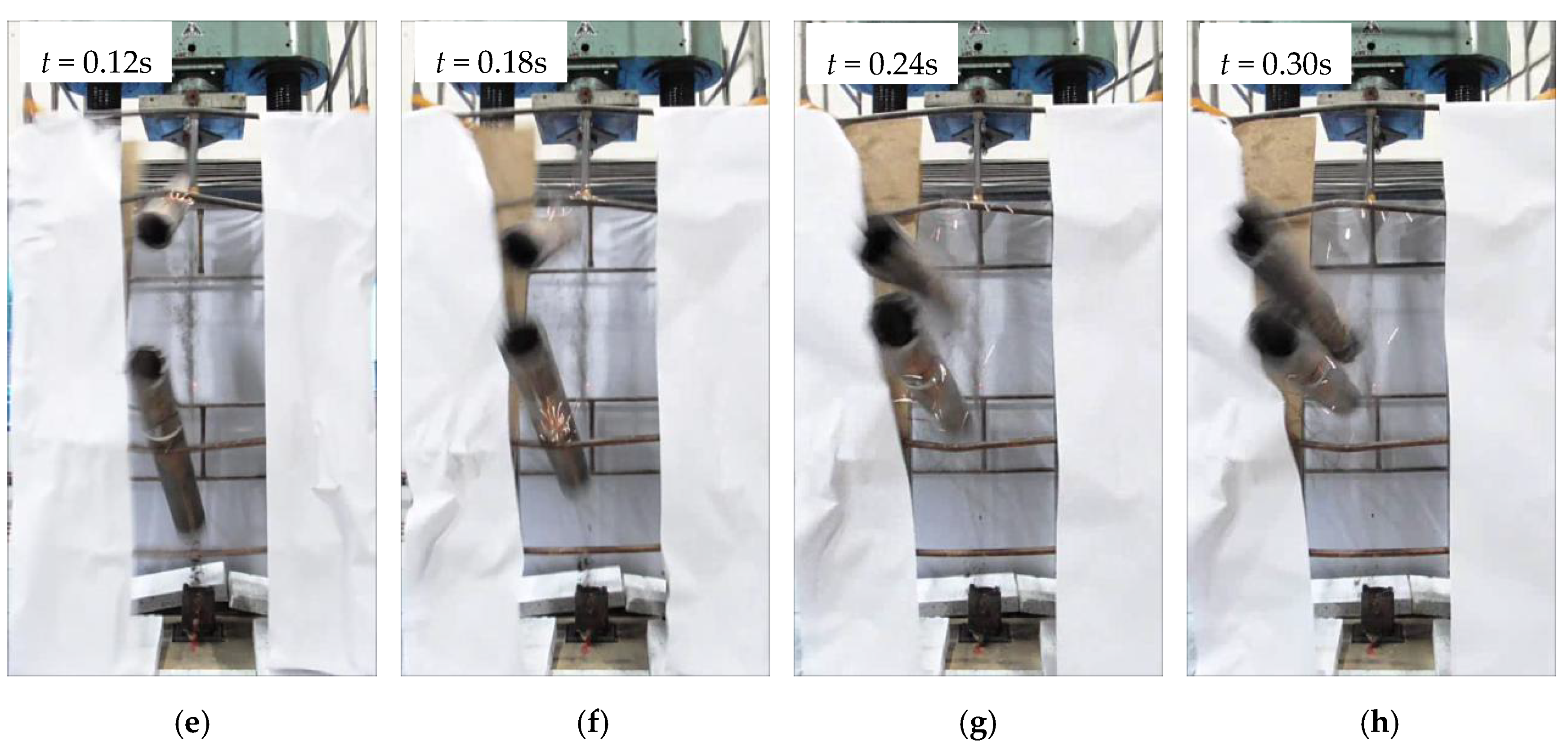
The failure of the column was extremely violent and occurred within fractions of a second at a load of about Fmax = 2605 kN. In the final phase of the test at the load of about 90% of the destructive force, gradual cambering of the column began to be observed, which allowed us to conclude that the failure was a consequence of the loss of stability (buckling). It was initiated by a crack in the upper part of the column, at 2/3 of its height. Immediately after the first crack occurred, the next one was observed in the vicinity of the column base. The column was broken into 3 parts, which were forcefully ejected from the test setup. In Figure 9, the tested column after failure was presented. Casting defects in the form of furnace slag inclusions and blow-holes were visible in all of the three sections where the failure was initiated.
In Figure 10 the course of the final phase of the test was demonstrated. The course of the failure was very similar to that observed during previous investigations [19]; compare with Figure 5. Sections, where failure was initiated, were marked with a yellow arrow. It is worth noting that the column failed within fractions of a second, and indication of the subsequent phases of destruction was possible only by means of time-lapse analysis.
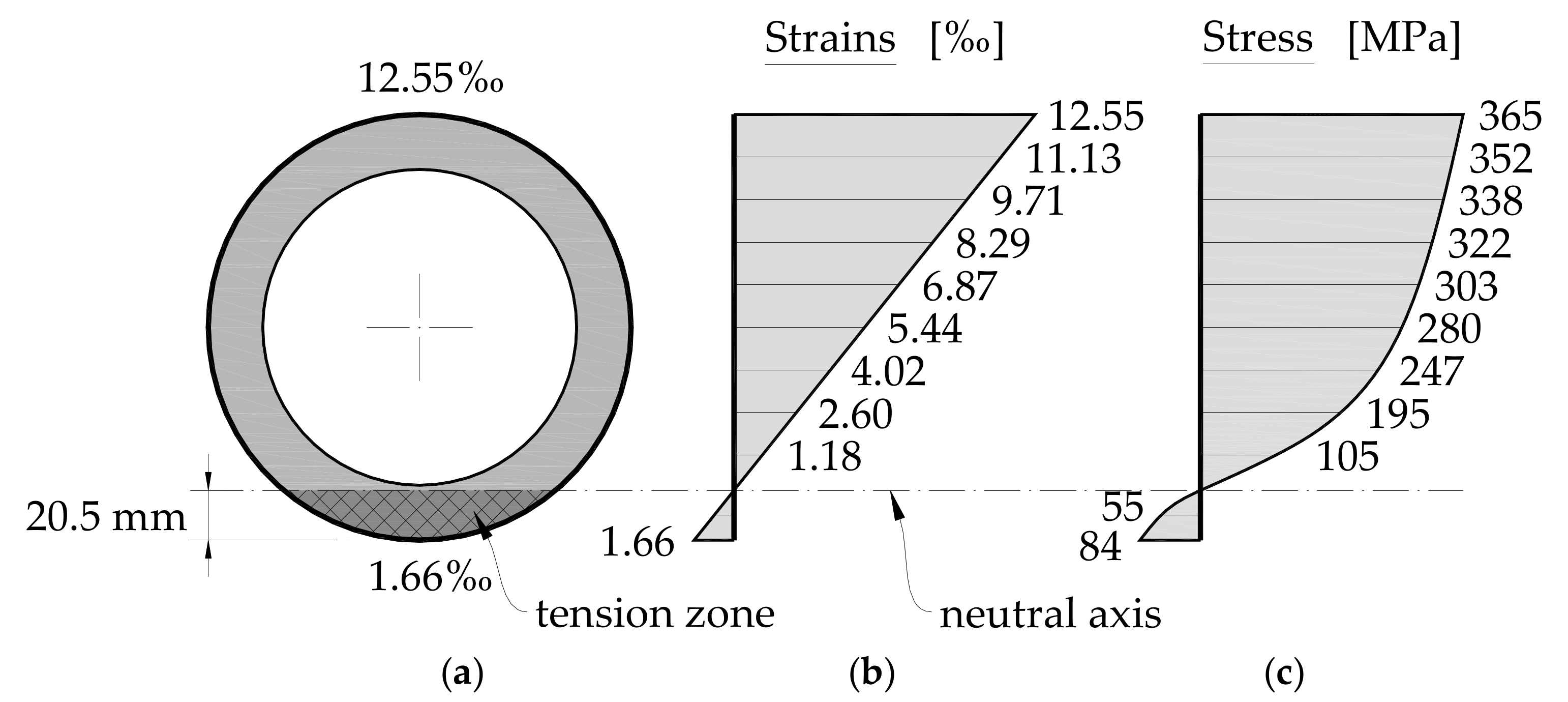
Assuming Euler–Bernoulli theory the strain distribution in the cross-section just before failure was plotted; see Figure 11. The recorded values indicated a transgression beyond the elastic range of the material. On the basis of the stress-strain relationship (see Figure 7), the stress in the cross-section were determined. The maximum stress was equal to 84 MPa (on the tensioned side) and 365 MPa (on the compressed side). These stresses accounted for 80.9% and 81.0% of the tensile and compressive strength of cast-iron, respectively. The maximum strains on the compressed side were significantly lower than the ultimate strain εcu = −33.0‰; therefore, it can be concluded that the failure of the column was the result of exhausting the material capacity on the tensioned side due to deformation associated with buckling.
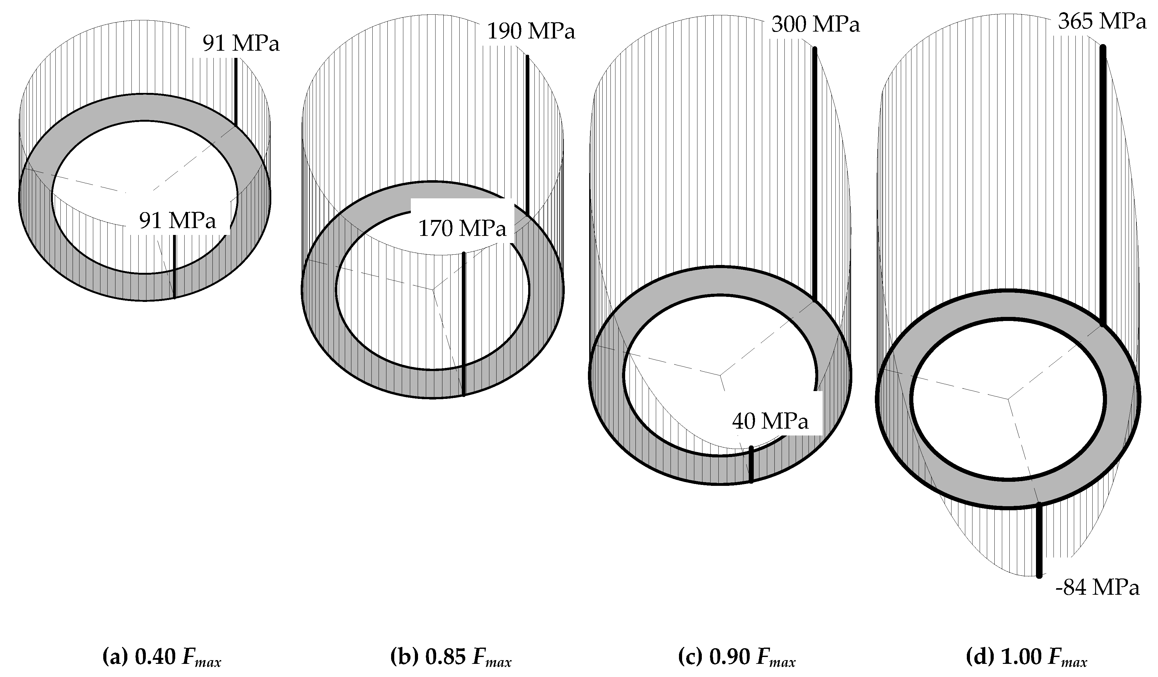
In Figure 12 the development of stress in the column cross-section in the subsequent stages of the test is presented. The stress was determined on the basis of the strain measurements and the nonlinear stress-strain relationship (see Figure 7, “−” denotes tensile stress). Up to about 80% of the ultimate force, the stresses in the cross-section were of a similar value and nature. By further increase in load, a decrease in stress, and then the change of its character into tensile, was observed. At the ultimate load Fmax, the maximum tensile stress was about 7.5 times lower than the maximum compressive stress in the cross-section.
Previous analyses carried out as part of the revitalization project of the I.Poznański factory complex demonstrated that the actual load capacity of the cast-iron columns can be several times higher than the theoretical one, resulting from the historical design procedures. For this reason it was decided to perform comparative calculations also for the considered column. The cross-section of 2/3 of the column height was adopted for the analysis, because the failure was initiated at that point; see Figure 13. Based on the measurements, the necessary geometric and strength characteristics were determined:
- cross-sectional area: A = 10,526 mm2,
- lowest moment of inertia: J2 = 29,995,276 mm4.
Taking into account the length of the tested column (l = 3100 mm) and the adopted static scheme (Eulerian pin-ended bar), the slenderness of the element was calculated as:
Then, using the expressions (1), (2), (4), (6), the permissible stresses and the corresponding load-carrying capacity of the element were determined:
- according to the Schwarz-Rankine formula (1):
- according to the Tetmajer equation (2):
- according to DIN 1051 (4):
Comparing the loads obtained in the light of the test result, it can be concluded that the 20th century design procedures turned out to be very conservative. The calculated design loads were therefore 4.4 ÷ 9.3 times lower than the experimental one. This illustrates how cautiously the engineers of that time approached the design of cast-iron columns, what was associated with a high uncertainty regarding the material properties related to the imperfection of the production process. The application of more modern design principles allowed for a much more accurate estimation of the load-carrying capacity. In the case of calculations according to the formula (6), the theoretical load was lower by only about 14% compared to the value determined experimentally.
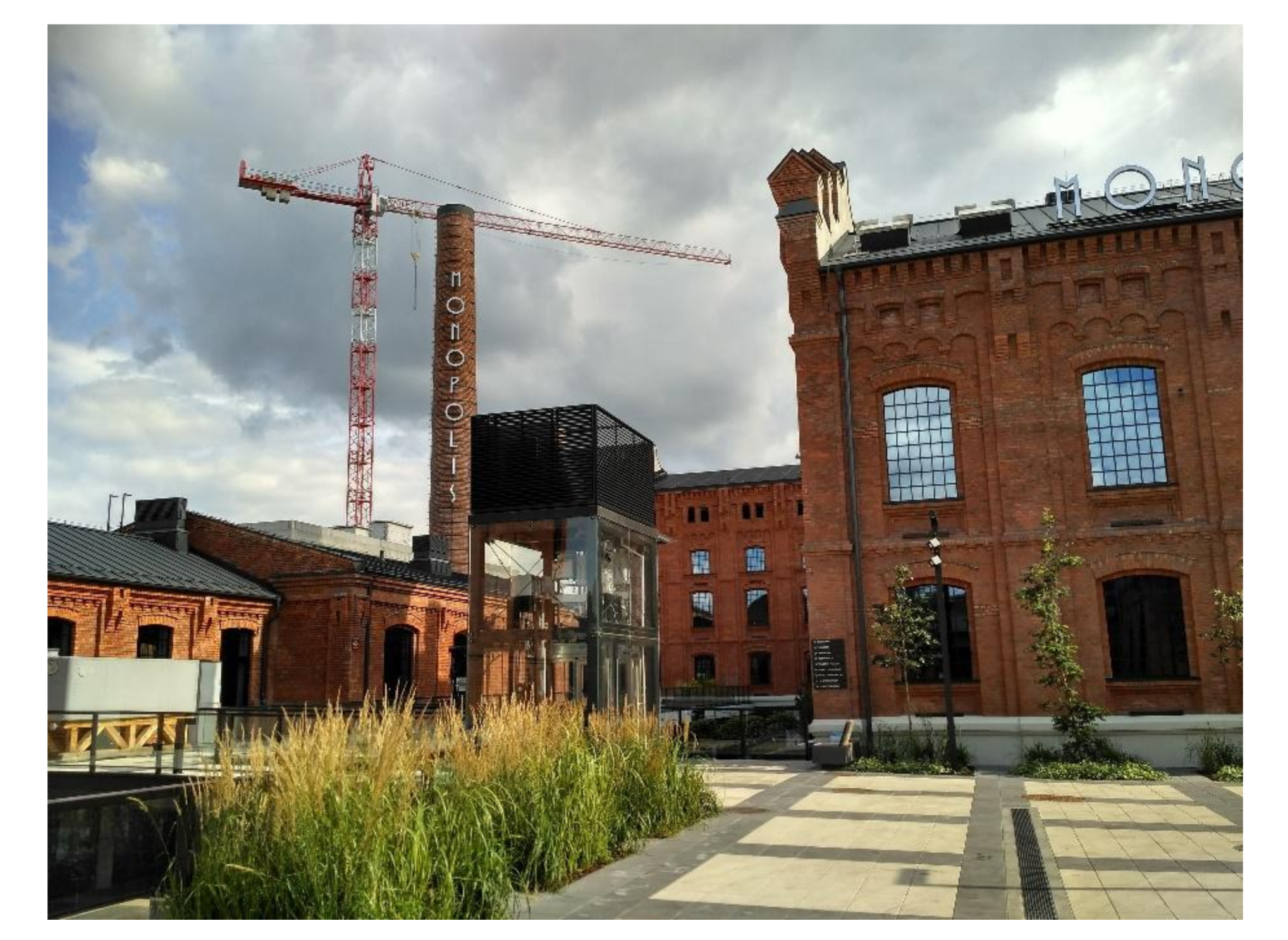
The experimental investigations conducted proved that the existing cast-iron columns in the post-factory building were characterized by sufficient load-carrying capacity, allowing for adaptation to new purposes. Currently, the revitalized buildings of the former factory complex of Vodka Monopoly house offices and service premises of the “Monopolis” complex, operating since 2019. Figure 14 shows some of the revitalized post-industrial buildings.
4. The Examples of Cast-Iron Column Failures
4.1. Housing Estate at Tylna st. in Łódź
One of the examples of cast-iron column failure took place in the building included in the revitalized complex of the former S. Barciński wool factory in Łódź. The construction of the complex began in 1884. Initially, a wool products factory was built, while two years later a spinning mill, a weaving mill, and a finishing plant for woolen and semi-woolen products were built.
In the building of the former wool products factory, wooden ceilings were supported by external masonry walls and internal cast-iron columns. Due to the technical condition of the ceilings, it was decided to replace them with monolithic reinforced concrete ribbed slab, maintaining the original shape of the ceiling; see Figure 15. As a result of the change in the original use of the building from industrial to residential, the live load decreased, so the increase of permanent loads, resulting mainly from the self-weight of the reinforced concrete slabs, did not significantly affect the total load.
During the construction works that were carried out in winter, vertical cracks in the ground-floor columns were found. The width of these cracks was significant and in some cases reached a few millimeters; see Figure 16. Based on the inspections performed, it was found that their source was a frozen mixture of water, oil, and cement paste trapped inside the columns cross-section. The oil was a remnant from the period of the facility’s operation as a spinning mill, while the water got inside the columns probably during the execution of concrete works. The tight cast-iron coat prevented the evaporation of water, which resulted in bursting of columns at temperatures of −20 °C, which were noted in the winter of 2013.
The initial method of repair proved to be ineffective. The contractor for the reconstruction works tried to solve the problem on his own by welding the cracks. However, new cracks appeared soon in the vicinity of the weld joints, because water was not removed from the inside. As an alternative method of repair, steel rings along the cracks were proposed. An independent expert proposed the solution shown in Figure 17. It consisted of placing steel rings in the places where the cracks appeared [22]. The rings consisted of two halves joined by a single V-weld. In order to ensure the correct fit of the clamps to the column during the execution of the weld-joints, special pressure clamps with an elastic washer were used. The clamps were dismantled after the completion of welding. The number of rings was selected individually for each column, depending on the length of the crack.
4.2. Rail Overpasses in Wrocław
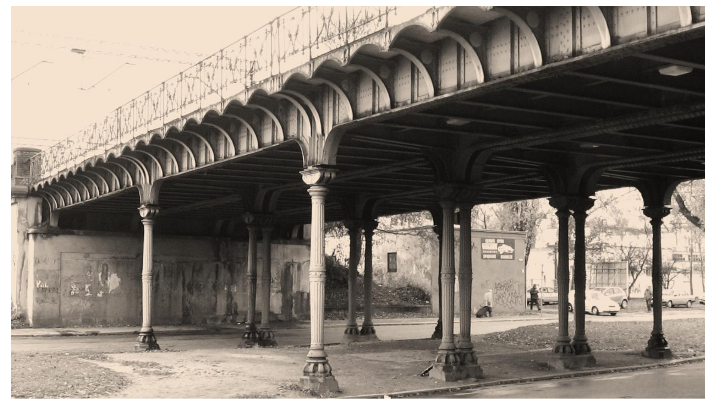
Another spectacular example of a serious failure of cast-iron columns took place at the end of 2009 in Wrocław. As part of the works related to the modernization of the railway line, it was necessary to strengthen the supports of existing overpasses—pinned-pinned columns, so called Hartung’s columns (Hartungsche Säule); see Figure 18. The project provided for increasing the load-carrying capacity of the cast-iron columns by filling them with a coarse-grained concrete mix. It was not an innovative solution. This method of strengthening was previously used successfully in Germany for over 300 columns [23]. The effectiveness of this method has also been proved by research conducted at the Berlin University of Technology [9]. Filling of cast-iron section with concrete enabled to increase the load-carrying capacity from 16% to 19%, with simultaneous reduction of deformations by 15 ÷ 35%.
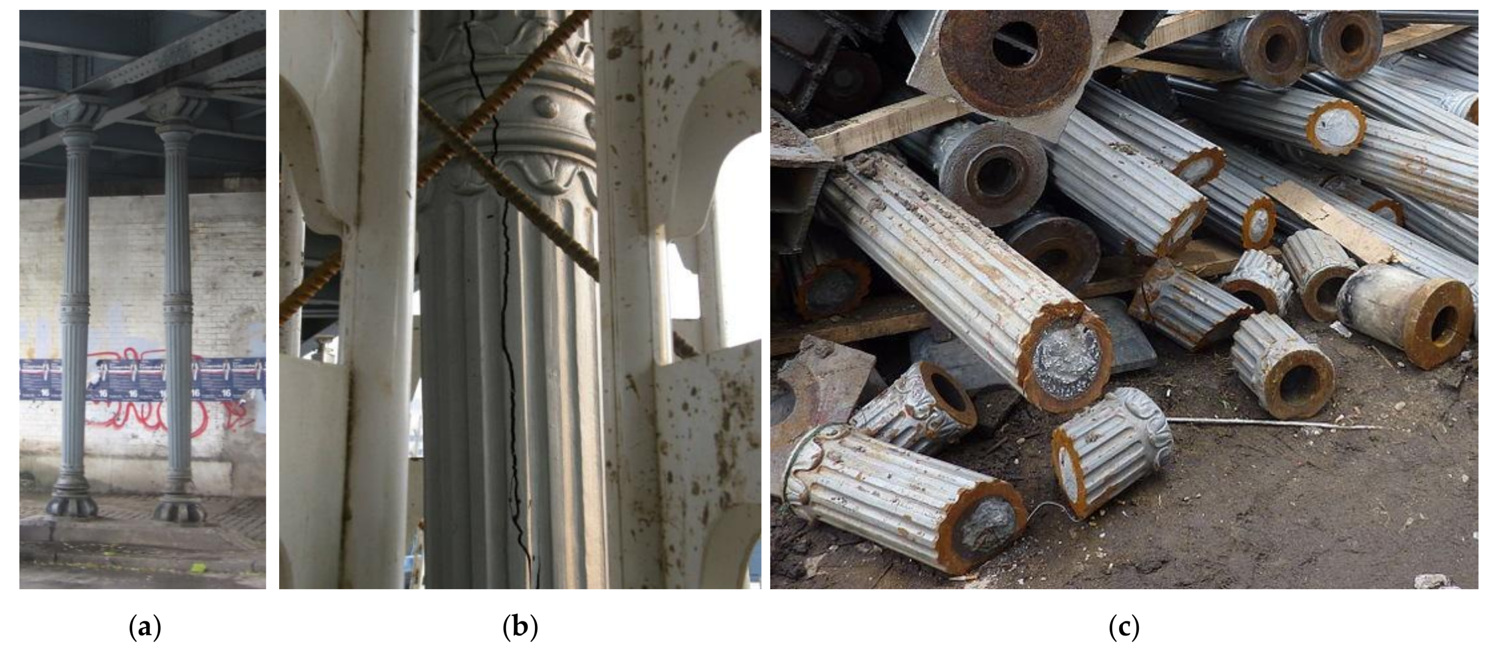
The attempt to strengthen the columns in Wrocław, however, ended in failure. During the construction works carried out in December, the appearance of vertical cracks was found in several columns. The analysis of the causes of failure [23] showed that it was most likely the consequence of unconsidered changes in the original design. It assumed the use of a concrete mix with coarse aggregate, while any voids and cavities were planned to be filled with epoxy resin. Finally, a fine-grained mix (mortar) was used, with polyurethane resin as a filler, which required a lot of water for wetting the substrate, has been applied. Due to significant temperature drop during construction works, the water trapped inside the section froze and, as a result of the increase in volume, led to bursting of the columns; see Figure 19. Due to the risk of a structural failure, it was decided to immediately exclude the overpasses from use, which was associated with significant impediments in railway traffic.
Different methods of repair were considered, including strengthening the columns with carbon fiber mats and fabrics in the form of external coating (the effectiveness of such types of reinforcement was demonstrated, among others, in [11]). Finally, however, the contractor decided to replace all of the columns with the new ones, this time steel columns with a shape reminiscent of the original one. This decision was also dictated by the concern about the efficiency of filling the columns with concrete. As shown in the subsequent inspection, in many cases the defects in filling the columns reached even 1/3 of their height, which significantly limited the effectiveness of the designed strengthening method.
5. Conclusions
Previous experiences with cast-iron columns have shown that they can still be successfully used as structural elements in revitalized buildings for which a change of purpose is planned. However, due to the method of manufacturing cast-iron elements, they are characterized by material and geometrical imperfections, which are very often difficult to estimate. Also considering the properties of cast-iron (high brittleness), affecting the failure mode of column, which is violent and non-signalized, it should not be surprising the conservatism of the former engineers, who designed elements made of cast-iron. For this reason, application of 20th century design rules may lead to a very conservative estimation of the load-carrying capacity of existing columns, as demonstrated by the experimental studies conducted in Łódź and Vienna.
The previous experiences with cast iron-columns allow us to state that in many cases they can successfully be preserved as the main structural elements, provided that they do not show any visible damage. If the change in the use of the building forces an increase in loads, then it is necessary to analyze the load-carrying capacity of the columns in more detail. In the first step, the design principles that were in force in the 19th and 20th, thus at the time when the building was erected, can be applied. The design equations have a simple formula and, as has been shown, allow for a very conservative estimation of the load-carrying capacity of cast-iron columns. If the load capacity estimated in such way turns out to be insufficient, then it may be justified to use more recent design rules [5], taking into account the non-linear characteristics of cast iron. Destructive tests performed on elements taken from the structure can also be invaluable help, because they allow for determination of the actual bearing capacity, which, as shown, may even be several times higher than the theoretical one.
The examples of failures of cast-iron columns in modernized buildings and structures demonstrated that all works related to the rehabilitation of existing cast-iron columns should be preceded by a detailed analysis, carried out not only in terms of structural analysis, but also including all of the aspects of construction technology. As previous experience has shown, repair of cast-iron elements is not an easy issue. Welding of cast iron is not recommended because the presence of graphite inclusions interferes with creation of a weld bead. The thermal stresses that arise in the vicinity of the weld are also important. This can lead to the material fracture later, as was the case with the columns in the post-factory building discussed earlier. Very important information can also be provided by the study of the microstructure of the material, which will allow the form of graphite particles to be determined. The presence of graphite in the form of flakes will indicate a high brittleness of the material, which in some cases may preclude preserving the existing elements.
Wherever the structure should be more ductile, it may be justified to consider filling the columns with concrete. The composite structure created in this way is characterized by a higher load-carrying capacity, as well as deformability, as shown the tests [10]. The use of CFRP composite materials can be an effective way to increase the load capacity of columns [11], but due to the linear-elastic characteristics of the composite, it does not allow the failure mode to be changed to a more ductile (signalized) one.
Author Contributions
Conceptualization, M.G., T.U.; methodology, M.G., T.U.; formal analysis, M.G., T.U.; investigation, M.G., T.U.; resources, M.G., T.U.; writing—original draft preparation, M.G., T.U.; writing—review and editing, M.G.; supervision, T.U. All authors have read and agreed to the published version of the manuscript.
Funding
This research received no external funding.
Conflicts of Interest
The authors declare no conflict of interest.
References
- Gołdyn, M.; Urban, T. Failures of the Cast-Iron Columns of Historic Buildings—Case Studies. In Proceedings of the 8th Euro-American Congress REHABEND, Granada, Spain, 24–27 March 2020. [Google Scholar]
- Czapliński, K. Dawne Wyroby ze Stopów Żelaza (Historical Elements from Iron Alloys), 1st ed.; Dolnośląskie Wydawnictwo Edukacyjne: Wrocław, Poland, 2009; p. 100. [Google Scholar]
- Hodgkinson, E. Experimental Researches on the Strength of Pillars of Cast Iron and other Materials, 1st ed.; Philosophical Transactions of the Royal Society Part 2; Royal Society: London, UK, 1840; p. 385. [Google Scholar]
- Tetmajer, L. Die Angewandte Elastizitäts- und Festigkeitslehre (The Applied Elasticity and Strength Theory), 1st ed.; Franz Deuticke: Leipzig und Wien, Austria, 1905. [Google Scholar]
- Rondal, J.; Rasmusen, K.J.R. On the strength of cast iron columns. J. Constr. Steel Res. 2014, 60, 1257–1270. [Google Scholar] [CrossRef]
- Brych, I.; Holický, M.; Jung, K.; Sýkora, M. Uncertainty in resistance models for historic cast-iron columns. WIT Trans. Ecol. Environ. 2015, 194, 473–482. [Google Scholar] [CrossRef] [Green Version]
- Friedman, D. Preservation Engineering. Struct. Mag. 2005, 9, 10–12. [Google Scholar]
- Friedman, D. Cast-iron-column strength in renovation design. J. Constr. Facil. 1995, 9, 220–230. [Google Scholar] [CrossRef]
- Heyde, S. Nachweisverfahren für Historische Stützen aus Grauguss (Design Procedure for Historical Cast-Iron Columns). Ph.D. Thesis, Technische Universität Berlin, Berlin, Germany, 2008. [Google Scholar]
- Heyde, S.; Geißler, K. Strength of Concrete Filled Historic Cast-Iron Columns. In Proceedings of the International Conference on Composite Construction in Steel and Concrete, Devil’s Thumb Ranch, Tabernash, CO, USA, 20–24 July 2008. [Google Scholar]
- Marcinowski, J.; Różycki, Z. Reinforcement of Existing Cast-Iron Structural Elements by Means of Fiber Reinforced Composites. Civil Environ. Eng. Rep. (CEER) 2016, 20, 37–45. [Google Scholar] [CrossRef] [Green Version]
- Salmon, E.H. Columns; Hazell, Watson & Viney: London, UK, 1921. [Google Scholar]
- Rondal, J.; Rasmussen, K.J.R. On the Strength of Cast Iron Columns; Research Report No R829; The University of Sydney Department of Civil Engineering: Sydney, NSW, Australia, 2003; p. 25. [Google Scholar]
- Marcinowski, J.; Różycki, Z. Oszacowanie nośności wyboczeniowej słupów żeliwnych w rewitalizo-wanych obiektach historycznych (Estimation of the buckling capacity of cast-iron columns in the revitalized historic buildings). In Proceedings of the 56th Scientific Conference of the Committee of Civil Engineering of Polish Academy of Science and Committee of Science of the Polish Association of Civil Engineers and Technicians, Kielce—Krynica, Poland, 19–24 September 2010; pp. 683–690. [Google Scholar]
- Österreich-Ungarischer Bauratgeber-Bauindustrielles Handbuch (Austro-Hungarian Building and Industrial Handbook), 2nd ed.; Verlag von Moritz Perles: Wien, Austria, 1914.
- DIN 1051. Berechnungsgrundlagen für Gusseisen im Hochbau (Design Principles for Cast-Iron Structural Elements in Buildings); Deutsches Institut für Normung: Berlin, Germany, 1937. [Google Scholar]
- Niezgodziński, M.E.; Niezgodziński, T. Wzory, Wykresy i Tablice Wytrzymałościowe (Equations, Charts and Design Tables), 4th ed.; PWN: Warszawa, Poland, 1984. [Google Scholar]
- PN-90-B-03200 Konstrukcje stalowe. Obliczenia Statyczne i Projektowanie (Steel Strucutres. Static Calculations nad Design); Polski Komitet Normalizacyjny: Warszawa, Poland, 1990. [Google Scholar]
- Untersuchungsbericht über Gusssäulen MA39—VFA 2007-1038.01 (Test Report on Cast-Iron Columns); Magistrat der Stadt Wien Magistratsabteilung 39 Prüf-, Überwachungs- und Zertifizierungsstelle der Stadt Wien VFA—Labors für Bautechnik: Vienna, Austria, August 2007.
- Urban, T.; Gołdyn, M. Raport z Badania Słupa Żeliwnego (Report from the Test of Cast-Iron Column); Department of Concrete Structures, Lodz Univeristy of Technology: Łódź, Poland, 2018. [Google Scholar]
- Czkwianianc, A.; Bodzak, P.; Kozicki, J.; Urban, T. Badania niszczące żeliwnych dźwigarów stropowych dawnej przędzalni w Manufakturze w Łodzi (Destructive tests on cast-iron girders of the former spinning mill in Manufaktura in Łódź). Zesz. Nauk. Politech. Łódzkiej 2008, 57, 22–37. [Google Scholar]
- Kozicki, J.; Ryniecki, M. Projekt Wzmocnienia Słupów Żeliwnych w Budynku F (Detailed Design of the Strengthening of Cast-Iron Columns in Building F); Biuro Projektowe dr inż. Jan Kozicki, Łódź, Marzec: Łódź, Poland, 2012. [Google Scholar]
- Czapliński, K.; Gawron, K. O żeliwnych elementach konstrukcyjnych i dekoracyjnych (About cast-iron strucutual and decorative elements). Przegląd Bud. 2011, 4, 56–59. [Google Scholar]
Figure 1.
Example of the imperfections in the structure of cast-iron.

Figure 2.
Cross-sections at different locations on the column length.

Figure 3.
Overall instability coefficient φ as a function of column slenderness λ.

Figure 4.
Structure of the former I. Poznański’s spinning mill: (a) before, (b) during, and (c) after reconstruction.
Figure 4.
Structure of the former I. Poznański’s spinning mill: (a) before, (b) during, and (c) after reconstruction.

Figure 5.
Course of the final stage of the test [19]: (a) buckling of the column, (b) occurrence of the first crack, (c) occurrence of the second crack at the column base, (d) facture at the mid-height (with the red line primary axis of the column has been marked, while the yellow arrows indicate the locations of the cracks).

Figure 6.
Main building of the former Vodka Monopoly in Łódź during construction works.

Figure 7.
Stress-strain relationship characterizing cast-iron from structural elements.

Figure 8.
The results of measurements at the mid-height of the column (the colors correspond to the measuring points presented in the cross section).
Figure 8.
The results of measurements at the mid-height of the column (the colors correspond to the measuring points presented in the cross section).

Figure 9.
View of the column after end of the test (the column composed of parts).

Figure 10.
Course of the final stage of the test: (a) 0, (b) 0.03 s, (c) 0.06 s, (d) 0.09 s, (e) 0.12 s, (f) 0.18 s, (g) 0.24 s, (h) 0.30 s. after occurrence of the first crack (with yellow arrows locations of the subsequent cracks have been marked).
Figure 10.
Course of the final stage of the test: (a) 0, (b) 0.03 s, (c) 0.06 s, (d) 0.09 s, (e) 0.12 s, (f) 0.18 s, (g) 0.24 s, (h) 0.30 s. after occurrence of the first crack (with yellow arrows locations of the subsequent cracks have been marked).


Figure 11.
Strains and corresponding stress in the column cross-section: (a) location of the neutral axis, (b) strain distribution, (c) stress distribution.
Figure 11.
Strains and corresponding stress in the column cross-section: (a) location of the neutral axis, (b) strain distribution, (c) stress distribution.

Figure 12.
Stress distribution corresponding to the subsequent load levels: (a) at 40%, (b) at 85%, (c) at 90% of the experimental load Fmax, (d) at failure.
Figure 12.
Stress distribution corresponding to the subsequent load levels: (a) at 40%, (b) at 85%, (c) at 90% of the experimental load Fmax, (d) at failure.

Figure 13.
Column cross-section at the point of failure initiation and the layout of the main central axes of inertia.
Figure 13.
Column cross-section at the point of failure initiation and the layout of the main central axes of inertia.

Figure 14.
View of the inner courtyard of the “Monopolis” office and entertainment complex.

Figure 15.
View of the ceilings in the factory building: (a) before the commencement of works, (b) during reconstruction.
Figure 15.
View of the ceilings in the factory building: (a) before the commencement of works, (b) during reconstruction.

Figure 16.
View of the damaged cast-iron columns (visible cracks of a width of few millimeters): (a) room no. 1, (b) room no. 2, (c) detail of the crack.
Figure 16.
View of the damaged cast-iron columns (visible cracks of a width of few millimeters): (a) room no. 1, (b) room no. 2, (c) detail of the crack.

Figure 17.
Detail of the strengthening of the broken cast-iron columns according to the idea of dr inż. J. Kozicki [22].
Figure 17.
Detail of the strengthening of the broken cast-iron columns according to the idea of dr inż. J. Kozicki [22].

Figure 18.
View of the rail overpass over Zaporoska Street in Wrocław.

Figure 19.
Hartung’s columns supporting the railway overpass at Stysia st. in Wrocław: (a) original elements, (b) view of the damaged column, (c) disassembled columns in the landfill.
Figure 19.
Hartung’s columns supporting the railway overpass at Stysia st. in Wrocław: (a) original elements, (b) view of the damaged column, (c) disassembled columns in the landfill.

© 2020 by the authors. Licensee MDPI, Basel, Switzerland. This article is an open access article distributed under the terms and conditions of the Creative Commons Attribution (CC BY) license (http://creativecommons.org/licenses/by/4.0/).
Share and Cite
MDPI and ACS Style
Gołdyn, M.; Urban, T. Failures of the Cast-Iron Columns of Historic Buildings—Case Studies. Infrastructures 2020, 5, 71. https://0-doi-org.brum.beds.ac.uk/10.3390/infrastructures5090071
AMA Style
Gołdyn M, Urban T. Failures of the Cast-Iron Columns of Historic Buildings—Case Studies. Infrastructures. 2020; 5(9):71. https://0-doi-org.brum.beds.ac.uk/10.3390/infrastructures5090071
Chicago/Turabian StyleGołdyn, Michał, and Tadeusz Urban. 2020. "Failures of the Cast-Iron Columns of Historic Buildings—Case Studies" Infrastructures 5, no. 9: 71. https://0-doi-org.brum.beds.ac.uk/10.3390/infrastructures5090071