1. Introduction
The latest research has shown that the interaction between soil and structure is a critical factor in the analysis of structures. Today we are moving away from considering a fixed base in earthquake engineering, as this method can cause great damage during an earthquake.
Computer and analytical approaches to solving soil–structure interaction problems have established the importance of SSI (soil–structure interaction) during dynamic loads. Since 1990, much effort has been made to understand the effects of soil on the structure during dynamic loading to improve the seismic design performance.
In 2017, an analysis on the impact of boundary conditions on the maximum displacement of the structure was carried out [
1]. Values that more than doubled were found as the difference between the maximum displacements, taking into account the SSI and a fixed base. In 2015, an analysis of the impact of the maximum displacement was carried out [
2], which led to more than 100% difference by increasing the height of the floors.
The soil–structure interaction has many effects on the structure, proved by a large amount of research that shows that SSI negatively influences the structure, and in other cases, the SSI can favorably affect the structure [
3]. Moreover, an unsafe design can lead to the failure of the whole structure as shown by past earthquakes (e.g., the Kobe earthquake in 1995) [
4].
It has been shown that the shear at the base of the flexible base is lower than the fixed base, while the inter-story drift of the structure increases significantly with the SSI effect [
5]. The effect of SSI can increase efforts because of the second-order effects which are not taken into account in the structural design. Moreover, in the literature, a major part of the research is focusing on the analysis of the maximum displacement and the inter-story drift, and the second-order effort is practically neglected.
In a numerical analysis developed by Shehu et al. in 2019, with design parameters, the design moments due to P-delta effects vary from about 25 to 100%, which is very significant of the resistance capacity of the elements [
6]. P-delta effects have only a small influence on the response. For buildings responding in a highly inelastic manner, P-delta effects can have a significant influence on response [
7].
In the structural analysis of structures, displacements and strains are assumed to be small. This means that the geometrical characteristics of the structure do not change during loading, known as the first-order effect; however, it is accepted that large displacements and strains will occur when buildings are under large earthquake loadings, also due to the effect of unfavorable soil–structure interactions. Therefore, the inter-story drift may be large and the second-order effects will produce additional forces and moments in the structure. These second-order effects can reduce structural stiffness [
7].
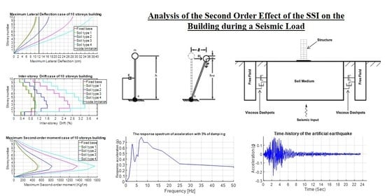
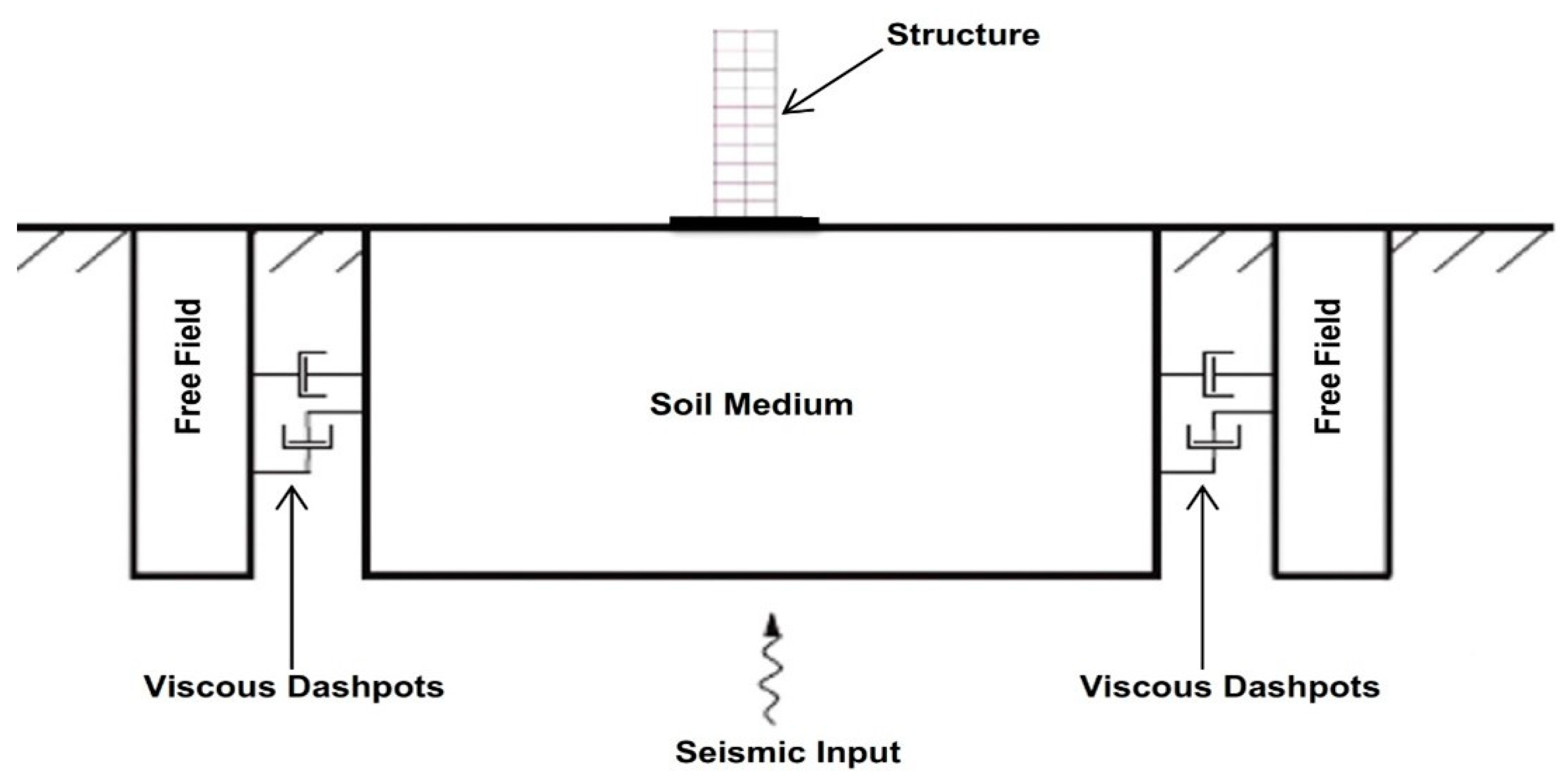
In this paper, an analysis of the impact of SSI was conducted to see the impact of the interaction of the soil structure, by changing the number of floors to 5, 8 and 10 floors and using four soil types, a fixed base and an acceleration spectrum with a maximum value of 0.24 g. For this purpose, several numerical models were used in the finite element calculation program FLAC 2D. In order to consider the dynamic soil–structure interactions in such a precise way, using the infinite elements of the soil to avoid the reflection of seismic waves, the results showed that the effects of the SSI generate values of moments due to P-delta effects that cannot be neglected.
2. Numerical Modeling
2.1. Model Description
In order to show the influence of the soil–structure interaction, a coupled model was created between structure, soil and infinite elements as shown in
Figure 1. The soil was surrounded by the free field boundary on FLAD 2D 2005. The frame structural elements were idealized as 2D elastic beam elements for BEAM and COLUMN. The behavior of the reinforced concrete RC frame structure was assumed to be elastic and was modeled by using the parameters in the next section. For the meshing, a coarse mesh was used [
8].
In numerical studies performed by different authors (e.g., [
9,
10,
11,
12]), concerning the 2D versus 3D modeling of the SSI, the difference between the results for the 2D and 3D models were negligible where the artificial model was adopted for rigid soil [
12]. A large amount of other research [
13,
14,
15,
16,
17] has applied a similar analysis.
In this research, we used three structural models, composed of 5-, 8- and 10-story models, and four selected soil types including one non-cohesive soil and three cohesive soils, represented as types 1, 2, 3 and 4.
In order to avoid the reflection of the seismic waves that generate an amplification of the stresses, free-field boundary conditions were used to take into account the continuity of the ground model as shown in
Figure 1.
Soil characteristics of the soil during earthquakes are shown in
Table 1.
2.2. Material Properties
Concerning the types of soil used,
Table 1 shows the four types used in the different models with the following characteristics.
All types of soil can be described as follows:
- ➢
Type 1: Dense permeable soils with a sandy-gravelly texture.
- ➢
Type 2: High compactness soils with moderate cohesion of medium permeability and sand-loamy texture.
- ➢
Type 3: Marls and marly limestone, massive brown limestone.
- ➢
Type 4: Marly limestone and grey-brown marls.
These soil types represent the properties of the soils in critical regions in Morocco.
The properties of the structure are the elasticity modulus E = 30 GPa, the Poisson’s ratio n = 0.2, mass density ρ = 2400 kg/m3, yield stress б = 25 MPa. The bay length of the frame along the axis (ox) is taken to be 4.0 m, the story height is considered to be 3.0 m. The cross section of the beams is 30 × 30 cm, the column cross section is 30 × 30 cm.
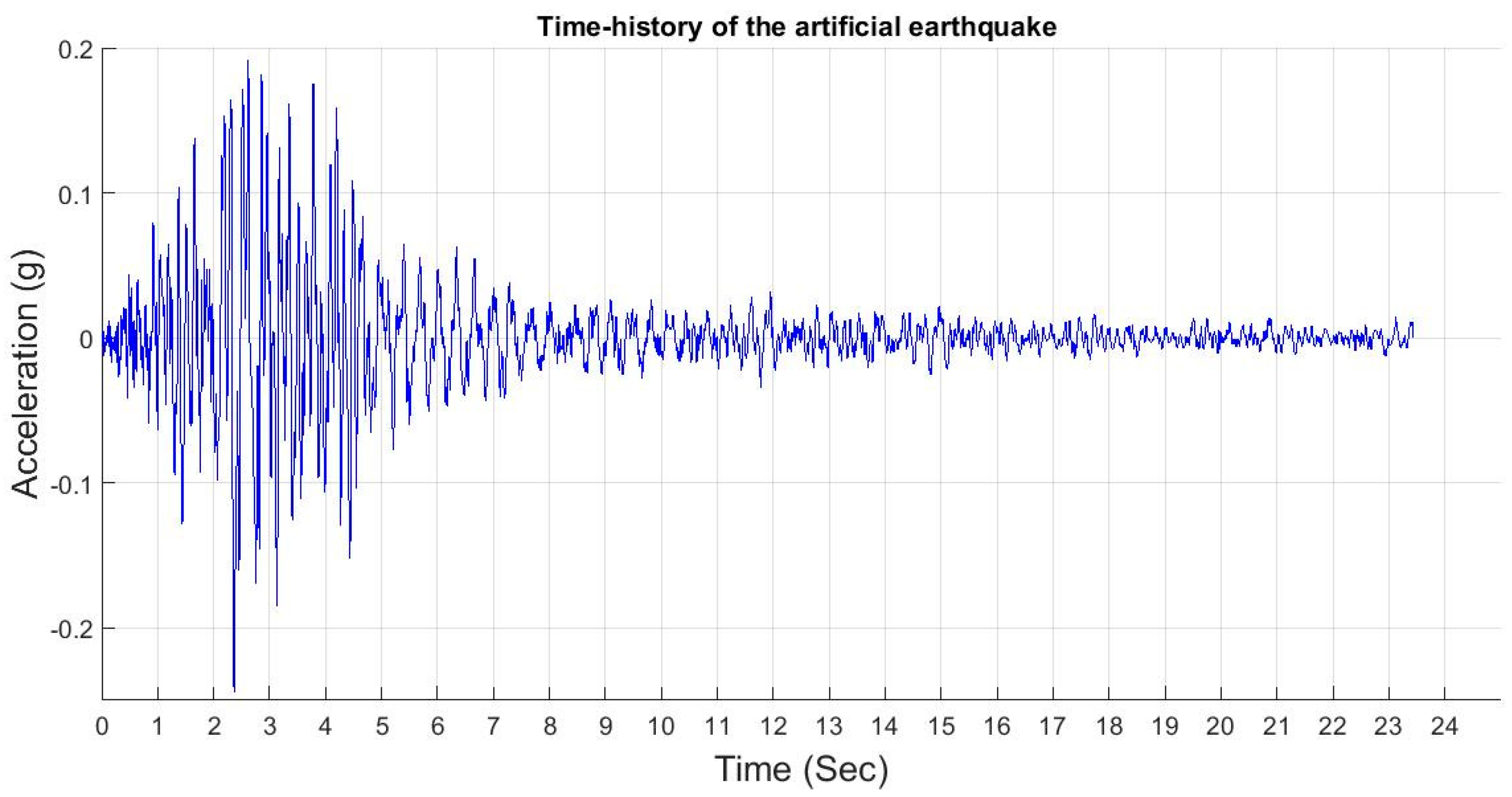
2.3. Earthquake Description
In order to realize an appropriate study on the seismic response of the structural and artificial earthquake record, a maximum acceleration of 0.24 g was selected, which represents properties close to the riskiest zone in Morocco (Zone 3) [
18] and which, for this reason, is used for the design of civil engineering structures.
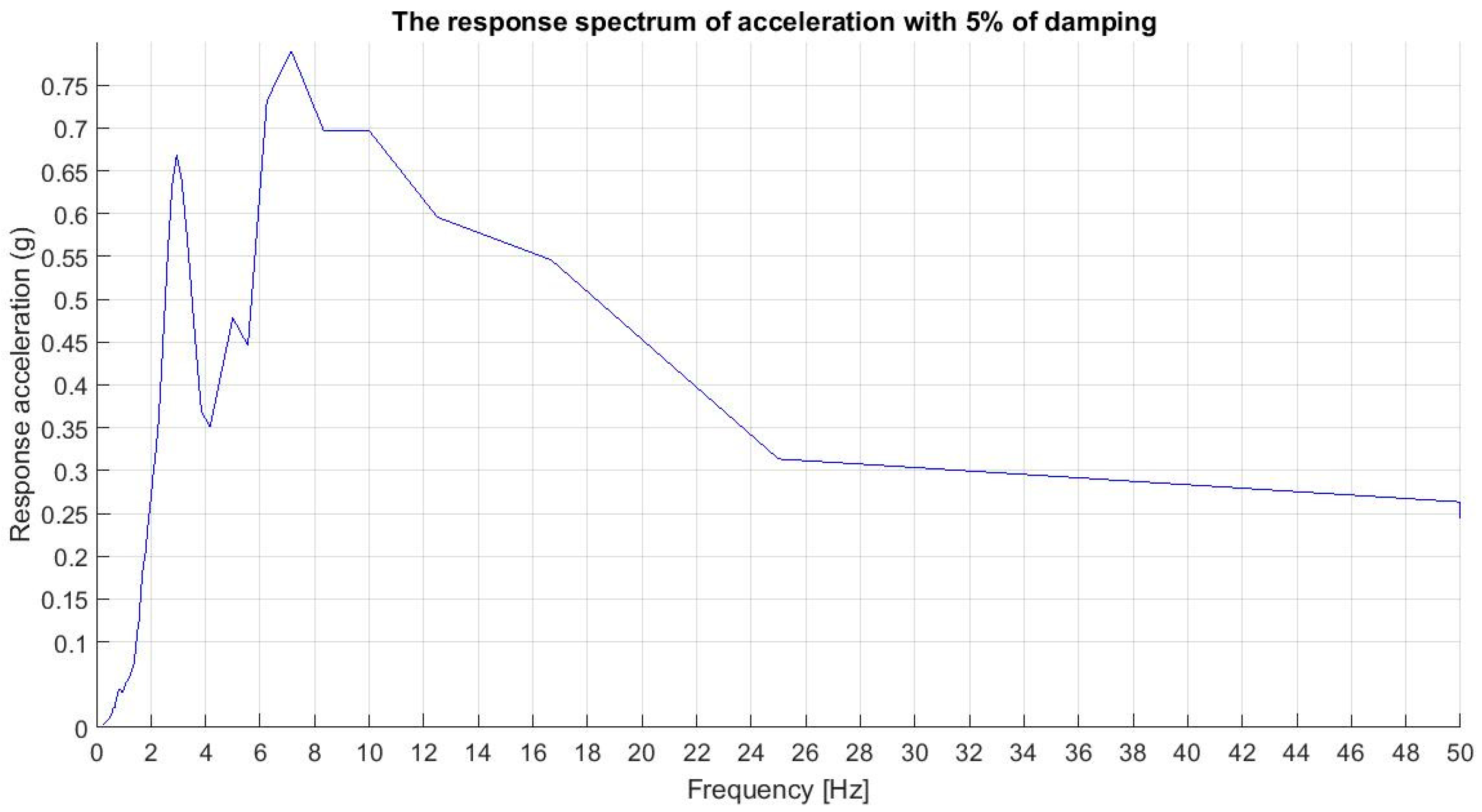
The characteristics of the earthquake chosen for this study are presented in the
Figure 2 and
Figure 3 below.
The dynamic input is applied at internal gridpoints of the bottom of the model. Wave reflections at model boundaries are minimized by specifying free-field boundary conditions.
2.4. Damping
In this study, critical damping of 5% was taken into account according to the seismic code [
18] which suggests 5% critical damping values for concrete structures and a damping interval for the construction that varies between 2 and 8% [
19]. In addition, it was defined in the literature as an estimated value of the critical damping for the soil [
20,
21].
Roy and Dutta in 2010 studied the damping due to SSI on the response of the structure over a critical damping range of 2% to 30% [
22], and it was noted that high values of damping do not give significant differences with critical damping of 5% [
23].
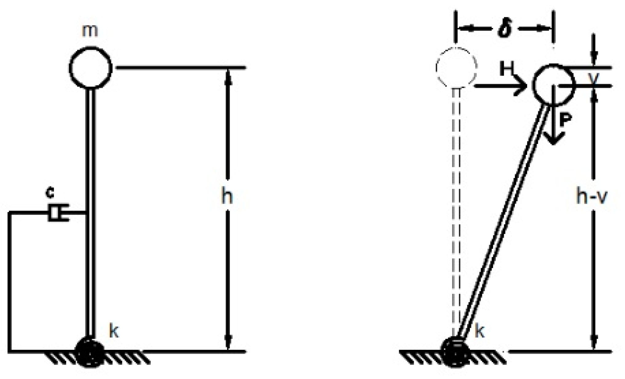
2.5. Concept of the Second-Order Effect (P-delta Effect)
Basic parameters associated with the second-order effect are shown in
Figure 4 and include a mass, m and a weight,
P, associated with a rigid column with a flexible connection at the base. In order to take into account the viscous damping, a dumper is connected to the structure. Under the action of the lateral loads
V, the overturning moment applied, without taking into account the effect P-delta equal to
V.h.
δ marks the horizontal displacement caused by the force
V. The additional overturning moment induced by the effect of the second order will be generated by the normal force P and the distance δ, and the resulting moment
M’ is given by the following expression:
Consequently, a reduction in effective stiffness affects the structure from the inclusion of the P-Δ effect [
24].
3. Results and Discussion
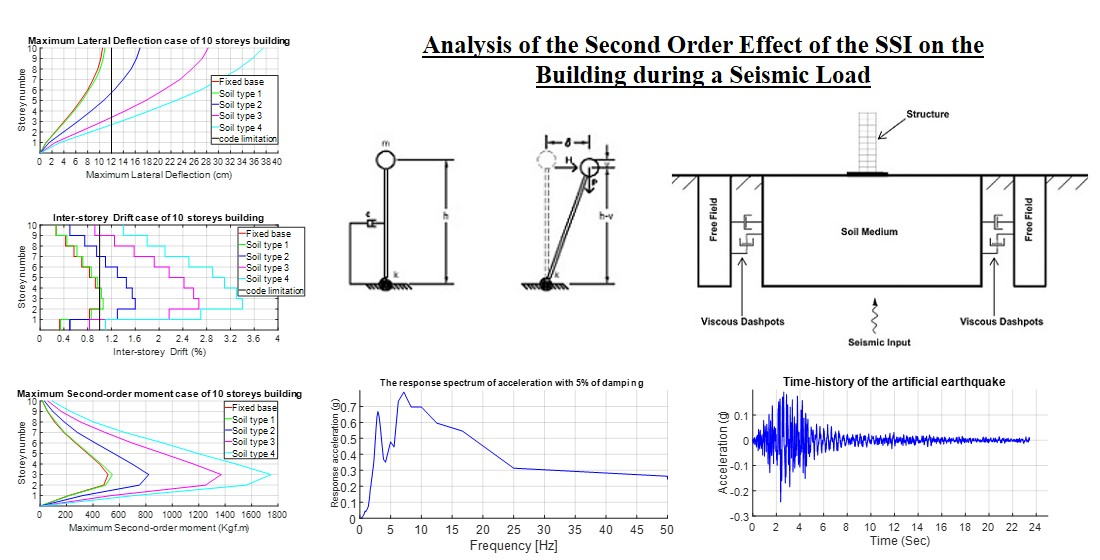
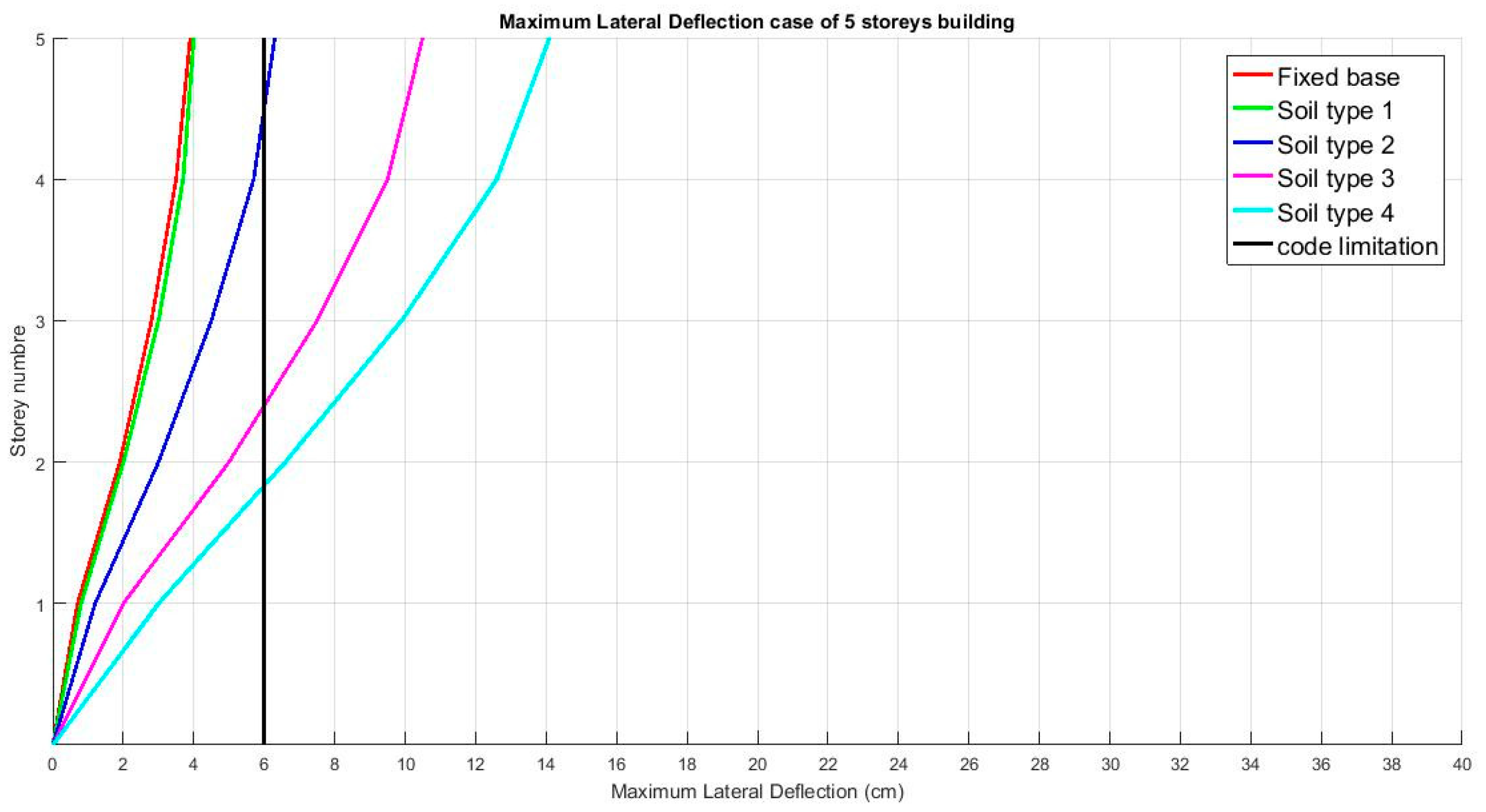
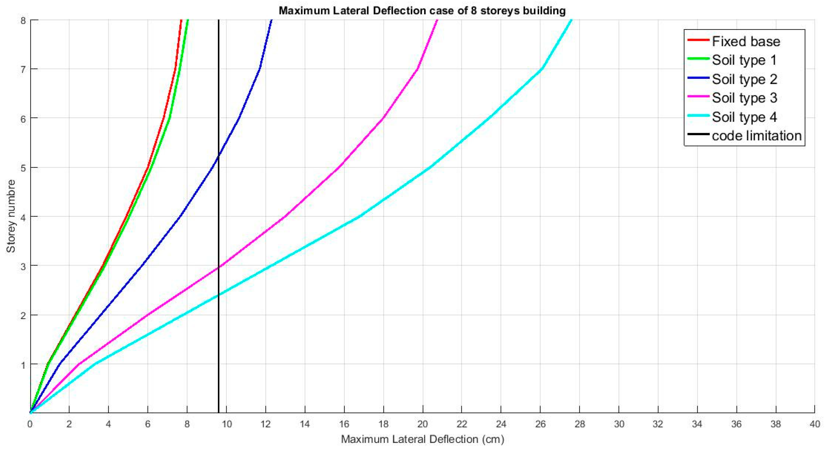
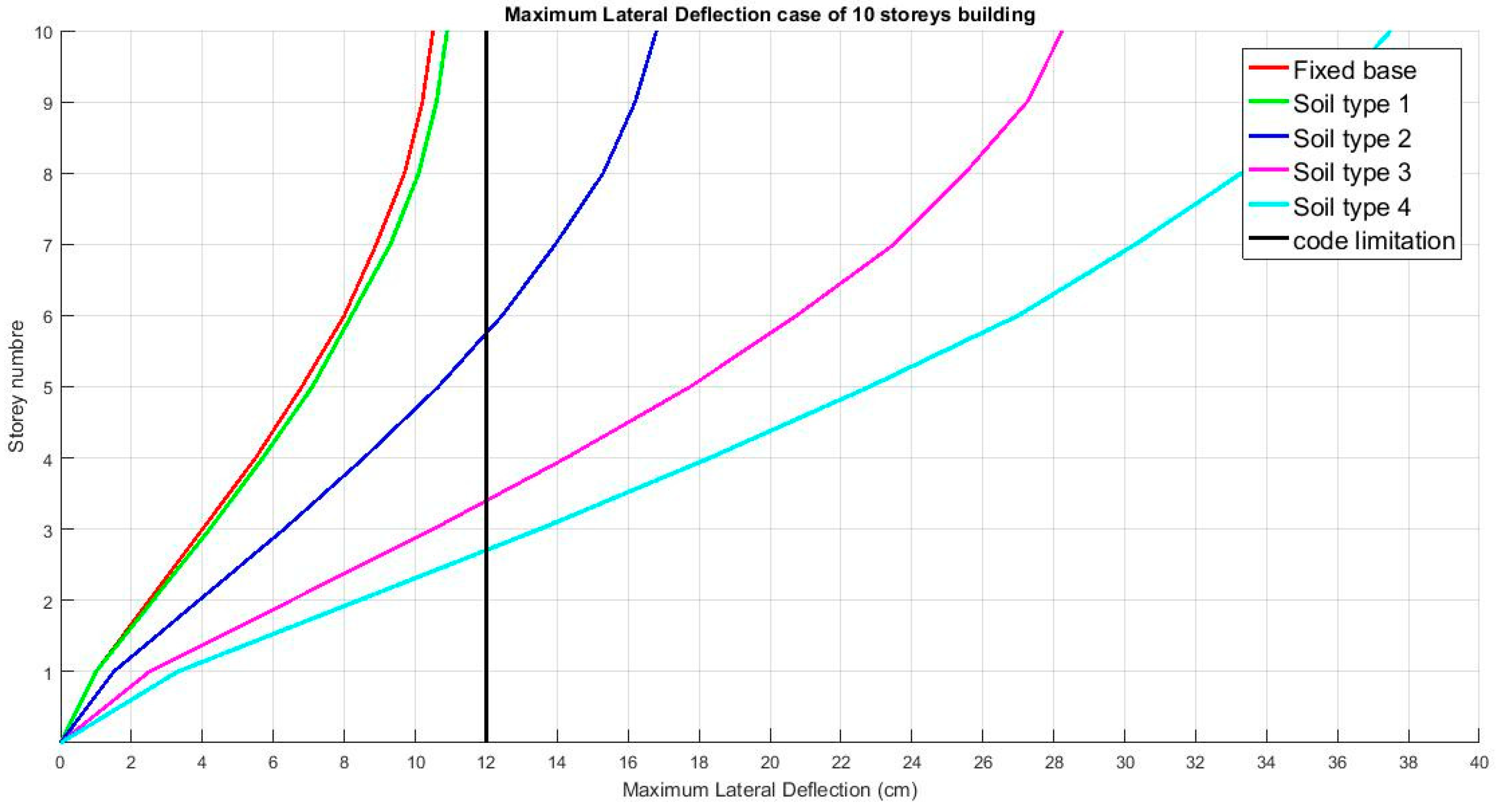
3.1. Lateral Deflection Results
The lateral deflection shown below represents the maximum at the last story level. The limit of the displacement is given by the code, which is about 0.4% of the overall height of the structure [
24].
As shown in
Figure 5,
Figure 6 and
Figure 7, the displacement increases with the decrease of the ground stiffness in the different cases and also with the increase of the height of the structure.
It can also be noticed that the non-cohesive soil (type 1) has practically the same value as the fixed base case.
Comparing the results of the maximum displacements of the fixed base and the other soil type models, we can observe that the effects of the SSI increase the displacements considerably between the 5-story and 8-story cases. It increases by 96% at the 5-story level for the soil type 4, which is less than between the 8-story and 10-story cases which increase by 37% at the 5-story level of soil type 4.
It is observable that the case of soil type 1 does not present any difference in displacement values with the fixed base for the three cases, which proves that the fixed base is only valid with a non-cohesive soil.
In addition, we can observe that in all cases, we exceeded the limit value of the code but it is amplified with the increasing story structure and the decreasing soil rigidity.
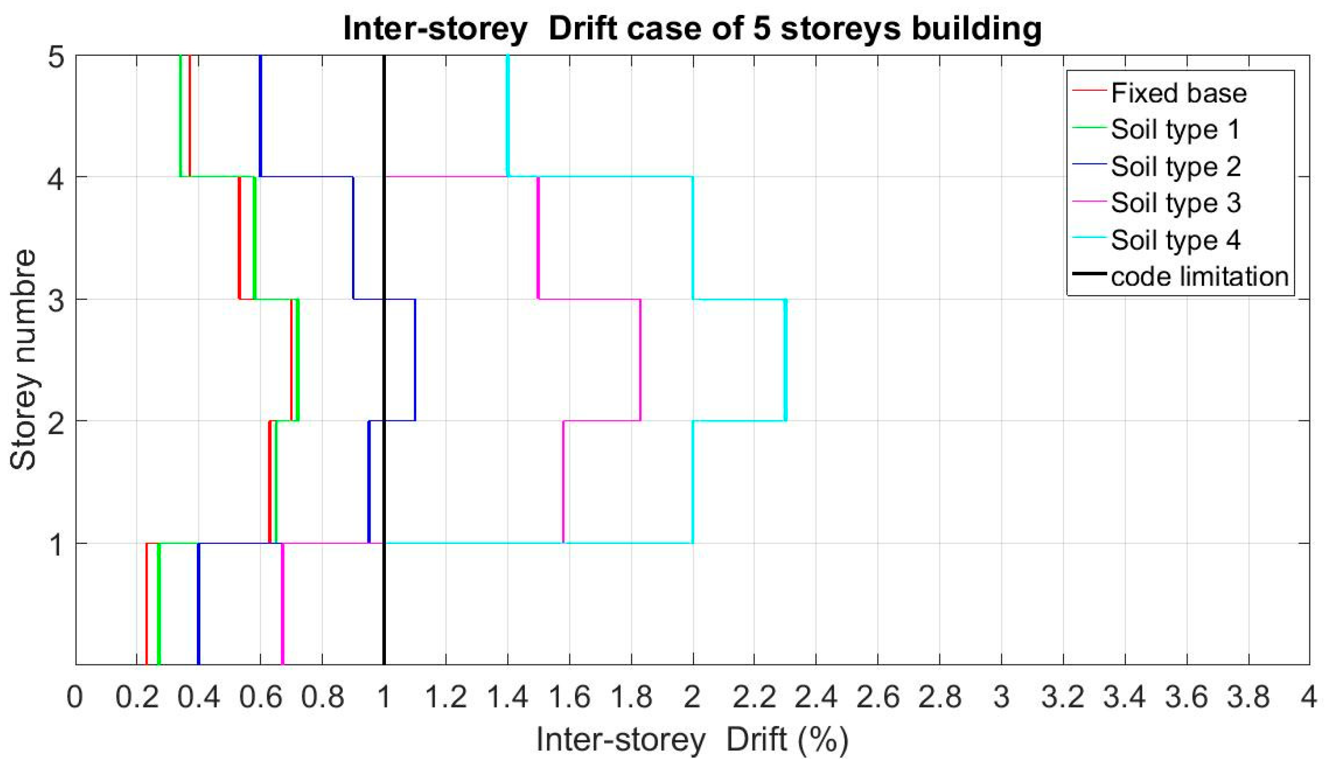
3.2. Inter-Story Drift Results
The inter-story drift mentioned below is calculated by the following:
The limitation of the code in our case is given by 1% [
25].
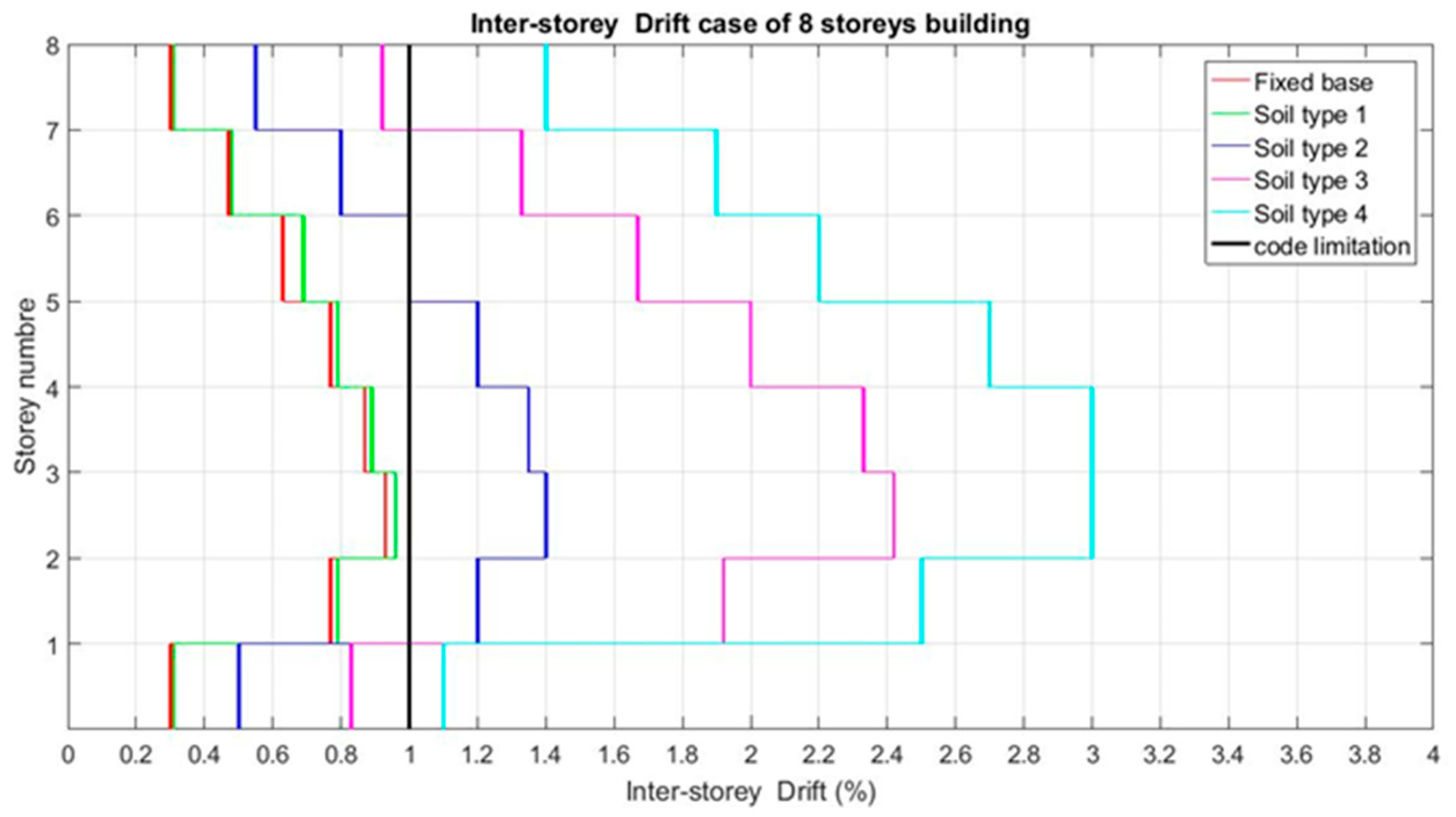
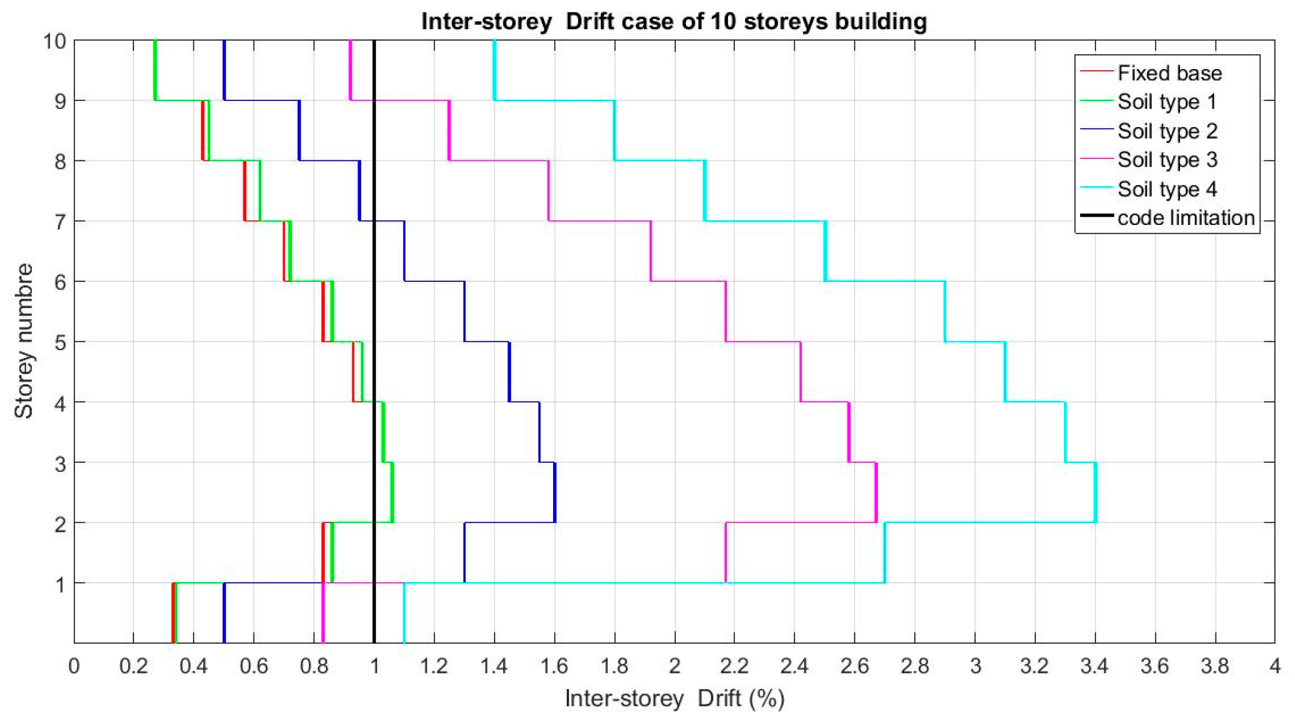
As the figures show, the inter-story drift increases considerably between levels 1 and 2 (
Figure 8,
Figure 9 and
Figure 10), with a small difference between the case of rigid soil (non-cohesive soil) and the embedded base case.
This indicates that the non-cohesive soil (type 1) has practically a similar behavior compared to the fixed base.
Comparing the results of the inter-story drifts between the fixed base and the other soil cases, the following results of the difference between the maximum and minimum values can be observed:
For the case of 5 stories, a difference of 0.4%; for the case of embedding and soil type 1, as well as the case of soil type 4, a difference of 1.3%.
For the case of 8 stories, a difference of 0.4%; for the embedded case and floor type 1, as well as the case of floor type 4, a difference of 1.9%.
For the case of 10 stories, a difference of 0.8%; for the embedded case and floor type 1, as well as the case of floor type 4, a difference of 2.3%.
The above results show that the inter-story drifts are amplified between the intermediate levels, which will generate second-order solicitations that are not inconsiderable.
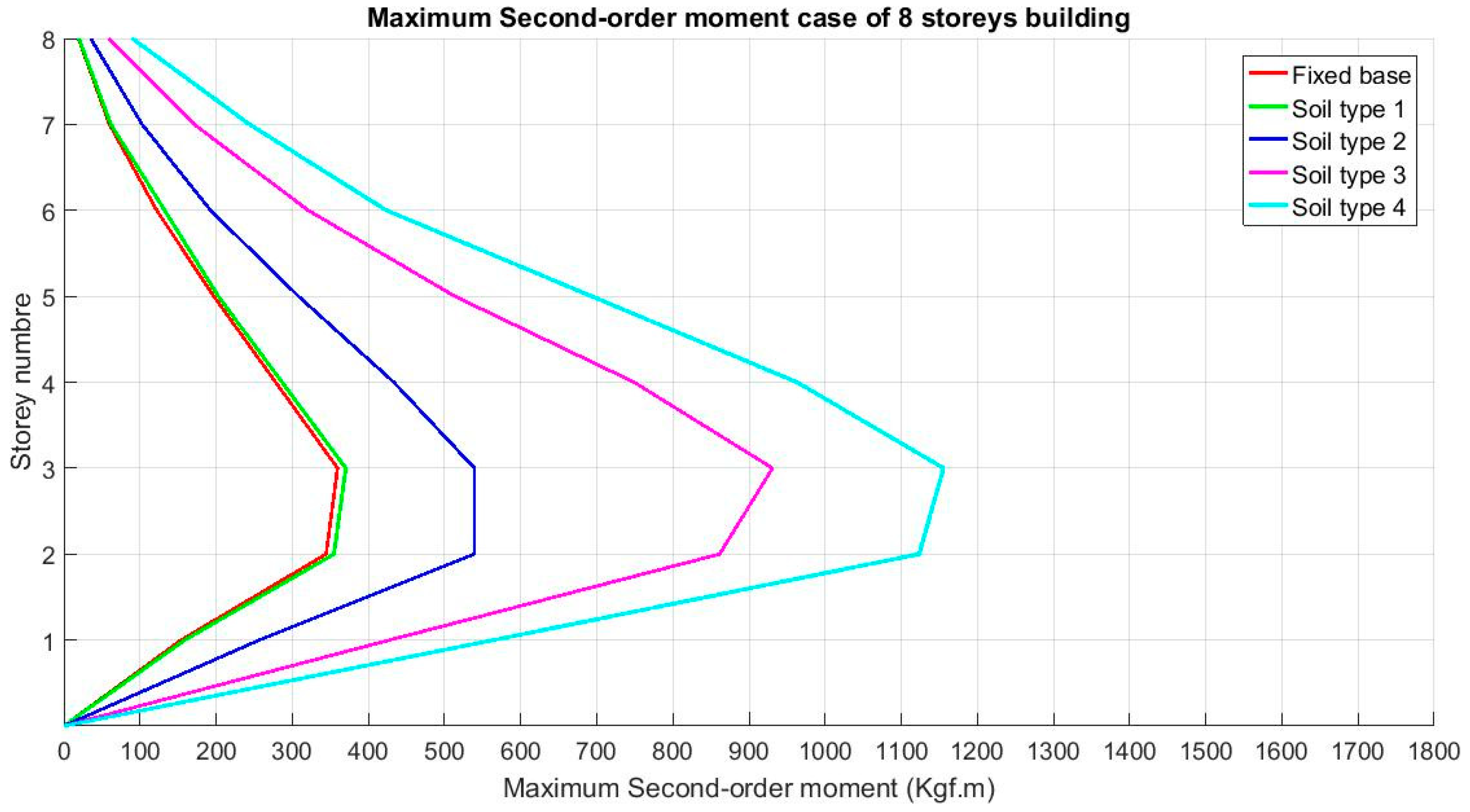
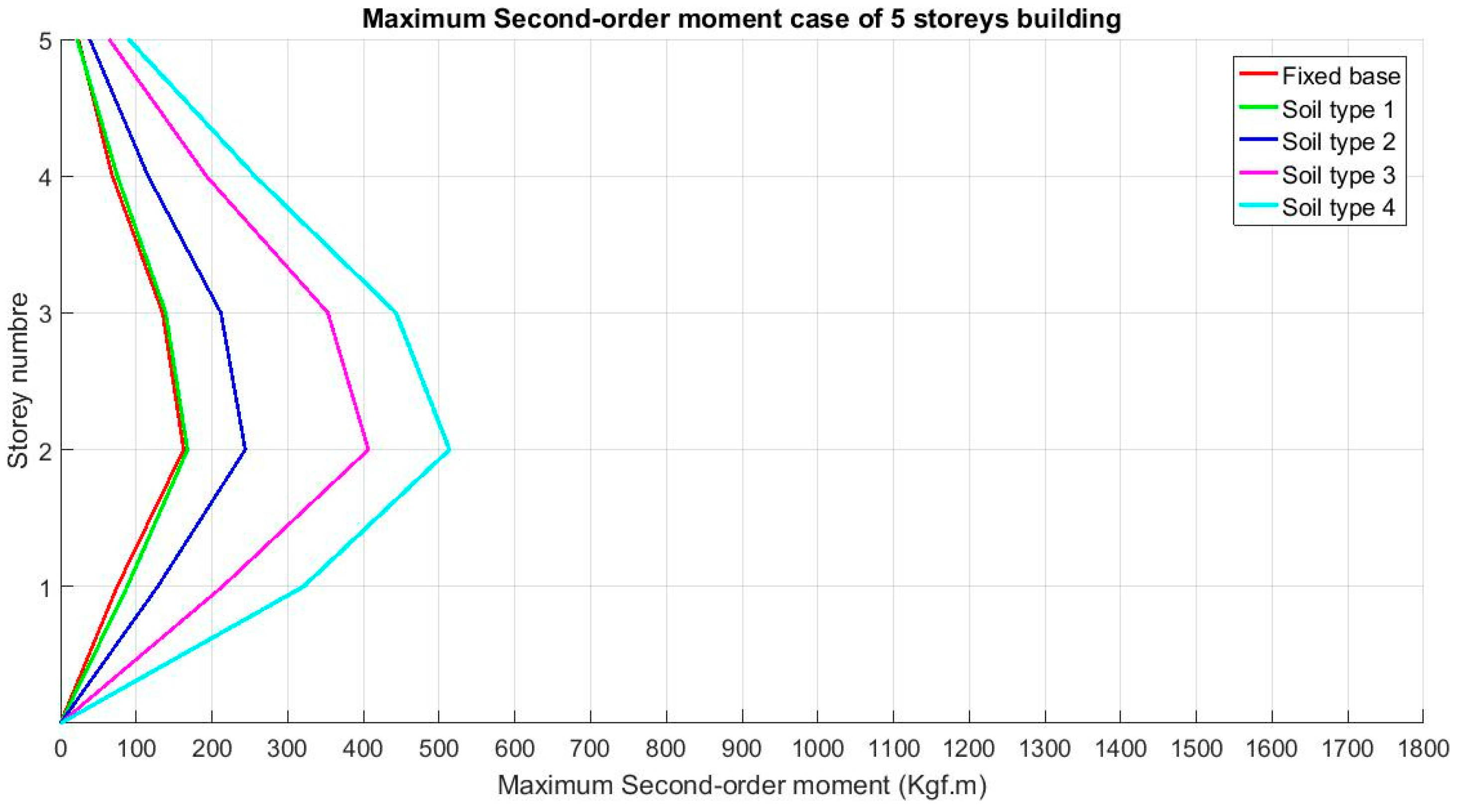
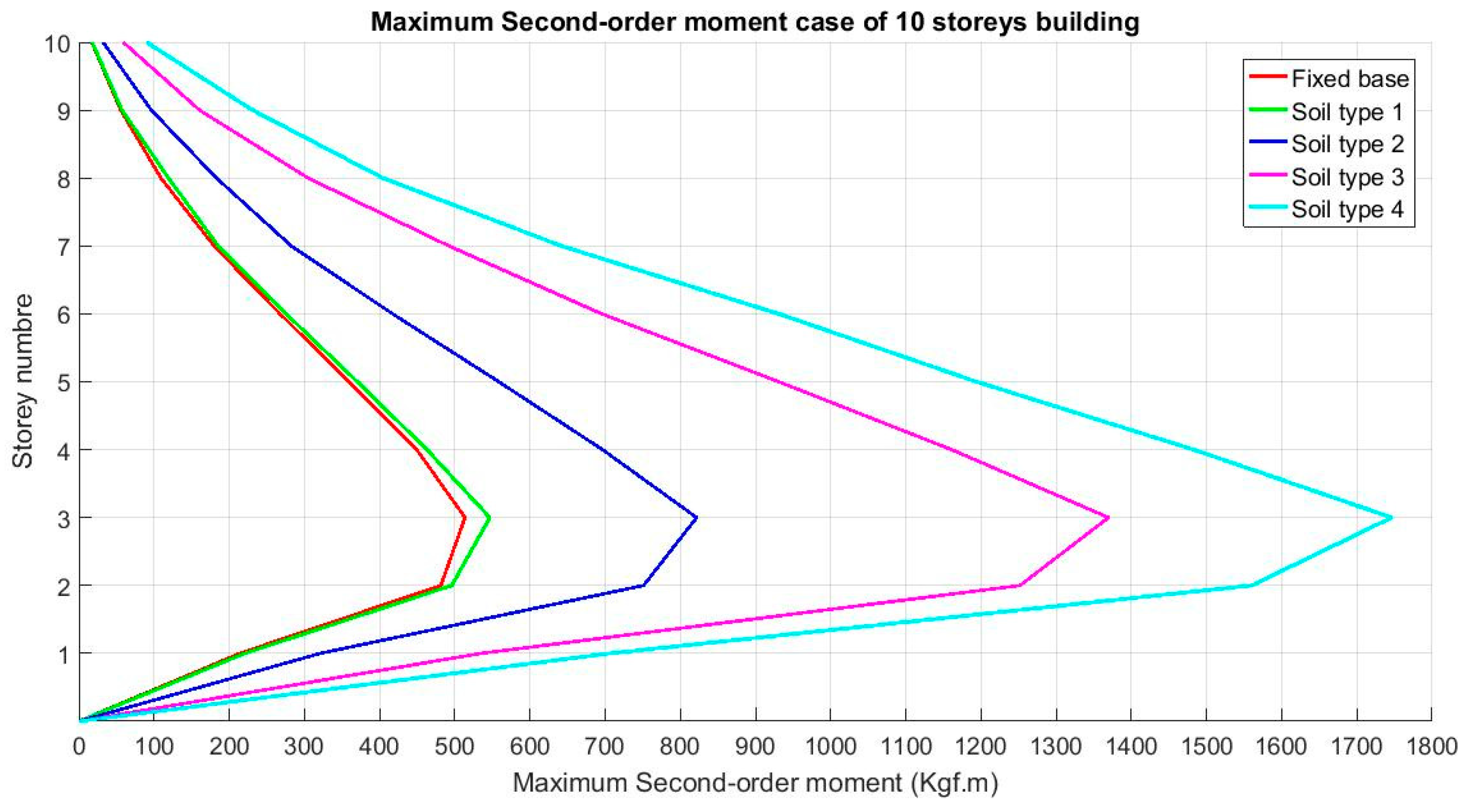
3.3. Maximum Second-Order Moment Results
As shown in the figures, the values of the second-order moments increase considerably in the intermediate levels (
Figure 11,
Figure 12 and
Figure 13), with identical values between the case of a non-cohesive floor (type 1) and the embedded base case, except for a small increase on the third floor for the 10 stories case. This indicates that the non-cohesive soil has behavior almost similar to a fixed base.
By comparing the results of the second-order moments between the fixed base and the other soil cases, the following results can be observed:
For the case of 5 stories, an increase of 233% between the fixed base case and the soil type 4 case, with a maximum value at the second-floor level.
For the case of 8 stories, an increase of 228% between the fixed base case and the soil type 4 case, with a maximum value at the third-floor level.
For the case of 10 stories, an increase of 250% between the fixed base case and the soil type 4 case, with a maximum value on the third-floor.
The above results show that the increases in second-order loads between the fixed base case and the soil type 4 case are proportional but present significant values when the height increases and the soil stiffness decreases.
4. Conclusions
In this paper, a soil–structure interaction model has been developed, using finite difference software (FLAC 2D), which is a powerful tool for this type of analysis.
Our purpose was to understand the second-order effects through a step-by-step analysis of displacements, according to the results presented previously. We find that the rigid non-cohesive soil type has almost identical properties to an embedding base during a seismic load. This result may somewhat relax structural engineers during their engineering studies, but the dynamic soil–structure interaction has dangerous effects on the increase in the number of floors and the decrease in soil stiffness.
We also find that the effect of the SSI amplified the second-order loads that proportionally change with the case the embedded base. This result can be taken into account during the engineering analysis in order to predict a structure more resistant to these effects.
It should be noted that, in this study, the effects of SSI in the case of rigid and non-cohesive soils is negligible, and on the other hand, for cohesive soil types, these effects cannot in any case be underestimated.
Author Contributions
Conceptualization, E.M.E., H.B. and A.E.O.; methodology, E.M.E. and A.E.O.; software, E.M.E. and A.E.O.; validation, M.R., M.C. and F.H.C.; formal analysis, E.M.E. and A.E.O.; investigation, E.M.E. and A.E.O.; resources, E.M.E. and A.E.O.; data curation, M.R. and M.C.; writing—original draft preparation, E.M.E.; writing—review and editing, E.M.E. and A.E.O.; visualization, E.M.E. and A.E.O.; supervision, M.R., M.C. and F.H.C.; project administration, M.R.; funding acquisition, M.R. All authors have read and agreed to the published version of the manuscript.
Funding
This research received no external funding.
Acknowledgments
This paper and the research behind it would not have been possible without the exceptional support of my supervisor, Rougui Mohamed, Chourak Mimoun and Fadi Hage Chehade. there enthusiasm, knowledge and exacting attention to detail have been an inspiration and kept my work on track from my first to the final draft of this paper. Abdelday El Omari, for his help for the numerical modal and answered with unfailing patience numerous questions. Hasnae Boubel, my colleague at Mohamed V University, have also looked over my transcriptions.
Conflicts of Interest
The authors declare no conflict of interest.
References
- Edip, K.; Garevski, M.; Sheshov, V.; Bojadjieva, J. Boundary Effects in Simulation of Soil-Structure Interaction Problems. Soil Mech. Found. Eng. 2017, 54, 239–243. [Google Scholar] [CrossRef]
- Shanmugam, J.; Dode, P.A.; Chore, H.S. Analysis of Soil Structure Interaction in Framed Structure. Int. J. Comput. Appl. 2015, 975, 8887. [Google Scholar]
- Kwag, S.; Ju, B.; Jung, W. Beneficial and Detrimental Effects of Soil-Structure Interaction on Probabilistic Seismic Hazard and Risk of Nuclear Power Plant. Adv. Civ. Eng. 2018, 2018, 1–18. [Google Scholar] [CrossRef]
- Mylonakis, G.; Gazatas, G. Seismic soil-structure interaction: Beneficial or detrimental? J. Earthq. Eng. 2000, 4, 277–301. [Google Scholar] [CrossRef]
- Far, H. Dynamic behaviour of unbraced steel frames resting on soft ground. Steel Constr. 2019, 12, 135–140. [Google Scholar] [CrossRef]
- Saha, R.; Dutta, S.C.; Haldar, S.; Kumar, S. Effect of soil-pile raft-structure interaction on elastic and inelastic seismic behaviour. Structures 2020, 26, 378–395. [Google Scholar] [CrossRef]
- Shehu, R.; Angjeliu, G.; Bilgin, H. A Simple Approach for the Design of Ductile Earthquake-Resisting Frame Structures Counting for P-Delta Effect. Buildings 2019, 9, 216. [Google Scholar] [CrossRef] [Green Version]
- Montgomery, C.J. Influence of P-Delta effects on seismic design. Can. J. Civ. Eng. 1981, 8, 31–43. [Google Scholar] [CrossRef]
- Lysmer, J.; Kuhlemeyer, R.L. Finite dynamic model for infinite media. J. Eng. Mech. Div. ASCE 1969, 95, 859–877. [Google Scholar]
- Dutta, C.H.; Roy, R. A critical review on idealization and modelling for interaction among soil–foundation–structure system. Comput. Struct. 2002, 80, 1579–1594. [Google Scholar] [CrossRef]
- Zhang, X.; Wegner, J.L.; Haddow, J.B. Three-dimension dynamic soil–structure interaction analysis in the time domain. Earthq. Eng. Struct. Dyn. 1999, 28, 1501–1524. [Google Scholar] [CrossRef]
- Seo, C.G.; Yuna, C.B.; Kimb, J.M. Three-dimensional frequency-dependent infinite elements for soil–structure interaction. Eng. Struct. 2007, 29, 3106–3120. [Google Scholar] [CrossRef]
- Zheng, J.; Takeda, T. Effects of soil-structure interaction on seismic response of PC cable-stayed bridge. Soil Dyn. Earthq. Eng. 1995, 14, 427–437. [Google Scholar] [CrossRef]
- Galal, K.; Naimi, M. Effect of conditions on the response of reinforced concrete tall structures to near fault earth-quakes. Struct. Des. Tall Spec. Build. 2008, 17, 541–562. [Google Scholar] [CrossRef]
- Tabatabaiefar, S.H.R.; Fatahi, B.; Samali, B. An empirical relationship to determine lateral seismic response of mid-rise building frames under influence of soil-structure interaction. Struct. Des. Tall Spec. Build. 2014, 23, 526–548. [Google Scholar] [CrossRef]
- Far, H.; Fatahi, B.; Samali, B. Numerical and Experimental Investigations on Seismic Response of Building Frames under Influence of Soil-Structure Interaction. Adv. Struct. Eng. 2014, 17, 109–130. [Google Scholar]
- Far, H.; Fatahi, B. Idealisation of soil–structure system to determine inelastic seismic response of mid-rise building frames. Soil Dyn. Earthq. Eng. 2014, 66, 339–351. [Google Scholar] [CrossRef]
- Moroccan Earthquake Regulations; RPS 2000; Ministry of Housing and the Development of Space: Rabat, Morocco, 2000.
- Veletsos, A.S.; Meek, J.W. Dynamic behavior of building—Foundation systems. Earthq. Eng. Struct. Dyn. 1974, 3, 121–138. [Google Scholar] [CrossRef]
- Velez, A.; Gazetas, G.; Krishnan, R. Lateral Dynamic Response of Constrained-Head Piles. J. Geotech. Eng. 1983, 109, 1063–1081. [Google Scholar] [CrossRef]
- Gazetas, G. Formulas and Charts for Impedances of Surface and Embedded Foundations. J. Geotech. Eng. 1991, 117, 1363–1381. [Google Scholar] [CrossRef]
- Roy, R.; Dutta, S.C. Inelastic seismic demand of low-rise buildings with soil-flexibility. Int. J. Non Linear Mech. 2010, 45, 419–432. [Google Scholar] [CrossRef]
- Fatahi, B.; Far, H.; Samali, B. Soil-structure interaction vs. Site effect for seismic design of tall buildings on soft soil. Geomech. Eng. 2014, 6, 293–320. [Google Scholar] [CrossRef]
- Shehu, R. The p-δ-ductility effect: Overview the effectof the second order in the ductil structures. In Proceedings of the International Scientific Forum, Tirana, Albania, 12–14 December 2013; Volume 3, pp. 143–155. [Google Scholar]
- Moroccan Earthquake Code; RPS 2000; Ministry of Housing and the Development of Space: Rabat, Morocco, 2011.
| Publisher’s Note: MDPI stays neutral with regard to jurisdictional claims in published maps and institutional affiliations. |
© 2021 by the authors. Licensee MDPI, Basel, Switzerland. This article is an open access article distributed under the terms and conditions of the Creative Commons Attribution (CC BY) license (http://creativecommons.org/licenses/by/4.0/).

 ,
, 


