
Assessment of the Effectiveness of Different Safety Measures at Tunnel Lay-Bys and Portals to Protect Occupants in Passenger Cars


Abstract
:
1. Introduction
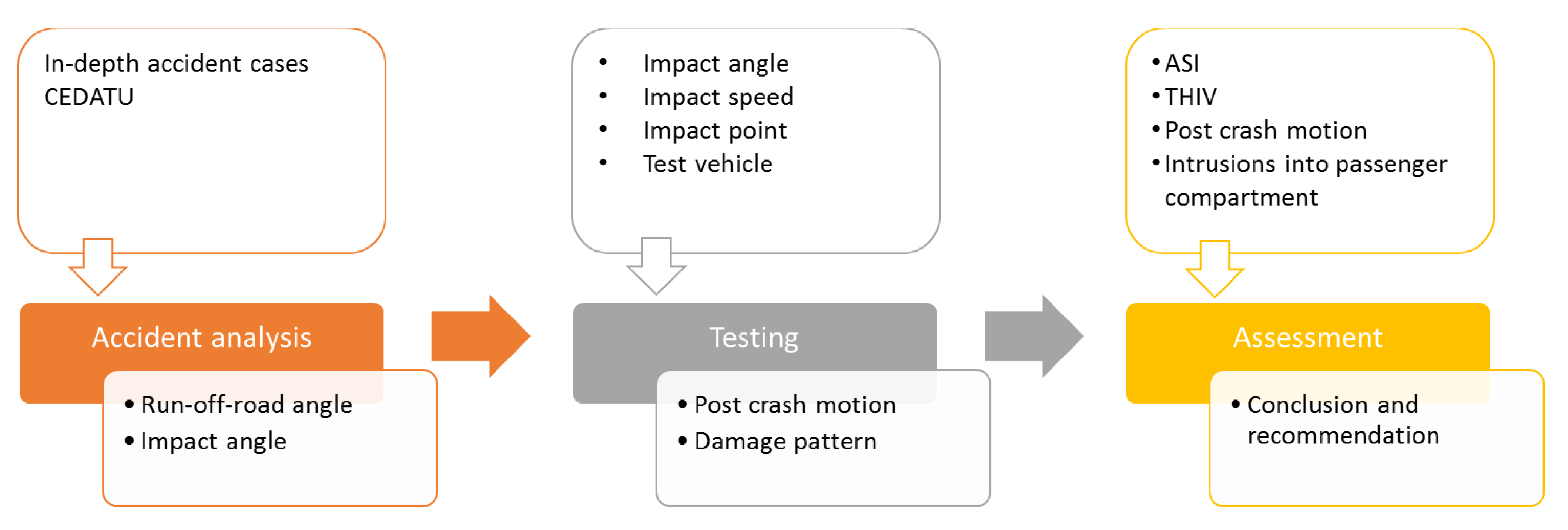
2. Materials and Methods
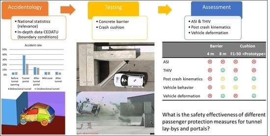
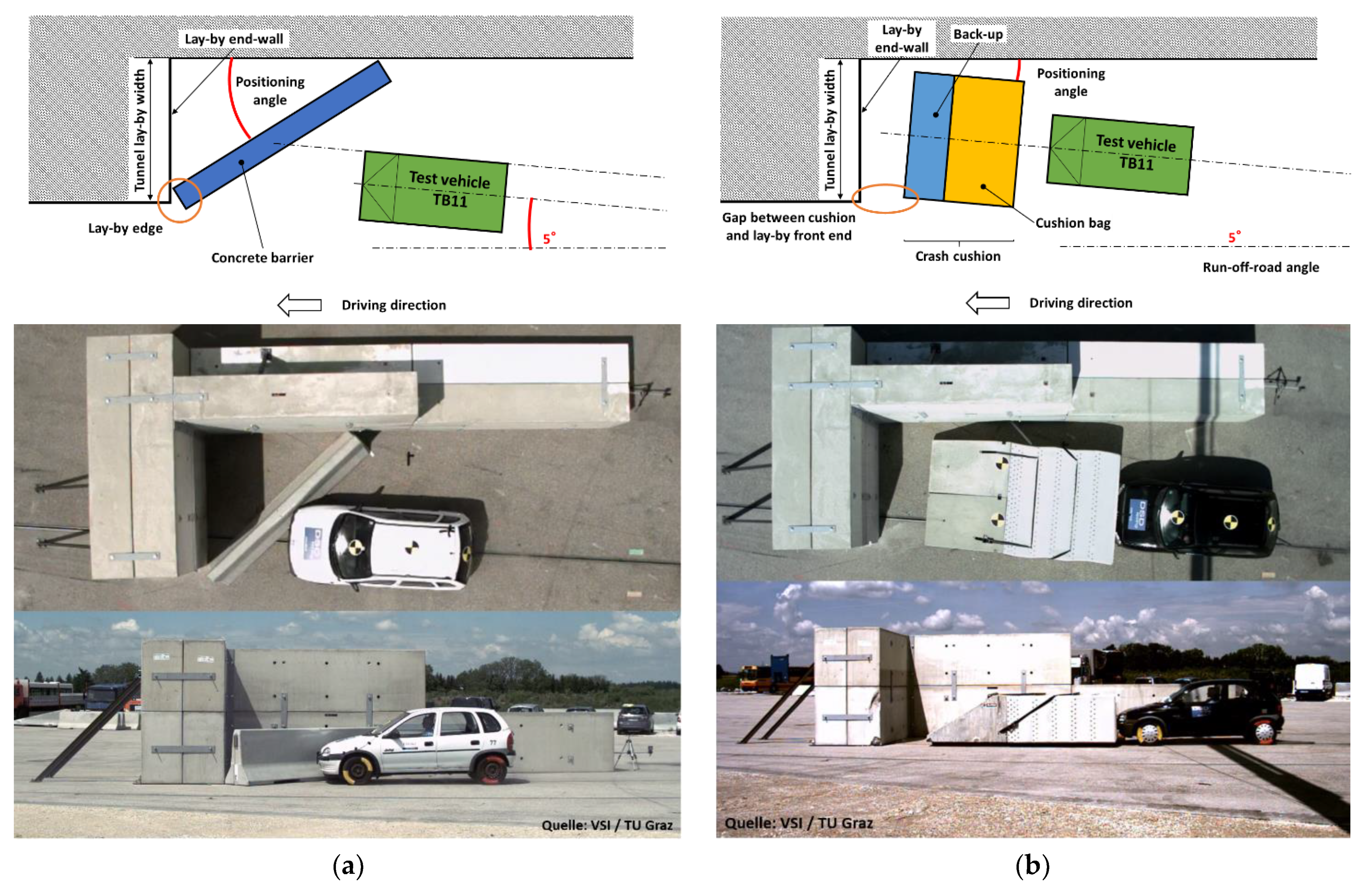
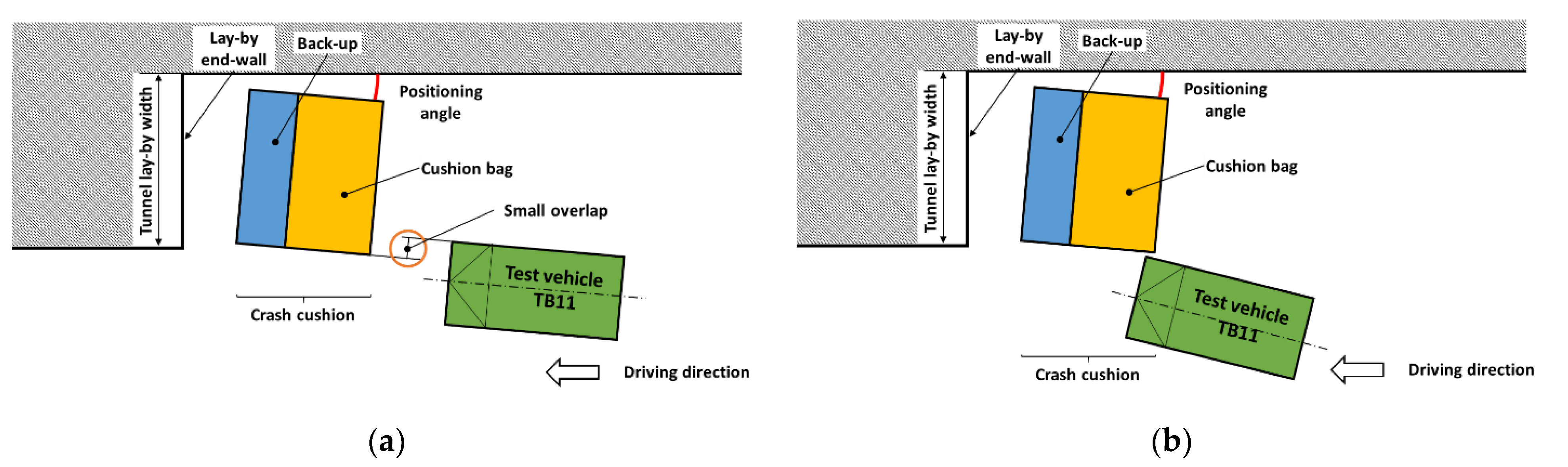
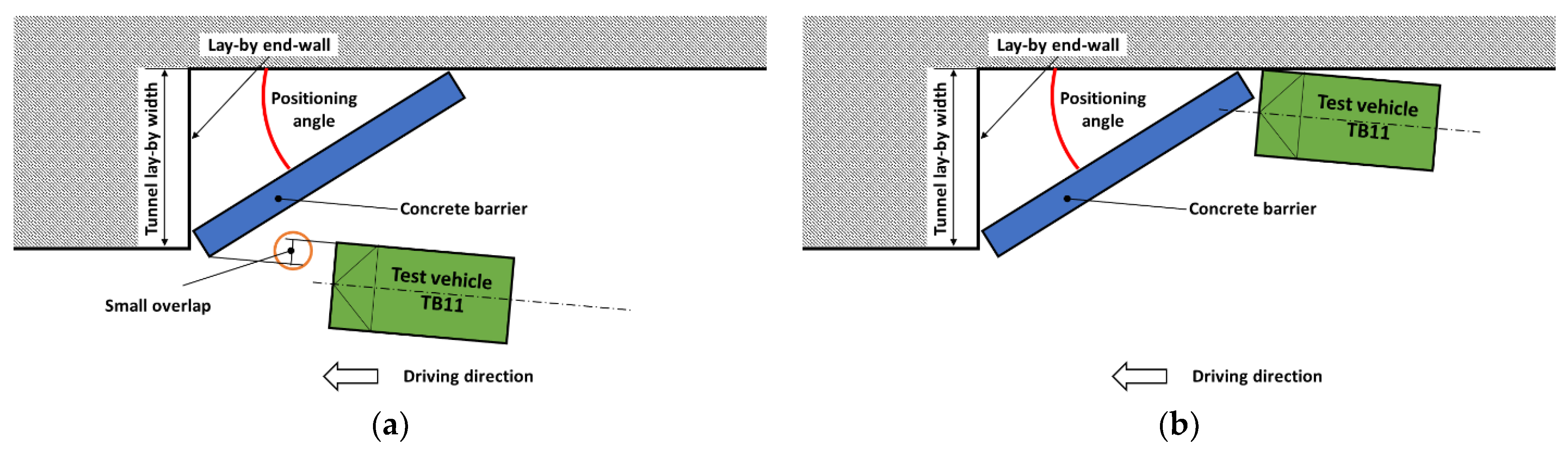
2.1. Impact Configuration
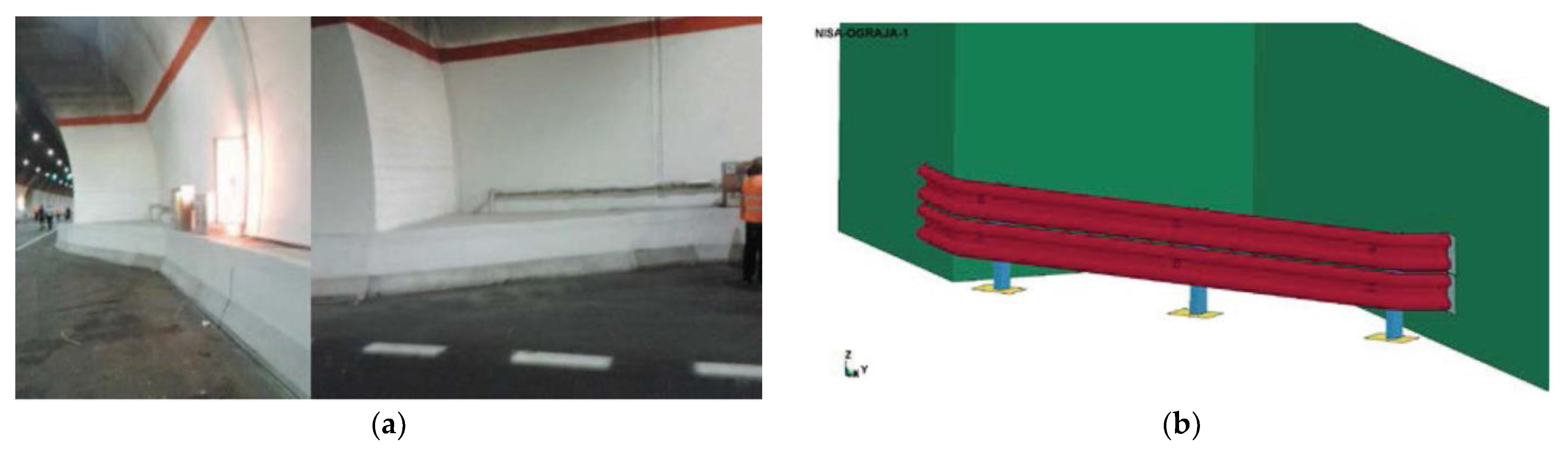
2.2. Test Specimen
2.3. Data Acquisition
2.4. Assessment
3. Results
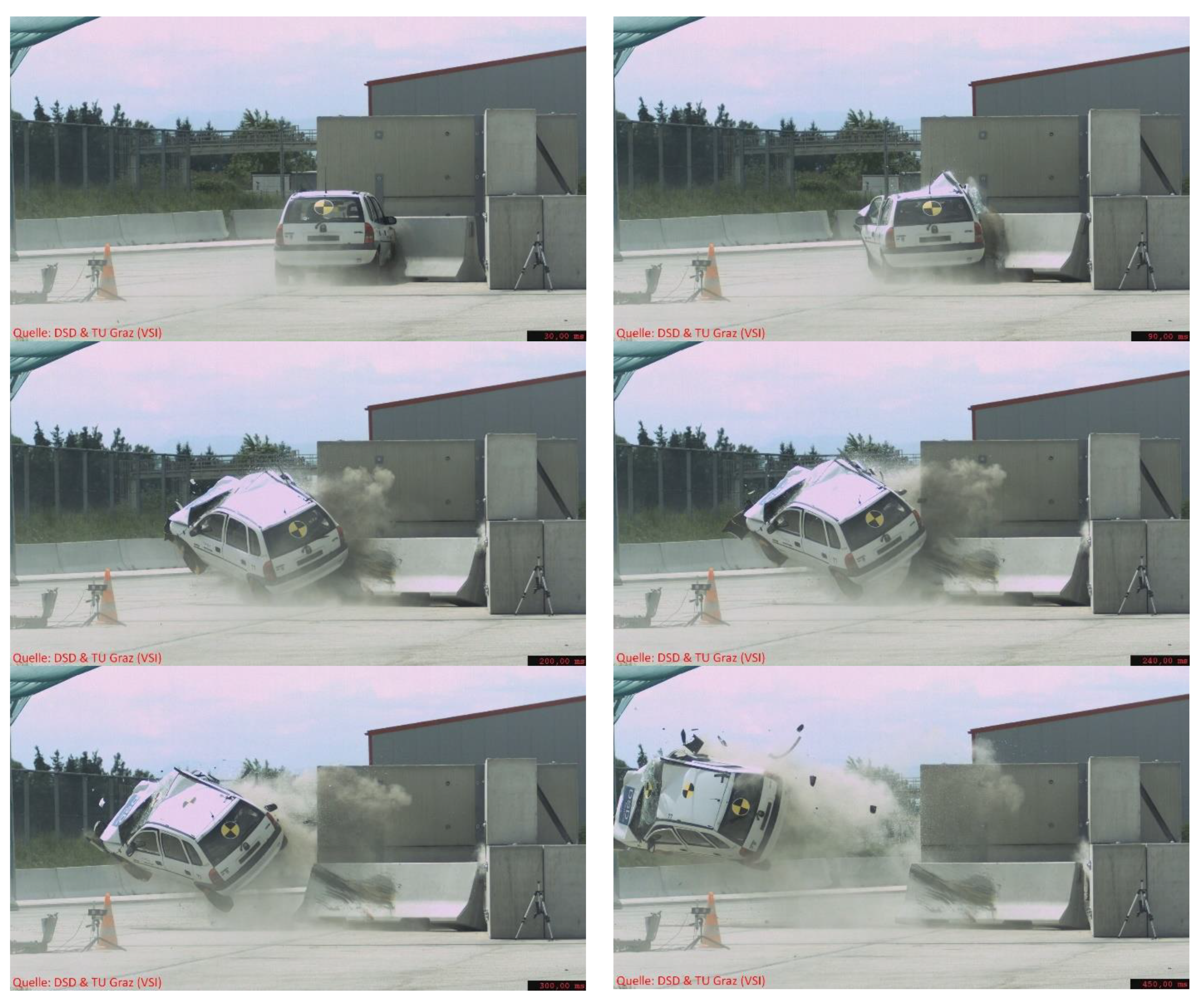
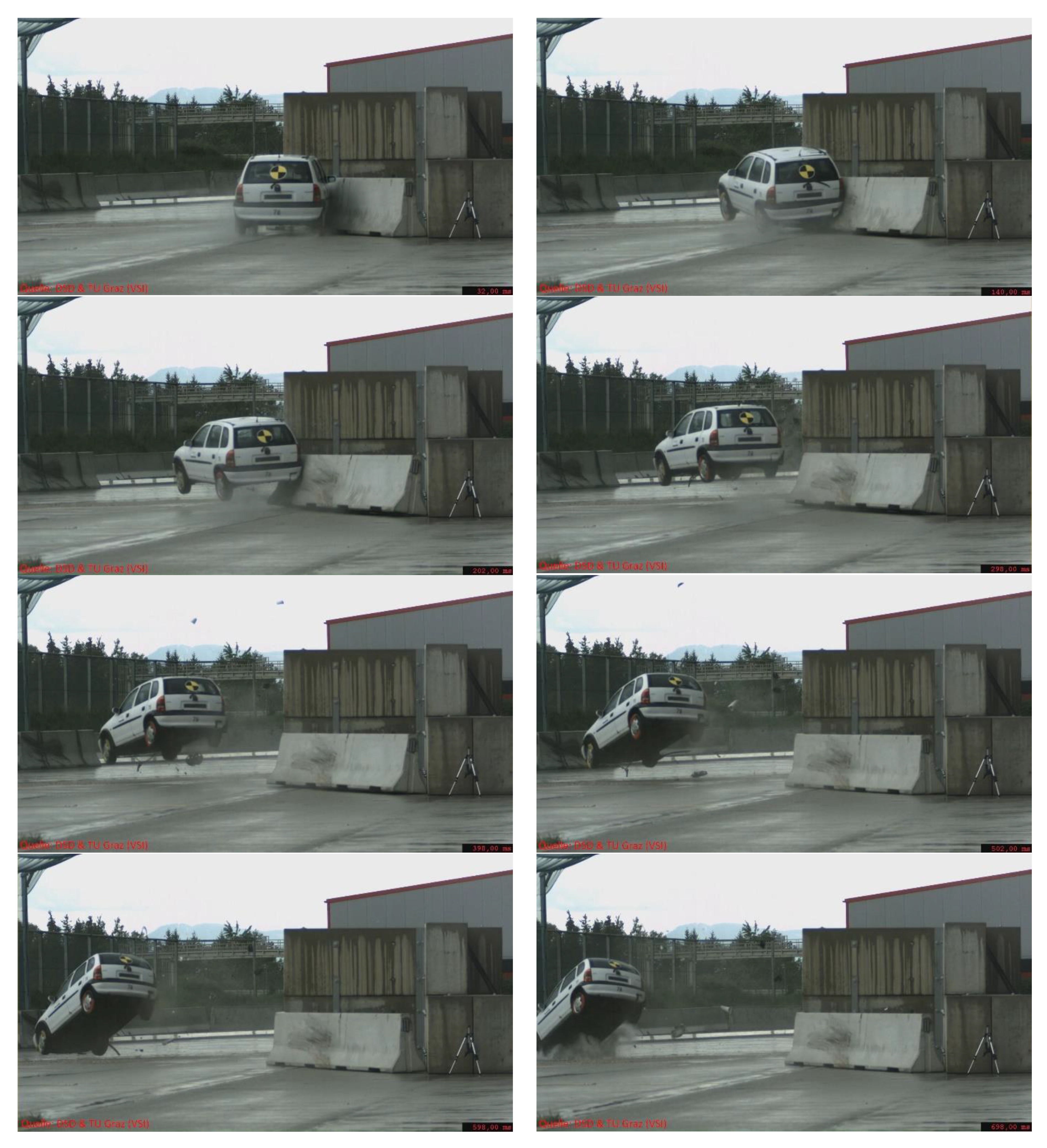
3.1. Concrete Barrier 4 m
3.2. Concrete Barrier 8 m
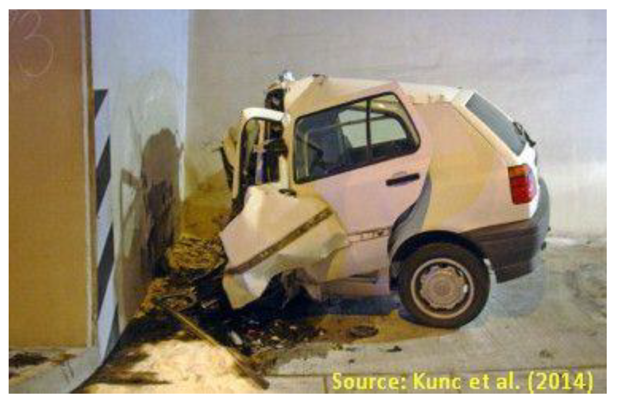
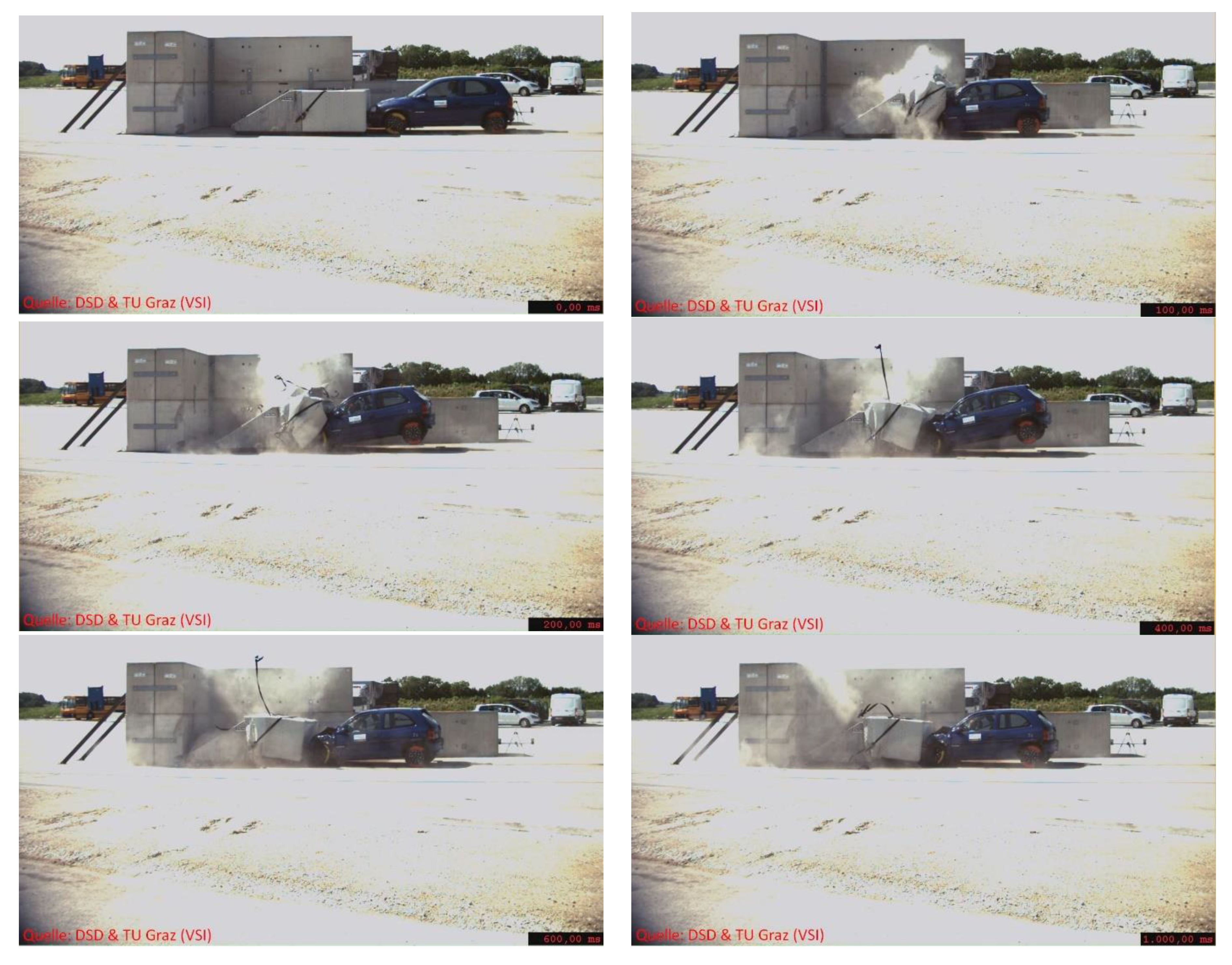
3.3. Crash Cushion Alpina F1-50
3.4. Crash Cushion Alpina <prototype>
3.5. Summary of the Test Results
4. Discussion
5. Limitations
6. Conclusions
- Crash cushion Alpina <prototype> (not designed for this speed limit)
- 8 m concrete barrier
- Crash cushion Alpina F1-50 (not designed for this speed limit)
- 4 m concrete barrier (should nothing else be available, which can be used to protect vehicle occupants on crash impacts)
Author Contributions
Funding
Institutional Review Board Statement
Informed Consent Statement
Data Availability Statement
Conflicts of Interest
References
- European Parliament; Council of the European Union. Directive 2004/54/ec of the European Parliament and of the Council on Minimum Safety Requirements for Tunnels in the Trans.-European Road Network; 2004/54/EC. European Parliament, Council of the European Union, 2004.
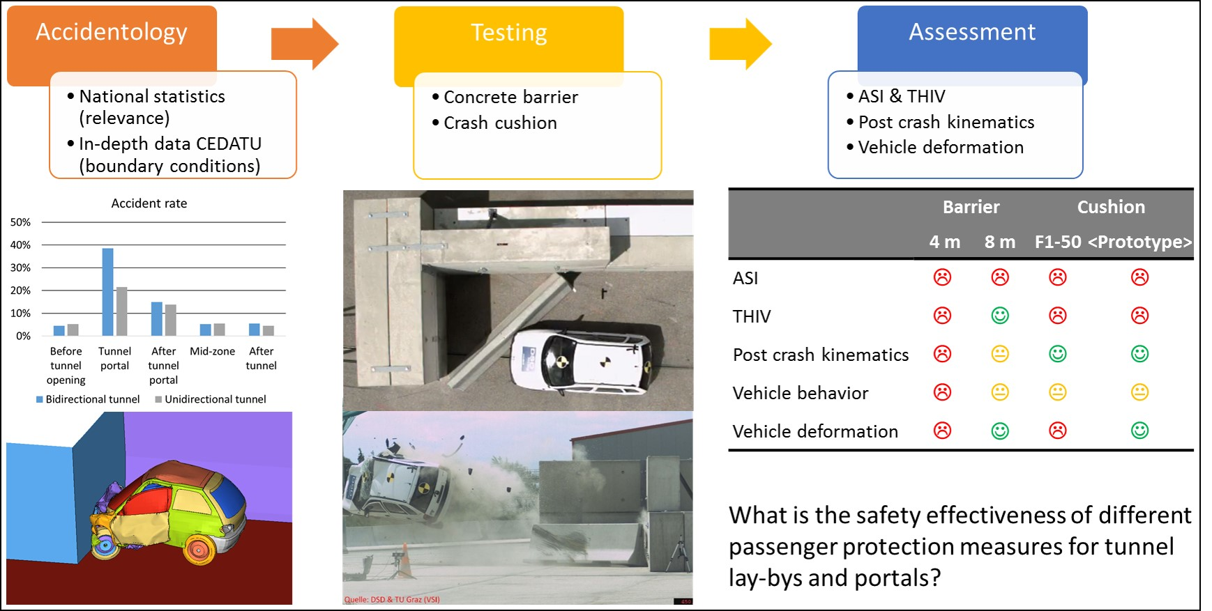
- Kunc, R.; Omerović, S.; Ambrož, M.; Prebil, I. Comparative study of European tunnel emergency-stop-area-wall protection measures. Acc. Anal. Prevent. 2014, 63, 9–21. [Google Scholar] [CrossRef]
- Strnad, B.; Schmied, S. Bericht über Brände und Unfälle in Tunnelanlagen: Bericht gemäß § 3 Abs. 8 STSG Beziehungsweise; EU-Direktive 2004/54/EG; Bundesministerium für Verkehr, Innvoation und Technologie: Wien, Austria, 2018. [Google Scholar]
- Ma, Z.-L.; Shao, C.-F.; Zhang, C.-F. Characteristics of traffic accidents in Chinese freeway tunnels. Tunnell. Undergr. Space Technol. 2009, 24, 350–355. [Google Scholar] [CrossRef]
- Mashimo, H. State of the road tunnel safety technology in Japan. Tunnell. Undergr. Space Technol. 2002, 17, 145–152. [Google Scholar] [CrossRef]
- Amundsen, F.; Engebretsen, A. Studies on Norwegian Road Tunnels II an Analysis on Traffic Accidents in Road Tunnels 2001–2006; Roads and Traffic Department: Oslo, Norway, 2009. [Google Scholar]
- Kirkland, C.J. The fire in the Channel Tunnel. Tunnell. Undergr. Space Technol. 2002, 17, 129–132. [Google Scholar] [CrossRef]
- Robatsch, K.; Nussbaumer, C. Verkehrssicherheitsvergleich Von Tunneln Mit Gegenverkehr Und Richtungsverkehr in Österreich; Strasse und Autobahn: Bonn, Germany, 2004. [Google Scholar]
- Amundsen, F.H.; Ranes, G. Studies on traffic accidents in Norwegian road tunnels. Tunnell. Undergr. Space Technol. 2002, 15, 3–11. [Google Scholar] [CrossRef]
- Brandt, R.; Schubert, N.; Høj, N. On Risk Analysis of Complex Road-Tunnel Systems. In Proceedings of the 6th International Conference Tunnel Safety and Ventilation: Sicherheit und Belüftung von Tunnelanlagen, Graz, Austria, 23–25 April 2012. [Google Scholar]
- Yeung, J.S.; Wong, Y.D. Road traffic accidents in Singapore expressway tunnels. Tunnell. Undergr. Space Technol. 2013, 38, 534–541. [Google Scholar] [CrossRef]
- Guo, W.; Pan, X.; Deng, Q.; Fu, Z. Traffic Accidents’ Distribution in the Highway Tunnels of Mountainous Areas and Preventive Measures. In ICTE 2013; Peng, Q., Wang, K.C.P., Eds.; American Society of Civil Engineers: Reston, VA, USA, 2013; pp. 507–513. [Google Scholar]
- Lu, L.; Lu, J.; Xing, Y.; Wang, C.; Pan, F. Statistical Analysis of Traffic Accidents in Shanghai River Crossing Tunnels and Safety Countermeasures. Discrete Dynam. Nat. Soc. 2014, 2014, 1–7. [Google Scholar] [CrossRef]
- Sun, H.; Wang, Q.; Zhang, P.; Zhong, Y.; Yue, X. Spatialtemporal Characteristics of Tunnel Traffic Accidents in China from 2001 to Present. Adv. Civil. Eng. 2019, 2019, 1–12. [Google Scholar] [CrossRef] [Green Version]
- Statistik Austria. Information zur Statistik der Straßenverkehrsunfälle mit Personenschaden ab dem Berichtsjahr 2012; Wien, Austria, 2017. Available online: http://www.statistik.at/web_de/static/information_zur_statistik_der_strassenverkehrsunfaelle_mit_personenschaden_065391.pdf (accessed on 20 May 2021).
- BMVIT. Österreichisches Verkehrssicherheitsprogramm 2011 bis 2020, 2nd ed.; Wien, Austria, 2016; Available online: https://www.bmk.gv.at/themen/verkehr/strasse/verkehrssicherheit/publikationen/programme_berichte/vsp2020.html (accessed on 20 May 2021).
- ASFINAG. Verkehrssicherheitsprogramm. 2010. Available online: https://verkehrssicherheit.asfinag.at/media/1762/de_verkehrssicherheitsprogramm-2020.pdf (accessed on 20 May 2021).
- Zumsteg, F.; Steinemann, U.; Eisenlohr, M. On the Road to Safer Tunnels. In Proceedings of the 8th International Conference Tunnel Safety and Ventilation: New developments in tunnel safety, Graz, Austria, 25–26 April 2016. [Google Scholar]
- Leitner, A. The fire catastrophe in the Tauern Tunnel: Experience and conclusions for the Austrian guidelines. Tunnell. Undergr. Space Technol. 2001, 16, 217–223. [Google Scholar] [CrossRef]
- Haack, A. Current safety issues in traffic tunnels. Tunnell. Undergr. Space Technol. 2002, 17, 117–127. [Google Scholar] [CrossRef]
- Nævestad, T.-O.; Meyer, S. A survey of vehicle fires in Norwegian road tunnels 2008–2011. Tunnell. Undergr. Space Technol. 2014, 41, 104–112. [Google Scholar] [CrossRef] [Green Version]
- Caliendo, C.; Ciambelli, P.; de Guglielmo, T.-O.; Meo, M.G.; Russo, P. Numerical simulation of different HGV fire scenarios in curved bi-directional road tunnels and safety evaluation. Tunnell. Undergr. Space Technol. 2012, 31, 33–50. [Google Scholar] [CrossRef]
- Caliendo, C.; Ciambelli, P.; de Guglielmo, M.L.; Meo, M.G.; Russo, P. Simulation of fire scenarios due to different vehicle types with and without traffic in a bi-directional road tunnel. Tunnell. Undergr. Space Technol. 2013, 37, 22–36. [Google Scholar] [CrossRef]
- Barbato, L.; Cascetta, P.; Musto, M.; Rotondo, M. Fire safety investigation for road tunnel ventilation systems—An overview. Tunnell. Undergr. Space Technol. 2014, 43, 253–265. [Google Scholar] [CrossRef]
- Chen, F.; Chien, S.-W.; Lee, Y.-P.; Lin, C.-F.; Sie, H.-R. The Integrated Strategies for Fire Safety of Long Road Tunnels in Taiwan. Proc. Eng. 2013, 62, 36–45. [Google Scholar] [CrossRef] [Green Version]
- Gehandler, J. Road tunnel fire safety and risk: A review. Fire Sci. Rev. 2015, 4, 215. [Google Scholar] [CrossRef] [Green Version]
- Vidmar, P. Novel Approach in Tunnel Safety Assessment. In Accident Analysis and Prevention; Darçın, M., Ed.; IntechOpen: London, UK, 2020. [Google Scholar]
- Kunc, R.; Omerović, S.; Ambrož, M.; Prebil, I. How to Protect the Tunnel SOS Niche Wall in the Event of Vehicle Impact. Transport. Res. Proc. 2016, 14, 1305–1314. [Google Scholar] [CrossRef] [Green Version]
- Gabauer, D.; Thompson, R. Correlation of Vehicle and Roadside Crash Test Injury Criteria. In Proceedings of the The 19th ESV Conference, National Highway Traffic Safety Administration (NHTSA), Washington, DC, USA, 6–9 June 2005. [Google Scholar]
- Comité Européen De Normalisation. EN 1317-2: Road Restraint Systems—Part. 2: Performance Classes, Impact Test. Acceptance Criteria and Test. Methods for Safety Barriers Including Vehicle Parapets 13.200. 2011. Available online: https://infostore.saiglobal.com/preview/98698023876.pdf?sku=865361_SAIG_NSAI_NSAI_2058198 (accessed on 20 May 2021).
- Shojaati, M. Correlation between injury risk and impact severity index ASI. In Proceedings of the 3rd Swiss Transport Research Conference, Monte Veritá, Ascona, 19–21 March 2003. [Google Scholar]
- Anghileri, M.; Luminari, M.; Williams, G. Analysis of Test. Data from European Laboratories. Project ROBUST Deliverable D.2.1. 2005. Available online: https://www.vegvesen.no/s/robust/Testing_Prosedure/D_2_1_6.pdf (accessed on 20 May 2021).
- Chell, J.; Brandani, C.E.; Fraschetti, S.; Chakraverty, J.; Camomilla, V. Limitations of the European barrier crash testing regulation relating to occupant safety. Acc. Anal. Prevent. 2019, 133, 105239. [Google Scholar] [CrossRef]
- Sturt, R.; Fell, C. The relationship of injury risk to accident severity in impacts with roadside barriers. Int. J. Crashworthines 2009, 14, 165–172. [Google Scholar] [CrossRef]
- Borovinšek, M.; Vesenjak, M.; Ulbin, M.; Ren, Z. Simulation of crash tests for high containment levels of road safety barriers. Eng. Fail. Anal. 2017, 14, 1711–1718. [Google Scholar] [CrossRef]
- Budzynski, M.; Jamroz, K.; Wilde, K.; Witkowski, W.; Jelinski, L.; Bruski, D. The role of numerical tests in assessing road restraint system functionality. Eur. Transp. Res. Rev. 2020, 12, 4209. [Google Scholar] [CrossRef]
- Klootwijk, C.; Hoogvelt, R.H. Sensitivity of car with guardrail impacts with a multibody simulation tool. In Proceedings of the 2nd International Conference on ESAR Expert Symposium on Accident Research, ESAR, Hanover, Germany, 1–2 September 2006; pp. 194–196. [Google Scholar]
- Pachocki, L.; Bruski, D. Modeling, simulation, and validation of a TB41 crash test of the H2/W5/B concrete vehicle restraint system. Archiv. Civ. Mech. Eng. 2020, 20, 1. [Google Scholar] [CrossRef]
- Ren, Z.; Vesenjak, M. Computational and experimental crash analysis of the road safety barrier. Eng. Fail. Anal. 2005, 12, 963–973. [Google Scholar] [CrossRef]
- Federal Ministry Republic of Austria. Climate Action, Environment, Energy, Mobility, Innovation and Technology, Road restraint systems. Available online: www.bmk.gv.at/themen/verkehr/strasse/infrastruktur/verkehrstechnik/rueckhalt.html (accessed on 20 May 2021).
- Technical Committee C3.3 Road Tunnels Operations, Lay Bys and Protection Against Lateral Obstacles—Current Practices in Europe. La Défense cedex, France. 2016. Available online: https://www.piarc.org/en/order-library/25104-en-Lay%20bys%20and%20protection%20against%20lateral%20obstacles%20-%20Current%20practices%20in%20Europe (accessed on 20 May 2021).
- Alpina Crash Cushion. Available online: www.alpina.at/alpina-expandiert-nach-irland-alpina-anpralldampfer-im-dublin-port-tunnel-aufgestellt/ (accessed on 20 May 2021).
- ASFINAG. Serviceheft. 2016. Available online: Haltau.at/images/download/ASFINAG%20Serviceheft%202016.pdf (accessed on 20 May 2021).
- Forschungsgesellschaft Straße—Schiene—Verkehr, RVS 09.01.24. Bauliche Anlagen für Betrieb und Sicherheit, Wien., Österreichische Forschungsgesellschaft Straße—Schiene—Verkehr; FSV © 2016–2021: Wien, Austria, 2014. [Google Scholar]
- Forschungsgesellschaft Straße—Schiene—Verkehr, RVS 09.01.25. Vorportalbereich, Wien., Österreichische Forschungsgesellschaft Straße—Schiene—Verkehr; FSV © 2016–2021: Wien, Austria, 2015. [Google Scholar]
- Comité Européen De Normalisation. EN 1317-1: Road Restraint Systems—Part. 1: Terminology and General Criteria for Test. Methods 13.200. 2010. Available online: http://www.extrudakerb.com/pdf/EN1317-1.pdf (accessed on 20 May 2021).
- Comité Européen De Normalisation. EN 1317-3: Road Restraint Systems—Part. 3: Performance Classes, Impact Test. Acceptance Criteria and Test. Methods for Crash Cushions 13.200. 2011. Available online: http://www.extrudakerb.com/pdf/BS%20EN%201317-3%202010.pdf (accessed on 20 May 2021).
- Tomasch, E.; Steffan, H. ZEDATU—Zentrale Datenbank tödlicher Unfälle in Österreich—A Central Database of Fatalities in Austria. In Proceedings of the 2nd International Conference on ESAR “Expert Symposium on Accident Research”, ESAR, Hanover, Germany, 1–2 September 2006. [Google Scholar]
- Tomasch, E.; Steffan, H.; Darok, M. Retrospective accident investigation using information from court; Transport. Research Arena Europe: Ljubljana, Slovenia, 2008. [Google Scholar]
- Hoschopf, H.; Tomasch, E. Single Vehicle Accidents, Incidence and Avoidance. In Proceedings of the 3rd International Conference on ESAR “Expert Symposium on Accident Research”, Hanover, Germany, 5–6 September 2008. [Google Scholar]
- REBLOC. Product Information Concrete Barriers. Available online: www.rebloc.com/en/eco-permanent/ (accessed on 20 May 2021).
- Alpina Sitec Produktinformation F1-50. Available online: www.sitec.co.at/assets/files/Produktionformation%20F1-50.pdf (accessed on 20 May 2021).
- Austin, R.A. Lower extremity injuries and intrusion in frontal crashes. Acc. Reconstruc. J. 2013, 23, 11–17. [Google Scholar]
- Austin, R. Lower Extremity Injuries and Intrusion in Frontal Crashes; Report No: DOT HS 811 578; National Highway Traffic Safety Administration: Washington, DC, USA, 2012. [Google Scholar]
- Zhang, R.; Reichert, R.; Kan, S.; Cao, L. Evaluation of driver lower extremity injuries in 16 oblique crashes with THOR. Int. J. Crashworthines 2016, 21, 120–134. [Google Scholar] [CrossRef]
- Gabauer, D.J.; Gabler, H.C. Comparison of roadside crash injury metrics using event data recorders. Acc. Anal. Prevent. 2008, 40, 548–558. [Google Scholar] [CrossRef] [PubMed] [Green Version]
- Kraftfahrt-Bundesamt. Durchschnittliches Leergewicht von neu zugelassenen Personenkraftwagen in Deutschland in den Jahren 2005 bis 2018. 2019. Available online: https://de.statista.com/statistik/daten/studie/12944/umfrage/entwicklung-des-leergewichts-von-neuwagen/ (accessed on 20 May 2021).
- Larrson, B.; Bakker, J. Small Overlap Frontal Impact—Experience and Proposal for a Future Approach. In Proceedings of the 24th ESV Conference Proceedings, National Highway Traffic Safety Administration (NHTSA), Gothenburg, Sweden, 8–11 May 2015. [Google Scholar]
- Official Journal of the European Union. Regulation (eu) 2019/2144 of the European Parliament and of the Council of 27 November 2019 On Type-Approval Requirements for Motor Vehicles and Their Trailers, and Systems, Components and Separate Technical Units Intended for Such Vehicles, as Regards Their General Safety and the Protection of Vehicle Occupants and Vulnerable Road Users. REGULATION (EU) 2019/2144. 2019. Available online: https://eur-lex.europa.eu/eli/reg/2019/2144/oj (accessed on 20 May 2021).
- Cafiso, S.; Pappalardo, G. Safety effectiveness and performance of lane support systems for driving assistance and automation—Experimental test and logistic regression for rare events. Acc. Anal. Prevent. 2020, 148, 105791. [Google Scholar] [CrossRef]
- Pappalardo, G.; Cafiso, S.; Di Graziano, A.; Severino, A. Decision Tree Method to Analyze the Performance of Lane Support Systems. Sustainability 2021, 13, 846. [Google Scholar] [CrossRef]
- International Council on Clean Transportation Europe. Europen Vehicle Market Statistics: Pocketbook 2019/20; Berlin, Germany, 2019. Available online: https://theicct.org/sites/default/files/publications/European_vehicle_market_statistics_20192020_20191216.pdf (accessed on 20 May 2021).


| Accident Year | Accidents | Injured Road Users | Fatalities |
|---|---|---|---|
| 2002 | 95 | 156 | 13 |
| 2003 | 93 | 154 | 4 |
| 2004 | 133 | 231 | 6 |
| 2005 | 112 | 201 | 7 |
| 2006 | 69 | 128 | 4 |
| 2007 | 96 | 180 | 3 |
| 2008 | 84 | 155 | 6 |
| 2009 | 60 | 121 | 7 |
| 2010 | 75 | 108 | 4 |
| 2011 | 48 | 80 | 5 |
| 2012 | 110 | 168 | 7 |
| 2013 | 99 | 173 | 3 |
| 2014 | 105 | 167 | 3 |
| 2015 | 110 | 163 | 1 |
| 2016 | 137 | 213 | 3 |
| Bi-Directional Tunnels | Unidirectional Tunnels | |||||
|---|---|---|---|---|---|---|
| Accident Year | Accidents | Injured Road Users | Fatalities | Accidents | Injured Road Users | Fatalities |
| 2006 | 14 | 20 | 3 | 54 | 106 | 1 |
| 2007 | 20 | 51 | 0 | 71 | 119 | 3 |
| 2008 | 23 | 49 | 0 | 56 | 99 | 6 |
| 2009 | 27 | 74 | 4 | 27 | 39 | 2 |
| 2010 | 18 | 27 | 0 | 40 | 56 | 3 |
| 2011 | 13 | 29 | 4 | 29 | 41 | 1 |
| 2012 | 28 | 56 | 4 | 78 | 105 | 2 |
| 2013 | 24 | 45 | 2 | 71 | 123 | 1 |
| 2014 | 12 | 21 | 2 | 82 | 120 | 1 |
| 2015 | 11 | 19 | 1 | 83 | 121 | 0 |
| 2016 | 14 | 41 | 0 | 113 | 158 | 1 |
| Vehicle | Impact Speed | Impact Angle | |
|---|---|---|---|
| Concrete barrier 4 m | TB11 | 100 km/h | 47° |
| Concrete barrier 8 m | TB11 | 100 km/h | 23° |
| Crash cushion Alpina F1-50 | TB11 | 100 km/h | 0° |
| Crash cushion Alpina <prototype> | TB11 | 100 km/h | 0° |
| Impact Severity Level | Index Values | ||
|---|---|---|---|
| A | ASI 1.0 | and | THIV 33 km/h |
| B | ASI 1.4 | ||
| C | ASI 1.9 | ||
| Impact Severity Level | Index Values | ||
|---|---|---|---|
| A | ASI 1.0 | and | THIV 44 km/h 1 |
| B | ASI 1.4 | ||
| Barrier 4 m | Barrier 8 m | Crash Cushion F1-50 | Crash Cushion <prototype> | |
|---|---|---|---|---|
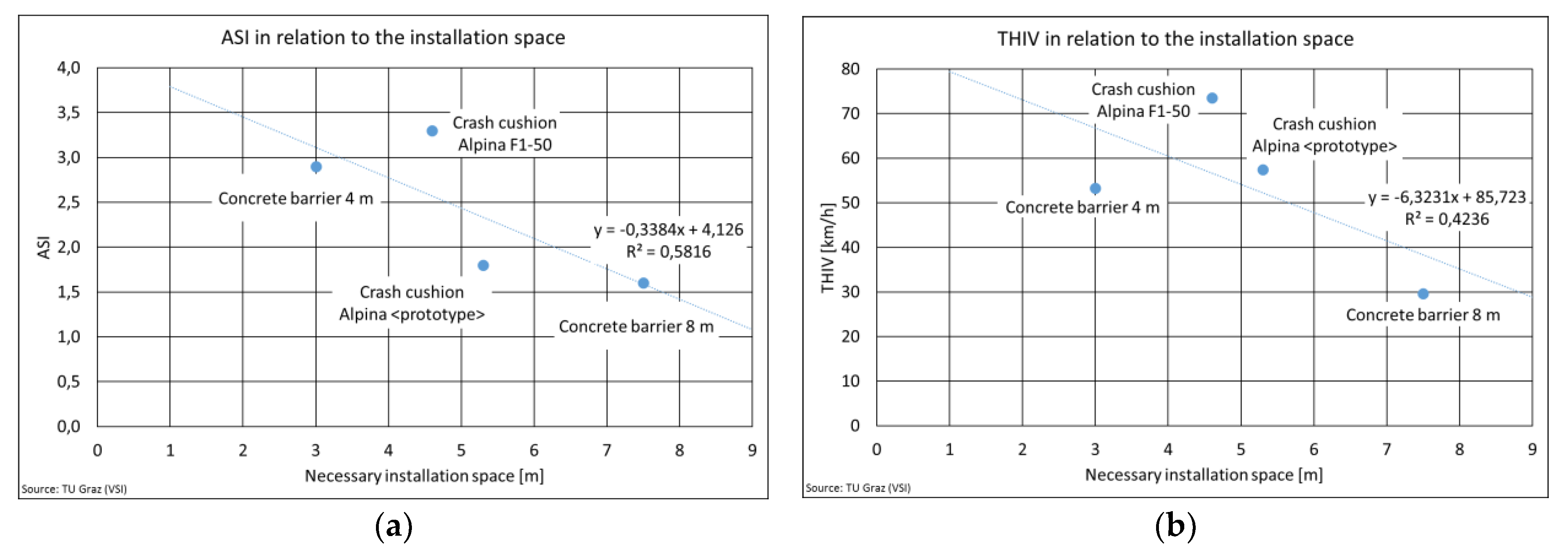
| ASI (Limit for severity level “B”: 1.4) | 2.9 | 1.6 | 3.3 | 1.8 |
| THIV (Limit a: 33 km/h for safety barriers and b: 44 km/h for crash cushions) | 53 | 30 | 74 | 57 |
| Secondary impact | Vehicle lifts up and impacts the end-wall of tunnel lay-by | Vehicle lifts up | No secondary impact | No secondary impact |
| Post crash kinematics | Vehicle rotates and is redirected into the road lane and impacts left tunnel wall | No vehicle rotation but is redirected into the road lane and impacts left tunnel wall | Vehicle moved backwards and was rotating around the vertical axis | Vehicle moved backwards and was rotating around the vertical axis |
| Test vehicle behavior after the impact | Uncontrolled | Uncontrolled | Yawing | Yawing |
| Test vehicle deformation | Intrusions | No intrusions | Intrusions | No intrusions |
| MAIS 2+ | MAIS 3+ | ||||
|---|---|---|---|---|---|
| ASI | Unbelted | Belted | Unbelted | Belted | |
| Unprotected wall [2] | 3.7 | 100% | 98% | 100% | 85% |
| Concrete barrier 4 m | 2.9 | 99% | 91% | 97% | 60% |
| Concrete barrier 8 m | 1.8 | 84% | 56% | 63% | 21% |
| Crash cushion Alpina F1-50 | 3.3 | 100% | 96% | 99% | 75% |
| Crash cushion Alpina <prototype> | 1.6 | 75% | 46% | 48% | 15% |
| MAIS 2+ | MAIS 3+ | ||||
|---|---|---|---|---|---|
| THIV | Unbelted | Belted | UNBELTED | belted | |
| Unprotected wall [2] | 56 km/h | 97% | 73% | 99% | 38% |
| Concrete barrier 4 m | 53 km/h | 96% | 69% | 97% | 32% |
| Concrete barrier 8 m | 30 km/h | 19% | 18% | 1% | 5% |
| Crash cushion Alpina F1-50 | 74 km/h | 100% | 94% | 100% | 78% |
| Crash cushion Alpina <prototype> | 57 km/h | 98% | 77% | 99% | 42% |
Publisher’s Note: MDPI stays neutral with regard to jurisdictional claims in published maps and institutional affiliations. |
© 2021 by the authors. Licensee MDPI, Basel, Switzerland. This article is an open access article distributed under the terms and conditions of the Creative Commons Attribution (CC BY) license (https://creativecommons.org/licenses/by/4.0/).
Share and Cite
Tomasch, E.; Heindl, S.F.; Gstrein, G.; Sinz, W.; Steffan, H. Assessment of the Effectiveness of Different Safety Measures at Tunnel Lay-Bys and Portals to Protect Occupants in Passenger Cars. Infrastructures 2021, 6, 81. https://0-doi-org.brum.beds.ac.uk/10.3390/infrastructures6060081
Tomasch E, Heindl SF, Gstrein G, Sinz W, Steffan H. Assessment of the Effectiveness of Different Safety Measures at Tunnel Lay-Bys and Portals to Protect Occupants in Passenger Cars. Infrastructures. 2021; 6(6):81. https://0-doi-org.brum.beds.ac.uk/10.3390/infrastructures6060081
Chicago/Turabian StyleTomasch, Ernst, Simon Franz Heindl, Gregor Gstrein, Wolfgang Sinz, and Hermann Steffan. 2021. "Assessment of the Effectiveness of Different Safety Measures at Tunnel Lay-Bys and Portals to Protect Occupants in Passenger Cars" Infrastructures 6, no. 6: 81. https://0-doi-org.brum.beds.ac.uk/10.3390/infrastructures6060081