1. Introduction
Soil–steel composite bridges (SSCB), also called “steel culvert bridges,” gained a great deal of popularity during the late 1940s and 1950s mainly due to their low initial cost, rapid manufacture, simplified construction, geometrical adaptability, and aesthetics.
In general, culvert bridges provide the required load-bearing capacity through interaction between the flexible culvert structure (i.e., flexible shell) and the surrounding soil and gain strength over time as the backfill soil consolidates [
1,
2]. They have various applications and can function as pedestrian, highway, railway, and road bridges, as well as conduits for water and traffic. Culvert bridges are most applicable for short span bridges (as an alternative to common concrete slab frame bridges) and therefore can address a substantial portion of the bridge market needs [
3].
Despite advantages offered by SSCBs, they have a few drawbacks. The most common being corrosion of the steel as a consequence of the abrasion of the galvanized steel coating and insufficient or faulty drainage, which eventually leads to degradation and weakening of the structure [
4]. Formation of local voids from corrosion that jeopardize the structural stability, loss of load-carrying capacity, and degraded hydraulic performance are among frequently reported faults in SSCBs, especially those over water [
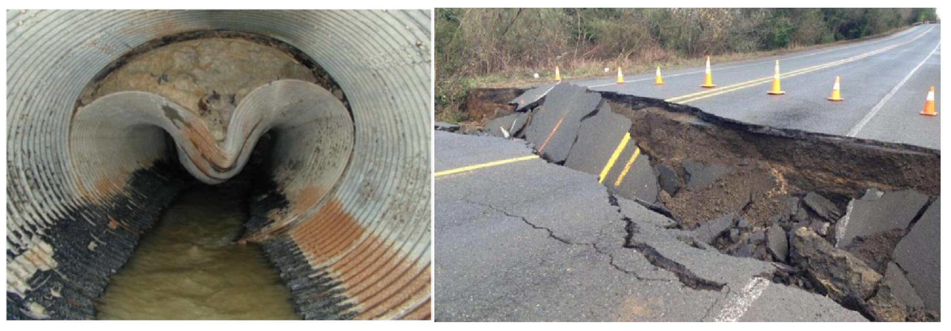
5]. Repair and protection against local and global corrosion is a common maintenance activity in SSCBs. Extreme cases of steel material loss can lead to large cross-sectional loss, causing backfill soil erosion and resulting in an imbalance and eventually both stability issues and collapse, as illustrated in
Figure 1.
To account for corrosion, guidelines usually suggest extra thickness of the steel plate so that the minimum required design thickness is assured throughout the service life of the structure [
6]. This approach is not a sustainable solution from the material consumption point of view and it has been shown that the minimum thickness cannot be guaranteed in practice [
7].
With adaptation of Eurocodes and increases in design loads in many European countries, compared to national norms, fatigue becomes a governing design parameter in many situations, especially large span SSCBs, necessitating a rather thick soil cover [
8]. The stress concentrations due to local corrosion around bolt holes would intensify the fatigue issue. Corrosion and fatigue problems are currently considered as two major drawbacks of SSCBs. Many culvert bridges around the world have deteriorated to the point that replacement or repair is warranted [
9].
Despite easy initial installation, replacement of a culvert bridge is a labor intensive, traffic intrusive, and costly intervention, and often involves full closure of the road and traffic detouring. According to [
10], a considerable portion of the cost in culvert replacement projects is related to indirect costs (i.e., user, traffic control, and safety measures).
Considering the drawbacks involved in traditional SSCBs, new solutions with improved durability and long-term performance would be necessary to maintain this kind of structure as competitive and reliable. This paper presents a feasibility study on using glass fiber-reinforced polymer (GFRP) composite materials as an alternative to steel for the construction of culvert bridges, while it concentrates on structural performance and economic viability. The hypothesis is that GFRP composites can offer more durable and less costly culvert structures to construct, operate, and maintain compared to traditional SSCBs. To examine the hypothesis, an existing SSCB was completely re-designed using GFRP and a comparative LCC analysis was conducted.
2. Fiber Reinforced Polymer (FRP) Composites in Construction and Their Applications in Culvert Bridges
In the contemporary multifaceted built environment, several new principles have emerged. Values such as aesthetics, energy efficiency, life-cycle costs, and low environmental and social impacts are among key design parameters in a sustainably built environment. Fiber-reinforced polymer (FRP) composites have emerged as a promising and sustainable alternative to traditional building materials in recent years [
13]. They consist of synthetic strengthening fibers such as glass and carbon embedded in a polymer matrix such as epoxy or polyester. FRPs offer superior mechanical and durability properties compared to traditional construction materials such as steel and concrete [
14,
15,
16]. Their low weight enables off-site manufacturing and on-site assembly, which is one of the main pillars of modern low-disturbance construction.
Application of FRP materials in construction is still in its infancy. The first commercial application in bridges (Aberfeldy footbridge in the UK) is approximately 30 years old. The complex material models and complicated design of FRP structures, relatively high material price, lack of design standards, and limited knowledge and experience among structural engineers are the most important hinderances towards the wide application of FRP composites in infrastructure.
Due to increasing interest in FRP composites in the construction industry, Work Group 4 “Fiber Reinforced Polymer Structures” entrusted to CEN/TC 250 (the Technical Committee appointed to draw up the structural Eurocodes) published the technical specifications document “Prospect for New Guidance in the Design of FRP (PrEN 19101)” [
17], which will be the foundation for the future Eurocode “Design of FRP Structures”. It is believed that the future Eurocode will eliminate many of the current impediments to implementing FRP composites in the construction sector [
18].
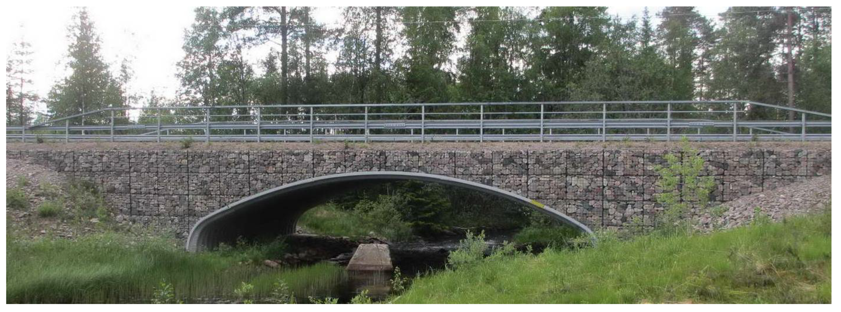
The application of FRP composites in culvert bridges is not unprecedented. The concept of a composite arch for short to medium span bridges, developed at the University of Maine [
19], takes advantage of lightweight, corrosion-resistant FRP composites in form-curved FRP tubes–filled with concrete–to act as the main load bearing element and has been used in the construction of several bridges in the US (see
Figure 2).
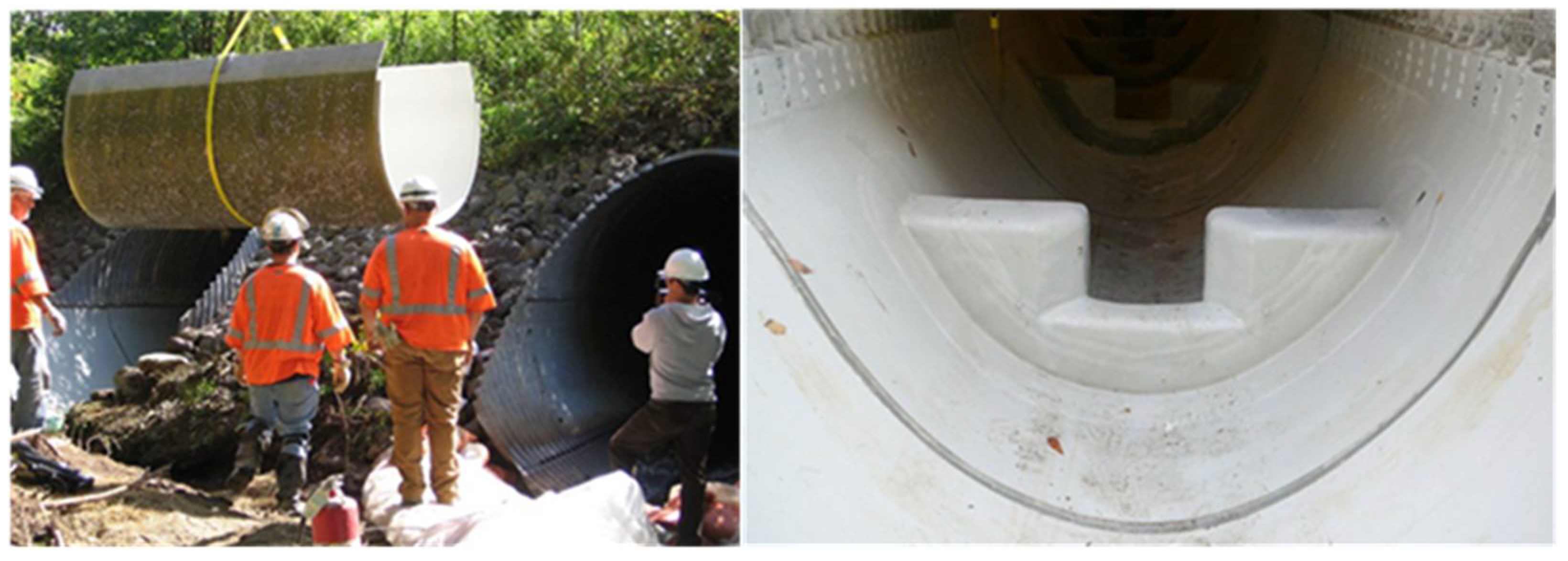
FRPs have also been successfully used for the refurbishment and life extension of existing culverts in recent years, especially those with corrosion problems.
Figure 3 shows an example of a steel culvert rehabilitated in the US, in which the integrity of the structure was restored using a partial lining of the invert with FRP composites. The corrugated metal plate in this bridge had eroded due to abrasion and corrosion, leading to the degradation and weakening of the culvert structure. The lining was installed in 5 days and has had an expected service life of 50 years.
Figure 4 depicts a full relining of a culvert using FRP composite materials.
3. Design of Steel–Soil Culvert Bridges
The flexible steel shell (normally made of corrugated steel plates in the shape of a pipe or an arch) buried under the soil is the main load bearing element of an SSCB. An SSCB gains its strength by the interaction between the steel shell and the surrounding soil. SSCBs require very thorough soil compaction, therefore a great deal of attention must be paid to the proper backfilling to obtain the desirable strength and prevent wash-outs and settlements [
23]. SSCBs are mainly classified as closed profiles (e.g., circular, elliptical, or pipe-arch) and open profiles, or so-called arch-types.
The concept of corrugated steel pipes was presented in the mid 1950s. The design was initially based on primitive diagrams and standard drawings, which included two types of conduits only: low-rise culverts and vertical ellipses. By then, the standard drawings were only applicable for structures with a span of up to 5 m. With increasing interest, more advanced and accurate design models were developed, allowing for the consideration of different soil materials, larger spans, and various cover heights. Extensive research was carried out between 1983 and 1990 at the Royal Institute of Technology in Sweden, of which 2000 resulted in the “Swedish Design Manual (SDM)” [
23]. According to the Swedish Bridge Standard [
24], culverts are commonly designed for a service life of 80 years; however, they are constantly exposed to an adverse environment, necessitating frequent inspection and maintenance services. The discussions with experts at the Swedish Transport Administration revealed that for culvert bridges in contact with water, a service life of 50 years is more realistic, which has been adopted in this study. An important parameter in the design of SSCBs is the soil height above the crown. The cover height is of significant importance when dealing with concentrated live loads. For small soil cover heights, live loads have more pronounced effects on the structural behavior of the culvert, introducing considerable bending moments in the shell structure as well as increasing the vulnerability to fatigue damage. For this reason, a minimum cover height of 0.6 m is adopted in the SDM [
23].
The culvert shape is mainly influenced by site conditions such as span and cover height, as well as hydraulics and flow capacity for river-passage culvert bridges. The selected configuration should result in a cost-effective design, accounting for durability.
4. The Case Study Bridge
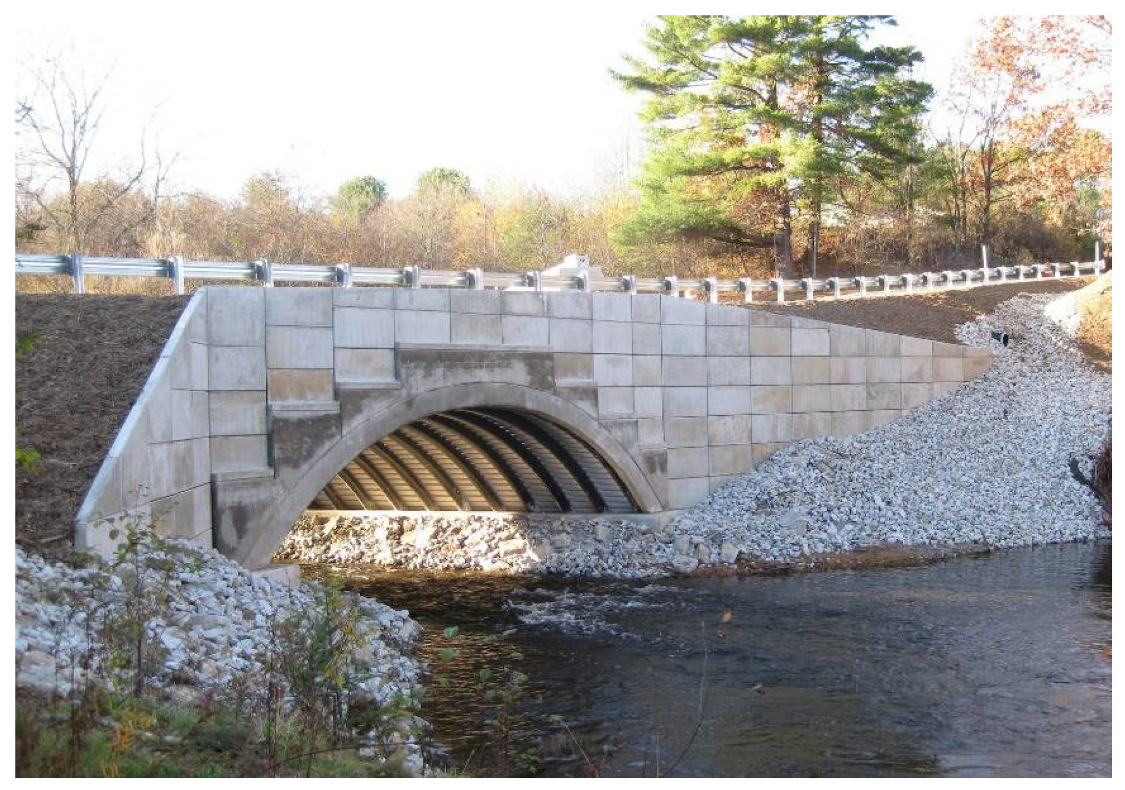
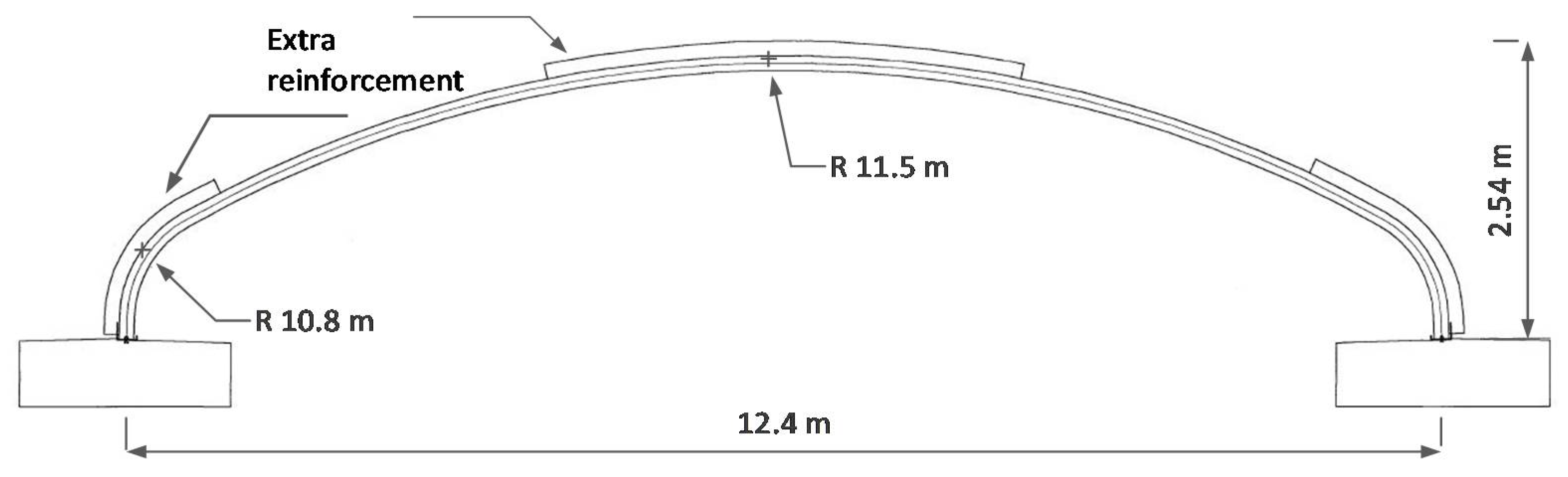
In 2008, an old bridge over Siktån river in Rörbäcksnäs in Sweden was replaced by a box culvert bridge; see
Figure 5. This bridge was selected as a case study because of its suitable dimensions and geometry for the purpose of this study. Moreover, necessary data regarding the cost of the project was available and obtained from the Swedish Transport Administration. The cross-sectional dimensions of the bridge are illustrated in
Figure 6. The selected culvert bridge carries the road traffic over a water passage. Important information about the bridge is listed in
Table 1.
4.1. Structural form of the FRP Culvert and the Design Process
Sandwich elements are known to deliver a considerably high stiffness/strength to weight ratio. They are very common in applications for which lightweight and material savings are key requirements. For this reason, the decision was made to use FRP sandwich elements to form the shell in the FRP culvert bridge concept. FRP sandwich elements often consist of two laminated face sheets (i.e., skins) and a core in between. The core can either be in solid form, e.g., foam material or honeycomb, or as simply discrete webs, also known as web cores. In this study, FRP sandwich elements with a foam core were used.
The extent of knowledge about the design of FRP structures is somewhat limited in terms of established material models and both calculation methods and checks. This means that the design and detailing of FRP structures are not as straightforward as for other structures built of conventional materials. This necessitates the application of advanced computational tools in the design process, e.g., the finite element method. In this study, commercial finite element software package Abaqus
® (version 6.11) was used to model the structure. The loads were calculated according to Eurocodes (EN 1990, EN 1991-2). To analyze the load effects, the approach adopted by the Swedish Design Manual [
23] for the design of culvert bridges was applied as explained in a following section. The design of the FRP structure and selection of partial factors were carried out according to provisions in PrEN 19101 [
17].
4.2. Loads and Partial Factors
Three load models including LM1 and LM2, according to Eurocode EN 1991-2, and an extra load model called “typfordon”, according to the Swedish standard “TRVK Bro 11” [
24], were considered in the design. The latter was considered as it was used in the design of the studied steel culvert bridge.
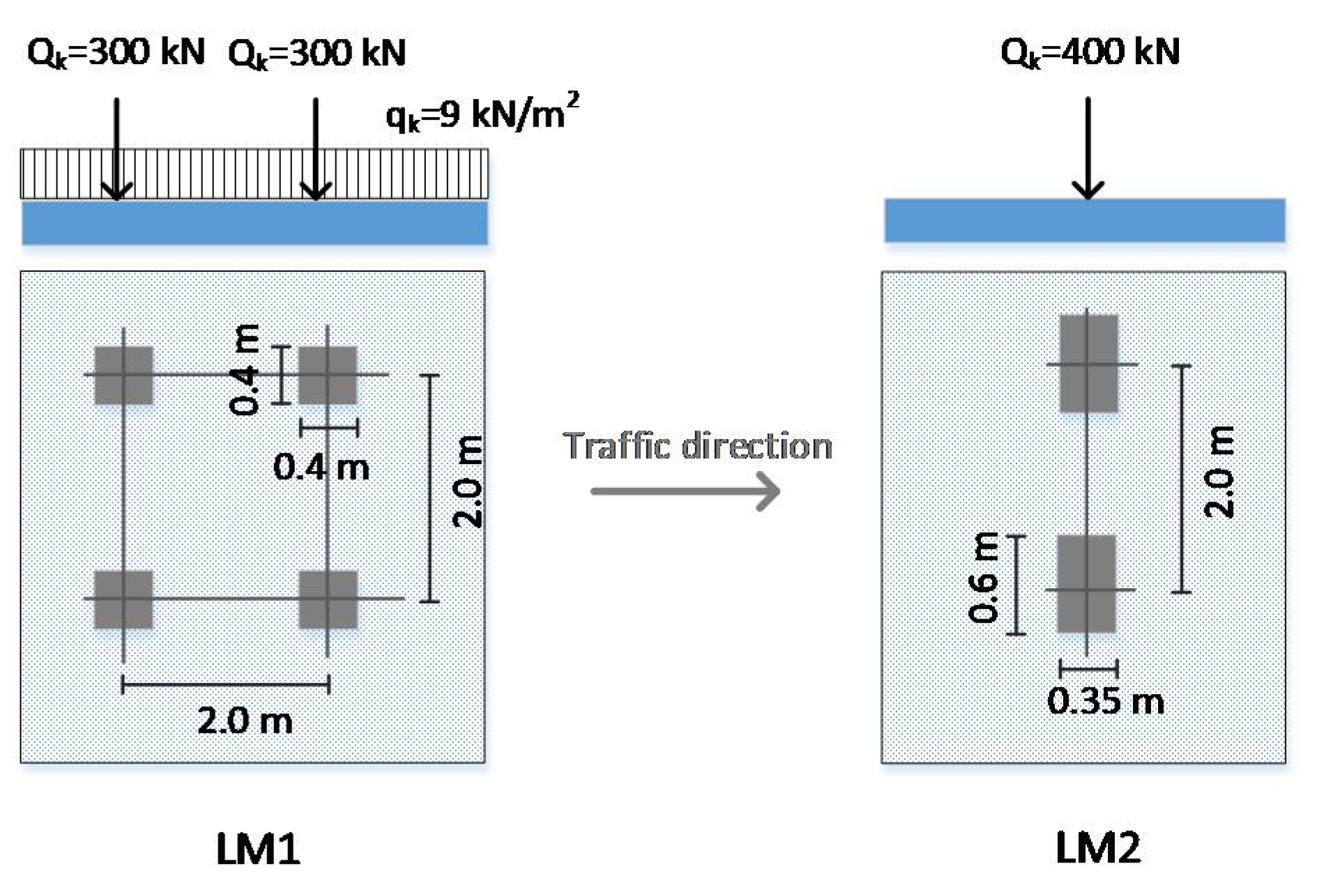
According to Eurocode 1, load model 1 (LM1) is a double-axel (i.e., tandem) that is applied on each lane together with a uniformly distributed load. The value adopted for the axel and uniform loads in Sweden are 300 kN and 9 kN/m
2, respectively. Load model 2 (LM2) is a single-axel with a load of 400 kN, which is applied anywhere on the carriageway. Load model “typfordon” represents realistic heavy traffic loads in Sweden. The model consists of 14 different trucks labeled from a–n and consists of two main loads, A and B, which have the values of 180 kN and 300 kN, respectively. The aforementioned loads represent heavy vehicles, while the lighter traffic loads are represented by a spread load “q”. The spread load is evenly distributed over the width of the carriageway and has values of either 5 kN/m or 0 kN/m. As this load model was not found to be governing in the design, it will not be discussed further here. Load models 1 and 2 are illustrated in
Figure 7.
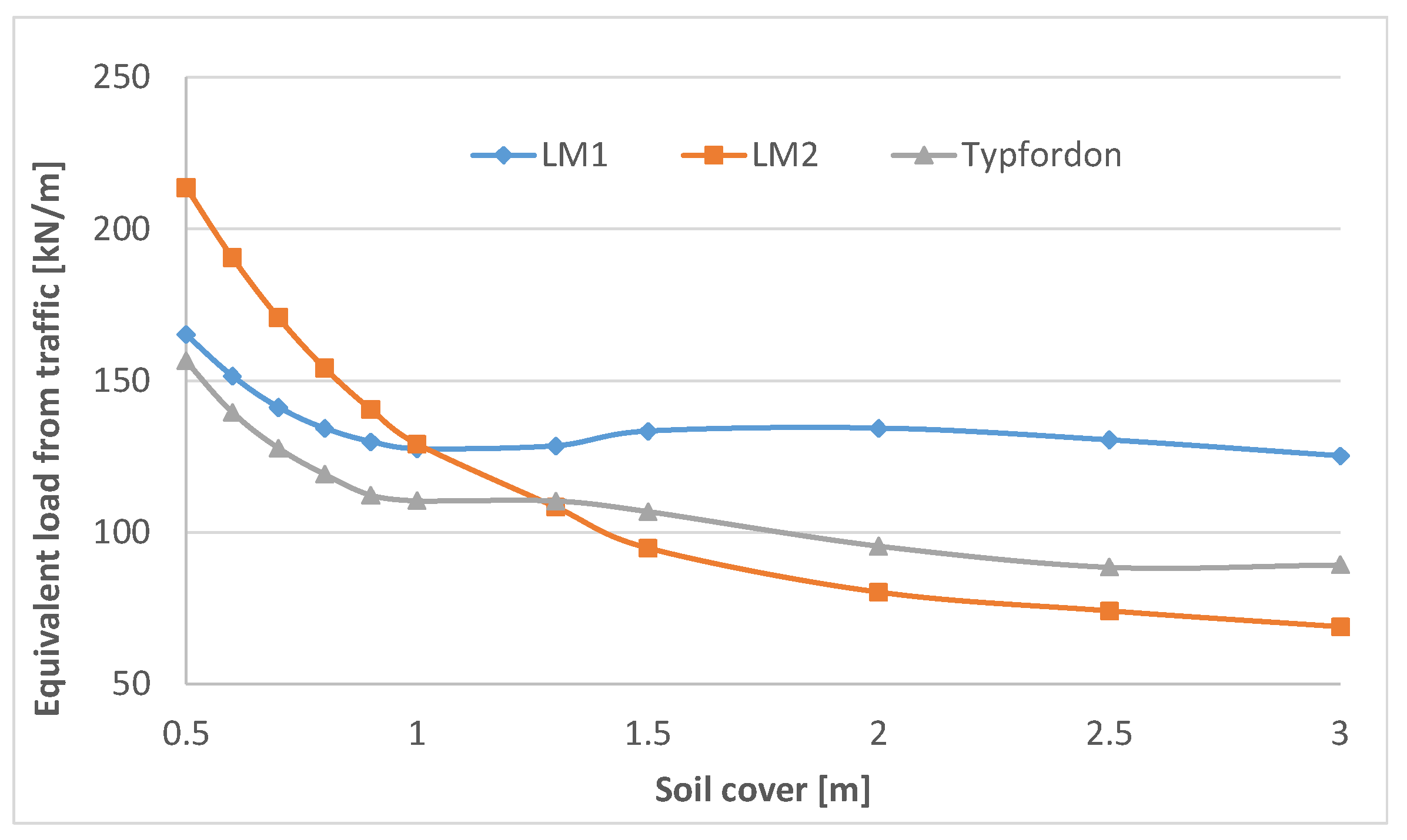
According to the SDM, the traffic load is converted into an equivalent line load based on Boussinesq’s semi-infinite body method. To obtain the corresponding value of the equivalent line loads for each load model, a numerical approach was used to find the most unfavorable load position at which the traffic load gives the highest vertical pressure on the culvert’s crown and this pressure was used to calculate the corresponding equivalent line load. Despite no restriction on the deflections in Eurocode 0 or the SDM in the serviceability limit state, a limit of L/400 was applied in the design of the FRP culvert in this study.
The equivalent line loads corresponding to the three load models are shown in
Figure 8. As can be seen, the traffic load resulting from LM2 is governing when the soil cover height is no more than 1 m, while LM1 is applied otherwise.
4.3. Material Properties
In this study, the E-glass-epoxy composite is chosen to manufacture the FRP laminates for the skins. The reason for this choice is the excellent mechanical properties of E-glass fiber with respect to its price and both the superior mechanical and durability characteristics of epoxy compared to other commercial thermoset resins. The E-glass fiber in this study has a modulus of elasticity equal to 70 GPa, a shear modulus of 30 GPa, and Poisson’s ratio of 0.22. The epoxy material has a modulus of elasticity equal to 3.3 GPa, a shear modulus of 1.3 GPa, and Poisson’s ratio of 0.34 [
25]. The laminate is unidirectional with a fiber volume fraction of 55%. In this study, PVC foam–Divinycell H80 supplied by DIAB
®–was chosen as the core material. As the ratio of the modulus of elasticity of the foam to FRP material is about 0.2%, the contribution of the foam material in the calculation of the sectional constants is neglected. To achieve the maximum stiffness and strength along the arch (i.e., parallel to the span of the bridge), the skins are considered to have a unidirectional structure (i.e., fibers in the 0 direction). The FRP shell was assumed to be manufactured using vacuum-assisted resin transfer molding (VARTM), which offers a great degree of flexibility in the manufacturing. Using VARTM, it is possible to create the FRP shell with varying thickness (i.e., following the moment diagram), while keeping the thickness of the skins constant. The characteristic material properties used in the design are summarized in
Table 2.
4.4. Verification by the Partial Factors Method and Initial Sizing
According to PrEN 19101, the verification of both elements and joints should be carried out in relation to both serviceability limit states (SLS) and ultimate limit states (ULS). For this purpose, a partial factors method should be used to verify that none of the limit states are violated during the design by assuring that the condition in Equation (1) is satisfied:
where
Ed and
Rd are the design values of the generic action and corresponding capacity (resistance and deformation) in the considered direction, within a generic limit state. In this study, the design values are obtained from characteristic values with appropriate partial factors suggested by PrEN 19101 and load combination factors adopted by the EN 1990 document. The design values for mechanical properties were determined using Equation (2):
in which
is a partial factor for the uncertainty in the resistance model;
is a partial factor accounting for unfavorable deviations of the material properties from their characteristic values;
represents the characteristic value of the material property; and
is the total conversion factor accounting for the effects of temperature and moisture.
The maximum temperature in the material was considered to be 25 °C according to the Swedish meteorological and hydrological institute (SMHI). According to the PrEN 19101, the conversion factors for temperature (
) for fiber-dominated (i.e., tensile strength in direction with high-fiber reinforcement) and matrix-dominated properties (i.e., compressive strength, interlaminar and in-plane shear strength) are calculated from Equations (3) and (4), respectively (PrEN 19101).
in which
Ts is the service temperature and
Tg is the glass transition temperature of the matrix, which was selected to be 60 °C (this value is the lower limit allowed by PrEN 19101).
For the core material, the thermal conversion factor is determined from Equation (5):
The FRP culvert, however, can be exposed to permanent contact with water (especially the inner side). PrEN 19101 explicitly emphasizes that composite structures should be prevented from continuous contact with moisture (i.e., exposure class 3) through a protective system (e.g., surface coating) to prevent extensive environmental degradation over the design service life. For this reason, the FRP shell is assumed to be covered by a gel coat layer on both sides and therefore no degradation of the material properties is considered. A moisture conversion factor () equal to 1.0 is therefore adopted in the calculations.
The overall conversion factor (
) for fiber and matrix-dominated properties of the FRP will be 0.96 and 0.9, respectively, and for the core material it will be 0.94. As for the effect of UV on the material, considering the structure is buried and not subjected to direct UV light, no reduction has been considered. According to PrEn 19101, the partial factor for material,
, is determined based on the coefficient of variation of the material property (
Vx). In this study
Vx is assumed to be 0.1, which results in
, and the partial factor for the resistance model,
, was determined to be 1.4 for sandwich panels. The partial factors together with relevant conversion factors were applied to
Table 2 to obtain the design values for the FRP material.
For the initial sizing of the FRP sandwich elements, the original soil–culvert interaction (SCI) method developed by [
27], adopted in the Swedish Design Manual [
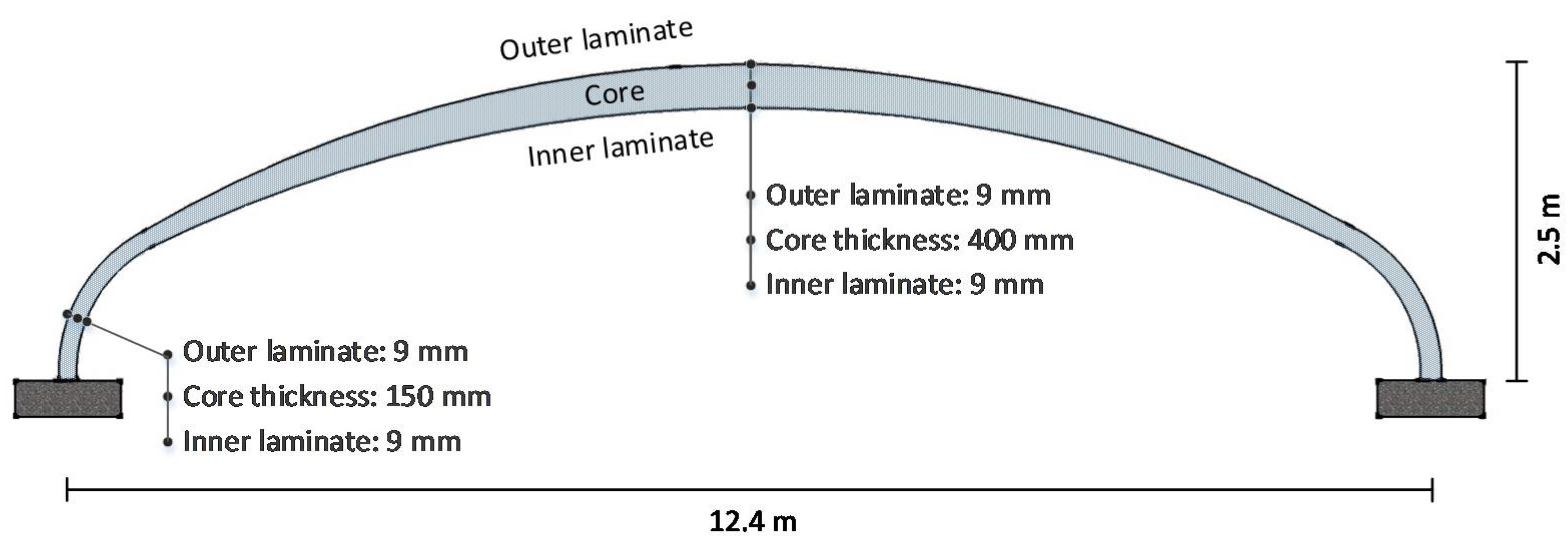
23], was used. The SCI is a two-dimensional model considering a strip of the culvert with unit width, neglecting the out-of-plane stiffness of the shell. This assumption yields acceptable results for the steel culvert as the stiffness of the corrugated steel plates perpendicular to the span direction is negligible. However, this is not the case in the FRP culvert as FRP sandwich elements, depending on the matrix and architecture of the skins, can display some stiffness in the transverse direction, leading to semi-two-way behavior. For this reason, the SCI method was used to initially size the sandwich element, with the final design verified through FE analysis at a later stage. The preliminary sizes of the sandwich elements are presented in
Table 3 and
Figure 9.
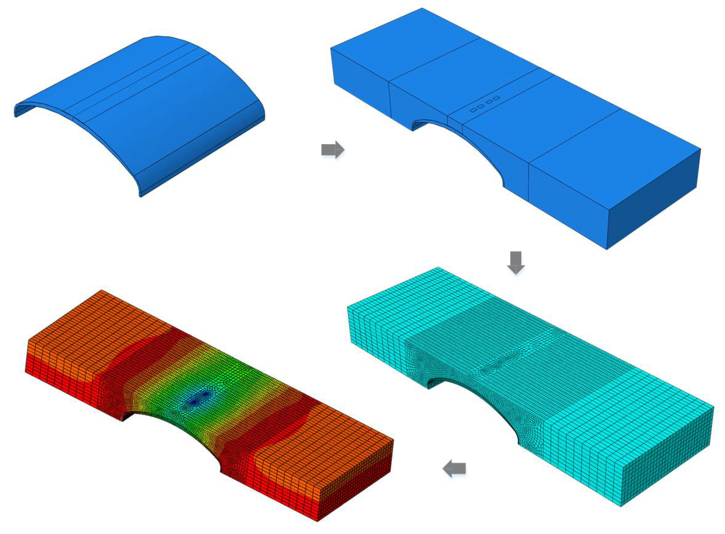
4.5. The Finite Element Model
To analyze and design the FRP culvert bridge in this study, a 3D FE model was developed in the commercial software Abaqus
® (version 6.11) as depicted in
Figure 10. The model accounted for the FRP material orthotropy with equivalent mechanical properties in relevant directions. To calculate the properties of the FRP laminates and cross-sectional stiffness of the sandwich elements, a calculation sheet using Mathcad
® software was developed and used, the details of which can be found in [
28].
The interaction between the soil and FRP shell for more rigorous analysis and design of the capacity of the FRP shell in the ultimate limit state (ULS) and deflections in the serviceability limit state (SLS) was taken into account.
To model the FRP laminates, namely the core material and soil, eight-node linear solid elements with reduced integration (C3D8R) were used. Linear-elastic properties were adopted for all three materials. To assure converged results, a mesh sensitivity study was conducted, based on which the optimum size of elements was chosen. The approximate size of the soil elements was set to 200 mm over the span of the culvert and was gradually increased to 900 mm. Three elements through the thickness of the FRP skins were introduced (size of approximately 3 mm). Four elements were placed through the thickness of the core, with the largest being 100 mm at the crown of the culvert.
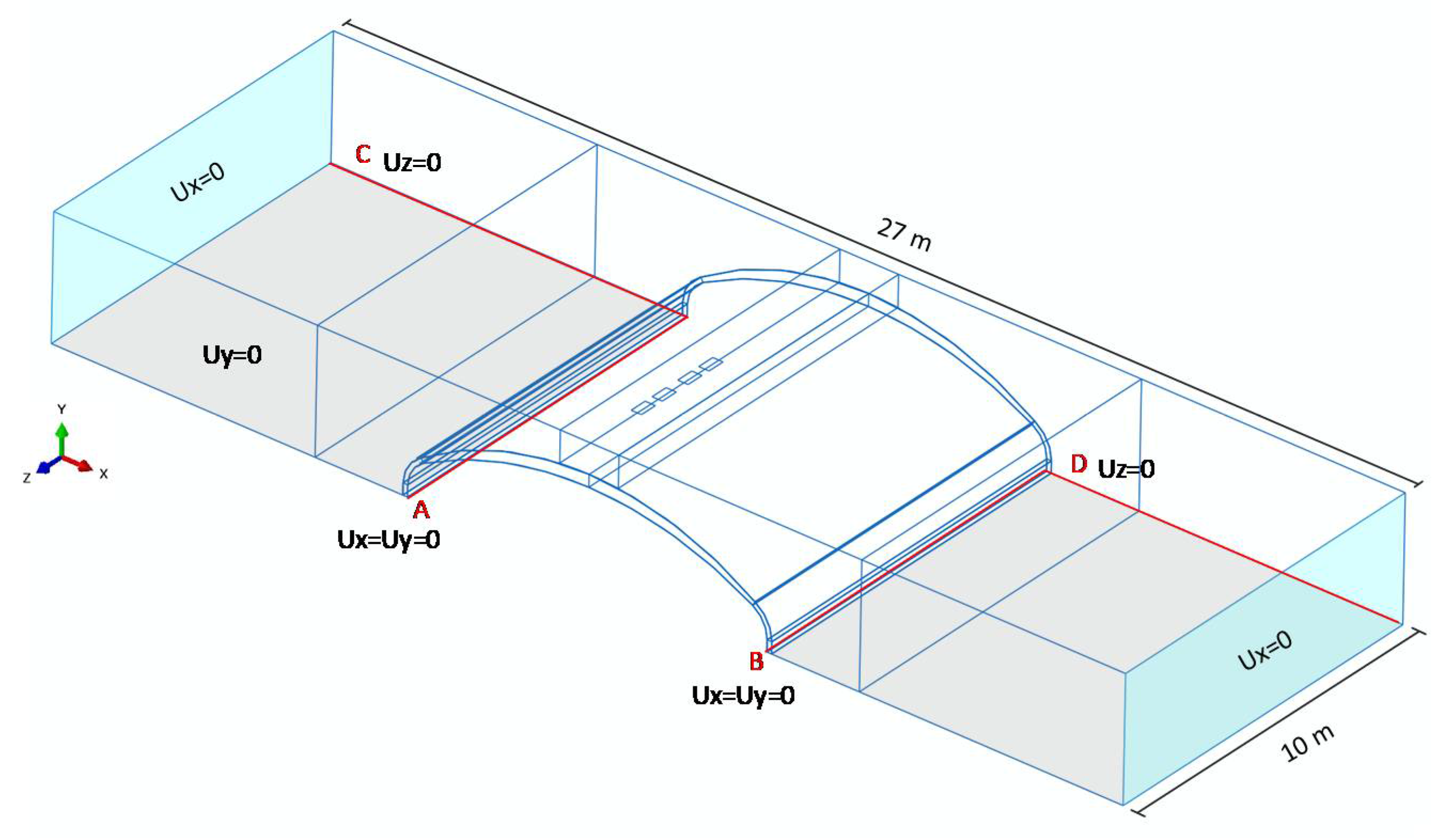
The boundary conditions considered in the model are illustrated in
Figure 11 (all other degrees of freedom are considered to be free). The FRP shell is supposed to be resting on concrete foundations (lines A and B), free to rotate about the Z axis.
The interaction of the soil and FRP shell was simplified and defined as frictionless hard-contact in the model. Neglecting friction is justified due to the presence of a gel coat layer on the outer surface of the FRP. The load was applied as a pressure on partitioned areas according to the size of the tire contact area, as defined in load models in Eurocode 1, and linear-elastic analysis was adopted.
The results of the FE analysis revealed that the deflection in the serviceability limit state is the governing design parameter. The maximum deflection under sustained load from the soil and transient traffic load was determined to be 27 mm (compared to a limiting value of 31 mm), giving a utilization ratio of 87%. The maximum compressive and tensile stress at the ultimate limit state at the crown were 21 and 8 MPa, equivalent to a 12% and 3% utilization ratio, respectively. It should be mentioned that checks such as the creep in the FRP material, the shear and compression capacity of the foam core in the sandwich elements, and the interface strength between the skins and the foam core were neglected in this study and need further investigations in the future.
Furthermore, detailed checks, such as controls for stability of the FRP face sheets due to buckling, should be investigated and, where necessary, have either the variable thickness adjusted or intermediate stiffeners added. However, it is felt that due to the very low strength utilization rate in compression, any changes to the cross-section would be relatively minor.
5. Life-Cycle Cost Analysis (LCCA) of the Case Study Bridge
In general, LCCA serves as a valuable tool for decision-making during bridge management processes. For culvert bridges in particular, LCCA is helpful to investigate potential savings as the long-term costs from maintenance and repair activities of conventional steel culverts contribute to a significant portion of the total life-cycle cost [
29]. The life-cycle cost can be categorized into agency costs, user costs, and social costs [
30], which take place in distinct phases. Different life-cycle phases of a bridge project in general include: (1) construction, (2) operation and maintenance (O&M), and (3) end of life. A schematic of different costs is illustrated in
Figure 12.
In the LCC analysis of the case study bridge, both the agency cost and user cost are considered from the investment phase, through the operation and maintenance phase, and to the end-of-life phase. The operation and maintenance phase extends from inauguration to demolition, which includes the activities applied to the bridge for inspection, operation, maintenance, repair, rehabilitation, and replacement [
29]. The social cost is not considered in this study.
5.1. The Net Present Value (NPV) and Equivalent Annual Cost (EAC) Method
Different costs take place at different times during the service life of a structure. Therefore, to be able to sum the costs and calculate the complete life-cycle cost, they should be converted to a value at a reference time. The net present value (NPV) method is the most common approach and is expressed by Equation (6) [
29]:
in which r is the discount rate, n is the considered year, L is the life span, and C
n is the cash flow in year n. In Sweden, a discount rate of 4% is recommended by the Swedish Transport Administration and is adopted in this study [
31].
The NPV method fits well when alternatives with the same life span are to be compared. For alternatives with different service life spans, the equivalent annual cost (EAC) method can be used instead. In finance, the EAC is the cost per year to own and operate an asset over its entire life span and is calculated using Equation (7) [
30]:
where A
t,r is the annuity factor. In this study, the design service life of the steel culvert bridge is set to 50 years, while a service life of 100 years is assumed for the FRP alternative [
32].
5.2. Annual and Net Saving
When the LCC results are expressed as EAC values, the alternative with a lower EAC is more economical. If this alternative is implemented, the annual saving can be presented as EAC
1 − EAC
2, where EAC
1 and EAC
2 are the equivalent annual cost of alternatives 1 and 2, respectively, assuming that alternative 2 is more economical. The concept of annual saving can be further developed into net saving (Equation (8)) regarding the life span of the alternative that is chosen to be implemented [
29].
where L
2 is the life span of alternative 2.
5.3. Agency Cost
5.3.1. Agency Cost in the Investment Phase
During the replacement of the old bridge over Siktån, a steel culvert bridge with a box profile was built in 2008. According to the project records registered in the Swedish Transport Administration Bridge and Tunnel Management System (BaTMan) [
5], the total investment cost for this bridge was 744,806 EUR. The culvert structure was fabricated with SuperCor
® steel plates supplied by Viacon
® at a cost of 59,600 EUR, which included the steel material and labor [
33], and accounted for 8% of the total project cost. Considering the majority of the cost of culvert bridges is associated with the earth work, it is more reasonable to evaluate the investment cost of an FRP culvert alternative based on that of the steel culvert project. The difference of investment cost would come from two sources: (1) the difference in the cost of the culvert itself and (2) the reduced thickness of the soil cover above the crown level in the FRP alternative. In the design of steel culverts, the thickness of the soil cover is advised to be not less than 1 m with respect to fatigue problems in the critical crown section [
23]. Due to the high fatigue strength of FRP materials, the soil cover thickness is reduced to 0.75 m in the FRP alternative.
Regarding these two major differences, the approximate investment cost of an FRP culvert bridge can be expressed by Equation (9).
where
INVFRP is the approximate investment cost of the FRP culvert bridge;
INVsteel is the investment cost of the steel culvert bridge, recorded in the BaTMan system;
Δ1 is the price difference between the FRP culvert and SuperCor® steel culvert; and
Δ2 is the price difference due to the reduced thickness of the soil cover above the FRP culvert.
The price of the considered FRP culvert structure in this case study was 38550 EUR as provided by DIAB
®, an FRP composite consultant and manufacturer in Sweden [
34].
5.3.2. Agency Cost in the Operation and Maintenance Phase (O&M)
- (A)
O&M cost of the steel culvert bridge
Quantifying the measures required during the operation and maintenance phase of a culvert bridge is an essential input for calculating O&M costs. The data regarding the selected bridge was obtained from the BaTMan [
5] and is summarized in
Table 4. Typical measures required to maintain the serviceability of steel culvert bridges during the O&M phase are listed in
Table 5 [
29,
35,
36].
During the operation and maintenance phase, the only difference between the FRP and steel alternatives would be the activities related to the shell structure itself and other cost items (e.g., pavement, railing, etc.) would be identical. For steel culverts, the corrosion of the inner surface cannot be avoided. Using shotcrete is a common measure to deal with this corrosion. Related activities before shotcrete, such as deviation of the water passage, and surface preparation result in additional costs. However, no action would be needed for the FRP alternative in this respect. More detailed calculations in this regard can be found in [
28].
5.3.3. Agency Cost at the End-of-Service Life
The disposal cost estimation mainly covers two items:
The disposal cost of a culvert bridge in general. According to [
37] and [
38], the disposal cost of a bridge can be assumed to be approximately 10% of the investment cost. According to BaTMan [
5] (30 June 2015), the (approximate) unit price of constructing a culvert bridge is 1710 EUR/m
2. Thus, the first component that contributes to the disposal cost can be assumed as 171 EUR/m
2.
The disposal cost of different culvert structures is dependent on the specific material. The major difference between the steel and FRP alternatives is due to the different disposal costs of these two materials. The recycling of steel can provide a profit of 50 EUR/ton, while the FRP material is supposed to be sent to a recycling plant, which costs 110 EUR/ton [
32]. The detailed calculation of disposal costs for both steel and FRP alternatives can be found in [
28].
5.4. User Cost
The user costs refer to the indirect cost for drivers and vehicles due to construction or maintenance work on the bridge site. The user costs in this study cover travel delay and vehicle operation but exclude crash costs in the construction zone. A cost of 34.7 EUR/h for trucks and 16.7 EUR/h for passenger cars were adopted in this study as suggested by [
30]. During the investment phase, the traffic was blocked, thus vehicles needed to take a detour. The duration of traffic disruption was assumed to be one month in this study and a detour length of 1650 m (compared to the original road length of 950 m) was determined. During the service life, the normal traffic flow would also be disrupted due to O&M activities. The following assumptions were made to calculate the user cost during the O&M phase:
ADT of 146 vehicles per day (including 7% heavy traffic);
the work zone length was assumed to be 200 m;
the speed of vehicles was reduced from 50 km/h to 40 km/h;
two workdays were required for activities including (1) the maintenance of pavement, surface finishes, and lining, and (2) shotcrete repair of corrugated steel sheets; and
one workday was required for activities including (1) the maintenance of parapets and railings, (2) railing repainting, and (3) railing replacement (if necessary).
5.5. Results of the LCC Analysis
The LCC results are expressed in terms of EAC in
Table 6.
5.6. Sensitivity Analysis
Even though the abovementioned conclusions are based on LCC analyses of a real case, uncertainty in the assumptions always exists. To add more credit to the LCC analysis, a sensitivity analysis was carried out to investigate the impact of variability in seven important parameters on the overall results. These parameters include:
the discount rate,
the ADT volume over the bridge,
the price of the FRP culvert structure;
the price of the steel culvert structure;
the expected life span of the FRP culvert bridge;
the extent of the shotcrete rehabilitation of the steel culvert bridge during its service life; and
the thickness of the soil cover over the FRP culvert structure.
The results are expressed and compared in EAC values if not specifically clarified.
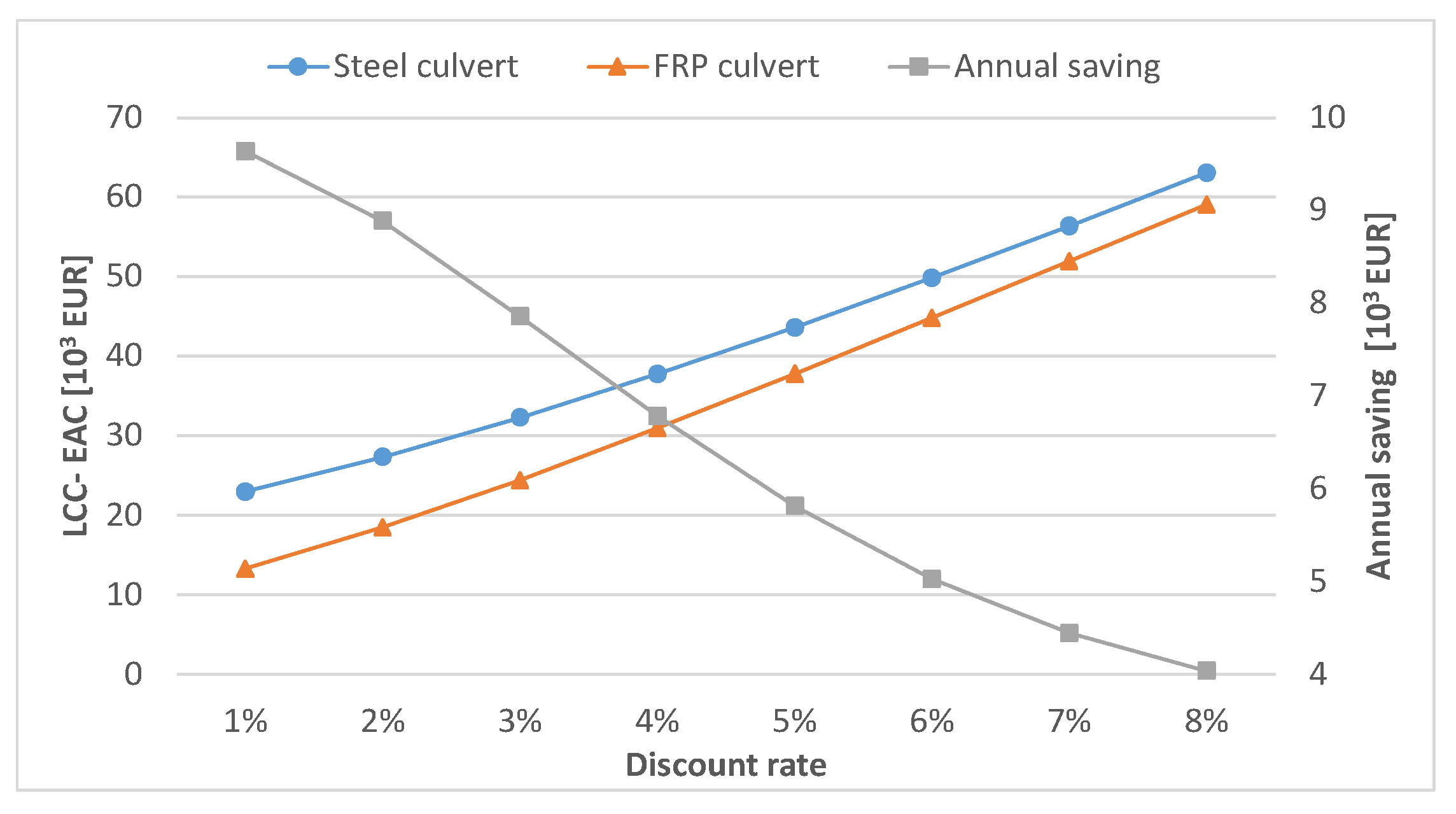
5.6.1. Discount Rate
The change of discount rate would greatly influence the life-cycle cost and the economy of the project. The discount rate investigated here covers a range from 1 to 8% [
31,
38]. In the primary LCC calculations, the discount rate was set to 4% as recommended by the Swedish Transport Administration [
31]. The result of the sensitivity analysis (see
Figure 13) shows that the uncertainty in the discount rate does influence the cost efficiency of the FRP alternative. It is observed that the higher discount rate would result in lower cost benefits of the FRP alternative. However, the FRP alternative still results in lower LCC compared to the steel culvert bridge over the investigated range.
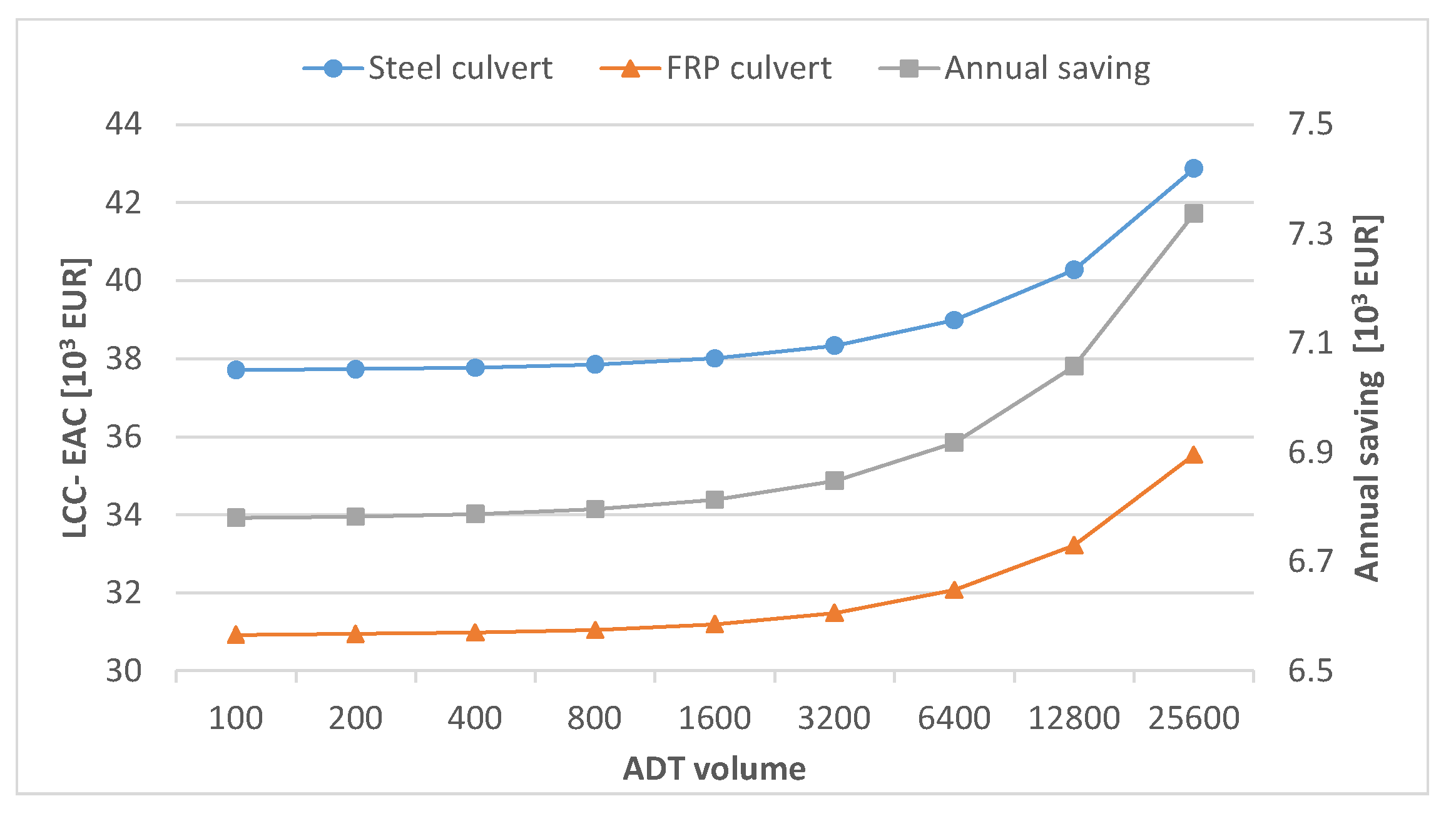
5.6.2. ADT Volume
The ADT volume over the case study bridge was 146 vehicles per day. However, in roads connected to densely populated areas, the ADT volume can attain much larger numbers. In this study, the LCC has been investigated for ADTs of up to 20,000 vehicles as presented in
Figure 14.
It is seen from this figure that the annual savings does not significantly change with respect to ADT for small traffic volumes. However, as traffic volume increases, the FRP alternative delivers higher annual savings, which is mainly attributed to lower maintenance needs of the FRP culvert and thus less user costs. It can be concluded that the uncertainty in the ADT volume does not influence the cost competitiveness of the FRP alternative and the project’s economy enhances in more trafficked roads.
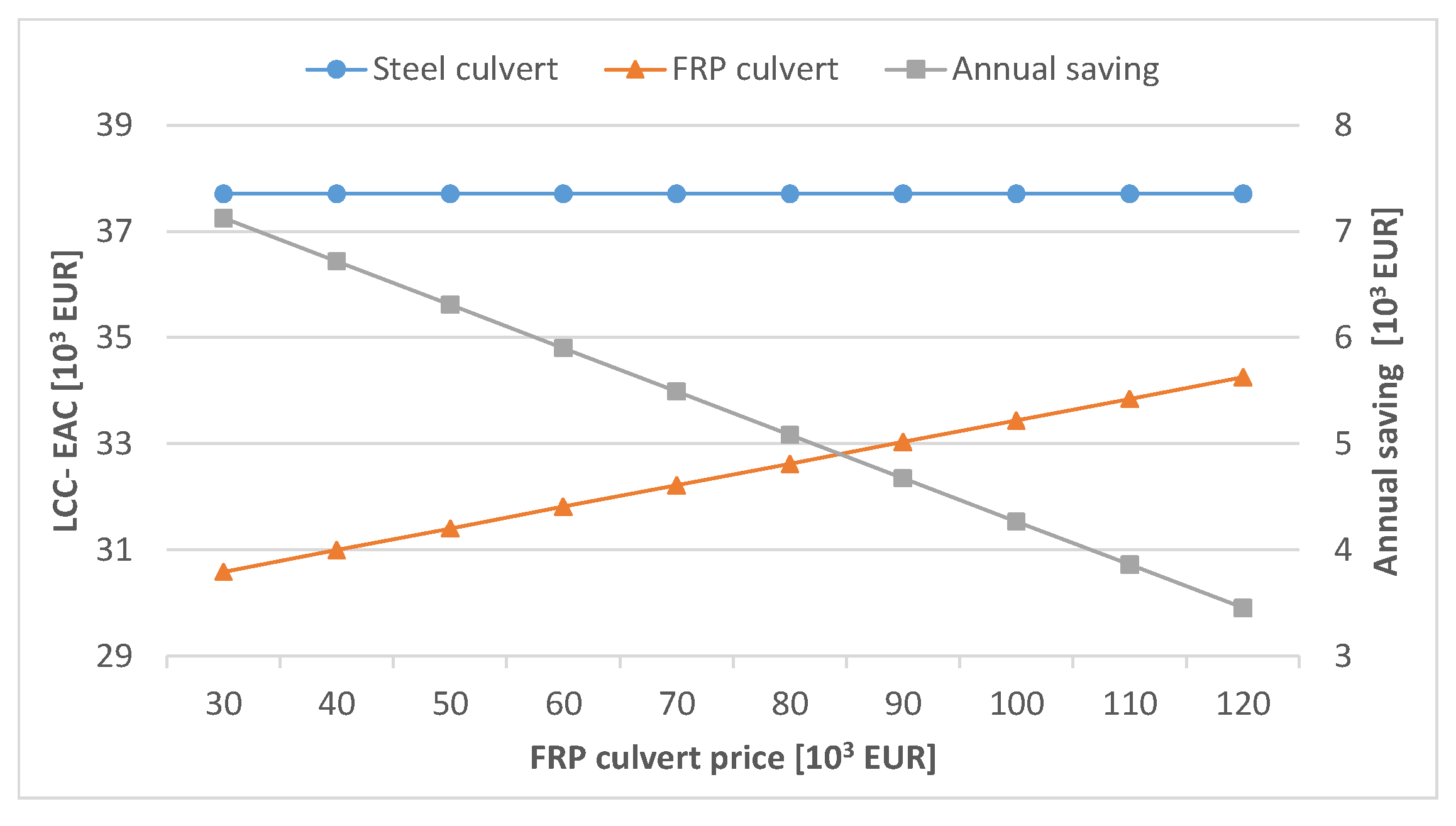
5.6.3. Price of the FRP Culvert Structure
Figure 15 shows the impact of the FRP shell structure price on the LCC. A price range from 30,000 EUR to 120,000 EUR has been considered. It is observed that the FRP alternative will be more price competitive over the considered range. The FRP alternative maintains its competitiveness up to a price of 205,000 EUR. Finding less expensive methods to produce the FRP shell would improve the price competitiveness of the FRP alternative. Furthermore, the decreasing trend in the global price of FRP supports the idea that the FRP option in this study will be more economical in the future.
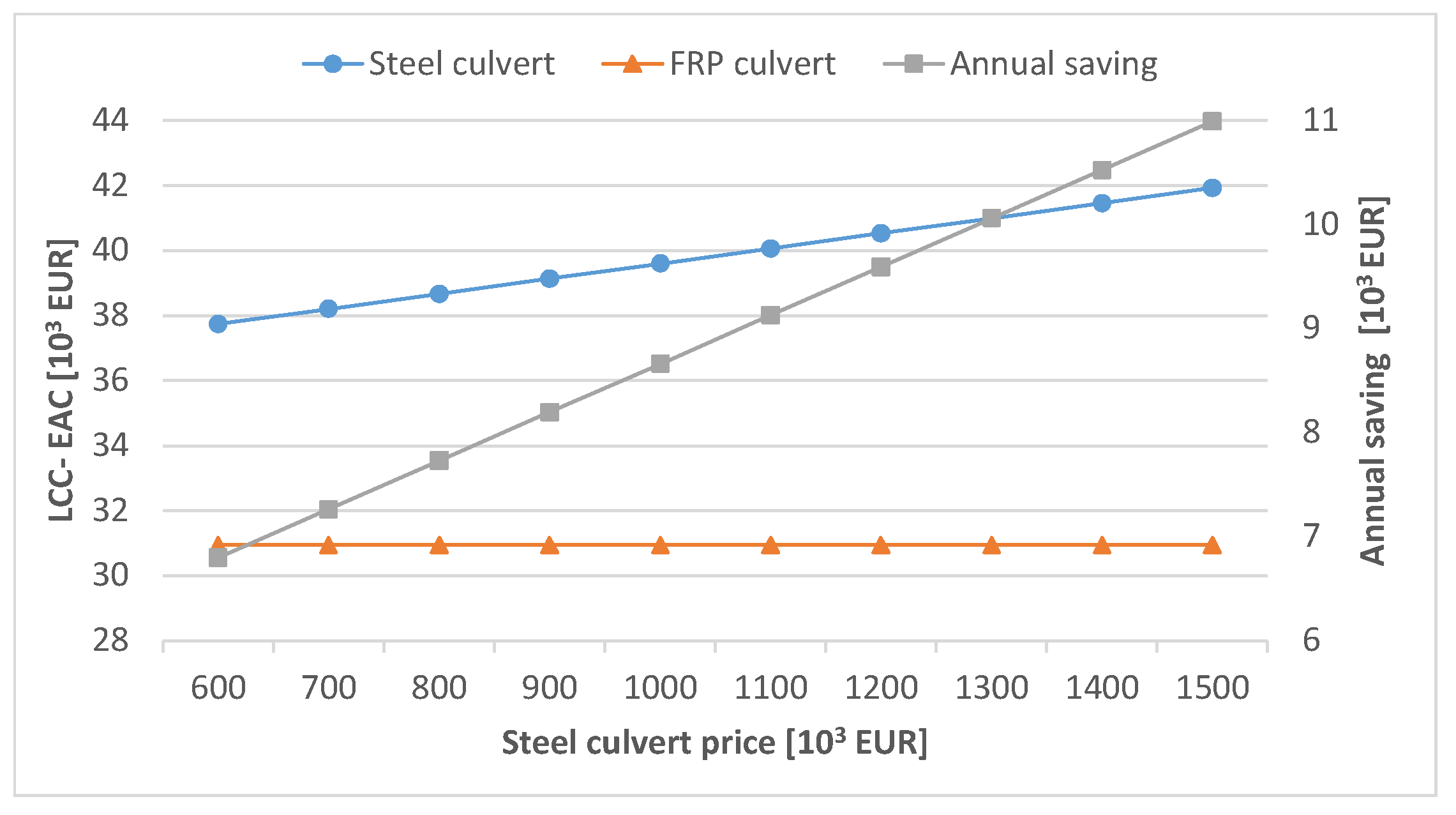
5.6.4. Price of the Steel Culvert Structure
The price of steel has increased significantly in the past few years and it is worth to study this parameter as a variable in the LCCA.
Figure 16 shows that the impact of the price of the steel structure on the LCC. As expected, it can be observed that the increase in the steel culvert price reduces its price competitiveness and considerable savings can be gained by choosing FRP over steel at higher steel prices.
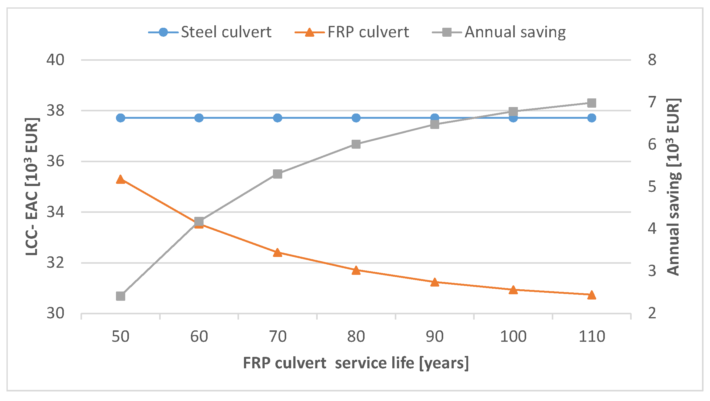
5.6.5. Design Life Span of the FRP Culvert Bridge
There is a good deal of experience with the behavior and service life of steel culverts. The design service life of the steel culvert bridge in this study was set to 50 years. However, determining the service life of the FRP culvert is associated with many uncertainties. For this reason, the service life of the FRP culvert was studied as a variable covering a range of 50 to 110 years.
Figure 17 demonstrates that the FRP alternative offers a lower LCC for the considered range. In fact, the FRP alternative loses its price competitiveness only if its service life is shorter than 42 years. From a technical point of view, a minimum life span of 80 years is reasonable for FRP structures, while a life span of 100 years can be achieved in the presence of proper inspection and appropriate maintenance.
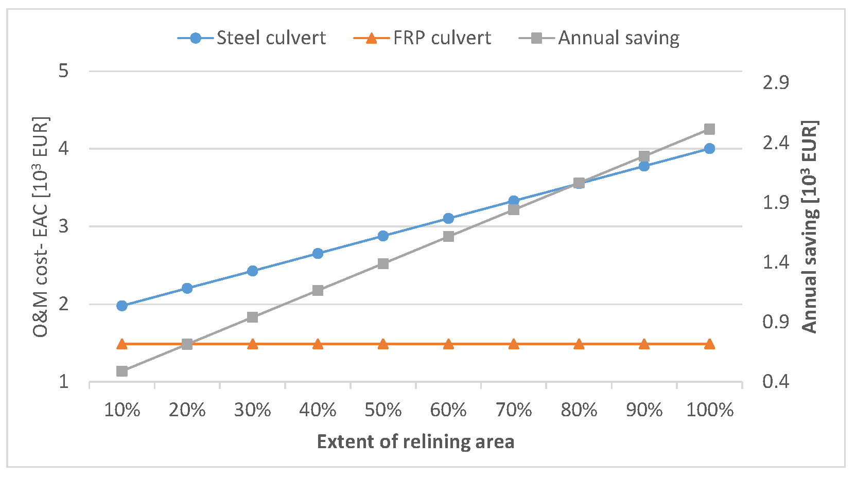
5.6.6. Extent of the Shotcrete Rehabilitation Applied to the Steel Culvert
As a measure to deal with corrosion problems in steel culverts, applying shotcrete to repair corroded steel plates is a common practice during the service life. The extent of area that requires a shotcrete measure after a 30-year-operation period depends on its degree of corrosion. In the LCC calculation, the target quantity is assumed to be 50% of the total culvert inner surface area. This is a reasonable assumption as usually the lower half of the culvert, which is in contact with water, suffers from corrosion problems. Due to the relatively high cost of shotcrete activity, the amount of corrosion area would directly influence the O&M cost during the service life.
Figure 18 shows that, as expected when the corrugated surface area is larger, the LCC of the steel alternative becomes larger compared to that of the FRP alternative.
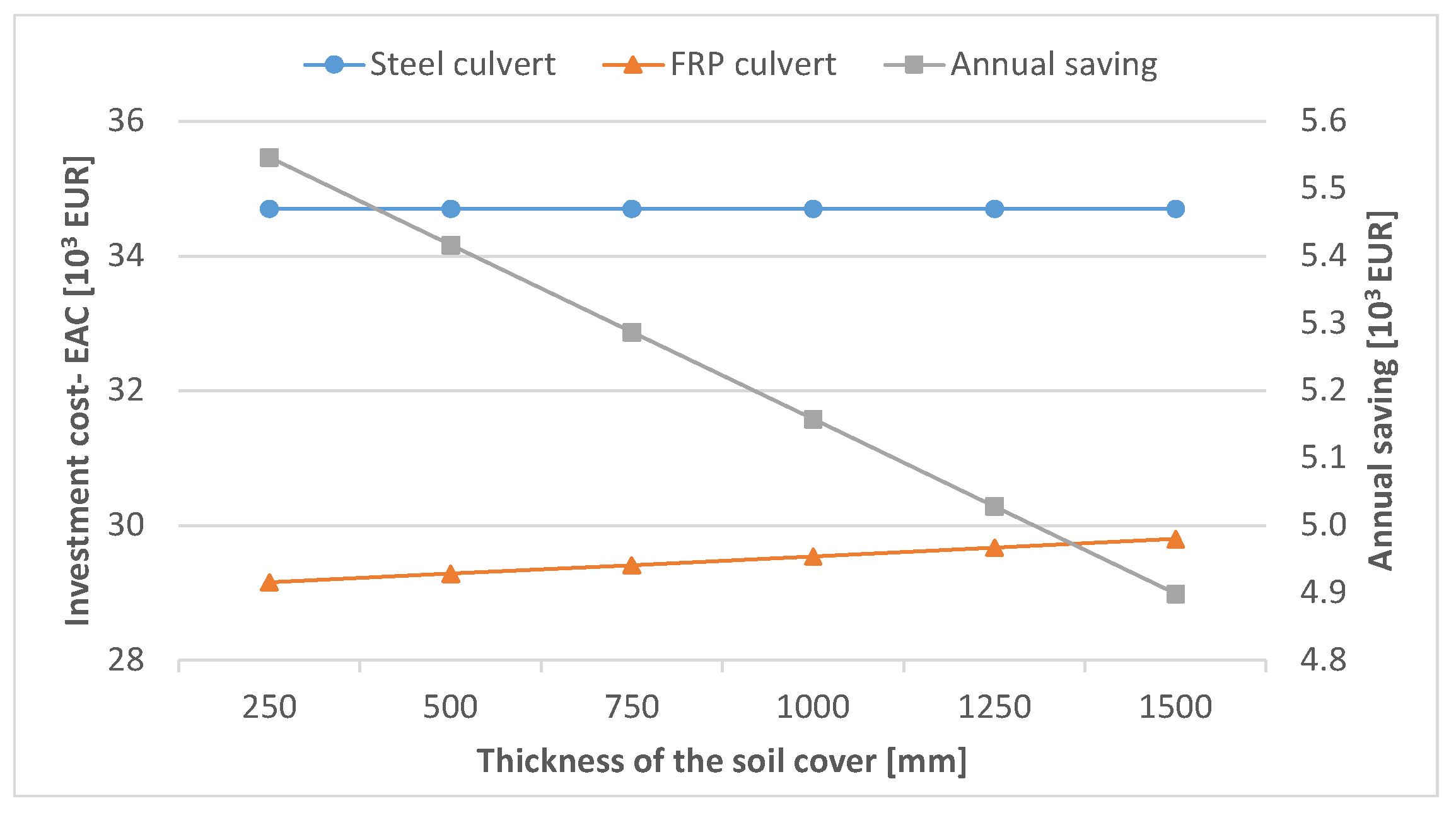
5.6.7. Thickness of the Soil Cover over the FRP Culvert
As fatigue is not an issue in the FRP culvert alternative, the thickness of the soil cover over the FRP culvert crown can be reduced. The reduction in soil cover thickness leads to less earthwork and reduced cost during construction.
Figure 19 shows that the thinner soil cover results in better cost efficiency of the FRP alternative. The sensitivity study shows that increasing the soil cover thickness on the FRP alternative from 1000 mm to 1500 mm would reduce the savings by 5% with regard to the investment cost. It is important to mention the fact that increasing the soil cover thickness will result in the better performance of the culvert structure under the applied loads; therefore, to find the optimum soil thickness, the design of the culvert shell needs to be considered at the same time.
6. Discussion and Conclusions
A feasibility study was carried out on the application of FRP composite materials for the construction of culvert bridges from both a structural and economic point of view. The structural feasibility was demonstrated through the redesign of an already existing steel culvert bridge using FRP sandwich elements. The LCC analysis of the case study bridge demonstrated the cost efficiency of the FRP alternative due to the lower initial and maintenance costs, as well as the longer service life compared to the steel alternative. A parametric study was also carried out to investigate the sensitivity of the results to variations of different design parameters. It proved that under many circumstances, the FRP alternative will be more cost-efficient compared to the steel culvert.
One of the advantages in using FRP in culvert structures is the inherent fatigue strength of the material. In large span steel culverts (i.e., above 10 m), fatigue is the governing design factor with respect to elevated fatigue loads in the Eurocode 1, which necessitates rather thick soil covers (i.e., above 1 m). This is not, however, the case for FRP culverts. This allows for thinner soil layers, which need less costly earth work.
Steel culverts also face more challenges in the ultimate limit state for large spans, for which the reinforcement of crown and corners is often necessary. The advantage in using FRP sandwich elements concerns the ability to create sections with variable heights, which follows the moment diagram. This way, sandwich elements can be constructed with uniform skin thickness.
It is concluded that large span culverts located on water can be considered as a target segment for the application of FRP composite culverts. However, this conclusion is associated with several limitations in this study.
In the design of the FRP culvert, detailed checks, such as controls for the stability of skins due to buckling and the creep in the FRP under sustained loads, have not been considered and need to be investigated in future studies.
No maintenance costs have been specifically considered for the FRP shell. This was mainly due to prior knowledge about the outstanding performance of FRPs in marine applications and the existing experience from offshore structures. Further investigations about the long-term performance of FRPs in novel applications, such as the one considered in this study, will be needed.
No material degradation due to moisture was considered. This was mainly due to the presence of a protective layer (i.e., gel coat) on both sides of the FRP shell. According to PrEN 19101, the effectiveness and environmental durability of protective systems should be evaluated by experimental tests and therefore precautions are recommended in this regard.
Despite better structural performance and cost efficiency for FRP alternatives, the manufacturing and assembly, including transportation and joining, remain a challenge and need further investigations.
Furthermore, recycling thermoset FRP materials remains a challenge. To close the loop for these materials in a circular economy, thermoplastic matrices need to be considered while preserving product functionality, material properties, and economic value, which necessitates more research in the future.
In order to improve the structural performance in the FRP alternative in this study, the following investigations are suggested.
Optimization of the section and use of stiffer fibers such as carbon in combination with glass fibers to form a stiffer, yet strong, FRP skin. The cross-sectional profile of the FRP shell can also be subjected to optimization to take advantage of the geometrical stiffness.
Use FE modeling to design the fiber orientation and lay-up architecture in the FRP laminates to achieve better material utilization.
Enhance the accuracy of the FE model. In this study, equivalent mechanical properties were used for material modeling. To study the behavior in more detail, the FRP material can be modelled as orthotropic laminates considering the correct stack up.
This study should be regarded as a first step for the novel application of FRP composites in culvert bridges. The results and conclusions are limited to the specific studied bridge and certain assumptions, and therefore they should not be generalized before detailed studies are completed.
Author Contributions
Conceptualization, R.H. and J.Y.; methodology, J.Y. and R.H.; software, J.Y.; validation, R.H. and J.Y.; formal analysis, C.D.E.; investigation, J.Y. and R.H.; data curation, R.H. and J.Y.; writing—original draft preparation, R.H.; writing—review and editing, M.G., C.D.E. and J.V.; visualization, R.H.; supervision, R.H.; project administration, R.H.; funding acquisition, R.H. All authors have read and agreed to the published version of the manuscript.
Funding
This research study received funding from Chalmers Areas of Advance and the Swedish Transport Administration.
Institutional Review Board Statement
Not applicable.
Conflicts of Interest
The authors declare no conflict of interest. The funders had no role in the design of the study; in the collection, analyses, or interpretation of data; in the writing of the manuscript, or in the decision to publish the results.
References
- Beben, D. Corrugated steel plate culvert response to service train loads. J. Perform. Constr. Facil. 2014, 28, 376–390. [Google Scholar] [CrossRef]
- Sezen, H.; Yeau, K.Y.; Fox, P.J. In-situ load testing of corrugated steel pipe-arch culverts. J. Perform. Constr. Facil. 2008, 22, 245–252. [Google Scholar] [CrossRef]
- Safi, M.; Du, G.; Simonsson, P. Sustainable Bridge Procurement Considering Life Cycle Cost, Life Cycle Assessment and Aesthetics. In Proceedings of the 19th IABSE Congress, Stockholm, Sweden, 21–23 September 2016. [Google Scholar]
- Thompson, B. Culvert Rehabilitation & Invert Lining Using Fiber Reinforced Polymer (FRP) Composites. Report. 2010. Available online: https://rosap.ntl.bts.gov/view/dot/27112 (accessed on 1 June 2016).
- Swedish Bridge and Tunnel Management System (BaTMan). 2020. Available online: https://batman.trafikverket.se/externportal (accessed on 1 June 2016).
- Pettersson, L.; Sundquist, H. Design of Soil Steel Composite Bridges, TRITA-BKN, Report 112, 5th ed.; Royal Institute of Technology: Stockholm, Sweden, 2014; ISSN 1103-4289. Available online: https://www.diva-portal.org/smash/get/diva2:761594/FULLTEXT01.pdf (accessed on 1 June 2016).
- Thornton, C.I.; Robeson, M.D.; Girard, L.G.; Smith, B.A. Culvert Pipe Liner Guide and Specifications; Report No. FHWA-CFL/TD-05-003; Federal Highway: Administration, VA, USA, 2005. [Google Scholar]
- Haghani, R. Preliminary Study on Using FRP Materials in Culvert Road Bridges—Mechanical Behavior and Life-Cycle Cost Analysis; Chalmers University of Technology: Göteborg, Sweden, 2015; Available online: http://publications.lib.chalmers.se/records/fulltext/212911/212911.pdf (accessed on 1 June 2016).
- El-Taher, M. The Effect of Wall and Backfill Soil Deterioration on Corrugated Metal Culvert Stability. Ph.D. Thesis, Queen’s University, Kingston, ON, Canada, 2009. [Google Scholar]
- Perrin, J.; Jhaveri, C.S. The Economic Costs of Culvert Failures. In Proceedings of the TRB Annual Meeting, Washington, DC, USA, 11–15 January 2004; Available online: http://www.concretepipe.org/wp-content/uploads/2015/05/economiccosts.pdf (accessed on 1 June 2016).
- Federal Highway Administration (FHWA). Culvert Management Case Studies: Vermont, Oregon, Ohio and Los Angeles County. 2014. Available online: https://www.fhwa.dot.gov/asset/pubs/hif14008.pdf (accessed on 1 June 2016).
- KPIC. Available online: www.kpic.com (accessed on 1 June 2016).
- Mara, V.; Al-Emrani, M.; Haghani, R. A novel connection for fibre reinforced polymer bridge decks: Conceptual design and experimental investigation. Compos. Struct. 2014, 117, 83–97. [Google Scholar] [CrossRef] [Green Version]
- Heshmati, M.; Haghani, R.; Al-Emrani, M. Durability of CFRP/steel joints under cyclic wet-dry and freeze-thaw conditions. Compos. Part B Eng. 2017, 126, 211–226. [Google Scholar] [CrossRef]
- Mara, V.; Haghani, R. Review of FRP decks: Structural and in-service performance. Proc. Inst. Civ. Eng. Bridge Eng. 2015, 168, 308–329. [Google Scholar] [CrossRef]
- Heshmati, M.; Haghani, R.; Al-Emrani, M. Dependency of cohesive laws of a structural adhesive in Mode-I and Mode-II loading on moisture, freeze-thaw cycling, and their synergy. Mater. Des. 2017, 112, 433–447. [Google Scholar] [CrossRef] [Green Version]
- PrEN 19101, Design of Fibre-Polymer Composite Structures 2020. Available online: https://www.itke.uni-stuttgart.de/research/current-research-projects/fibre-reinforced-polymers/ (accessed on 1 June 2016).
- Mara, V.; Haghani, R.; Sagemo, A.; Storck, L.; Nilsson, D. Comparative study of different bridge concepts based on life-cycle cost analyses and life-cycle assessment. In Proceedings of the 4th Asia-Pacific Conference on FRP in Structures, APFIS, Melbourne, Australia, 11–13 December 2013. [Google Scholar]
- The University of Maine. Available online: www.composites.umaine.edu (accessed on 1 June 2016).
- Triandafilou, L.N. Emerging Bridge Applications; Report No. FHWA-HRT-11-005; Federal Highway: Administration, VA, USA, 2011. Available online: https://www.fhwa.dot.gov/publications/publicroads/11julaug/04.cfm (accessed on 1 June 2016).
- Creative Composites Group. Available online: www.creativecompositesgroup.com (accessed on 1 June 2016).
- The University at Buffalo. Available online: www.eng.buffalo.edu (accessed on 1 June 2016).
- Petterson, L. Full Scale Tests and Structural Evaluation of Soil Steel Flexible Culverts with Low Height of Cover, KTH, 2007, Bulletin 93. ISSN 1103-4270. Available online: http://www.diva-portal.org/smash/get/diva2:12792/FULLTEXT01.pdf (accessed on 1 June 2016).
- TRVK Bro 11, Trafikverkets Tekniska Krav Bro, TRV Publ. Nr 2011: 085. Available online: https://trafikverket.ineko.se/Files/sv-SE/10753/RelatedFiles/2011_085_trvk_bro_11.pdf (accessed on 1 June 2016). (In Swedish).
- Mara, V. Fibre Reinforced Polymer Bridge Decks: Sustainability and a Novel Panel-Level Connection. 2014. Available online: https://0-www-proquest-com.brum.beds.ac.uk/openview/4c7d50f41d82bb6367486ef72b8ad75e/1?pq-origsite=gscholar&cbl=51922&diss=y (accessed on 1 June 2016).
- Agarwal, B.D.; Broutman, L.J.; Chandrashekhara, K. Analysis and Performance of Fiber Composites; John Wiley & Sons: Hoboken, NJ, USA, 2006; ISBN 978-0-471-26891-8. [Google Scholar]
- Duncan, J.M. Behaviour and Design of Long-Span Metal Culvert Structures; ASCE Convention Soil-Structure Interaction for Shallow Foundations and Buried Structures: San Francisco, CA, USA, 1977. [Google Scholar]
- Haghani, R.; Yang, J. Application of FRP Materials for Construction of Culvert Road Bridges- Manufacturing and Life Cycle Cost Analysis; Report No. 2016:3; Department of Civil and Environmental Engineering, Chalmers University of Technology: Göteborg, Sweden, 2016. [Google Scholar]
- Safi, M. Life-Cycle Costing: Applications and Implementations in Bridge Investment and Management. Ph.D. Thesis, KTH Royal Institute of Technology, Stockholm, Sweden, 2013. [Google Scholar]
- Sagemo, L.S.A. Comparative Study of Bridge Concepts Based on Life-Cycle Cost Analysis and Life-Cycle Assessment. Master’s Thesis, Chalmers University of Technology, Göteborg, Sweden, 2013. [Google Scholar]
- SIKA Rapport, Värden och Metoder för Transportsektorns Samhällsekonomiska Analyser—ASEK 4, Statens Institut för Kommunikationsanalys. Rapport 2009: 3. 2009. Available online: https://www.trafikverket.se (accessed on 1 June 2016). (In Swedish).
- Mara, V.; Haghani, R.; Harryson, P. Bridge decks of fibre reinforced polymer (FRP): A sustainable solution. Constr. Build. Mater. 2014, 50, 190–199. [Google Scholar] [CrossRef] [Green Version]
- Viacon. Available online: www.viacon.se (accessed on 1 June 2016).
- Diab. Available online: www.diabgroup.com (accessed on 1 June 2016).
- Safi, M. LCC Applications for Bridges and Integration with BMS. 2012. Available online: https://www.diva-portal.org/smash/record.jsf?pid=diva2%3A505020&dswid=-4010 (accessed on 1 June 2016).
- Safi, M.; Sundquist, H.; Karoumi, R. Cost-Efficient Procurement of Bridge Infrastructures by Incorporating Life-Cycle Cost Analysis with Bridge Management Systems. J. Bridg. Eng. 2015, 20, 04014083. [Google Scholar] [CrossRef]
- Safi, M.; Du, G. Holistic Approach to Sustainable Bridge Procurement Considering LCC, LCA, Lifespan, User-Cost and Aesthetics: Case Study. 2013. Available online: http://urn.kb.se/resolve?urn=urn:nbn:se:kth:diva-133233 (accessed on 1 June 2016).
- Sundquist, H.; Karoumi, R. Life Cycle Cost Methodology and LCC Tools. 2012. Available online: http://etsi.aalto.fi/Etsi3/PDF/TG3/LCC%20Description.pdf (accessed on 1 June 2016).
| Publisher’s Note: MDPI stays neutral with regard to jurisdictional claims in published maps and institutional affiliations. |
© 2021 by the authors. Licensee MDPI, Basel, Switzerland. This article is an open access article distributed under the terms and conditions of the Creative Commons Attribution (CC BY) license (https://creativecommons.org/licenses/by/4.0/).


